


Contents Page:
Home
Part 4: Instructions for programming DAC Cl. 745-26; -28
Program-Version 745A05
1. General
2. Operator Terminal
3. Memory Card
3.1 Saving and Loading Programs . . . . . . . . . . . . . . . . . . . . . . . . . . . . . . . . . . . . 5
3.2 Replacing the Memory Card Battery . . . . . . . . . . . . . . . . . . . . . . . . . . . . . . . . . 5
4. Operator Interface
4.1 Menu Structure of the Sewing and Testing Programs . . . . . . . . . . . . . . . . . . . . . . . . 6
4.2 Changing of Parameter Values . . . . . . . . . . . . . . . . . . . . . . . . . . . . . . . . . . . . 7
5. Sewing Programs
5.1 Calling Up the Sewing Program Parameter Screens . . . . . . . . . . . . . . . . . . . . . . . . 8
5.2 Starting the Machine Program . . . . . . . . . . . . . . . . . . . . . . . . . . . . . . . . . . . . 9
5.3 Main Screen . . . . . . . . . . . . . . . . . . . . . . . . . . . . . . . . . . . . . . . . . . . . . . 10
5.3.1 Automatic recognition of the flap angle . . . . . . . . . . . . . . . . . . . . . . . . . . . . . . . 12
5.3.2 Sewing distance measurement . . . . . . . . . . . . . . . . . . . . . . . . . . . . . . . . . . . . 13
5.4 Global Parameters . . . . . . . . . . . . . . . . . . . . . . . . . . . . . . . . . . . . . . . . . . . 14
5.5 Pocket Programs . . . . . . . . . . . . . . . . . . . . . . . . . . . . . . . . . . . . . . . . . . . . 16
5.6 Pocket Sequence . . . . . . . . . . . . . . . . . . . . . . . . . . . . . . . . . . . . . . . . . . . 21
5.7 Seam Patterns . . . . . . . . . . . . . . . . . . . . . . . . . . . . . . . . . . . . . . . . . . . . . 22
. . . . . . . . . . . . . . . . . . . . . . . . . . . . . . . . . . . . . . . . . . . . . . . . . 3
. . . . . . . . . . . . . . . . . . . . . . . . . . . . . . . . . . . . . . . . . . 4
. . . . . . . . . . . . . . . . . . . . . . . . . . . . . . . . . . . . . . . . . . . . . 5
. . . . . . . . . . . . . . . . . . . . . . . . . . . . . . . . . . . . . . . . . . 6
. . . . . . . . . . . . . . . . . . . . . . . . . . . . . . . . . . . . . . . . . . . 8
6. Setting and Testing Programs
6.1 Calling Up Setting and Testing Programs . . . . . . . . . . . . . . . . . . . . . . . . . . . . . . 24
6.2 Machine Parameters . . . . . . . . . . . . . . . . . . . . . . . . . . . . . . . . . . . . . . . . . . 25
6.3 Machine-specific Setting and Testing Programs . . . . . . . . . . . . . . . . . . . . . . . . . . 28
6.3.1 Setting the Underthread Monitor . . . . . . . . . . . . . . . . . . . . . . . . . . . . . . . . . . . 28
6.3.2 Initializing the Program Memory . . . . . . . . . . . . . . . . . . . . . . . . . . . . . . . . . . . 29
6.3.3 Checking the Smoother Function . . . . . . . . . . . . . . . . . . . . . . . . . . . . . . . . . . . 30
6.3.4 Aligning the Light Barriers . . . . . . . . . . . . . . . . . . . . . . . . . . . . . . . . . . . . . . . 30
6.3.5 Setting the Corner Knife Adjustment . . . . . . . . . . . . . . . . . . . . . . . . . . . . . . . . . 31
6.3.6 Checking the Switching-in of the Needle and Center Knives . . . . . . . . . . . . . . . . . . . 32
6.3.7 Checking the Tape Feed Function . . . . . . . . . . . . . . . . . . . . . . . . . . . . . . . . . . 32
6.3.8 Checking the Catch-folder without the Transport Clamp . . . . . . . . . . . . . . . . . . . . . . 33
6.3.9 Checking the Placement Procedure with the Transport Clamp . . . . . . . . . . . . . . . . . . 33
6.4 Multitest System . . . . . . . . . . . . . . . . . . . . . . . . . . . . . . . . . . . . . . . . . . . . 34
6.4.1 Displaying the Program Version and Check Sum . . . . . . . . . . . . . . . . . . . . . . . . . . 34
6.4.2 Testing the Working Memory . . . . . . . . . . . . . . . . . . . . . . . . . . . . . . . . . . . . . 35
6.4.3 Displaying the Setting of the DIP Switches . . . . . . . . . . . . . . . . . . . . . . . . . . . . . 35
6.4.4 Selecting Input Elements . . . . . . . . . . . . . . . . . . . . . . . . . . . . . . . . . . . . . . . 36
. . . . . . . . . . . . . . . . . . . . . . . . . . . . . . . . . . . 24

6.4.5 Checking Input Elements . . . . . . . . . . . . . . . . . . . . . . . . . . . . . . . . . . . . . . . 38
6.4.6 Selecting Output Elements . . . . . . . . . . . . . . . . . . . . . . . . . . . . . . . . . . . . . . 39
6.4.7 Checking the Step Drives . . . . . . . . . . . . . . . . . . . . . . . . . . . . . . . . . . . . . . 42
6.4.8 Checking the Sewing Drive . . . . . . . . . . . . . . . . . . . . . . . . . . . . . . . . . . . . . 43
6.4.9 Displaying the Error Messages Generated . . . . . . . . . . . . . . . . . . . . . . . . . . . . . 44
6.5 Terminal Selftest
7. Output Card of the Step Motor
7.1 Switches on the the Front . . . . . . . . . . . . . . . . . . . . . . . . . . . . . . . . . . . . . . 46
7.2 Status Displays on the Front . . . . . . . . . . . . . . . . . . . . . . . . . . . . . . . . . . . . . 47
8. Error Messag e s
8.1 Error Messages of the Controls . . . . . . . . . . . . . . . . . . . . . . . . . . . . . . . . . . . 48
8.2 Error Messages of the Machine Program . . . . . . . . . . . . . . . . . . . . . . . . . . . . . . 48
A. Appendix
A.1 Standard Seam Patterns . . . . . . . . . . . . . . . . . . . . . . . . . . . . . . . . . . . . . . . 50
. . . . . . . . . . . . . . . . . . . . . . . . . . . . . . . . . . . . . . . . . . . . . . . 50
. . . . . . . . . . . . . . . . . . . . . . . . . . . . . . . . . . . . . . . . . . . 45
. . . . . . . . . . . . . . . . . . . . . . . . . . . . . . . . . . . 46
. . . . . . . . . . . . . . . . . . . . . . . . . . . . . . . . . . . . . . . . . . . 48

1. General
This short des c ri pt i on con ta i ns i m po r ta nt inf or m at i on to th e s a fe , p r oper and econom i c al u se o f t he ne w c o nt rol s g en er a ti o n "
kopp Adler Control).
Screen displays in this short description
The display of the symbols in the various screens is dependent on the
settings, th e s u bc l a s s an d the equipment of th e sewing unit.
The screen di s pl a ys s ho wn i n t hi s s h ort description mus t t he r ef ore not
always exactly match the screen shown in the display of the control
unit.
Operator terminal with graphic guidance of the operator
The operator te rmi n al is e qu i pp ed wit h a LCD display and a key p ad .
The guidance of th e o pe r at or o cc ur s exclusively v i a i n te rna t io nally understood symb ols . T he v ari o us sy m bo l s ar e com bi n ed in to grou ps within the menu structure of the sewing and testing programs.
The simple operation makes possible short training times.
Ease of programing
The user can combine 99 freely programmable pocket programs with
up to 25 seam patterns.
For the sewing of sequences, 10 pocket sequences are available.
Each pocket sequence can be put together in any desired order out of
a maximum of 6 pocket programs.
With the "angled pocket version" Class 745-28 all practically suitable
angles can be pr o gra mm ed by the operator with the push of a bu tt on .
The time consuming adjustment of the corner knives and the inconvenient programmi n g o f s e am offs et s are av o i de d.
DAC
" (Dür-
Setting and testing programs
DAC
The
monitoring system.
A microcomputer assumes the control tasks, monitors the sewing
process and displays operator errors and malfunctions.
Error and testing results are shown in the LCD display.
During fault- fre e f un c ti o nin g t he di s p lay s h ow s i nf or m at ion to th e o pe ration and the s ewing procedure.
With an opera to r err o r or a ma l fu nc t i on th e f un c ti o n s e qu en c e i s i n te r rupted. The display shows the cause through the appropriate error
symbol.
In most cases the error symbol disappears after the cause of the error
is remedied.
In some cases the main switch must be turned off for safety reasons
during the co rr ec t i on of th e e r ror.
A part of the error messa ge s i s me an t o nl y f or t he maintenance st aff.
Special programs aid in making the mechanical settings and make possible a quick checking of the input and output elements without additional measuri ng de v ic es .
RAM memory card
The RAM memor y car d s erv e s fo r th e l o ng - te r m storage of all prog r am med data.
It can be used to transfer the data to other sewing units.
The controls transmit the data to the memory card.
Stored data can be l oa de d f rom th e m em or y c a rd i n to a D A C c o nt rol
again.
This procedu r e ca n be repeated as oft en as d es i re d within the life of
the memory card (approx. 4 years).
has integrated the comprehensive
MULTITEST
testing and
3

2. Operator T erminal
The entering an d d i spl a y i ng of da ta oc c u rs v i a a n o pe r at or t er m i na l
with a LCD dis pla y an d a c om pre he ns iv e k eyp ad .
STOP
Display
Function keys
keys
Escape Enter
key key
ESC
DURKOPP
ADLER AG
Cursor keys
Stop key
Number
Key/ Key Group Function
Function keys
Cursor keys
Numeric keys
Escape key
Enter key
Stop key
Calling up the parameter screens of the sewing programs (from the main screen).
Calling up testing programs (during the display of the logo).
Turning functions on/off.
Exiting te s ti n g p rograms and paramete r s cr ee ns (F 1 ) .
Changing parameter values.
,
: Selecting the symbol for the desired parameter
,
: Turning the function of the parameter on/off,
selecting the previous/next step of the parameter value,
activating th e t es t i ng pr o gra m
Entering parameter values.
: Reversing t he s ign of th e p ar a me te r v alu e
Displayi ng th e o l d p ar a me te r v al u e a ga i n.
Calling up screen to set the selected parameter.
The set para me te r v al u e i s st or e d.
Exiting the machine program.
Stopping t he c urr e nt program.
4

3. Memory card
3.1 Saving and Loading of Programs
The memory card (RAM card) serves for the longterm storage of sewing programs.
With its aid, sewing programs, seam patterns and machine parameters
can be transfered to other sewing units.
Write protection
Label
ESC
Start
STOP
DURKOPP
ADLER AG
–
With the main screen as shown insert the memory card in the direction of th e a r row into the side of th e c o nt r ol u ni t .
The label must face the operator.
–
The controls s w i tc h i nt o t he me mo r y mo de .
The arrow in the center of the display shows the direction of transfer:
Loading
data from the memory card
to the controls
Saving
data from the controls
on the memory card
(Observe the write protection!)
–
Set the desired direction of transmission.
Load
data: Press the " " cursor key.
Save
data: Press the "" cursor key.
–
Press function key F4 (Start).
The data trans f er s t ar t s .
The symbols for the data to be transfered appear above the arrow
in the center of the display.
Upon completion of the transfer all symbols are erased again.
–
Remove the memory card.
The display returns to the main screen.
–
After the
loading
of data press th e
STOP
key.
The controls are initialized again.
This is nece s sar y b ec a use , a long with the loadi ng of programs,
new machine parameters are also loaded.
3.2 Changing the Battery of the Memory Card
Life of the memory card without a battery change: approx. 4 years
ATTENTION !
Programs sav e d o n t he me mo r y car d ar e l ost when the battery i s cha n ged.
Load the programs into the control unit before the battery change!
5
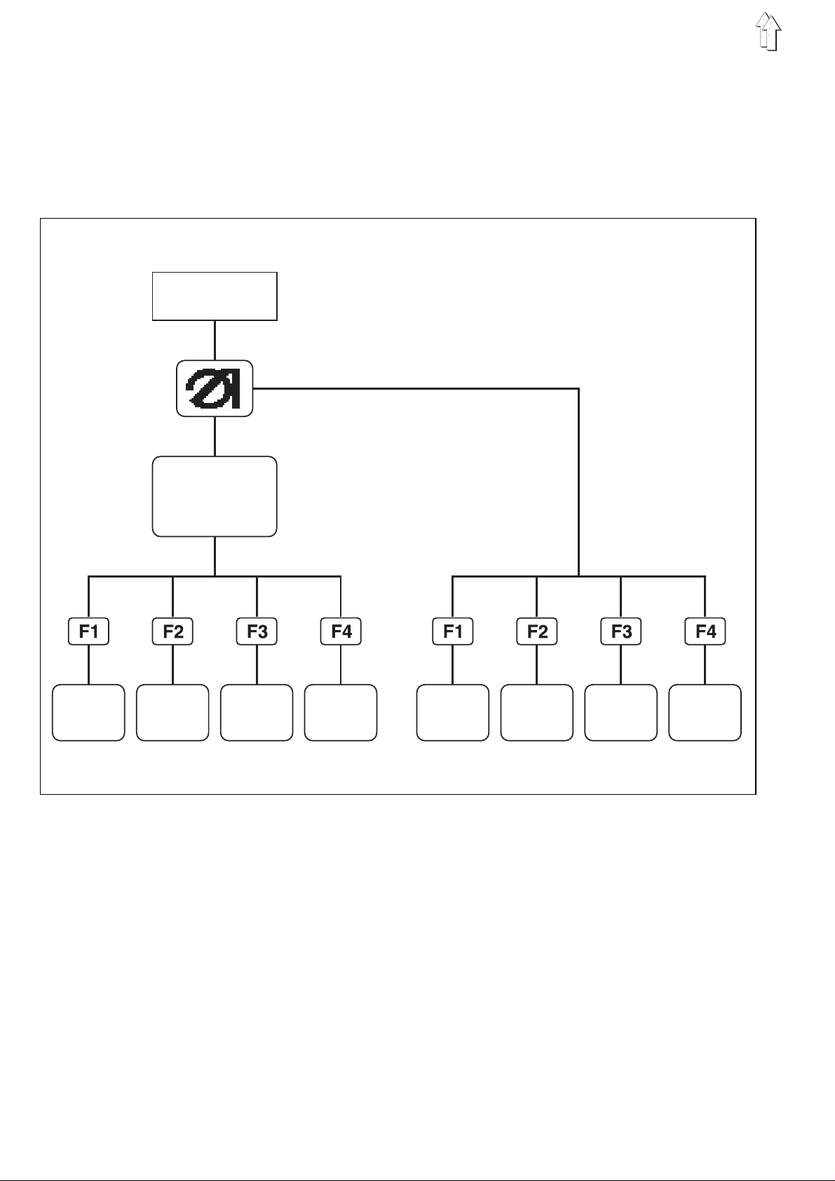
4. Operator Interface
4.1 Menu Structure of the Sewing and Testi ng Programs
In the design of the operator interface only internationally understood
symbols are used.
The individu al p ar a me te r s and setting and tes t i ng pr o gra ms a r e combined in different groups.
Turn on the
main switch
Main screen
Parameter me nu s of th e s e wi n g p rog r am s Setting and te s ting programs
Calling up sewing programs
–
Turn the main switch on.
The controls are initialized.
The DÜRKOPP-ADLER logo appears in the display for a short period.
–
The display c h an ge s to th e m ai n s c ree n.
By pressing one of the function keys F1 to F4 the correspon di n g
parameter menu of th e s e wi n g p rog r ams i s c al le d u p.
Calling up setting and testing programs
–
Turn the main switch on.
The controls are initialized.
The DÜRKOPP-ADLER logo appears in the display for a short period.
–
During the display of the logo
to F4.
The display changes to the corresponding group of the setting or
testing programs.
6
press one of the function keys
F1
4.2 Changing Parameter V alues
The parameter values can be changed in the different parameter screens.
–
–
–
–
Select the desired parameter with the cursor keys "" or "" .
The symbol of the selected parameter appears inversely.
Press the enter key.
The parameter sc r e en ap pe ars with the prompt an d w i th th e c u r rent setting of th e p ar a me te r v alu e.
Enter parameter value as described in 1. to
Press the enter key.
The new setting of th e p ar a me te r v alu e i s st or e d.
4.
(on) (off)
20
Enter: 08, 12, 14, 16, 20
-35
Enter: -99 ... +99
When changin g t he parameter value s i t m us t be di ffer e nt i at ed be tw ee n
four groups o f p ara meters.
1. Functions , which a re turned on/off
–
Turn the function of the parameter on or off with the cursor keys
"" or "".
2. Parameters with different functions
–
Set the desi red fu nc t ion of the parameter wit h t he cur so r key s ""
or "".
3. Parameters, whose values are changed in steps
–
Select the p r ev ious or next step of the parameter val u e with the
cursor keys "" or "".
4. Parameters, whose values are entered via the nume ric keys
–
Enter the desired parameter value with the numeric keys.
Attention!
The value must lie within the fixed limits.
Should a too lar g e o r to o s m all a v al u e h av e be en en te r ed , t he n
the upper or lower limit is display after the enter key is pressed.
–
If a sign ap pe ars i n fro nt of the parameter v alue, this can be c ha nged with the " " ke y.
7

5. Sewing Programs
With the
745-26/28
99 different sewing programs can be combined
with up to 25 se am pa tt ern s .
The individu al s e wi n g p r og ram s ( po ck et pr o gr a ms) c a n b e f r ee ly pr o grammed hereby.
For the sewi ng of po c k et sequences 4 indepe nd en t s e qu en c es are
available. E ac h i nd iv i du al s e qu en c e ca n be put together in an y de s i red
order out of a maximum of 6 pocket programs.
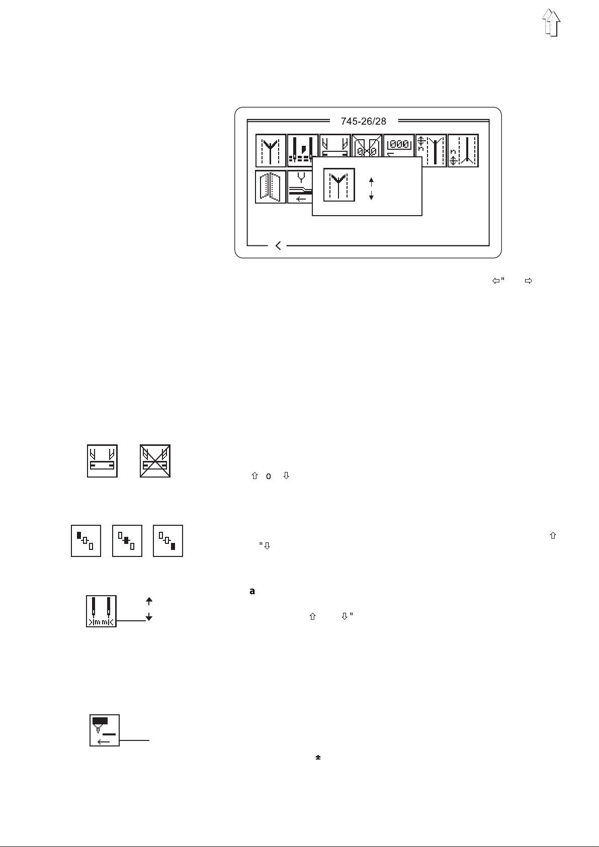
5.1 Calling Up Sewing Program Parameter Screens
From the main sc r ee n i t i s po s s i bl e to change to the different parameter screens o f t he s ew i ng pr o gr a ms with the functio n k e y s F1 to F4.
745-26/28
Σ
01
: 0100
03
02
1
4
2
5
3
6
SAKKO
GP
PP
PS
1.
2.
3.
4.
01
02
03
04
020304
745-26/28
05
06
SP
745-26/28
01
000
Global para me te rs Pocket prog ram Pocket sequ en c e Seam patterns
GP PP PS SP
Parameter screens of the sewing programs
Global parameters (GP): Parameters, which are valid for all
pocket progra ms
Pocket program (PP): Parameters for programming the seam
run and the ass o c i at ed s up pli m en tary
functions
Pocket sequence (PS): Programming of pocket sequences
Seam patterns (SP): Parameters for programming the seam
patterns
8

5.2 Starting the M achine P rogram
–
–
<==== REF
–
–
–
Turn the main switch on.
The controls are initialized.
The DÜRKO P P- A DL E R l o go ap pe ar s in the display fo r a s h ort period.
If, during the display of the logo, one of the function keys
F1
to F4 is pressed, the display switches over to the corresponding
group of the se tt i ng or t es t i ng programs.
The controls c h ec k i f the transport car ri ag e i s in its rear end pos i ti -
on.
If this is not the case the display shows "
<==== REF
" (reference
run).
Start the reference run by stepping back on the left pedal.
The display changes over to the main screen of the sewing unit.
From the main screen it is possible to change to the various parameter screens o f t he s ewing programs by pre s s i ng th e f un c ti o n
keys F1 to F4.
The machine program is exited by pressing the "
STOP
" key.
The controls are initialized.
9
5.3 Main Screen
On the main screen are displayed all important parameters, the seam
pattern and t he sel e c te d p oc k e t s e qu en c e.
01
01
01
01
01
01
03
03
03
03
03
03
02
02
02
02
02
02
745-26/28
SAKKO
01
Σ
: 0100
GP
03
02
L : 140
1
4
2
5
PP
3
6
PS
SP
Selecting a pocket sequence
In the upper left corner of the display the selected pocket sequence is
shown.
If the automatic change of pocket programs is active, arrows are
shown betwee n t he i nd i v i du al p ock e t p r og r am s of the sequence.
–
Change the pock e t se qu en c e w i th th e cu r s or k e ys "" or "".
"" key: Select the previous pocket sequence
"" key: Select the next pocket sequence
01
01
01
01
01
01
03
03
03
03
03
03
: 0100
Σ
L : 140
02
02
02
02
02
02
Selecting a pocket program in the current pocket sequence
In the pocket s e qu en c e a ba r ma rk s th e s e l ect ed pocket program.
A double bar indicates that in that pocket program the stacker is switched on.
–
Select a pocket program with the cursor keys "" or ""
"" key: Select the previous pocket program of the pocket sequence
"" key: Select the next pocket program of the pocket sequence
Piece counter
To the left under the pocket sequence the current piece count is shown
(e.g. "Σ : 0100").
The piece counter shows the number of pieces finished since the last
resetting of th e c o un te r.
The setting o f t he pi e c e c o un te r occ u r s under the "Global P ar a me te rs "
(function key F1).
Seam length
When sewing with distance measurement (without light barrier) the set
seam length appears at the right under the pocket sequence (e.g. "L :
140").
10
SAKKO
1
4
2
5
3
6
Seam pattern
In the right half of the display the seam pattern of the selected pocket
program is sh ow n.
Above the seam pattern the corresponding program name appears.
ATTENTION !
In order to as sociate the pock et pro gr a m w i th a s p ec i f i c
seam pattern , c h an ge to the parameter scr ee n o f t he
pocket programs (PP) with the function key F2.
There the des ir e d s e am
pattern can be accessed with the " " symbol.
The association of a seam pattern
not
is
possible via the main screen!
Altering parameters
The six parameters in the lower left half of the display make possible a
quick access to the six most important parameters of the current
pocket progra m.
They can be altered directly with the numeric keys.
The number of the key to be pressed is shown at the right next to the
parameter symbol.
1: Switching the corner knife on/off
2: Correcting the seam beginning with the light barrier
( seam length )
3: Correcting the seam end with the light barrier
( seam length )
4: Switching the piping knife on/off
5: Correcting the corner knife incision at the seam beginning
6: Correcting the corner knife incision at the seam end
The function s an d s e tt i ng s of the individua l pa ram et er s a re d es c ri b ed
in more detail i n t he Ch ap te rs 5. 4 (" Gl o ba l P ara me te rs " ) an d 5 .5
("Pocket Program").
The function c orr e c ti n g t he s ea m b eg i nn i ng or c o r rec t i ng th e s e am en d
with the light barrier ( seam length ) can be changed to
measurement
Description see chapter 5.3.2.
Selecting t he fu nc t i on oc c u rs un de r th e " P o ck et P r og ram " .
( Number 2 ).
distance
11

Correction the seam beginning with the light barrier
With the chan ge of the value the co rne r k ni f e i s d r aw n o nward accordingly at the seam beginning.
Enter: -99...+99 0 = No correction
+ = Seam beginning earlier
- = Seam beginning later
Step size: 0.1 mm
Correction the seam end with the light barrier
With the chan ge of the value the co rne r k ni f e i s d r aw n o nward accordingly at the seam end.
Enter: -99...+99 0 = No correction
- = Seam end earlier
+ = Seam end later
Step size: 0.1 mm
Correction of the corner knife on the seam beginning
With the chan ge of the value a fine ad j us t me nt of th e c o r ne r k ni f e i n c i sion at the se am be gi n ni n g o c c urs .
Enter: -99...+99 0 = No correction
+
-
+ = Corner incision earlier
- = Corner incision later
Step size: 0.1 mm
Correction of the corner knife on the seam end
With the chan ge of the value a fine ad j us t me nt of th e c o r ne r k ni f e i n c i sion at the se am en d o c c urs .
Enter: -99...+99 0 = No correction
- = Corner incision earlier
+
Selecting parameter screens
By pressing th e a pp r op r iate function key F1 to F4 the display changes
to one of the fo ur p ara meter screens.
F1
: GP (Global parameter)
F2
: PP (Pocket program)
F3
: PS (Pocket sequence)
F4
: SP (Seam patterns)
By pressing the function key
ens to the main s c reen.
F1
one returns from the parameter scre-
+ = Corner incision later
Step size: 0.1 mm
5.3.1 Automatic recognition of the flap angle
When the unit is supplied with the kit 0794 002472 , Automatic Detection of Inclination, (auxiliary equipment), the 2nd LED must be activated.
The flap to be sewn, shown on the main screen, will appear dashed.
12

5.3.2 Sewing distance measurement
For measuring the seam length, two possibilities are available.Use the
pocket programme for selecting. The two possibilities are reciprocally
locked, i.e. that only one of the two possibilities can be selected. The
other one is d ea c ti va ted.
Automatic recognition of the flap beginning and end
With this setting the reflecting light barrier for the recognition of the
seam beginni ng an d s e am en d when sewing with fl a p i s s w i tc h ed on .
Distance measure me nt
The shortest seam lengths which can still be sewn with the distance
measurement are dependent on the following parameters:
- Maximum seam length (180 or 220 mm)
- Subclass (-26 or -28)
- Selected po s iti o ni n g p oi n t
Forward positioning point:
Rear positioning poi nt:
Central positioning point:
Needle Clea rance Shortest Seam Length
max. Seam Length Shortest Seam Length
[mm] [mm]
815
10 20
12 25
14 30
16 35
20 40
[ mm] [mm]
745-26 745 -28
180 20 60
220 60 100
Sewing Length Shortest Seam Length
[mm] [mm]
745-26 745 -28
180 20 20
220 60 90-APM
*
APM = Position of the central positioning point
*
The shortest seam length, however, may not fall short of that
given for the fo r wa r d p osi t i on i ng po i nt .
The change of the seam length parameter value is done on the main
screen.
–
Operate the k e y " 2 " .
The setting window, prompting to enter, will appear.
–
Change the parameter as described under chapter 4.2.
13

5.4 Global Parameters ( )
Global parame te rs are pa r am et ers , wh i ch a pp l y fo r
grams.
Example: If the co r ne r k ni f e i s switched off
made without corner knife incisions.
–
With the main s c ree n as shown press fu nc t i on k ey F1.
The display changes to the screen for the global parameters.
–
Select the desired parameter with the cursor keys "" or "".
The symbol of th e s e lec t ed parameter appears i nv e rs el y.
–
Change the sel ect ed pa r am et er a s de sc r ibe d i n Ch ap te r 4. 2.
–
By pressing the function key F1 the display returns to the main
screen.
all
all
pocket pro-
pockets will be
Switching the corner knife on/off
Enter: on/off
Switching the center knife on/off
Enter: on/off
ATTENTION !
When the center knife is switched off the
corner knives are also automatically switched off.
When the cen te r k ni f e i s switched on again ,
the corner knives remain switched off.
They must be switched on separately.
Switching the piping knife on/off
Enter: on/off
14
Setting the closing order of the flap clamps
6 different settings can be chosen:
Without flap clamps
Close first th e le ft , t he n t he ri gh t f l ap cl am p
Close first the right, then the left flap clamp
Close both flap clamps simultaniously
Only the right flap clamp exists
Only the left fl a p cl a mp ex is t s
Piece counter
The piece counter shows the number of pieces completed since the
last resetting of the counter.
Enter: 0...9999
Correcting the center knife incision at the seam beginning
With a change of the value a fine ad j us t me nt of th e c e nt er k n if e inc i s i on at the seam be gi n ni n g o cc ur s.
Enter: -15...+15 0 = No correction
+ = Turn the center knife on earlier
- = Turn the center knife on later
Step size: 1 cycle = 0.4 mm
ATTENTION !
An Offset can be en te red fo r th e p ock e t p ara me te r s.
Correcting the center knife incision at the seam end
With a change of the value a fine ad j us t me nt of th e c e nt er k n if e inc i s i on at the seam en d o c cur s .
Enter: -15...+15 0 = No correction
+ = Turn the center knife off earlier
- = Turn the center knife off later
Step size: 1 cycle = 0.4 mm
ATTENTION !
An Offset can be en te red fo r th e p ock e t p ara me te r s.
Activate working method for breast welt pocket (745-28 A)
The breast welt pocket working method will be connected / disconnected.
Enter: on/off
15

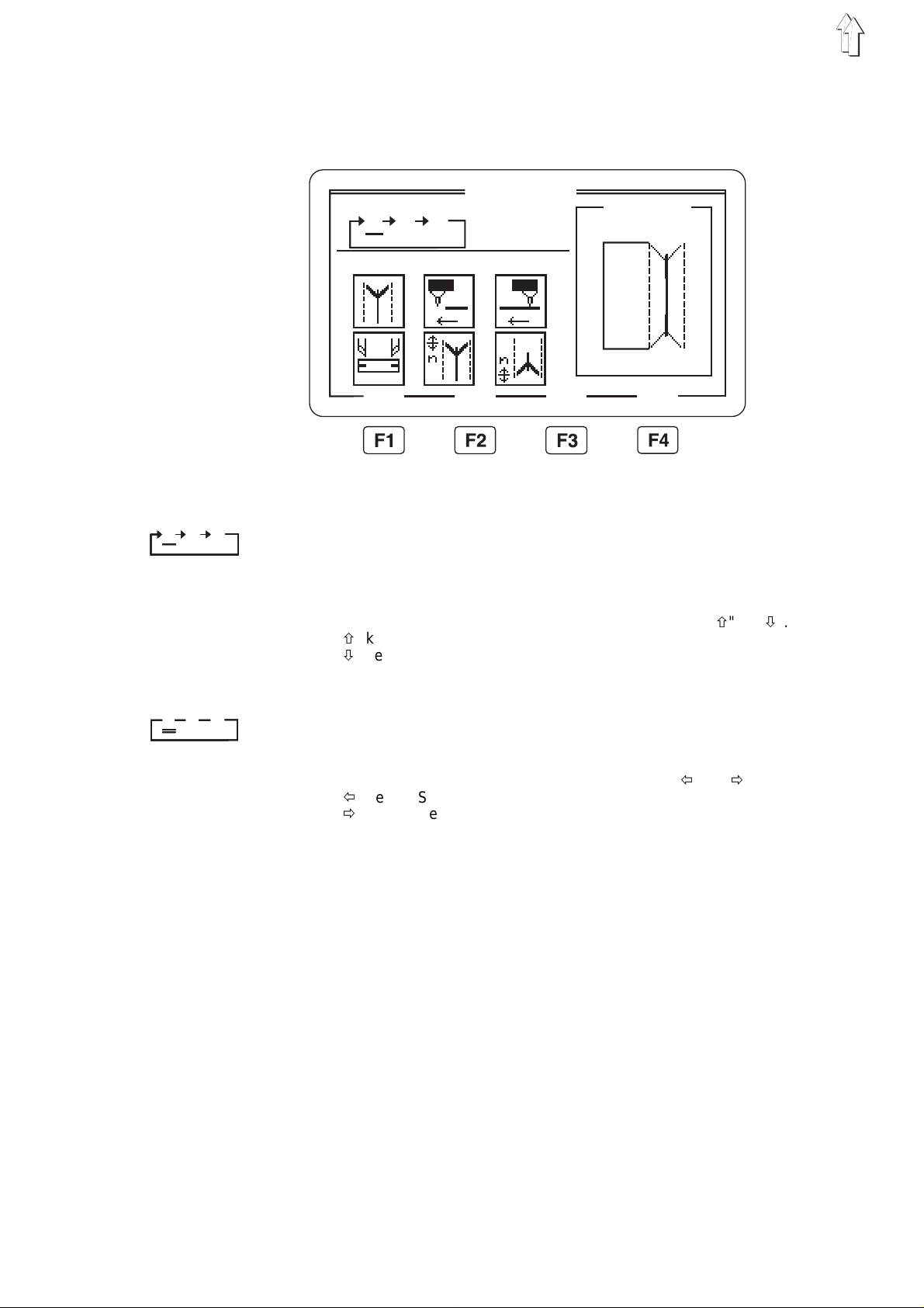
5.5 Pocket Program ( )
Under this menu i te m a re l o c at ed th e p ara me te rs fo r pro gra mm i ng th e
various pocket programs.
With the aid of the parameters the seam run and the supplimentary functions assoc i a te d with it are freel y pr o gra mm ed .
16
–
With the main s c ree n as shown press fu nc t i on k ey F2.
The display changes to the pocket program screen.
By pressing the function key F4 the display changes to the second
screen of the pocket program.
–
In the upper left line of the display is shown the currently selected
").
PP : 01
").
SP : 01
").
pocket program (e.g. "
If it exist s , t he as s o ci at ed program name app rea r s be l ow i t
<JACKET>
(e.g. "
–
In the upper right corner of the display the seam pattern number of
the selected pocket program appears (e.g. "
–
Select the desired parameter with the cursor keys "" or "".
The symbol of th e s e lec t ed parameter appears i nv e rs el y.
–
Change the sel ect ed pa r am et er a s de sc r ibe d i n Ch ap te r 4. 2.
–
By pressing the function key F1 the display returns to the first
screen of the pocket program or to the main screen.

Pocket program number
With this pa r am et er the pocket progra m t o b e c h an ge d i s s e l ected.
After compl et i on of th e e ntry the new pocket program and the corre-
sponding program name appear in the upper left corner of the display.
Enter: 1...99
Sewing distance measurement
Two different possibilities can be selected. Use the pocket programme
for selecting. The two possibilities are reciprocally locked, i.e. that only
one of the two possibilities can be selected. The other one is deactivated.
Distance measure me nt
When useing distance measurement, the seam length is entered with
the main scr ee n b ei n g o n.
Automatic recognition of the flap beginning and end
With this setting the reflecting light barrier for the recognition of the
seam beginni ng an d s e am en d when sewing with fl a p i s s w i tc h ed on .
Automatic recognition of the flap angle
When the unit is supplied with the kit 0794 002472 , Automatic Detection of Inclination, (auxiliary equipment), the 2nd LED must be activated.
The flap to be sewn, shown on the main screen, will appear dashed.
Selecting the positioning point
Depending on th e t y pe of go od s to be s ew n, po s i ti o ni n g o c cur s a t t he
rear, central or forward positioning point.
Rear positi o ni n g p oi n t (toward the operat or )
Central positioning point
Forward positioning point (to the machine head)
All positioning lights on/off
Enter: on/off
on = all positioning lights are switched on
off = positioning lights are switched as set in the
pocket programm
17

Stitch condensation or bartacking at the seam beginning and
seam end
By changing this parameter a coice is made whether the seam beginning
and seam end are executed with stitch condensation or with bartacking.
with stitch condensation
with bartacking
ATTENTION !
By 1.4 mm stitch length in stitch condensation the
bartacking is sewn with a stitch length of 0.8 mm.
Flap feed on/off
Enter: on /o ff (only bei fe ed me th od s B , C , F )
Sewing patterned or plain goods
Patterned goods (only with feed methods D, F)
Plain goods
Transport carriage return after sewing
Wait position
After the sewing the transpo rt c l a mp s au to ma ti c a ll y r un
back into the wait position without sewing goods.
Feed position
After the sewing the transpo rt c l a mp s au to ma ti c a ll y r un
back into the feed position without sewing goods.
Returm with sewing goods
(only with feed method A)
After the sewing the transport clamps transport the
sewing good s ba c k i nt o t he fe ed ar e a.
Stacker on/off
Enter: on/off
18

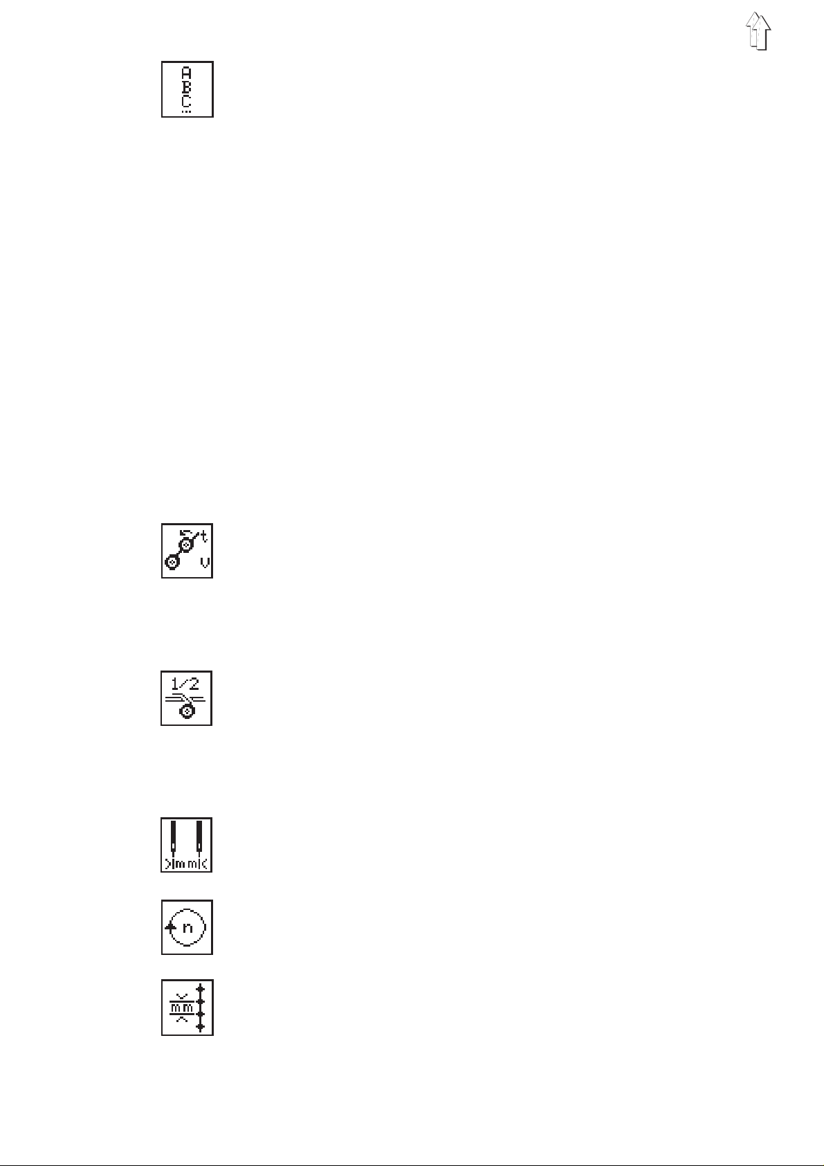
Smoother on/off
Enter: Active period: t = 5...20
Step size: 1 cycle = 0.1 s
Speed level: v = 5...15
Note:
With the smoo th er t he r e i s a du al u s e o f t he solenoid valv es :
–
Stacker switched on: The smoother is triggered as a stacker
supplement (Y63).
–
Stacker sw itched off: The smoother is t ri gg er e d a s an ejector (Y42) .
ATTENTION !
If both a stacker and a smoother are available and
no stackin g p roc e du r e t ak e s place, then both
parameters mu st b e switched off!
Tape feed on/off
Enter: Tape length at the seam beginning:20...100 [mm]
Tape length at the seam end: 20...100 [mm]
Hold-down on/off
Enter: on/off
Vacuum on/off
Enter: on/off
Setting the feed speed
The feed speed, between the loading station and the needle, can be reduced in step s of ea c h 1 0%.
Enter: 50...100 (100%)
Associating a seam pattern to the pocket program
After this parameter is selected the display changes to the seam pattern screen.
There the selected seam pattern can be changed or a different seam
pattern selected (see Chapter 5.1).
After the ret ur n to th e m ai n s cr ee n ( f un c ti o n ke y F1) the last seam pattern created is associated to the current pocket program.
ATTENTION !
The association of a specific seam pattern with a
pocket program must be made with the " " symbol.
This association is
screen (SP/F4)!
not
possible vi a t he main
19

Copying a pocket program
With this parameter the selected pocket program can be copied into
another pock et .
The number to b e e nt er e d s h ow s th e p oc k e t p rog r am i nt o w hi c h th e s e lected pock et pr o gra m i s t o b e c o pi e d.
After compl et i on of th e e ntry the number and n ame of the pocket pr o gram into whic h t he c opy wa s ma de ap pe ars i n th e u pper l e ft cor n er o f
the display.
Enter: 1. .. 99
Entering program names
This paramete r en ab l es t he l ab el i n g o f e ac h po c ket pr o gr a m w i th an i ndividual program name (e.g. "JACKET").
The program name may have a maximum of 8 letters.
–
Press the "" or "" cursor key.
A window is opened in the lower right corner of the display.
The program name of the current p ock e t p r og ram appears in this
window.
If the curre nt po c k et pro gr a m w as n ot y et gi v e n a pr o gra m n ame
the window remains empty.
–
One moves through the alphabet with the function keys F2 and F3.
F2
: move forward
F3
: move back
–
By pressing the cursor keys "" or "" the cursor moves one position to the l e ft or r i g ht r esp ec t i v el y.
–
Press the enter key.
The entry is completed.
The entered p r og ram na me is stored.
By pressing the "
ESC
" key the ol d p rogram name is used a ga i n.
Selecting pedal mode
When using the loading mode with vacuum and/or holding-down
clamp, it is p os si b l e t o s e l ec t be tw ee n t w o v ari a nt s .
For selecting th i s mo de wi t h t he po c ket pr o gra mm e, th e
Vacuum and/or the Down-holde r c l am p m ust be ac t i ve.
When loading , the pedal must fi r st be treaded into i ts b asi c
position. T he n i t mu s t b e o pe r at ed on c e ag ai n , be fo re the
feeding clam p t r av e l s to th e s e am be gi n ni n g.
When using th i s mo de , o nl y o ne pe da l op eration is requir ed
for starting the loading process.
20

5.6 Pocket Sequence ( )
Under this menu item the individual pocket programs are combined
into sequences which can be called up.
A total of 10 independ en t p ock e t s e qu en c es a re a v ai l a bl e .
Each pocket sequence can be combined out of up to six pocket programs in any de si r ed ord er.
745-26/28
02
03
04
05
06
01
1.
02
2.
03
3.
04
4.
Programming a pocket sequence
–
With the ma i n sc r e en as s h own press the function key F3.
The display changes to the pocket sequence screen.
The display shows the four current pocket sequences.
–
Move the cursor with the cursor keys "" or "" to the desired
pocket sequence.
The number of the selected pocket sequence appears inversely.
–
Program the pocket sequence.
Enter the numbers (01...99) of th e d es i red pocket program s c on secutively with the numeric keys.
With singl e d i git pocket program n um be r s a " 0 " must be entered in
front of the desired number.
After the si x th po c ket program is enter e d t he pr o gra mmed pocket
sequence is automatically saved.
–
Press the enter key.
The pocket sequence is saved.
By pressing th e "
quence is re sto r ed .
–
By pressing the function key F1 the display is ret urned to th e m ain
screen.
ESC
" key during programming the old pocket se-
Automatic change of the pocket programs on/off
If this function is switched on the controls automatically move to the
next pocket p r og ram of the pocket sequ en c e a ft er a pocket program
has been worked th r ou gh.
–
Turn the automatic c h an ge of the pocket prog ram s on or o ff by
pressing the function key F4.
The automatic change is shown in the display by arrows between
the individual pocket programs of the pocket sequences.
21

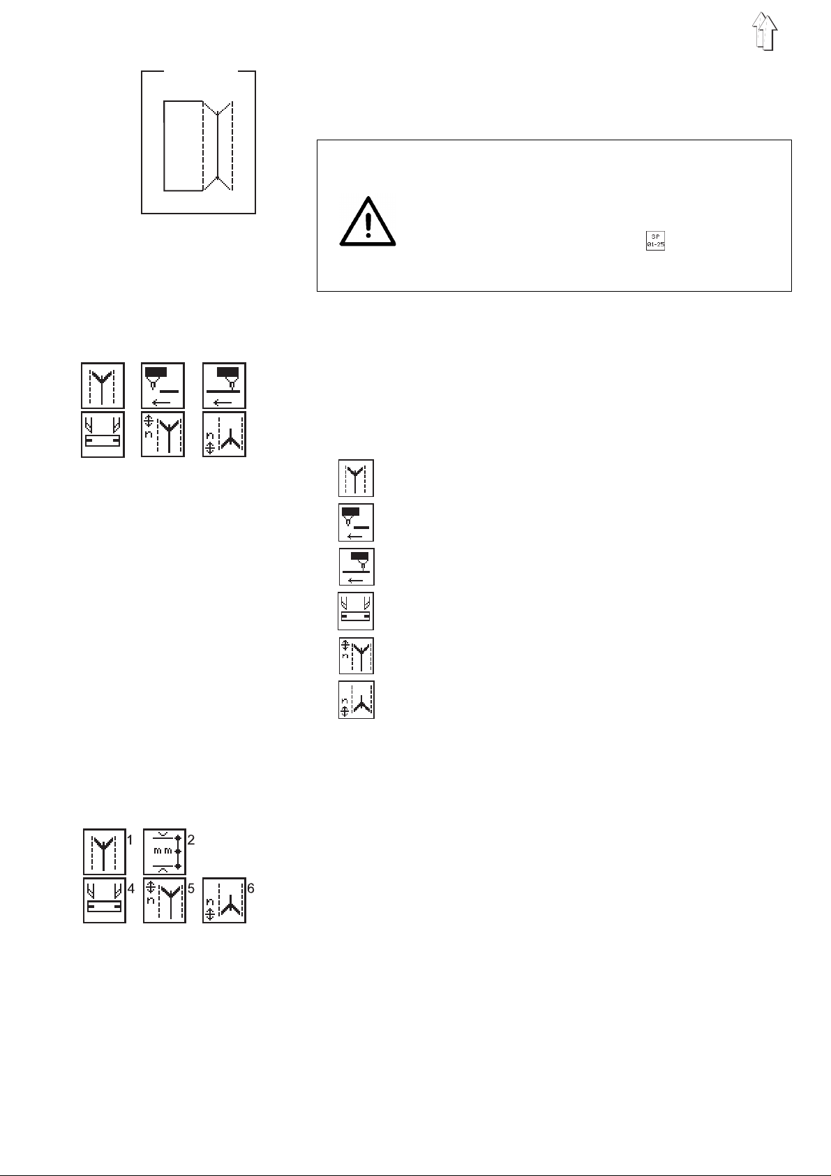
5.7 Seam Patterns ( )
Under this menu i te m u p t o 2 5 d iffer en t se am pa tterns can be progra mmed.
745-26/28
01
000
–
With the main screen as shown press the function key F4.
The display changes to the seam pattern screen.
–
Three parameters for the programming of the seam pattern number, the flap side and an ad di t i on al seam offset appear in th e l e ft
third of the d i s pl a y.
In the windows in the center of the display are shown the flap form
(left window ) a nd th e s e am pa tt ern ( ri gh t w i nd ow ).
In the window in the right third of the display is shown the
complete seam pa tt er n wi t h f lap .
–
Select the desired parameter with the cursor keys "" or "".
The symbol of th e s e lec t ed parameter appears i nv e rs el y.
–
Change the sel ect ed pa r am et er a s de sc r ibe d i n Ch ap te r 4. 2.
–
By pressing the function key F1 the display returns to the main
screen.
Selecting a seam pattern
After the initialization of the program memory 25 standard seam patterns are filed in the cont rols (see Appendix A1).
They can be called up directly by entering the seam pattern number.
Enter: 1...25
Selecting a flap side
The sewing unit is equipped with a reflected light barrier for the recognition of the seam beginning and seam end when sewing with flap.
The parameter shows the side on which the flap is positioned.
With the a change of the parameter the flap side of the seam pattern in
the right third of the display automatically changes.
flap at the left
flap at the right
22

Additional seam offset
Enter: 0...20 [mm]
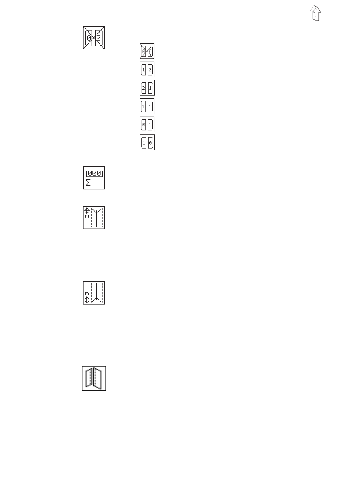
Selecting the flap form at the seam beginning
With the cursor keys "" or "" a choice can be made between the following seve n f l ap fo r ms :
The numbers above the flap forms denote the different angles.
Selecting the flap form at the seam end
With the cursor keys "" or "" a coice can be made between t he fo l l owing seven flap forms:
The numbers under the flap forms denote the different angles.
Selecting the seam pattern at the seam beginning
With the cursor keys "" or "" a choice can be made between the following seve n s e am pa tt er n s :
The numbers over the seam patterns denote the different angles.
Selecting the seam pattern at the seam end
With the cursor keys "" or "" a choice can be made between the following seve n s e am pa tt er n s :
The numbers under the seam patterns denote the different angles.
23

6. Setting and T esting Programs
The machine s o ft wa re encompasses differ e nt ma c hi n e-s p ec i f i c s et ti n g
and testing programs and the well-known Multitest system.
A terminal selftest checks the individual components of the operator
terminal.
6.1 Calling Up Setting and Testing Pr ograms
After the sewing unit is turn ed on one can change ov e r to the different
groups of setting and testing programs with the function keys F1 to F4.
Turn the
main switch on
Dürkopp Adler AG
745-26/28
05.05.95
Selftest
F
RAM
EPROM
RAM-Card
Keyboard
F
F
Interface
Display
List
Exit
Machine Parameters Machine-specific Multitest System Terminal Selftest
Setting and Testing (only for service staff)
Programs
24
–
Turn the main switch on.
The controls are initialized.
The DÜRKO P P- A DL E R l o go ap pe ar s in the display fo r a s h ort period.
–
While the lo go i s vi s i bl e pre s s on e o f t he fu nc t i on k ey s F1 to F4.
The display changes to the corresponding group of setting and testing programs.

6.2 Machine Parameters ( + )
STOP
The machine p arameters describe the technical exe c ut i on of the sewing unit, as well as the machine settings and their correction values.
ATTENTION !
As a rule changes in the machine settings result in mechanical conversions.
For this reas o n t hi s part of the program c an on l y be ac cessed after entering the co de nu mb er "
25483
".
Code
–
While the DÜRKOPP-ADLER logo is visible press the function key
.
F1
The prompt for the code number appears in the display.
–
Enter the co de nu mb er "
–
After the entering of the corr e c t code number the dis p l ay c h an ge s
to the machine parameter screen.
With an incorrectly entered code number the display changes to
the main scr ee n.
–
Select the desired parameter with the cursor keys "" or "".
The symbol for the selected parameter appears inversely.
–
Change the selected parameter as described in Chapter 4.2.
–
To exit the machine parameters press the "
Selecting the subclass
Enter: 26, 28
Maximum sewing di st a nce
Enter: 180, 220 [mm]
" with the numeric keypad.
25483
STOP
" key.
25
Feed device
Enter: A, B, C, D, F, H
745-26 745-28
X
XXB: Pip ed pockets,
XXC: Pip ed pockets,
: Pip ed pockets,
A
manual positioning of the piping strip,
flap and oth er s u pp l i me nt ar y p art s
automatic fe ed of th e p i pi n g s t ri p,
without cutting of the piping ends
automatic fe ed of th e p i pi n g s t ri p,
with cutti n g o f t he pi p i ng en ds
X
X
XXH: Sewi n g i n of th e s e win g u ni t
Activating the smoother
This paramete r s i gn als t he c on tr o l s if the sewing unit i s e qu i pp ed wi t h
a smoother.
The smoother is turned on and off in the main screen under the menu
item "Pocket Program" (F2).
Enter: on/off
Switching the tape feed on/off
This paramete r s i gn als t he c on tr o l s if the sewing unit i s e qu i pp ed wi t h
a tape feed.
The tape feed is turned on and off in the main screen under the menu
item "Pocket Program" (F2).
Enter: on/off
: Bre as t po c k et s,
D
automatic fe ed an d a l i gn ing of
the breast selvage
: Piped pockets,
F
automatic fe ed of th e p i pi n g s t ri p,
automatic fe ed an d a l i gn ing of the flap,
with cutti n g o f t he pi p i ng en ds
(only for service staff)
26
Needle clearance
Enter: 8, 10 , 1 2, 14 , 1 6, 20 [mm]
Sewing rpm
Enter: 25 00 , 2 75 0, 30 00 [r p m]
Stitch length
Enter: 2.55, 3.10 [mm]

Stitch length in the stitch condensation
Enter: 0.50, 0.80, 1.40 [mm]
Number of stitches in the stitch condensation
Enter: 5...10 [stitches]
Switching the thread monitors on/off
With this pa r am et er the needle thread
switched on and off.
Enter: on/off
Displays: Needle thread breakage:
Underthread bobbin empty:
Clearance of the rear positioning point to the central positioning
point
Enter: 40...120 [mm]
underthread monitors are
and
The empty bobbin blinks.
Switching the remover on/off
This paramete r s i gn als t he c on tr o l s if the sewing unit i s e qu i pp ed wi t h
a remover.
The remover is turned on and off in the main screen under the menu
item "Pocket Program" (F2).
Enter: on/off
Switching the stacker on/off
This paramete r s i gn als t he c on tr o l s if the sewing unit i s e qu i pp ed wi t h
a stacker.
The stacker i s t urn ed on and off in the main s c ree n u nder the menu
item "Pocket Program" (F2).
Enter: on/off
27

6.3 Machine-specific Setting and Testing Programs ( + )
The machine-s p ec i f i c testing programs s erv e fo r th e setting and testing of the individual machine components.
–
While the DÜRKOPP-ADLER logo is visible in the display press
the function key F2.
The display changes to the machine-specific testing programs screen.
–
Select the desired testing program with the cursor keys "" or "".
The symbol fo r th e s e l ec t ed te s ti n g p rog r am ap pe ar s in v er sely.
–
Start the selected testing program with the enter key.
Attention!
play did not c ha ng e, on l y th e s m oo th er w or ks .
After starting the pro gram "Testing smoother" the dis-
STOP
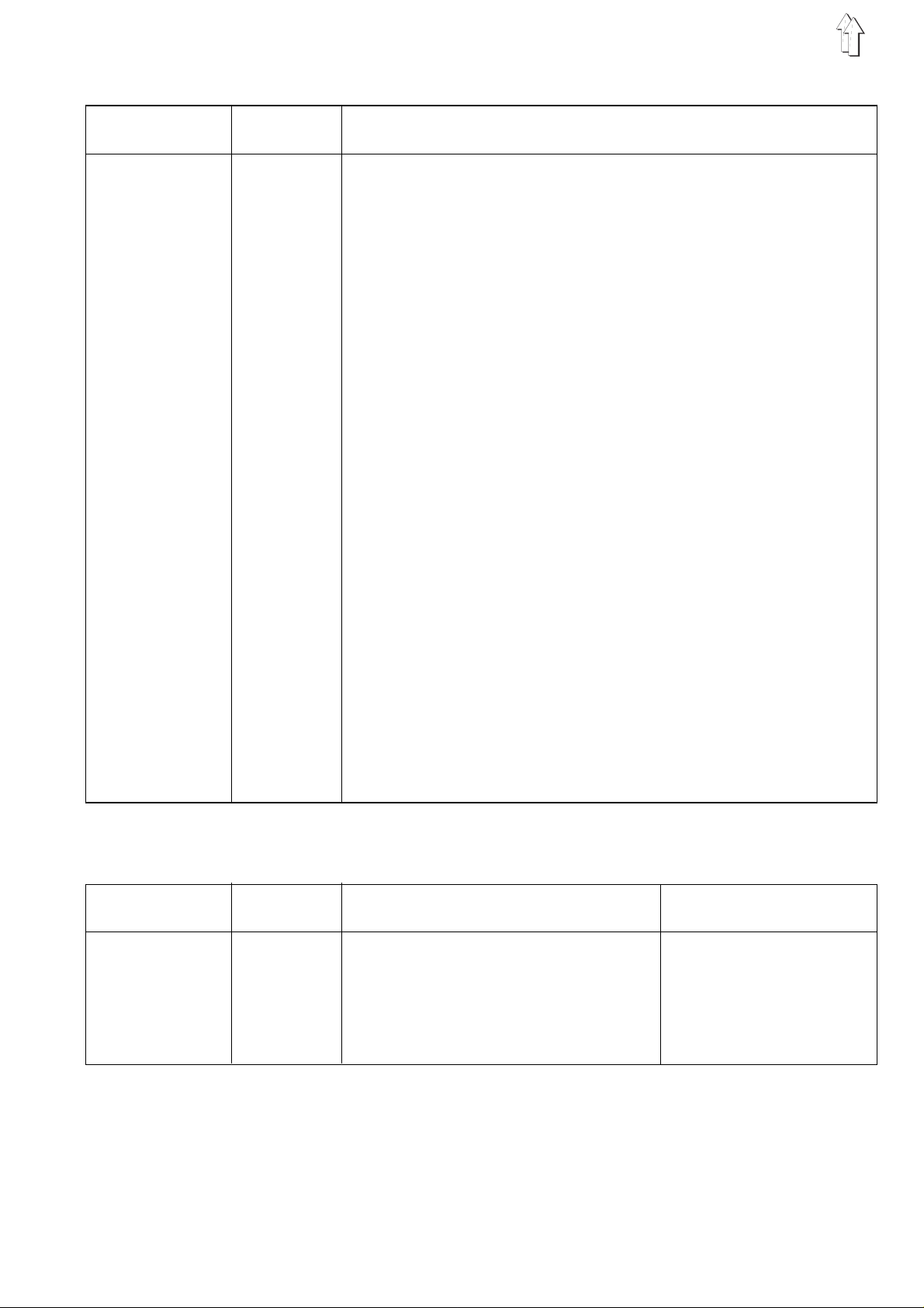
6.3.1 Setting the Underthread Monitor
This program s erv e s fo r th e alignment of the r e fl e c te d l ig ht barriers of
the underthread monitor.
–
Start the testing program with the enter key.
The displa y s ho ws t w o un de rt h rea d b ob bi n s an d t he r ef l ec t i ng
heads of the light barriers.
–
With a correct alignment of the light barriers a reflection occurs
when an empty bobbin is turned.
A reflection is sho wn by a n a r row between the reflec t i ng he ad an d
the underth rea d b ob bi n .
At the same time a signal tone can be heard.
–
To exit the testing program press the function key F1.
745-26/28
28

6.3.2 Initializing the Program Memory
The program se r ves t o l o ad a s t an da r di z e d f ac t ory s e tt i ng fo r th e p arameters of the se wi n g p rog r am s.
ATTENTION !
After start i ng on e o f t he fo ur p r og ram s a s t an da r diz e d f ac t or y se tting
will overwrite the set parameters!
For this reas o n t he pr o gra m c a n o nl y b e s t art ed after entering th e co de
number "
25483
745-26/28
".
Code
–
Start the t est i ng pr o gr a m w i th th e e nt er k e y.
The display s h ow s th e p r om pt fo r th e c o de nu mb er.
–
Enter the co de nu mb er "
–
After the entering of the corr e c t code number the dis p l ay c h an ge s
to the five parame te rs de s cr ibe d b elo w.
After the entering of an incorrect code number the display returns
to the machine-specific parameter screen.
Initialization of defective machine parameters
Initialization of defective pocket programs
Initialization of defective pocket sequences
Initialization of defective seam patterns
Initialization of
–
Select the desired program with the cursor keys "" or "".
The symbol for the selected program appears inversely.
–
Start the se l ec t ed pr o gra m with the enter ke y.
–
To ex i t th e t es t i ng pro gr a m p r ess t he function key F1.
" with the numeric keypad.
25483
programs and parameters
all
29

6.3.3 Checking the Smoother Function
With this program the smoother function is tested.
–
Start the testing program with the enter key.
The symbol ap pe ars i n th e lo we r ri gh t c o rne r of th e d is pl a y wi t h a
prompt.
–
Enter the desired values for "t" and "v".
Enter: Active period: t = 5...20
745-26/28
20
15
Step size:1 cycle = 0.1 s
Speed level: v = 5...15
–
–
6.3.4 Aligning the Light Barriers
The program serves for the alignment of the reflected light barrier for
the recognition of the seam beginning and seam end.
After confirmation of the value for "v" the smoother runs for the selected acti v e pe ri od at the selected spe ed .
To exit the testing program press the function key F1.
745-26/28
30
–
Start the testing program with the enter key.
Two light barrier symbols appear in the center of the display.
–
Manually pus h th e t r an s po rt c l a mp un de r th e re fl e c te d l i g ht ba r ri er.
With a refl ec t i on an ac o ustic signal is h ea rd.
The displa y of the light barri er sy m bo l s c ha ng es from inverse to
normal.
–
To exit the testing program press the function key F1.

6.3.5 Setting the Corner Knife Adjustment
With this program the corner knife clearance and the angle of the corner knife ca n b e set.
The minimum a nd ma x i mu m c o rne r k nife clearances are dependent on
the subclas s and the equipment of th e s e wi n g u ni t .
–
Start the t est i ng pr o gr a m w i th th e e nt er k e y.
–
Set the max imu m or minimum corne r k ni f e c l e ara nc e wi t h t he cursor keys "" or "".
–
Set the angl e of th e c o rne r k ni f e w i th th e f un c ti o n k e y s F3 (corner
knife seam be gi n ni n g) a nd F4 (corner kni f e seam end).
The seam beginning and seam end each have a choice of seven
angle settin gs a v ai l a ble.
745-26/28
Corner knife se am be gi n ni n g (F3):
Corner knife se am en d (F4):
Caution Risk of Injury !
Danger of cuts!
Do not reach int o t he ar e a o f t he ri si ng c orn er kn i v es.
–
Press the "" cursor key.
The corner knives rise.
–
Press the "" cursor key.
The corner kni ves l o we r ag ai n .
–
To ex i t th e t es t i ng pro gr a m p r ess t he function key F1.
31

6.3.6 Checking the Switching-in of the Needle and Center Knife
This program checks the switching-in of the needles and the center knife with the sewing drive running.
745-26/28
–
Start the testing program with the enter key.
–
Press function key F2.
1st operation: Start of the sewing drive at 1000 rpm
2nd operation: Running the sewing drive at 3000 U/min
3rd operation: Stop in position 2 (thread lever high position)
–
Turn the center kni fe on an d o ff wi th th e function key F3.
–
Turn the needles on and o ff wi th th e f un c tio n k e y F4.
–
To exit the testing program press the "
STOP
" key.
ATTENTION !
Before exiting the program it is essential to let the machine head run
briefly wi th th e n ee dl e s an d center knife turne d o ff.
Otherwise the next seam will not be executed correctly.
6.3.7 Checking the Tape Feed Function
This program te s ts t he tra ns p or t an d c u tt i ng fu nc t i on of th e t ap e feed.
745-26/28
ON OFF
32
–
Start the testing program with the enter key.
–
Press function key F2. The tape feed starts.
–
Press function key F3.
The motor of the tape feeds stops.
The tape is automatically cut.
–
To exit the testing program press the function key F1.

6.3.8 Checking the Catch-folder without T r ansport Clamp
This program te s ts t he fu nc t i on of th e ca tc h - fo lde r.
The transport c l am ps re ma i n i n th ei r re ar e nd po s i tio n hereby.
745-26/28
–
Start the t est i ng pr o gr a m w i th th e e nt er k e y.
–
Press function key F3.
The catch-fol d er s w i ng s into the vertical p os i t i on an d l o we r s on to
the material slide plate.
–
Press function key F2.
The catch-fol d er ri s e s an d s w i ng s ove r th e f ee d b oard.
–
To ex i t th e t es t i ng pro gr a m p r ess t he "
STOP
" key.
6.3.9 Checking the Feed Procedure with T ranspor t Clamp
This program s erv e s fo r te s ti n g t he feed procedure.
745-26/28
–
Start the t est i ng pr o gr a m w i th th e e nt er k e y.
A reference run is cond uc t ed .
–
Step on the p ed al .
The transport carriage runs to the feed station.
–
The feed proc e du re i s r u n t hro ugh as in a sewing pro gr a m.
After operat i on of th e l a s t s t ag e a n a r row appears in the d i spl a y.
–
Run the tran s po rt c a r ri ag e i n to th e r e ar p os i t i on by stepping on the
pedal in tap pin g operation.
In this position the transport carriage waits until the pedal is at rest.
–
The transport clamps rise and the flap clamps open.
–
The program i s r est ar t ed by s t ep pi n g o n t he pe da l .
–
To ex i t th e t es t i ng pro gr a m p r ess t he "
STOP
" key.
33

6.4 Multitest System ( + )
STOP
The testing programs of the Multitest system make possible the quick
checking of i np ut an d o ut pu t elements.
Additional measuring devices are not necessary.
–
While the DÜRKOPP-ADLER logo is visible in the display press
function key F3.
The display changes to the Multitest system screen.
–
Select the desired testing program with the cursor keys "" or "".
The symbol fo r th e s e l ec t ed te s ti n g p rog r am ap pe ar s in v er sely.
–
Start the selected testing program with the enter key.
6.4.1 Displaying the Program Version and Check Sum
The program checks the permanent store memory (ROM) of the
microcompu ter.
MULTITEST
EPROM-Test
ROM-Size
Class
Version
Date
Checksumme
Program vers io n
By program versions with the same class designation and the same
identification letter the higher version replaces all lower versions (Example: 745A03 replaces 745A01 and 745A02).
If a replacem en t i s p oss i b l e a l th ou gh th e i d en ti f i c at i on l et te r is di fferent this will be noted in a special communication to the customer.
: 192k EPROM
: 745-26/28
: 745A01
: 19.06.95
: 0x64AE
34
Check sum
The check sum is meant only for the factory service personnel.
It shows speci a l is ts if th e p r og ram me mo r y ( E PR OM ) of th e se wi n g
unit control s f l aw l ess l y contains the comp l et e p r og ram .
–
To exit the testing program press the function key F1.

6.4.2 Testing the Working Memory
The program checks the working memory (RAM) of the microcomputer.
–
MULTITEST
RAM-Test
RAM OK
Start the t est i ng pr o gr a m w i th th e e nt er k e y.
The display shows the test results.
Display Explanation
RAM OK
RAM-Error
–
To ex i t th e t es t i ng pro gr a m p r ess t he function key F1.
6.4.3 Displaying the Setting of the DIP Switches
The program sh ows the setting of th e DIP switches on th e CPU board
of the control u ni t.
MULTITEST
1
ON
OFF
Working memory functioning flawlessly
Error in the working memory
DIP-Switch
2345678
ATTENTION !
Currently the DI P swi tc h es a r e n ot em plo y ed on an y ma chi n e c la s s .
The setting of the various DIP switches has no influence on the operation of the sewin g u nit.
–
Start the t est i ng pr o gr a m w i th th e e nt er k e y.
–
To ex i t th e t es t i ng pro gr a m p r ess t he function key F1.
35

6.4.4 Selecting Input Elem ents
The program serves for the setting of the input elements.
MULTITEST
Input-Select
S ?
Input-Nr. :
ATTENTION !
All input elements were carefully set at the factory.
The setting and correction may only be conducted by trained service
personnel.
–
Start the testing program with the enter key.
–
Enter the code number of the desired input element with the numeric keypad.
The short de si gn ations of the circ u i t d i ag ram s er ve as c o de nu mbers (see following table).
–
The display s h ow s th e wiring diagram d es i g na ti o n a nd th e s w i tching status of the selected input element (e.g. "
+S17
").
The display changes when the switching status of the input element changes.
The switching status "+" means:
Contact swi tc h = Contact open
Proximity switch = Metal in front of the switch
Reflected light barrier = No reflection
Continuous beam barrier = Beam not interrupted
–
Set the input element until the display shows the desired switching
status.
–
To exit the testing program press the function key F1.
36
Input elements
745-26 745-28 Input Function
element A B C D F
XX
XX
XX
XX
XX
XX
XX
XX
XX
XX
XX
XX
XX
XX
XX
XX
XX
XX
XX
XX
XX
XX
XX
S01
S02
S03
S04
S05
S06
S07
S08
S09
S10
S11
S15
S17
S18
S23
S25
S26
S27
S28
S29
S30
S31
S32
Left pedal 1 X X X X X
Left pedal 2 X X X X X
Left pedal 3 X X X X X
Left pedal 4 X X X X X
Right pedal 1 XXXXX
Right pedal 2 XXXXX
Right pedal 3 XXXXX
Right pedal 4 XXXXX
Limit switch Knife bracket forward X X X X X
Limit switch Knife bracket back X X X X X
Knife bracket Reference point X X X X X
Limit switch Transport carriage forward X X X X X
Limit switch Transport carriage back X X X X X
Needle thread monitor left X X X X X
Needle thread monitor right X X X X X
Transport carriage Reference position X X X X X
Folder up X
Catch-folder up X X X
Positioning device up X
Folder down X
Catch-folder down X X X
Positioning device down X
Catch-fold er s w un g X X X
Positioning device swung X
Catch-folder vertical X X X
Positioning device vertical X
Flap seat up O
Pocket bag p l ac e me nt ti l t ed O
Pocket bag f ee d down O
Feed method
Light barrier inputs
745-26 745-28 Input Function Feed method
element A B C D F
XX
X
XX
XX
XX
X = S t an ar d eq ui p me nt
O = Optional equipment
S100
S101
S104
S106
S107
Flap scanning 1 XXXXX
Flap scanning 2 OOOOO
Stacking control X X X X X
Remaining thread monitor left X X X X X
Remaining thread monitor right X X X X X
37

6.4.5 Checking Input Elements
The program serves for the testing of the input elements.
MULTITEST
Input-Test
S26 :
–
Start the testing program with the enter key.
–
Operate the input element to be tested.
–
The display s h ow s th e wiring diagram d es i g na ti o n a nd th e s w i tching status of the selected input element (e.g. "
+S17
").
The display changes if the switching status is changed or some
other input element is changed. A change of the switching status is
shown by an aco us t i c s ign al .
–
To exit the testing program press the function key F1.
38

6.4.6 Selecting Output Elements
With the program the function of the output elements is checked.
It is possible to test one (single-mode) or several (multi-mode) output
elements at a t i me .
Caution Risk of Injury !
During the function testing of the output elements do not reach into the
running machine.
–
Start the t est i ng pr o gr a m w i th th e e nt er k e y.
–
Make the sel ec t i on be tw ee n s i n gl e - mo de an d m ul t i -mo de by t he
ten-key keyboard.
1 = SINGLE-Mode Only one output element is tested.
2 = MULTI-Mode A group of output elements are tested.
–
Enter the co de nu mb er o f t he de s i red output element by the key F2
(forwards) or F3 (backwards).
The code designations used in the circuit diagram are used as
code numbers (see the following tables).
–
The display shows the switching status (ON/
output eleme nt .
–
Turn the selected output element on and off by pressing the function key F4 in tapping operation.
–
To ex i t th e t es t i ng pro gr a m p r ess t he function key F1.
) of the selected
OFF
39

Inside output elements
745-26 745-28 Output Function Feed method
element ABCDF
XX
Y01
Folder lifting X
Catch-folder lifting X X X
Positioning device lifting X
XX
Y02
Folder lowering X
Catch-folder lowering X X X
Positioning device lowering X
XX
Y03
Catch-folder swi n g X X X
Positioning device swing X
XX
Y04
Catch-folder vert i cal X X X
Positioning device vertical X
XX
Y05
Piping knife forward X
Positioning device right X
XX /
Y06
Piping knife back X
Positioning device left X
XX
Y07
Needles spreading X X X
Positioning device closing X
X
Y08
Needle left XXXXX
X Needle left and right XXXXX
X
XX
XX
XX
XX
XX
XX
XX
XX
XX
XX
Y09
Y10
Y11
Y12
Y13
Y14
Y15
Y16
Y17
Y18
Y19
Needle right XXXXX
Link swing XXXXX
Center knife XXXXX
Transport clamp lifting XXXXX
Transport clamp lowering X XXXX
Flap clamp right lifting XXXXX
Flap clamp left lifting XXXXX
Folding plates closing X XXXX
Thread drawing XXXXX
Thread tension release XXXXX
Flap feed swi n g i n O O X
Pocket bag feed fo rwa r d O
XX /
Y20
Flap feed swi n g o ut O O X
Pocket bag feed back O
XX
Y21
Flap feed L closing O O X
Pocket bag placement lifting O
XX
Y22
Flap feed L opening O O X
Pocket bag gripping O
XX
XX
XX /
Y23
Y24
Y99
Flap feed R clo s ing O O X
Flap feed R ope nin g O O X
Cover monitoring XXXXX
/ = Open when idle
X = Standard equipment
O = Opt i on al e qu i pm en t
Valve arrangement 745-26:
Y99 Y24 Y23 Y22 Y21 Y20 Y19 Y16 Y15 Y14 Y13 Y12 Y7 Y6 Y5 Y4 Y3 Y2 Y1 Y17 Y18 Y11 Y10 Y8
Valve arrangement 745-28:
Y99 Y24 Y23 Y22 Y21 Y20 Y19 Y16 Y15 Y14 Y13 Y12 Y7 Y6 Y5 Y4 Y3 Y2 Y1 Y17 Y18 Y11 Y10 Y9 Y8
40

Outside output elements
745-26 745-28 Output Function
Feed method
element A B C D F
XX
XX
XX
XX *
XX *
XX
XX
XX
XX
XX
Y33
Y34
Y35
Y36
Y37
Y38
Y39
Y40
Y41
Y42
Stopper Fl ap fe ed L X
Corner knife Seam beginning X X X X X
Corner knife Seam end X X X X X
Blower Reflecting foils X X X X X
Blower Flap feed O O O
Sewing threads cutting XXXXX
Thread clamp opening X X X X X
Holder OOOOO
Vacuum OOOOO
Stacking XXXXX
Ejector lowering XXXXX
X X Blower XXXXX
XX
Y43
Remover forward O O O O
Pocket bag f ee d press forward O
XX
X
X
X
X
X
X
X
X
XX /
XX
XX
XX /
XX
XX
XX /
XX
X
X
XX
Y44
Y45
Y46
Y47
Y48
Y49
Y50
Y51
Y52
Y53
Y54
Y55
Y56
Y57
Y58
Y59
Y60
Y61
Y62
Y63
Remover back O O O O
Knife bracket Seam beginning 1 X X X X X
Knife bracket Seam beginning 2 X X X X X
Knife bracket Seam beginning 3 X X X X X
Knife bracket Seam beginning swing X X X X X
Knife bracket Seam end 1 X X X X X
Knife bracket Seam end 2 X X X X X
Knife bracket Seam end 3 X X X X X
Knife bracket seam end swing X X X X X
Flap seat l i ft i ng X
Flap seat lowering X
Flap seat s wi n g f or w ard X
Flap seat swing back X
Flap seat op en i ng X
Flap seat closing X
Tape brake OOOOO
Tape scissors (directly at the scissors) O O O O O
Corner knife lock left O O O O O
Corner knife lock right O O O O O
Stacker ad di t i on lowering O O O O O
* = Oil-free ai r
/ = Open when idl e
X = S t an da r d e qu i pm en t
O = Optional equipment
Valve arrangement 745-26:
Y34Y35Y38Y39Y40Y41Y42Y43Y44Y53Y54Y55Y56Y57Y58Y59Y60Y36Y37
Valve arrangement 745-28:
Y34 Y35 Y38 Y39 Y42 Y45 Y46 Y47 Y48 Y49 Y50 Y51 Y52 Y40 Y41 Y43 Y44 Y53 Y54 Y55 Y56 Y57 Y58 Y33 Y59 Y60 Y61 Y62 Y36 Y37
41

Supplimentary outputs
745-26 745-28 Output Function
element ABCDF
XX
XX
XX
XX
XX
XX
XX
XX
Y100
Y101
Y102
Y103
Y104
Y105
Y106
Y107
Y104
Y105
Y106
Y107
Smoother 0 O O O O
Smoother 1 O O O O
Smoother 2 O O O O
Smoother 3 O O O O
Lamp back A1 X
Lamp back A2 X
Lamp forward A1 X
Lamp forward A2 X
Lamp forward 1 X X X
Lamp forward 2 X X X
Lamp back 1 X X X
Lamp back 2 X X X
X = Standard equipment
O = Opt i on al e qu i pm en t
6.4.7 Checking the Step Drives
Feed method
The program show s th e s oft wa r e ve r si on of th e st ep dr iv e s.
Steppermotor-Test
Software-Version
SMC
Version-Nr
SMC
1
SMC
2
SMC
3
4
5
6
–
Start the program with the enter key.
A0 1 M
A0 1 S
A0 1 S
Checksum
0x C BB3
0x 9 0B6
0x 9 0B6
Status
0x00
0x40
0x40
The display shows the software versions of the step drives.
–
To exit the testing program press the function key F1.
42

6.4.8 Checking the Sewing Drive
The program serves for the testing of the needle positions and the different rpm levels of the sewing drive.
–
–
–
Sewingdrive-Test
AB85A.B0
STAR T STOP
Start the t est i ng pr o gr a m w i th th e e nt er k e y.
Select the symbol of the desired parameter with the cursor keys
"" or "".
The selected symbol appears inversely.
Set the parameter with the cursor keys "" or "".
Display th e p r og ram v er si o n o f t he s ew i ng dri v e
Sewing drive runs at the selected rpm,
machine head positions in the set position
Machine head positions in pos i ti o n 2
Machine head positions in pos i ti o n 1
Machine head stops unpositioned
Selecting motor rpm
Enter: 70...maximum rpm [rpm]
–
Press function key F2.
The sewing dr iv e r un s at th e s e t rp m.
The current rpm (e.g. "
0199 rpm
") appears in th e u pp er r ig ht cor-
ner of the dis pl a y.
–
Press function key F3.
The sewing drive stops.
The machine head positions in the set position.
–
To ex i t th e p rogram press the "
STOP
" key.
43

6.4.9 Displaying th e Error Messages Generate d
The program shows the last 10 error messages in the display.
The error messages and their meaning are listed in Chapter 8.
MULTITEST
error messages
01. 902/-8
Error
->
Error
->
02.
Error
->
03.
Error
->
04.
Error
->
05.
Error
->
06.
Error
->
07.
Error
->
08.
Error
->
09.
EXTERN STOP
->
10.
–
Start the testing program with the enter key.
The last 10 e r ror m ess a ge s ap pe ar i n th e d i spl a y.
–
To exit the program press function key F1.
902/-8
902/-8
902/-8
902/-8
902/-8
903/-22358
903/-22358
959/201
44

6.5 Terminal Selftest ( + )
STOP
With the terminal selftest service personnel check the individual components of th e o pe r at or t er m i na l .
Selftest
RAM
EPROM
F
RAM-Card
F
Keyboard
F
Interface
Display
List
–
While the DÜRKOPP-ADLER logo is shown in the display press
the function ke y F4.
The terminal selftest runs through the following test programs consecutively.
The testing p r oce du r es a re s h own in the displa y by r u n b ars .
–
RAM test
The RAM test checks the working memory ("Video RAM") of the
operator ter min al .
After compl et i on of th e RAM test the term i na l s elftest automatic al l y
changes to the EPROM test.
–
EPROM test
The EPROM test checks the program memory ("Program Memory")
of the control u ni t .
By pressing the function key F2 the terminal selftest continues with
the RAM card t es t .
–
RAM card test
The RAM card test checks the memory card.
After compl et i on of th e RAM card test th e t erm i na l s el f te s t a ut om atically changes the keyboard test.
–
Keyboard test
The keyboard test checks the keypad of the operator terminal.
After pressing any key a checkmark appears in the display behind
this key by fa ult fre e functioning.
By pressing th e "
The display c h an ge s to th e i n te r fa c e t es t .
–
Interface te st
The interface test checks the interface of the operator terminal
(special ca bl e required!).
After compl et i on of th e i n te r fa c e t es t th e t er m i na l s el f te s t a ut om atically changes to the display test.
–
Display test
The display test shows the available character set ("Character
Set") and the graphics characters ("Graphic") of the display.
By pressing the function key F2 the display changes to the main
screen of the terminal selftest (see illustration).
–
M
ain screen
From the main screen a complete
with the function key F2.
To exit the terminal selftest press the "
" key the keyboard test is ended.
ESC
Test Protocol
STOP
can be called up
" key.
45

7. Output Card of the Step Motor
ATTENTION !
Before starting operation it is essential to check the settings of the
step motor output card.
The step motor output is to be found at the right under the table.
After remov ing the metal cover the setting elem en ts s h ow n b el o w a r e
accessable.
7.1 Switches on the Front
Caution Electric Current !
Turn the main switch off.
The switches may not be adjusted carrying current.
Step motor
output
LED 1 LED 2
LED 3 LED 4 Voltage
Parameter
switches
Current
selector
The switches must be in the positions shown!
LED 1 - LED 4
Parameter switches
Current selector
Voltage convertor
see Chapter 7 .2
see illustrat i on
F
230 V
convertor
46

7.2 Status Displays on the Front
The four red li g ht diodes (LEDs) on th e o utput card show th e o pe r at i ng
status and malfunctions of the step motor.
With flawless operation none of the LEDs may be lit.
LED 1
LED 2
LED 3
LED 4
LED 1 and LED 2
A fault in the output card is shown as follows:
–
After the recognition of the error the step motor is turned off for safety reasons (Reset).
For this reaso n L ED 1 an d L E D 2 ar e always lit after an erro r me s sage of the controls.
–
The displa y s ho ws t he appropriate erro r nu mb er.
–
The statuse s of th e o ut pu t c a r d c a n o nl y b e c a l l ed up wi t h t he appropriate testing program of the Multitest system (
Undervoltage
Shortfall i n t he op er a ti n g v o lt a ge of
more than 30%
Phase monitoring
Interruption in one or more motor wires
Short circuit
Short circ ui t be tw een two or more
motor phases o r mo to r ph as e an d g r ou nd
Overheating
Exceeding the allowable operating
temperature
Reset
ENABLE input is not activated by the controls
+ F3).
STOP
Check the st ep dr i v e s
–
After corre c ti o n o f t he fa ul t th e malfunction mes sage is cleared by
turning the ma i n s w i tc h off an d o n a gain.
47

8. Error Messages
With an error in the control system or in the machine program the display shows t he c orr e s po nd i ng err o r nu mb er.
With the aid o f the following ta bl e s th e e r ror c a use c an be fo und and
remedied.
8.1 Error Messages of t he Control s
Error number Explanation Remedy
100
101 - 199
EXTERN STOP
300 - 399
400 - 411
412
413
414
418 - 420
Undervoltage
Processor fault
External stop input operate d
Error in the data transmission
to the sewing drive
General st ep mo to r fa ul t
Output fault AMP1 error (Sewing goods)
Output fault AMP2 error (Knife)
Output fault AMP3 error (Tape)
Error in the step motor card during the
acknowledg em ent ( Time Out )
Stabilize the voltage supply
--Close the cover hood
Check the cable
--see Chapter 7.2
---
---
---
8.2 Error Messages of the Machine Program
Error number Explanation Remedy
700
701
702
703
704
Catch-folder not up
Catch-folder not vertical
Catch-folder not swung
Positioning device not up
Folder not down
Correct the setting
Correct the setting
Correct the setting
Correct the setting
Correct the setting
48
720
721
722
723
724
730
731
740 - 742
Light barrier error at the seam beginning
Refecting fo i l at th e s e am be gi n ni n g n ot re cognized
Safety stop
Jumper J308 at th e s t ep mo to r
controlle r no t p l ug ge d
Jumper J309 at th e s t ep mo to r
controlle r no t p l ug ge d
with flap se at and transport ca r ri ag e
in the feed position
carriage re tu r n w i th s ew i ng go od s set to
work procedure B - H
Error in the mo v i ng of th e k n i fe tr a nsp or t
Replace th e re fe c ti n g f oi l
Replace th e re fe c ti n g f oi l
Flap outside of seam area or
the missin g c o nn ec t i on of th e 2 nd l i gh t
barrier for the detection of inclination or
for activating the pocket program.
Plug in jumper J308
(see sketch pg. 49)
Plug in jumper J309
(see sketch pg. 49)
Carriage return in the wait position
Reset the carriage return or feed
device
Check the knife drive

Error number Explanation Remedy
745
746
748
749
900
901
902
903
910 - 991
Step motor main axle has not
reached the rear limit switch (S17)
Step motor main axle has not left the
forward lim i t switch (S15) afte r 10 0 m s
Step motor main axle has run past the
forward limit switch (S15)
Step motor main axle has run past the
rear limit switch (S17)
Check sum error in the machine
parameters
Check sum error in the pocket sequences
Check sum error in the pocket
programs
Check sum error in the seam patterns
Error in reading or writing on the
memory card
Check the sew ing go od s tra ns p ort an d
limit switch
Check the sew ing go od s tra ns p ort an d
limit switch
Check the sew ing go od s tra ns p ort an d
limit switch
Check the sew ing go od s tra ns p ort an d
limit switch
Reinitialize the defective machine parameters (see Ch ap te r 6. 3. 2)
Reinitialize the defective pocket sequences (see Chapter 6.3.2)
Reinitialize the defective pocket programs (see Chapter 6.3.2)
Reinitialize the defective seam patterns
(see Chapter 6. 3. 2)
Repeat the oper at i on ,
Switch off the write protection on the card,
Replace the car d ba tt ery
Jumper on the Step Motor Controller
49

A. Appendix
A.1 Standard Seam Pa ttern s
1) 2) 3) 4) 5)
6) 7) 8) 9) 10)
After the initialization of the program memory the following 25 seam
patterns are pre s en t i n th e c o nt r ol s.
The individu al s e am pa tt er n s c an be cal l e d u p d i r ectly by entering t he
seam pattern number (1...25).
14)13)12)11)
19)18)17)16)
15)
20)
25)24)23)22)21)
50
 Loading...