


Contents page:
Home
Part 2: Installing instructions Kl. 745-26/ -28
1. Items supplied
2. Setting up the sewing machine
2.1 Removing the carriage safety device . . . . . . . . . . . . . . . . . . . . . . . . . . . . . . . . . 3
2.2 Movement . . . . . . . . . . . . . . . . . . . . . . . . . . . . . . . . . . . . . . . . . . . . . . . . 4
2.3 Adjusting working height . . . . . . . . . . . . . . . . . . . . . . . . . . . . . . . . . . . . . . . 4
2.4 Checking V-belt tension . . . . . . . . . . . . . . . . . . . . . . . . . . . . . . . . . . . . . . . . 5
3. Attaching fitments removed for despatch
3.1 Pedal . . . . . . . . . . . . . . . . . . . . . . . . . . . . . . . . . . . . . . . . . . . . . . . . . . 6
3.2 Thread pillar . . . . . . . . . . . . . . . . . . . . . . . . . . . . . . . . . . . . . . . . . . . . . . 7
3.3 Trays . . . . . . . . . . . . . . . . . . . . . . . . . . . . . . . . . . . . . . . . . . . . . . . . . . 7
3.4 Folder (working method A) . . . . . . . . . . . . . . . . . . . . . . . . . . . . . . . . . . . . . . 8
3.5 Folder and
3.6 Table wideners (accessories) . . . . . . . . . . . . . . . . . . . . . . . . . . . . . . . . . . . . . 10
3.7 Stacker (accessory) . . . . . . . . . . . . . . . . . . . . . . . . . . . . . . . . . . . . . . . . . . 11
3.8 Suction device (accessory) . . . . . . . . . . . . . . . . . . . . . . . . . . . . . . . . . . . . . . 12
4. Electrical connection
4.1 Connecting the DAC operating panel . . . . . . . . . . . . . . . . . . . . . . . . . . . . . . . . 13
4.2 Checking rated voltage . . . . . . . . . . . . . . . . . . . . . . . . . . . . . . . . . . . . . . . . 14
4.3 Checking positioning . . . . . . . . . . . . . . . . . . . . . . . . . . . . . . . . . . . . . . . . . 15
. . . . . . . . . . . . . . . . . . . . . . . . . . . . . . . . . . . . . . . . . . . . 3
. . . . . . . . . . . . . . . . . . . . . . . . . . . . . . . . . . . 3
. . . . . . . . . . . . . . . . . . . . . . . . . . . . 6
gripper-folder (working methods B, C) . . . . . . . . . . . . . . . . . . . . . . . . . 8
. . . . . . . . . . . . . . . . . . . . . . . . . . . . . . . . . . . . . . . . 13
5. Pneumatic connection
6. Lubrication
7. Starting up
. . . . . . . . . . . . . . . . . . . . . . . . . . . . . . . . . . . . . . . . . . . . . . 17
. . . . . . . . . . . . . . . . . . . . . . . . . . . . . . . . . . . . . . . . . . . . . . . 18
. . . . . . . . . . . . . . . . . . . . . . . . . . . . . . . . . . . . . . . . 16
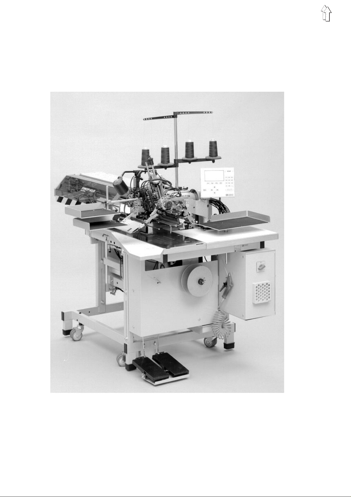
1. Items supplied
–
frame with DC mo to r fo r th e u pp er m ac h i ne ass e mb l y
–
stepping motors for handling material and for the longitudinal
adjustment of th e t r imm i ng de v i c e
–
class 935-246-00 twin-needle double-lockstitch machine
745-26: with component s e t 0 93 5 745304 for joi nt ne ed l e-b ar
switching
745-28:with component set 0935 745307 for separate needle-bar
switching
–
DAC control device
–
reflex light barrier for flap sensing
–
two guide lamps for fabric placement
–
sewing lamp
–
compressed- a i r maintenance uni t wi t h c o mp res s e d- a ir pi s t ol
–
thread pillar
–
trays for it em s to be s ew n on operator’s right and left
–
tools and hard wa r e se t
2. Setting up the sewing machine
Attention!
The sewing machine may only be set up by specialist trained
personnel.
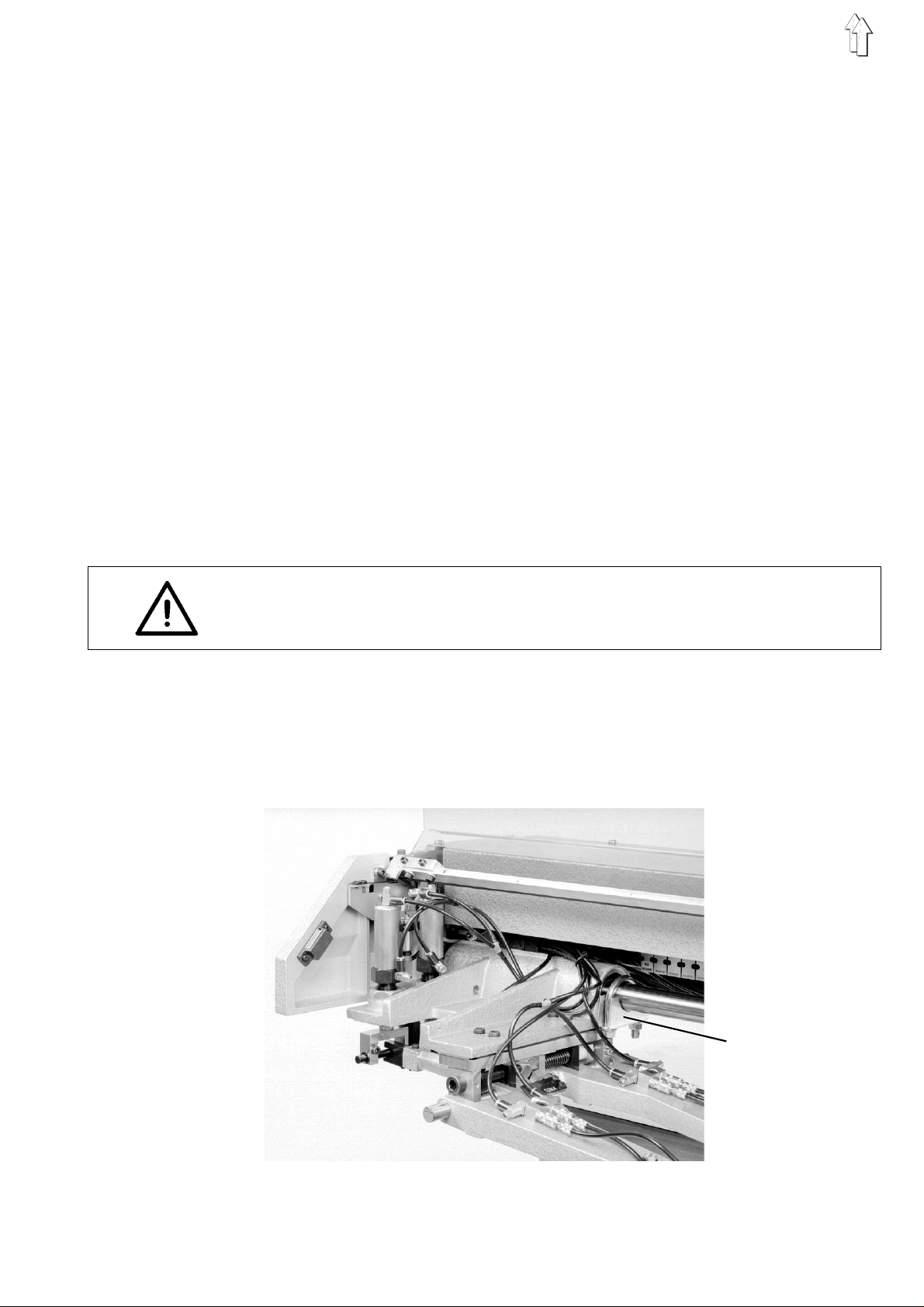
2.1 Removing the carriage safety device
The carriage safety device 1 locks the carriage in its rearmost position.
It must be remo v ed be fo r e t he s ew i ng ma c hi n e i s s e t u p.
1
–
Remove the carriage safety device 1 after undoing the nuts.
3
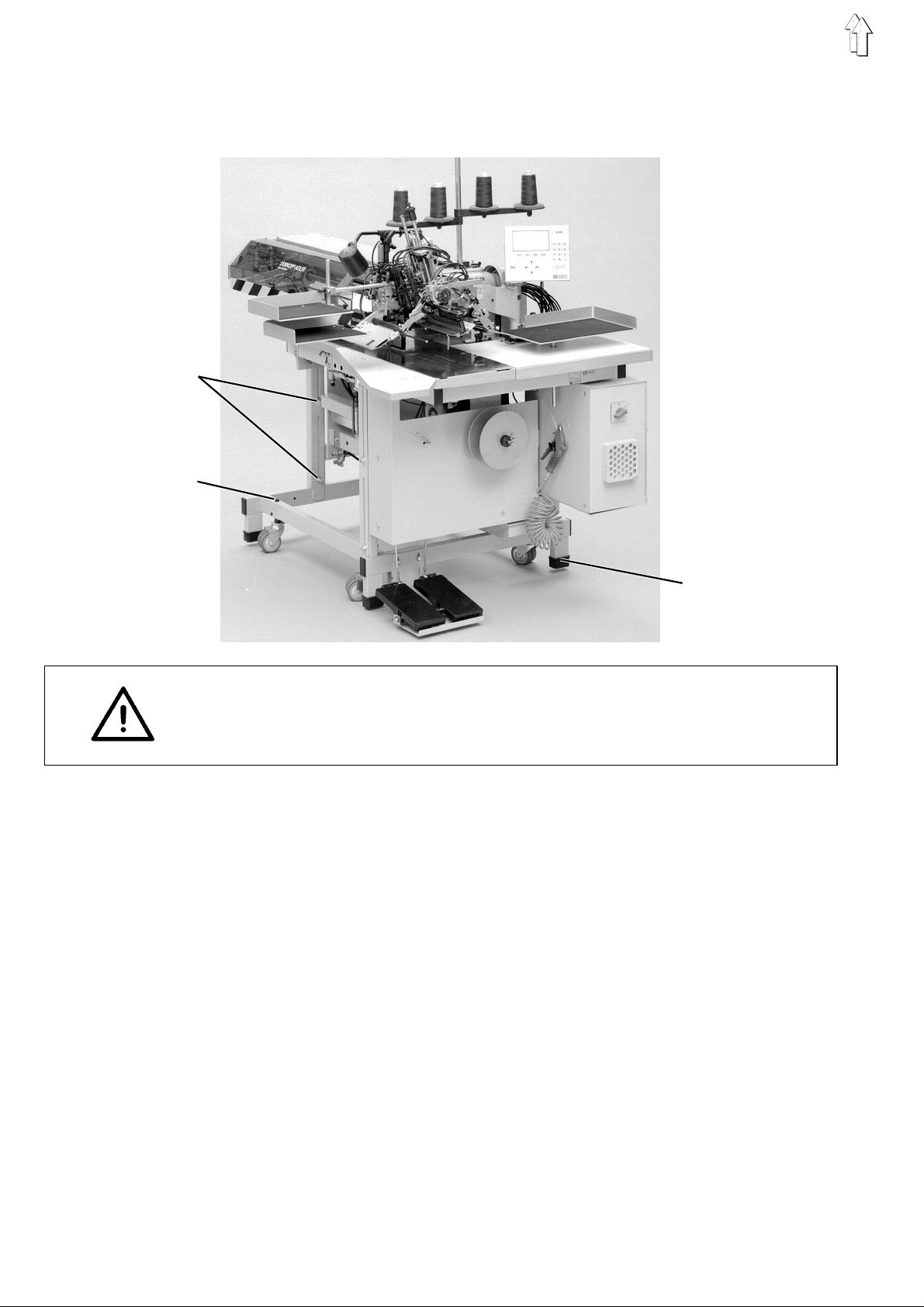
2.2 Movement
The sewing-machine chassis is fitted with four castors for movement
around the plant.
1
2
2.3 Adjusting working height
3
Attention!
Prior to commissioning the sewing machine the sound absorbers 3 (in
the tools and hardware set) must be fitted to the four chassis supports.
Reverse the castors so that the machine is motionless and stable.
–
To move the machine extend the four castors by turning the
adjusting screws 2 to the left.
The chassis s u pp orts must have en ou gh fre e floor space to a l l ow
for movement .
–
After movin g t he s ew i ng ma c hi n e, l ow er i t by t urn i ng th e
adjustment screws 2 to the right.
All four chassis supports must be firmly on the floor.
Working height can be adjusted between 87 and 110 cm (measured to
the top of the t ab l e p l at e) .
It is set to the minimum of 87 cm prior to despatch.
–
Undo locking screws 1 on all four spars of the chassis.
–
Adjust the base plate to the required working height.
To prevent the base p l at e f r om ti l t i ng , p ul l it out (or push it i n) b y
the same amount on both sides.
–
Tighten locking s cr ew s 1.
4
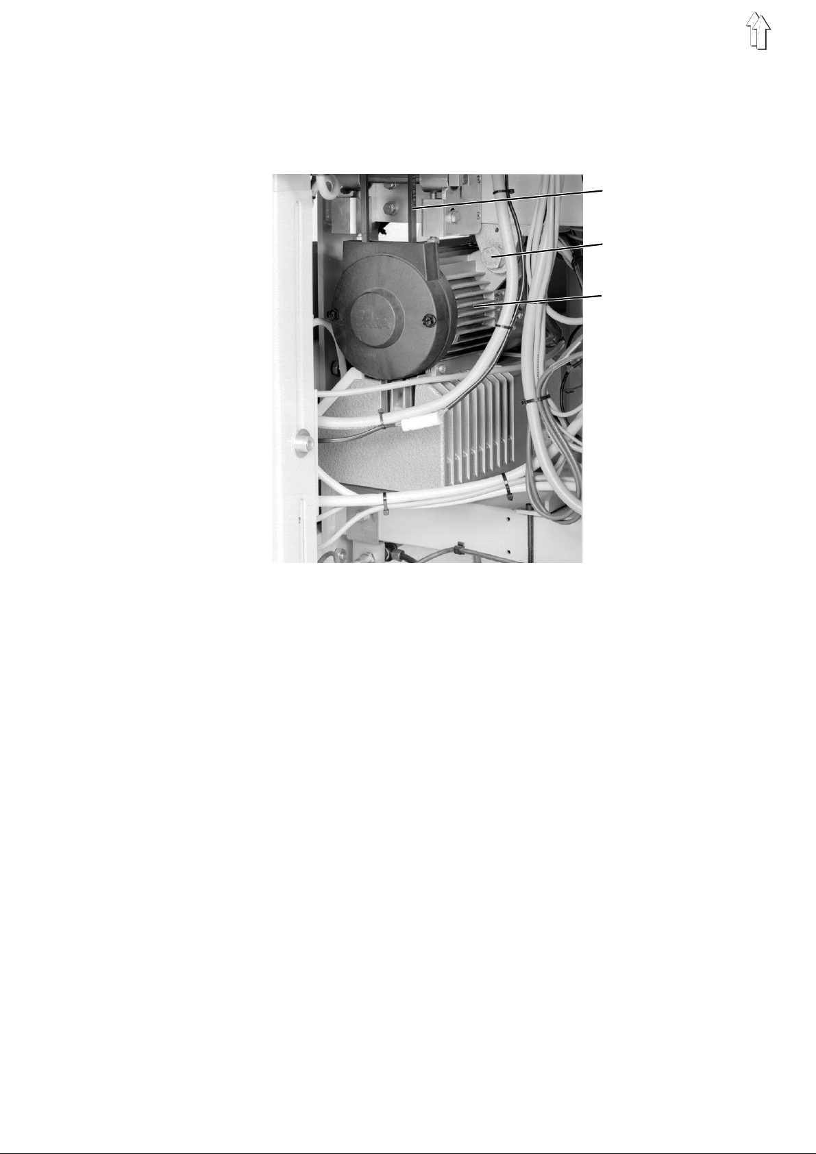
2.4 Checking V -belt tension
When the machine has been moved the V-belt tension (which is
pre-set prior to despatch) must be checked.
When the tension is correct it should be possible to depress the middle
of the V-belt 1 by about 10 mm by pressing on it with a finger.
1
2
3
Correcting V-belt tension:
–
undo screw 2
–
swivel sewing drive 3 until the required V-belt tension is produced
–
tighten scr e w 2
5
3. Attaching fitments removed for despatch
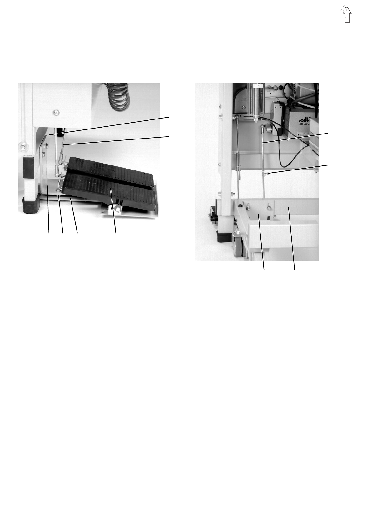
3.1 Pedal
Depending on th e v e rs i on, the sewing machi n e is e qu i pp ed either with
a single peda l or w i th tw o ( ri g ht an d l e ft).
5
1 2 3 4
6
3 5
The pedal 4 is a tt ac h ed to th e lo we r cr oss - m embe r 5:
–
Fix the pedal 4 to the lower cross-member 5 with the bracket 3.
The oblong s l ot s in the bracket 3 e na ble the height to be s l i gh tl y
adjusted.
Adjust the h ei g ht of bracket 3 so th at the pedal 4 can be ea s i ly
operated.
–
The second bracket 1 (supplied) acts as a support.
Attach bracket 1 as shown in the illustrations,
placing the fo ur s e pa rator rings 2 betw ee n b r ac kets 1 and 3.
6
7
–
Fit pedal linkage 6.
–
Slightly loosen locking screw 7.
–
Adjust the he i gh t of the pedal li nk a ge 6 s o th at th e p ed al 4 i s
horizontal when fully depressed.
–
Tighten locking s cr ew 7.
6

3.2 Thread pillar
1
2
3.3 Trays
–
Insert thread pillar 1 into the hole in the table plate and secure it
with nuts 2 and washers.
–
Fit and align thread discs and unwinder arms as shown in the
illustration.
3
4
5
–
Insert trays
–
Tighten locking lever 3.
with rod 5 into locking piece 4 and align.
7

3.4 Folder (working method A)
3
1
4
2
5
6
–
Place Folder
piece 1 as far as it will go.
The pin 3 mus t e nt er o bl o ng s lot 4.
–
Tighten locking s cr ew 2.
The resulting setting will be as pre-set prior to despatch.
6 with span bearing 5 on the m ou nt i ng bo l t o f l o c k ing
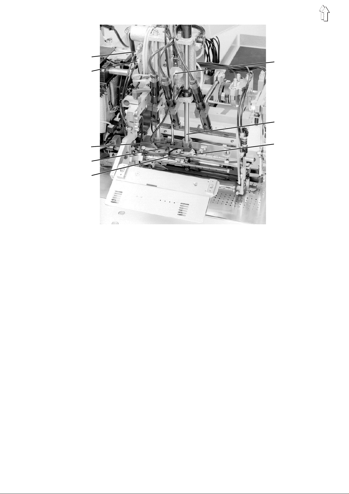
3.5 Folder and gripper-folder (working method B, C)
Fixing the Folder
–
swivel folding unit away to the side
–
place Folde r
–
tighten locking screw 1.
Mounting 2 i n cor p or a te s a ce ntering hole.
Tightening the lo ck i ng s c rew 1 automaticall y b r i ng s ab ou t t he
correct setting.
3 on mounting 2
1
2
3
8
1
6
2
7
3
8
4
5
Fixing the gripper-folder
–
swivel folding unit inwards
–
push gripper-folder with mounting 5 onto rod 7 as far as it will go
The pin 4 must enter oblong slot 3.
–
tighten lo ck i ng s cr ew 8
The resulting setting will be as pre-set prior to despatch.
–
Insert compressed-air connection 6 for needle spreading.
–
With working method C insert compressed-air connections 1 and 2
for braiding c u tt er s .
9

3.6 Ta ble wideners (accessories)
1 2
3
Table widener for trouser seats
–
Attach table widener 1 with screws 2 and the strap located behind
the frame member 3.
–
Slightly loosen the screws on the upper side of the table.
Push table widener 1 to create a gap between it and the table plate.
This gap is n ee ded so that the poc k e t c a n p ass f r ee l y th rou gh
once it has been placed in position.
(order no. 07 94 00 21 51 )
4
5
10
Table widener for jacket fronts
–
Attach table widener 4 to support table with screws 5.
(order no. 0794 002101)

3.7 Stacker (accessory)
1 2 3 4 5
6 7 8
9
10
15
13
14
11
12
13
The throw-over stacker (Order no. Z112 427514) is attached to the
frame of the sewing unit with holder pipe 1.
At deliver y of the sewing unit th e h ol d er pipe 1 is alrea dy p rem ounted
on the frame b rac e 3.
If the throw-o v er s t ac k e r i s de l i ver e d s e pa r at el y p ac k e d, th e h ol d er
pipe 1 must f ir s t b e a tt ac h ed to th e f r am e b r ace 3 of the sewing un i t.
–
Mount guard pla t e 12 on th e h ou s i ng 11 of the throw-o v er s t ac k e r
with screws, washers and spring washers.
–
Fasten holder pipe 1 on the frame brace 3 of the sewing unit with
screws, washers and brackets 6.
–
Fasten spar 4 on the brace 5 of t he s ta c ker s t an d w i th s c rews,
washers and bracket 7.
–
Insert the r i bb ed pl u g 8 i n spar 4.
–
Push the th row - ov e r s ta c k er t oward the frame o f t he s ew i ng un i t s o
that spar 4 ca tc h es i n th e holder pipe 1.
The height of spar 4 is adapted to the holder pipe 1 via the slots in
brace 5 of the s t ac k e r s ta nd .
–
Insert the c ou pl i n g p l ug of th e c o mp r ess e d a i r fe ed i nt o h os e
coupling 10.
–
Insert the c ou pl i n g p l ug of th e c o nt r ol le ad into hose cou pl in g 9.
–
Attach one en d o f t he po te nt i al c a bl e 13 to th e s t op pe r pl a te 14 of
the throw-over s t ac ke r wi t h t he en cl os e d w i ng nu t.
Attach the other end to the frame of the sewing unit with the
existing win g n ut .
The potential cable 13 serves to conduct static charges to ground.
–
After starti n g t he sew i ng un i t w i th th e t hro w- o ver stacker open, set
the clearance to the sewing unit.
The sewing pi e c es must securely e nt er the opening between the
smoother and the stacked-goods support.
–
Tighten clamping lever 2.
11

3.8 Suction devic e (acc essory)
The suction device (order no. 0722 004282) facilitates the exact
positionin g o f m at er i a l s on the working tab l e.
1
2
2 3 4 5
6 7 8
Attention!
Do not reverse hos es 2 an d 5 .
Hose 2 must always be connected to pipe socket 6.
The pneumatically-operated air valve is fitted to pipe socket 6.
–
Lay hose 2 from the settling container 7 to the vacuum-connection
socket 1 of the sewing-machine table.
–
Connect compre s sed - air h ose 3 from cylinder 4 of the air valve to
the Y41 solenoid valve.
–
5
Connect hose 5 to pip e s o c ket 8 o f s e tt l ing c on ta i ne r 7.
Connect other end of hose to on-site vacuum equipment or to the
centrifuga l bl o we r.
Note:
If there is no on-site vacuum equipment a centrifugal blower must
also be ordered.
9
Attention!
It is essential for filter bag 9 to be fitted beneath hose 5.
Filter bag 9 pro te c ts t he v ac u um ge ne rator from being penetrated by
dust and parti c l e s of dirt.
Hoses 2 and 5 mu s t t he r ef or e on no ac count be swapped.
12

4. Electrical connection
Attention!
All work on the electrical e qu i pm en t o f t he s ew i ng ma c hi n e m us t be
carried out by specialist electricians or other appropriately-trained
persons.
The mains pl ug mu s t b e re mo v ed .
4.1 Connecting the DAC operating panel
The DAC operating panel 1 is mounted on the right-hand side of the
machine, see n f r om th e o pe r at or’s viewpo i nt .
1
–
Fit operating panel 1 with clamps 4 and 6 to attachment bracket 5
and adjust angle.
–
Firmly tighten clamping screws on clamps 4 and 6.
Attach pote nt i al c a bl e 3 t o c l a mp 4.
The function of the potential cable is to discharge static charges to
earth.
–
Slightly un do l oc k n ut 7 on attachment bracket 5.
–
Rotate operating panel 1 until the operator has the best possible
view of the d i spl a y.
–
Firmly tighten lock nut 7.
2 3 4 5 6
7
–
Carefully insert plug 2 into the back of the operating panel.
–
Tighten screws of plug 2.
13

4.2 Checking rated voltage
3 - 2 : 190V
3 - 1 : 200V
4 - 2 : 210V
4 - 1 : 220V
5 - 2 : 230V
5 - 1 : 240V
5 4 3 2 1
The rated voltage specifi ed on th e i d en ti f i cation plate mus t c o i nci d e
with the mains voltage.
The sewing ma c hi n e c a n b e a da pt ed to th e l o c al m ai n s vol t ag e b y
means of terminals 1 to 5 on the transformer (see sketch).
230V
The wiring for connection to 3-phase mains supplies is shown in the
terminal co nn ection diagram.
If several D C d r i ves a r e connected these s ho ul d be un i fo rml y
distribute d o v er a l l ph as e s.
14

4.3 Checking positioning
Before the machine is started the positioning set prior to delivery
should be checked.
1 2 3
4 5
Once the main s wi t ch i s t urn ed on th e s e wi n g mac h i ne ad op ts t he
thread-lever-up position.
Caution - danger of injury
Turn off the main swit ch.
Positioning should only be checked or adjusted with the main switch
turned off.
Checking positioning
–
Turn off the main switch.
–
Turn thread lever with handwheel to top dead centre position.
The thread lever must be just commencing its downward
movement.
–
In this position notch 2 on the positioning ring 1 must be in line
with notch 3 on the position indicator 5.
–
Adjust positioning if necessary.
Adjusting positioning
–
Undo clamping screws 4 on positioning ring 1.
–
Rotate positioning ring until notch 2 on it is in line with notch 3 on
position in di cator 5.
–
Firmly tighten clamping screws 4.
15

5. Pneumatic connection
The sewing machine must have a supply of water-free compressed air
to operate its pneumatic components.
Attention!
For the pneuma ti c co ntrol processes t o f unction properl y the
compressed- ai r s u pp l y mu s t b e c o nf i gu red as f ol l o ws :
Even when air consumption is at its peak the op er a ti n g p res s u re m us t
not fall below
If pressure fall-off is excessive:
–
increase compressor power
–
increase diameter of compressed-air lines.
5 bar
.
2
3
1
Connecting compressed-air maintenance unit
–
Connect connection hose 1 (order no. 797 3031) to the
compressed-air supply with a R 1/4" hose connection.
Adjusting operating pressure
–
Operating pressure is
It can be read off pre s s ure ga ug e 3.
–
To adjust operating pressure lift and turn knob 2.
To increase pressure: turn clockwise
To decrease pressure: turn anti-clockwise
Attention!
No compressed air containi ng oi l m us t be ad mi t te d f r om th e a i r sup pl y.
Clean compressed air is taken from behind the filter to clean machine
components and material by air-blasting.
Any oil droplets in the compressed air cause malfunctions and leave
marks on the m at er ia l .
6 bar
.
16

6. Lubrication
NB
Before star ting the machine i t s up pe r as s e mb l y mu st b e su pplied with
oil.
The oil-supply container must be filled only with
lubricating oil.
SP-NK 10 can be obtained from
sales outlets.
Oil-supply container 1 for upper-assembly lubrication
–
Fill oil-supply container 1 with oil through the holes in the sight
glass.
The oil level must be between the "Min." and "Max." marks.
Oil-supply container 3 for gripper lubrication
–
Move upper as s e mb l y of machine to one s i de .
–
Fill oil-supply container 3 with oil through nipple 2 up to the "Max."
mark.
DÜRKOPP ADL ER AG
1
ESSO SP-NK 10
2 3
2
3
17

7. Starting up
<==== REF
–
Turn on main switch .
Control is initialised.
The DÜRKOPP-ADLER logo briefly appears in the operating-panel
display.
–
The control unit checks whether the carriage is in its rearmost
position.
If not, "
–
Depress left-h an d p ed al .
Reference tr a v el co mmences.
The carriage moves to its rearmost position.
Reference travel is necessary to ensure that the carriage is always
in its defi ne d s t ar t i ng po s iti o n.
–
The display ch an ge s to th e se wi n g-m ac h i ne ma i n sc re en .
–
By operatin g t he ap pr o pri a te pedals the vari ou s pl a cem ent stages
are activate d i n seq ue nc e an d se wi n g i s c o mm en c ed.
The individ ual stages depe nd on th e w or k ing method and on th e
configurat i on of th e m ac h i ne .
Attention!
At the commencement of sewing the material must be beneath the
feeding clam ps .
Moving the ca r ri ag e w i th ou t material dama ge s the covering of t he
feeding clam ps .
<====REF
" (reference travel) appears in the display.
–
For the choice of sewing program and further control-unit
adjustment see part 4 ("DAC 745-26/-28: brief description").
–
Placement an d o peration are des c ri be d i n pa r t 1 ( "74 5- 2 6/ - 28 :
operating instructions").
18
 Loading...