

Page 1

Contents Page:
Home
Part 4: Instructions for programming DA-Microcontrol Cl. 745-22; -23; -24
Program-Version: 745-22; -23 = 745 P08; 745-24 = 745 Q01
1. General
2. Description of the Controls
2.1 Keys on the Front Panel . . . . . . . . . . . . . . . . . . . . . . . . . . . . . . . . . . . . . . . . 4
2.2 Internal Switches . . . . . . . . . . . . . . . . . . . . . . . . . . . . . . . . . . . . . . . . . . . . 5
2.3 Display . . . . . . . . . . . . . . . . . . . . . . . . . . . . . . . . . . . . . . . . . . . . . . . . . 6
2.3.1 Display of the 745-22;-23 . . . . . . . . . . . . . . . . . . . . . . . . . . . . . . . . . . . . . . . 6
2.3.2 Display of the 745-24 . . . . . . . . . . . . . . . . . . . . . . . . . . . . . . . . . . . . . . . . . 7
3. Description of the Function Keys
3.1 Setting and Adjusting the Sewing Length . . . . . . . . . . . . . . . . . . . . . . . . . . . . . . 8
3.2 Sewing a Seam Series . . . . . . . . . . . . . . . . . . . . . . . . . . . . . . . . . . . . . . . . 9
3.3 Setting the Piece Counter . . . . . . . . . . . . . . . . . . . . . . . . . . . . . . . . . . . . . . . 10
3.4 Selecting the Positioning Point . . . . . . . . . . . . . . . . . . . . . . . . . . . . . . . . . . . . 10
3.5 Switching the Tape Feed On/Off . . . . . . . . . . . . . . . . . . . . . . . . . . . . . . . . . . . 10
3.6 Switching Tacking On/Off . . . . . . . . . . . . . . . . . . . . . . . . . . . . . . . . . . . . . . . 11
3.7 Selecting the Closing Order of the Flap Clamps . . . . . . . . . . . . . . . . . . . . . . . . . . 11
3.8 Switching the Corner and Center Knives On/Off . . . . . . . . . . . . . . . . . . . . . . . . . . 11
3.9 Switching the Light Barrier On/Off . . . . . . . . . . . . . . . . . . . . . . . . . . . . . . . . . . 12
3.10 Correcting the Seam Beginning and Seam End . . . . . . . . . . . . . . . . . . . . . . . . . . . 12
3.11 Correcting the Corner Knife . . . . . . . . . . . . . . . . . . . . . . . . . . . . . . . . . . . . . . 13
3.12 Tape Length when Sewing with the Light Barrier . . . . . . . . . . . . . . . . . . . . . . . . . . 13
. . . . . . . . . . . . . . . . . . . . . . . . . . . . . . . . . . . . . . . . . . . . . . . . . 3
4. Sewing of Bias Pocket Corners (745-24)
5. Selecting the Sewing and Testing Programs
6. Sewing Progr ams 745-22
6.1 Sewing of Simple, Dual and Asymmetrical Piping . . . . . . . . . . . . . . . . . . . . . . . . . . 17
6.2 Sewing with Automatic Carriage Return . . . . . . . . . . . . . . . . . . . . . . . . . . . . . . . 17
6.3 Sewing with Material Return . . . . . . . . . . . . . . . . . . . . . . . . . . . . . . . . . . . . . 17
6.4 Sewing with Zipper Cutter . . . . . . . . . . . . . . . . . . . . . . . . . . . . . . . . . . . . . . . 18
6.5 Sewing with Zipper Cutter and Automatic Carriage Return . . . . . . . . . . . . . . . . . . . . 18
6.6 Sewing with Zipper Cutter and Material Return . . . . . . . . . . . . . . . . . . . . . . . . . . . 18
7. Sewing Progr ams 745-23
7.1 Sewing of Dual Piping . . . . . . . . . . . . . . . . . . . . . . . . . . . . . . . . . . . . . . . . . 19
7.2 Sewing of Dual Piping with Automatic Carriage Return . . . . . . . . . . . . . . . . . . . . . . 19
7.3 Sewing of Dual Piping with Material Return . . . . . . . . . . . . . . . . . . . . . . . . . . . . . 19
7.4 Sewing of Dual Piping with Piping Reverser . . . . . . . . . . . . . . . . . . . . . . . . . . . . . 20
7.5 Sewing of Dual Piping with Piping Reverser and Automatic Carriage Return . . . . . . . . . . 20
7.6 Sewing of Single Piping with Piping Reverser . . . . . . . . . . . . . . . . . . . . . . . . . . . 20
7.7 Sewing of Single Piping with Piping Reverser and Automatic Carriage Return . . . . . . . . . 21
7.8 Sewing of Asymmetrical Piping with Piping Reverser . . . . . . . . . . . . . . . . . . . . . . . 21
7.9 Sewing of Asymmetrical Piping with Piping Reverser and Automatic Carriage Return . . . . . 21
7.10 Sewing of Simple and Asymmetrical Piping without Piping Reverser . . . . . . . . . . . . . . . 22
. . . . . . . . . . . . . . . . . . . . . . . . . . . . . 14
. . . . . . . . . . . . . . . . . . . . . . . . . . . 16
Page 2

7.11 Sewing of Simple and Asymmetrical Piping without Piping Reverser
with Automatic Carriage Return . . . . . . . . . . . . . . . . . . . . . . . . . . . . . . . . . . . 22
7.12 Sewing of Simple and Asymmetrical Piping without Piping Reverser
with Material Return . . . . . . . . . . . . . . . . . . . . . . . . . . . . . . . . . . . . . . . . . 22
8. Sewing Programs 745-24
8.1 Sewing of Dual Piping . . . . . . . . . . . . . . . . . . . . . . . . . . . . . . . . . . . . . . . . 23
8.2 Sewing of Dual Piping with Automatic Carriage Return . . . . . . . . . . . . . . . . . . . . . . 23
8.3 Sewing of Dual Piping with Material Return . . . . . . . . . . . . . . . . . . . . . . . . . . . . 23
9. Aid Programs
9.1 Center Knife Adjustment . . . . . . . . . . . . . . . . . . . . . . . . . . . . . . . . . . . . . . . 24
9.2 Setting the Bobbin Thread Counter (745-22;-23) . . . . . . . . . . . . . . . . . . . . . . . . . 24
9.3 Changing the Positioning Point Manual / Automatic . . . . . . . . . . . . . . . . . . . . . . . . 24
9.4 Testing the Piping Reverser for Dual Piping (745-23) . . . . . . . . . . . . . . . . . . . . . . . 25
9.5 Testing the Piping Reverser for Simple Piping (745-23) . . . . . . . . . . . . . . . . . . . . . . 25
9.6 Testing the Piping Reverser for Asymmetrical Piping (745-23) . . . . . . . . . . . . . . . . . . 25
10. Setting Programs
10.1 Testing the Positioning Procedure for Dual Piping (745-23) . . . . . . . . . . . . . . . . . . . 26
10.2 Loading of standard values . . . . . . . . . . . . . . . . . . . . . . . . . . . . . . . . . . . . . 26
10.3 Setting the Remaining Thread Monitor(Light Reflection Barriers) . . . . . . . . . . . . . . . . 26
10.4 Testing the Zipper Cutter (745-22) . . . . . . . . . . . . . . . . . . . . . . . . . . . . . . . . . 27
10.5 Checking Needle und Center Knife Actuation . . . . . . . . . . . . . . . . . . . . . . . . . . . 27
10.6 Testing the Positioning Procedure (745-23) . . . . . . . . . . . . . . . . . . . . . . . . . . . . 28
10.7 Setting the Light Barrier for Seam Beginning/Seam End . . . . . . . . . . . . . . . . . . . . . 28
10.8 Setting the Material Strip Reverser (745-23) . . . . . . . . . . . . . . . . . . . . . . . . . . . . 29
11. Testing Programs
11.1 Program Version and Check-Sum Display . . . . . . . . . . . . . . . . . . . . . . . . . . . . . 30
11.2 Checking the Step Motor Control . . . . . . . . . . . . . . . . . . . . . . . . . . . . . . . . . . 30
11.3 Checking the Seriel Interface . . . . . . . . . . . . . . . . . . . . . . . . . . . . . . . . . . . . 31
11.4 Testing the Memory and Timer . . . . . . . . . . . . . . . . . . . . . . . . . . . . . . . . . . . . 31
11.5 Checking Continuity . . . . . . . . . . . . . . . . . . . . . . . . . . . . . . . . . . . . . . . . . 32
11.6 Checking the Front Panel Elements . . . . . . . . . . . . . . . . . . . . . . . . . . . . . . . . . 32
11.7 Checking the Input Elements . . . . . . . . . . . . . . . . . . . . . . . . . . . . . . . . . . . . 33
11.8 Selecting Input Elements . . . . . . . . . . . . . . . . . . . . . . . . . . . . . . . . . . . . . . . 34
11.9 Selecting Output Elements . . . . . . . . . . . . . . . . . . . . . . . . . . . . . . . . . . . . . . 35
11.10 Sewing Drive: Pedal Operation . . . . . . . . . . . . . . . . . . . . . . . . . . . . . . . . . . . 36
11.11 Positioning the Machine Head in the 2nd Needle Position/Revolution Test . . . . . . . . . . . 36
11.12 Positioning the Machine Head in the 1st Needle Position . . . . . . . . . . . . . . . . . . . . . 37
11.13 Positioning the Machine Head with Cutting Revolutions . . . . . . . . . . . . . . . . . . . . . 37
11.14 Positioning the Machine Head and Thread Trimming . . . . . . . . . . . . . . . . . . . . . . . 37
12. Function Displays and Error Messages
12.1 Displays for Operating Aids . . . . . . . . . . . . . . . . . . . . . . . . . . . . . . . . . . . . . 38
12.2 Displays by Malfunctions . . . . . . . . . . . . . . . . . . . . . . . . . . . . . . . . . . . . . . . 39
12.3 Error Messages . . . . . . . . . . . . . . . . . . . . . . . . . . . . . . . . . . . . . . . . . . . . 40
13. Step Motor Output
13.1 Programing Switches on the Front . . . . . . . . . . . . . . . . . . . . . . . . . . . . . . . . . 41
13.2 Displays on the Front . . . . . . . . . . . . . . . . . . . . . . . . . . . . . . . . . . . . . . . . . 41
Page 3
1. General
MICROCONTROL
The
-24
include the integrated comprehensive
monitoring system.
A microcomputer assumes the control tasks, monitors the sewing
process and s i gn al s o pe rating faults an d m al f un c ti o ns.
Special programs facilitate mechanical adjustments and make
possible a ra pi d te s ti n g o f t he input and output elements wi th ou t
additional m ea s ur i n g a pp ara tus.
Errors and test results are shown in a 2 x 16 digit display.
Under normal working conditions the display shows information to
operation and the sewing process.
When an operating error or malfunction occurs the functions are
interrupted . The cause is sho wn i n t he di s p l ay b y t he app rop r i at e err o r
symbol.
In most cases the error symbol will disappear when the cause of the
fault has been remedied.
In some cases the main switch must be turned off during error
correction for safety reasons.
A portion of the error messages are meant only for the service
personnel.
All functions can be called up and changed by pressing the
appropriate key. The unit must be in its initial position for this.
When the uni t i s s w i tc h ed on th e c o nt r ol s c o nd uc t s ev e ral
comprehensive self-tests. Among other things the program and data
memories and the display are checked for flawless operation at this
time.
After the ma chi n e i s s w i tc h ed off th e s e t va l ue s of th e i n div i d ua l
functions ar e sto r ed i n t he pro gr a m a nd da ta me mo ri es (b at te r y
buffered) and aut om at i c all y a c tiv a te d w he n s w i tc h ed on
again.
controls of the
DÜRKOPP ADLER 745-22;-23;
MULTITEST
testing and
ATTENTION !
The controls for the Class
for the Class
Controls
Controls
745-22;-23
745-22;-23:
745-24:
Parts no. 985 0 745030
.
Parts no. 9850 745040
745-24
are
not
compatible with the controls
3
Page 4
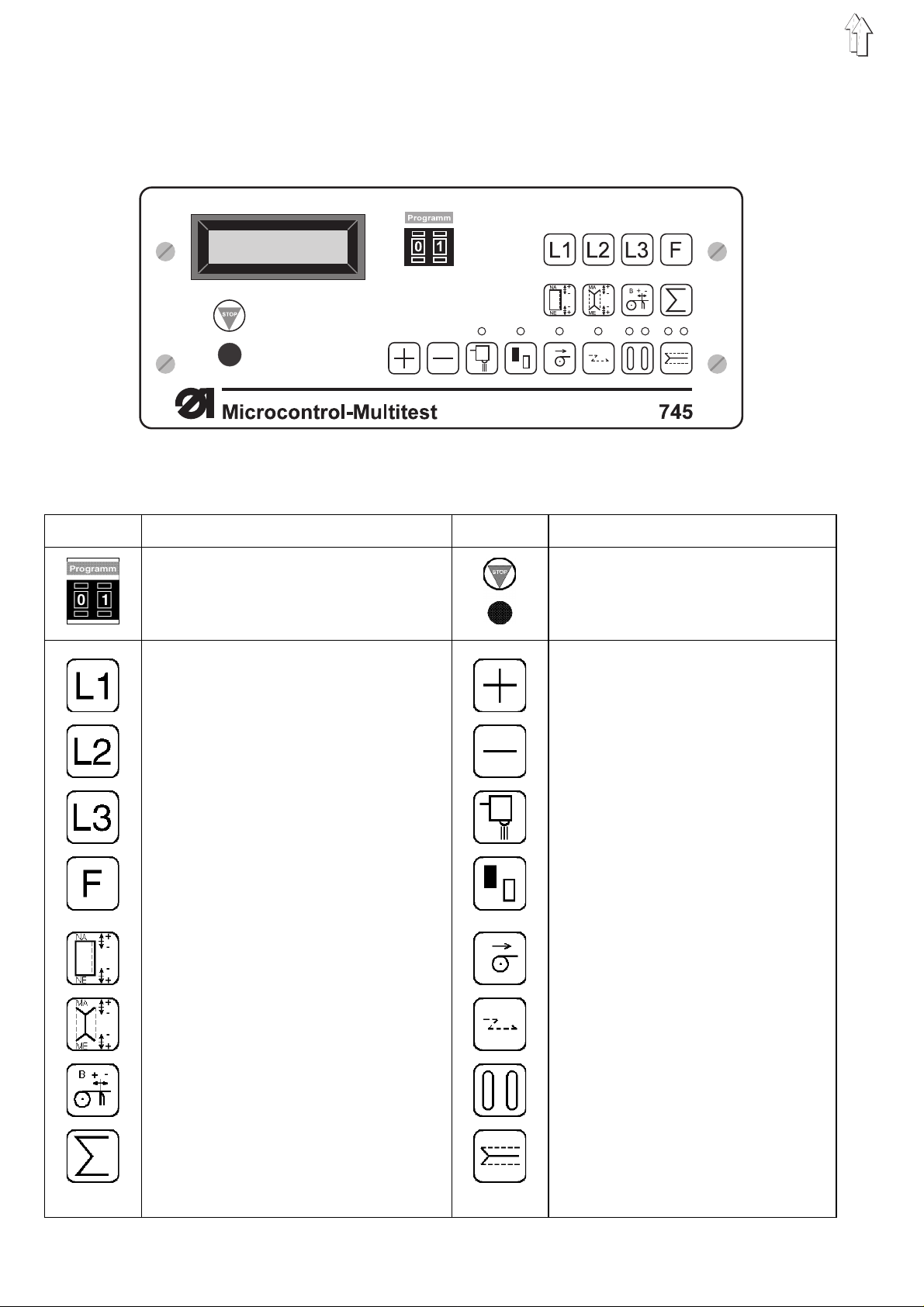
2. Description of the Controls
2.1 Keys on the Front Panel
Key Function Key Function
Selecting Se wi n g an d Testing Programs
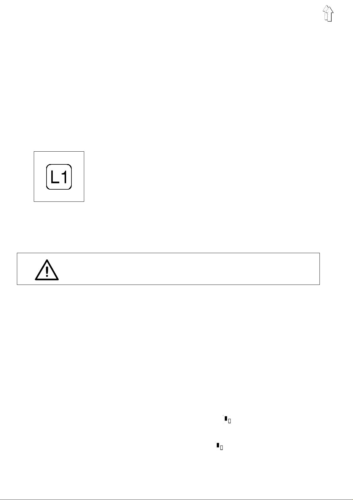
Sewing Leng th L1
Sewing Leng th L2
Sewing Leng th L3
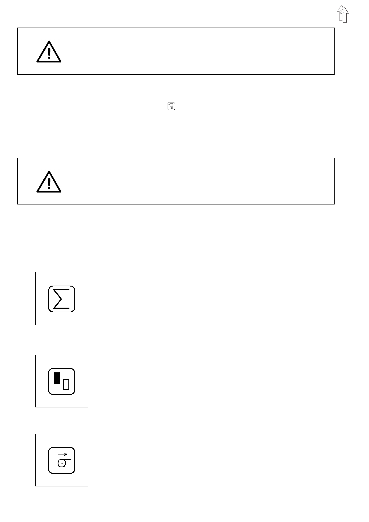
Sewing a Se am S eri e s
Correcting of Seam Beginning/End when
Sewing Flaps wi t h L igh t b ar ri e r
Correcting th e C orn er K n iv es a t
Seam Beginning and Seam End
Stopping th e C ur re nt P r og ram,
Activating a Selected Program
Increase Parameter Value
Decrease Parameter Value
Light Barrier On
Selecting the Positioning Point
Tape Feed On/Off
Tacking On/Off
Setting Tape Length when Sewing wi th
Light Barrier
Setting the Counter
4
Selecting the Closing Order of the
Flap Clamps
Center Knife an d C orn er Kn i fe
On/Off
Page 5
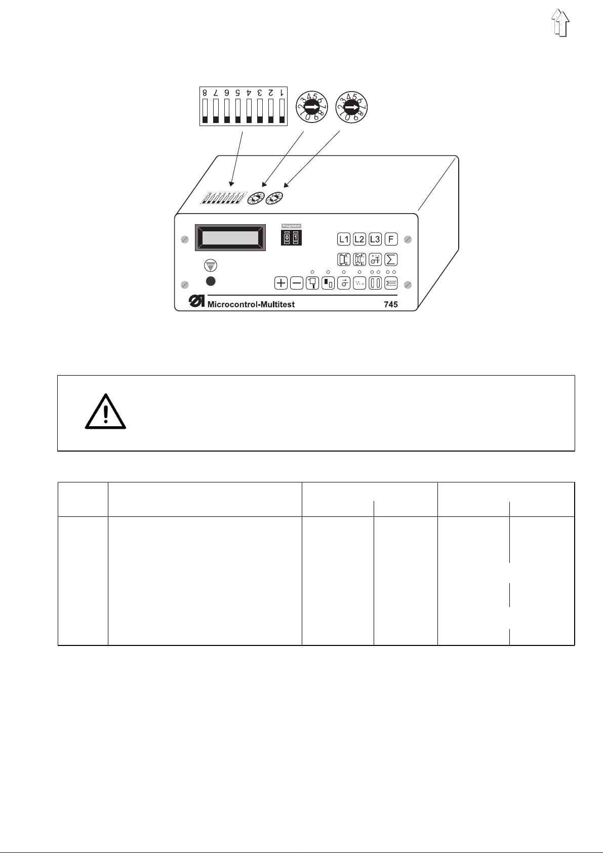
2.2 Internal Switches
DIP-Schalter
on
off
b417 b401 b40 2
In the control behind the display there are three pre-selector switches
for setting certain machine parameters.
CAUTION !
The switches are only evaluated once when the sewing unit is turned
on.
After changing a switch setting switch the main switch off and then on
again or oper at e t he
DIP-Switch b417:
b417 Function OFF ON OFF ON
.1 Stitch Leng th 2,5 mm 3,2 mm 2,5 mm 3,2 mm
.2 Stitch Cond ensation Stit c h L en gt h 0,8 mm 1,4 mm 0,8 mm 1,4 mm
.3 Maximum Sewing Length 180 mm 200 mm 180 mm 200 mm
.4 Thread Monitor ON OFF No function
.5 Locking Vacuum (b8 / s14) OFF ON OFF ON
.6 Late Opening of the Flap Clam ps OFF ON OFF ON
.7 with Re verser Dev ice OFF ON N o funct ion
.8 Continuous Op er a ti o n OFF ON OFF ON*
(only in combination with .4 "OFF")
* Thread monitor is turned off
745-22;-24
745-23
Dial b401: Dial b402:
Sewing Revolutions Operation Mode of the Left Transport Clamp
b401 = 1 250 0 1 /m i n b402 = 0 No fun c ti o n
b401 = 2 275 0 1 /m i n b402 = 1 Lower le ft transport cl am p
b401 = 3 300 0 1 /m i n separately
: b417.7 = OF F
: b417.7 = ON (with Reverser Device)
STOP
key.
745-22;- 23 745-24
b402 = 2 Lower left transport clamp with the
right
5
Page 6
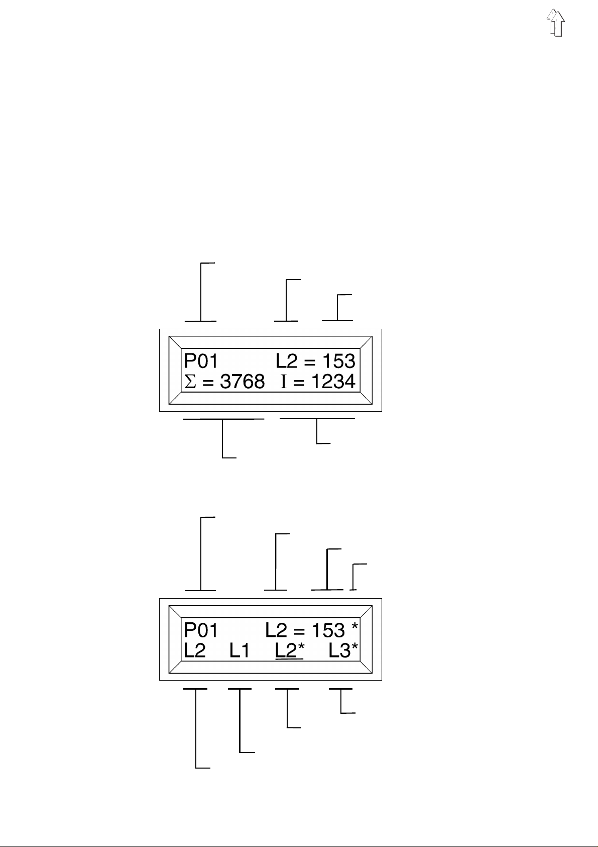
2.3 Display
2.3.1 Display of the 745 -22;- 23
The Microcontrol is equipped with a 2 x 16-digit display.
It shows the program number, sewing lengths, bobbin thread reserve
and piece cou nt . B y o pe r at i ng err o r s or m al f un c ti o ns the functions are
interrupted an d t he c au s e s h ow n b y th e a pp r op ri at e e r ror s ymbol.
The operatio na l rea di n es s o f t he s ew i ng un i t i s shown by having th e
current param et er s i n th e d i spl a y. The setting s are the same as those
last selected before the machine was switched off.
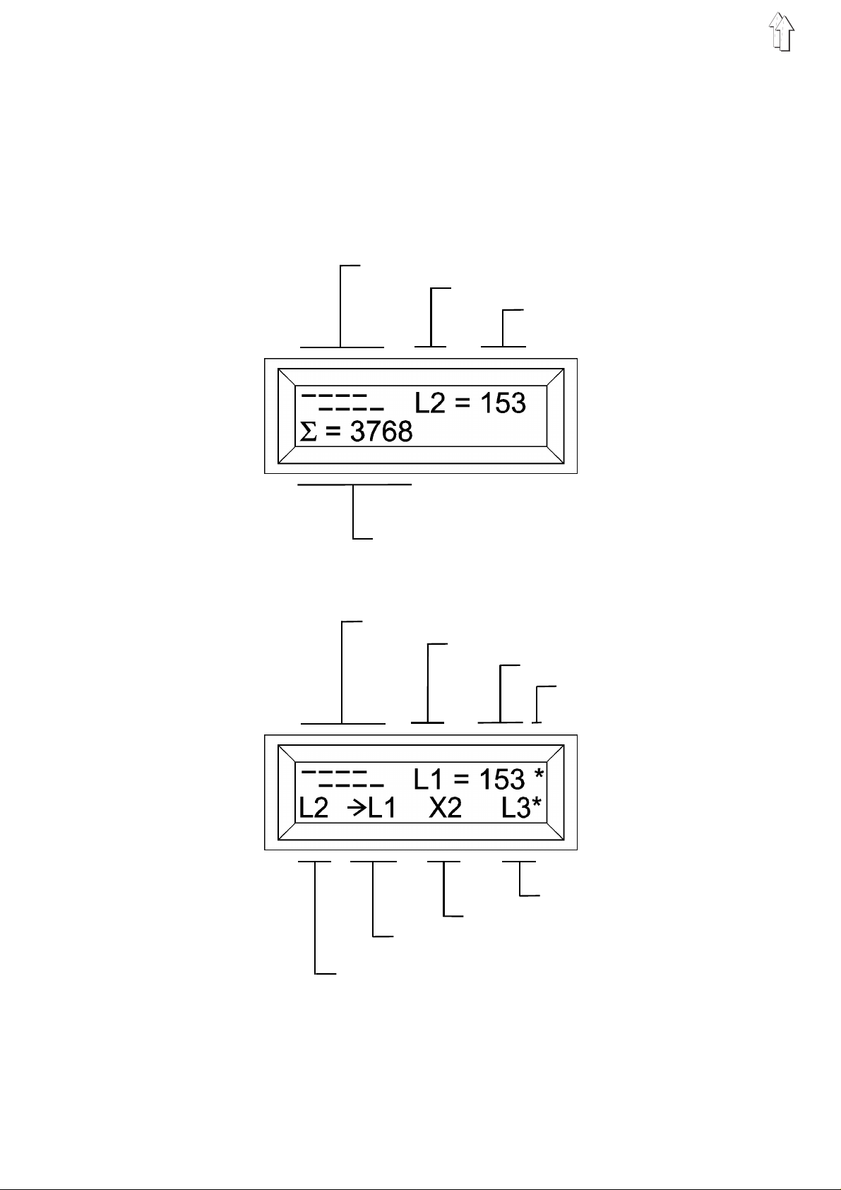
Display example 1: With selected sewing length
Program numb er
Selec ted sew ing len gth
Stored se wing le ngt h in mm
Bobbin th rea d reserve
Piece counter
Display example 2: With programmed length series
Program numb er
Current sewi ng l eng th
Stored le ngt h in mm
The n stack ing
4. Length to be sewn
3. Length to be sewn
(Current sew ing dis tance i s un derlin ed)
2. Length to be sewn
1. Length to be sewn
6
Page 7
2.3.2 Display of the 745-24
With the
in the right h al f of the first lin e o f the display.
Through this s y m bo l the seamstress c an es t ab l i s h w hi c h bi a s ha s
been set for th e c u r r en tl y selected progra m.
The "=====" symbol, for example, denotes straight pocket corners at
the seam beginning and seam end.
Display example 1: With selected sewing length
Bias p ocket o pening s
Selec ted sew ing len gth
Stored se wing le ngt h in mm
745-24
a symbol for th e b i as o f t he c or n er i n c is i on s ap pears
Piece counter
Display example 2: With programmed length series
Bias p ocket o pening s
Current sewi ng l eng th
Stored le ngt h in mm
The n stack ing
4. Length to be sewn
3. Length to be sewn ( here: L igh t barrier s eam)
2. Length to be sewn
(The arrow marks the current sewing length)
1. Length to be sewn
If the display remains blank after the main switch has been turne d
on, then the 1,6 A fuse(on the underside of the mains unit) is to be
replaced.
7
Page 8
3. Description of the Function Keys
The values for the various functions can be set as follows:
–
Call up the desi r e d f un cti o n b y pre s si ng th e a pp rop r i at e f un cti o n
key.
The function will be shown in the display with a blinking cursor.
–
Change the set v a lue wi t h t he "+ / -" keys.
–
Press the same function key again.
The change i s com pl e te d.
The unit is rea dy t o s t ar t ag ai n .
3.1 Selecting and Changing Sewing Length
With the L1, L2 and L3 keys three sewing lengths stored in memory
can be selected. A change of the sewing length can only occur before
the feed procedure has begun.
–
Select the stored sewing length by pressing the key L1, L2 or L3.
The select ed sewing length is s h ow n i n th e r ig ht half of the fir s t
display line.
–
If "L?" appears in th e d i s pl a y, then a sewing length without an
allowable value in memory was selected.
Enter an allo wa bl e v alu e w i th th e "+/-" keys or select a different
sewing length.
–
Change the set s e win g l e ng th wi t h t he "+/-" keys.
–
Press the function key (L1, L2 or L3).
The set sewing length will be stored in memory.
It will remain in memory until it is changed again.
–
For further details see chapter 5 and 6 ("Sewing Programs").
CAUTION !
When changing the sewing length L1 it is essential that the corner
knife inter val a l s o b e a l te r ed at th e s a me ti m e.
Setting the Corner Knife Interval
That sewing le ng th wh i ch i s m ost of te n s e wn s houl d be s to red un de r
L1.
The interval be tween the corner k n i v es m ust be set so that i t i s th e
same as the sewi n g l e ng th sto r ed un de r L1 .
With all other sewing lengths the corner incision occurs seperately in
two strokes . A f te r th e i nci s i o n of the fi r st c or n er k ni f e th e ma te r i al i s
transported to the second corner knife.
Exception:
With Class
together.
Positioning the Material
–
With short se ams under 75 mm place the materi al a t t he fo rw a rd
positioning point.
–
If, by sewing lengths under 75 mm, the rear positioning point is
chosen, then the error message "
display. You must the n ch an ge to the forward po s iti o ni n g po i nt .
–
With placing at th e r e ar p os it i on i ng po int th e following cond iti o n
must be satisfied:
Otherwise the error message "
display. You must the n ch an ge to the forward po s iti o ni n g po i nt .
745-23
the corner knives must always be switched on or off
ERROR
L1 - L2(L3) < 50
ERROR
" will appear in the
" will appear in the
8
Page 9

3.2 Sewing of a Seam Series
With the aid of the "F" key a stored series of up to four seams can be
called up.
745-22;-23
745-24
Calling up the Series
–
Call up the series by pressing the key "F".
The series is shown in the lower display line.
The current sewing length has a special marking:
745-22;-23:
745-24:
The current sewing length with the appropriate value in millimeters
is shown in the right half of the upper display line (see display
example 2).
–
A star "*" behind a se wi n g l e ng th me an s th at s ta c k i ng occ u r s after
this length is sewn.
Without stac k i n g t he ma te r ial i s t r an spo r te d b ac k t o t he fe ed ar e a
after sewing .
Then the next se wi n g le ng th i s au to ma tic a l l y ac t i vat ed .
–
Using the "+/-" keys any desired sewing length in the series can be
activated.
Key "+": Cursor to the right
Key " -": Cursor to the left
–
To exit from the series press the keys L1, L2 or L3.
The approriate sewing length (L1, L2 or L3) is activated.
–
To exit form the series with the
The light barrier seam is activated.
:The series can be made up of any desired order of the
three sewing l e ng th s L1, L2 and L3.
: The series can be made up of any desired order of the
sewing lengths L1, L2, L3 and the light barrier seam s
LX2
LX3
and
The current sewing length is underlined (e.g.
The current sewing length is preceded by an arrow
(e.g.
.
"->L1"
).
745-24
press the key " ".
"
L2"
LX1
,
).
Programming a New Series
The values f or t he pr o gr a mm ed s ew i ng l en gt hs m us t established
before enteri ng the se ri es mo de (se e " S el e c ting and Adjustin g th e
Sewing Leng th " ).
–
Press and hold the key "F".
–
At the same time press the key "-".
The previous series is erased.
–
By pressing the keys L1, L2 and L3 up to four sewin g l e ng th s c an
be entered in t he de s i red or d er.
–
745-24 only:
After selecting a sewing length the following functions
can be set for this length using the appropriate keys:
Light Barri er O n / Off
Positioning Point
Tape Feed On / Off
Tacking On / Off
Closing Order of the Flap Clamps
Corner and Center Knives On / Off
9
Page 10
CAUTION !
The functions set with the keys only valid for the sewing program
the series mode
The settings h ave no effec t on th e s e win g p r og ram m b ey o nd th e
series mode .
–
745-24
"Σ" key.
–
745-24
Press the " " key until the desired light barrier seam
X3
appears in th e d i s pla y.
Set the des ir ed fu nc t i on s fo r th e s e l ec t ed s ew i ng l en gh t u s i ng th e
keys listed on page 9.
Confirm with the "Σ" key.
–
After selecting a sewing length (L1, L2 or L3) stacking after this
sewing leng th c an be pr o gra mmed by pressin g t he "+" key.
CAUTION !
With the
must first b e confirmed with th e "Σ" key.
Then stacking after this sewing length can be programmed by pressing
the "+" key.
–
–
745-24
By pressing th e "-" key the last entry is erased.
To start the series press the key "F" again.
The first sewi n g l e ng th i s au to ma ti c a ll y set .
.
: E a c h e nt r y of a sewing length mu s t b e c o nf i rme d with the
: Programming the light barrier seam
the selection of th e s e wi n g le ng th an d t he fu nc t i on s
LX1, LX2 or LX3
X1, X2
in
:
or
3.3 Setting the Piece Counter
By pressing this key the piece counter is reset to
The current pi e c e c o un t i s s h ow n i n th e l e ft half of the lower display
line. The pi ec e cou nter shows the n um be r of pieces made sin c e th e
last resetting of the counter.
3.4 Selecting the Positioning Point
Depending on th e t y pe of s ew i ng pi e c es the feed occurs at th e forward
or rear posit i on i ng po i nt .
By pressing th i s key t he positioning poi n t i s c h an ge d.
If the LED abov e t he k ey i s l i t th en th e f orward positionin g p oi n t w as
selected.
The changeover between manual and automatic alteration of the
positionin g p oi n ts o cc ur s i n pr o gr a m P 4 2.
3.5 Switching the Tape Fe ed On/Of f
0000
.
10
By pressing this key the tape feed is switched on and off.
If the LED above this key is lit then the tape feed is switched on.
Page 11
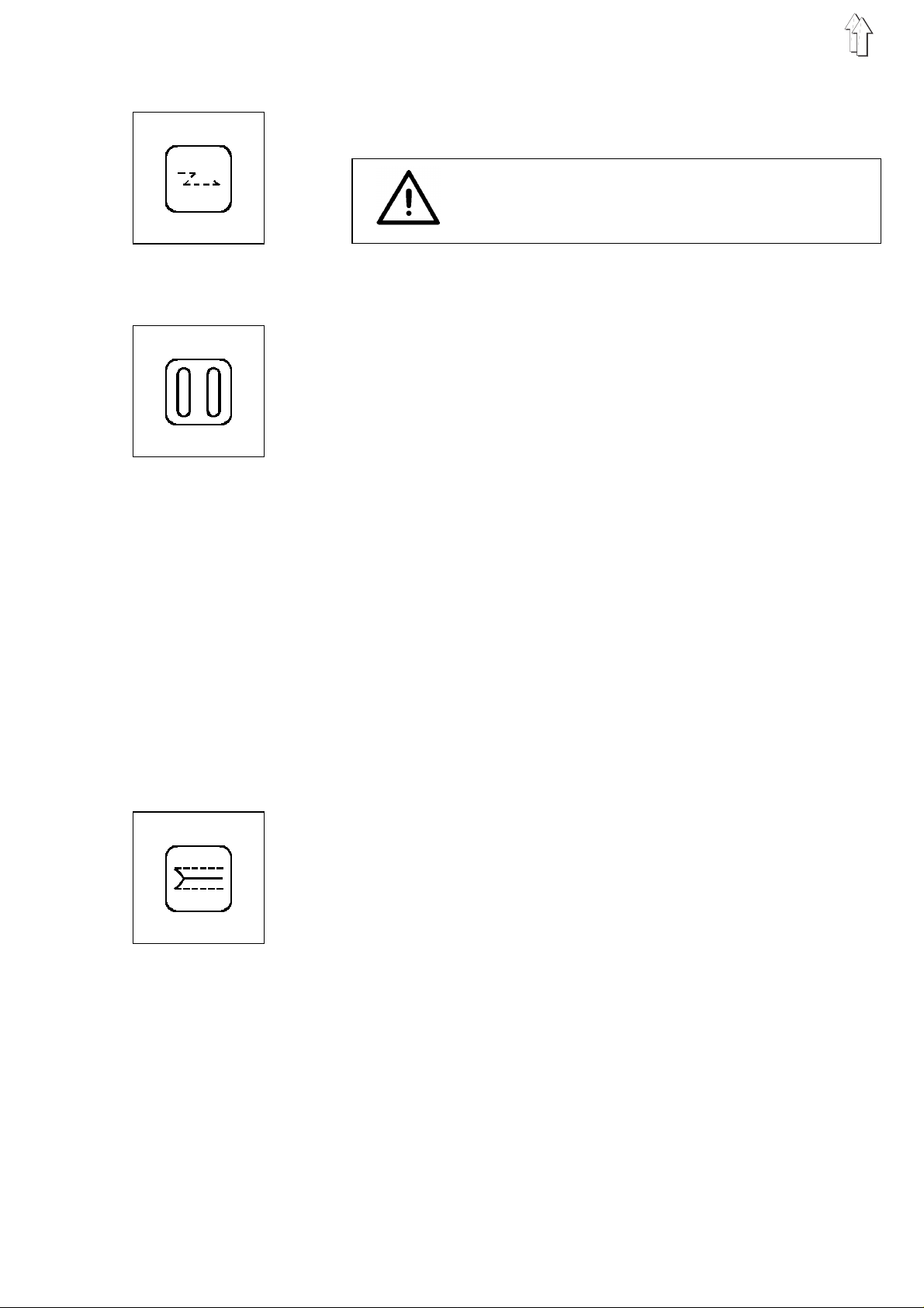
3.6 Switching Tacking On/Off
By pressing this key tacking is switched on and off.
If the LED above the key is lit then tacking is switched on.
CAUTION !
With 1.4 mm stitch length in stitch condensation
tacking is generally switched off.
3.7 Selecting the Closing Order of the Flap Cl amps
With this key the order of the closing of the flap clamps can be set.
In sewing pro gr a ms P07 to P12 the ord er o f t he c l osi n g o f the flap
clamps cann ot be s et .
Operating the key switches between four possibilities.
The order is s h ow n b y th e t wo LE Ds above the ke y:
–
Both LEDs lit:
The flap clamps close at the same time.
–
Only the left LED is lit:
First the lef t flap clamp clo s es , th en th e r i g ht .
–
Only the right LED is lit:
First the ri gh t f l ap c lamp closes, then the left.
–
Both LEDs are off:
Operation without flap clamps (optimally timed procedure).
The timing for the opening of the flap clamps in the feed area is
establishe d b y th e s e tt i ng of th e p r ese l ec t or switch b417.6 i ns i d e t he
controls (see "Internal Switches"):
–
–
OFF
In the
lowers.
In the ON setting the flap clamps open after the folder lowers.
setting the flap clamps open af te r the transport cl a s p
3.8 Switching the Corner and Center Knives On/Off
With this key the corner knives or the center and corner knives can be
switched on and off.
In sewing pro gr a ms P07 to P12 the cor n er a nd the center kni v es
cannot be switched off.
Operating the key switches between three possibilities.
The different s et ti n gs a re s h ow n b y th e t w o LE D s ab ov e th e k e y:
–
Both LEDs are l i t:
Corner and ce nt er k n i v es are switched on.
–
Only the right LED is lit:
The corner kn i ves a r e switched off.
–
Both LEDs are off:
All knives are switched off.
11
Page 12
3.9 Switching On the Light Barrier
By pressing this key the light barrier is switched on.
The light barrier recognizes the seam beginning and seam end on
flaps.
The light barrier cannot be activated in the operating modes for piping
reversing and zippers.
–
–
CAUTION !
When sewing w ith th e l i g ht ba rr i er, the flap mus t be pl a ced
the two positi o nin g p oi n ts .
If the flap i s po s i ti o ne d i n front of the forw ard or e x te nd s beyond the
rear positioning point, the error message
Press the key.
The lit LED ab ov e th e k e y si gn al s , th at th e l i g ht ba r r ier i s s witched
on.
745-22;-23:
745-24:
To switch off the l i g ht ba r ri er press one of the k e y s L1, L2 or L3.
Instead of t he s ew i ng l en gt hs
shows "LX".
Through repeated pressing of the key, the display
shows the li g ht ba r r ier s e am s
sequence.
"LS"
L1, L2, L3,
LX1, LX2
appears in the display.
the display
LX3
and
between
in
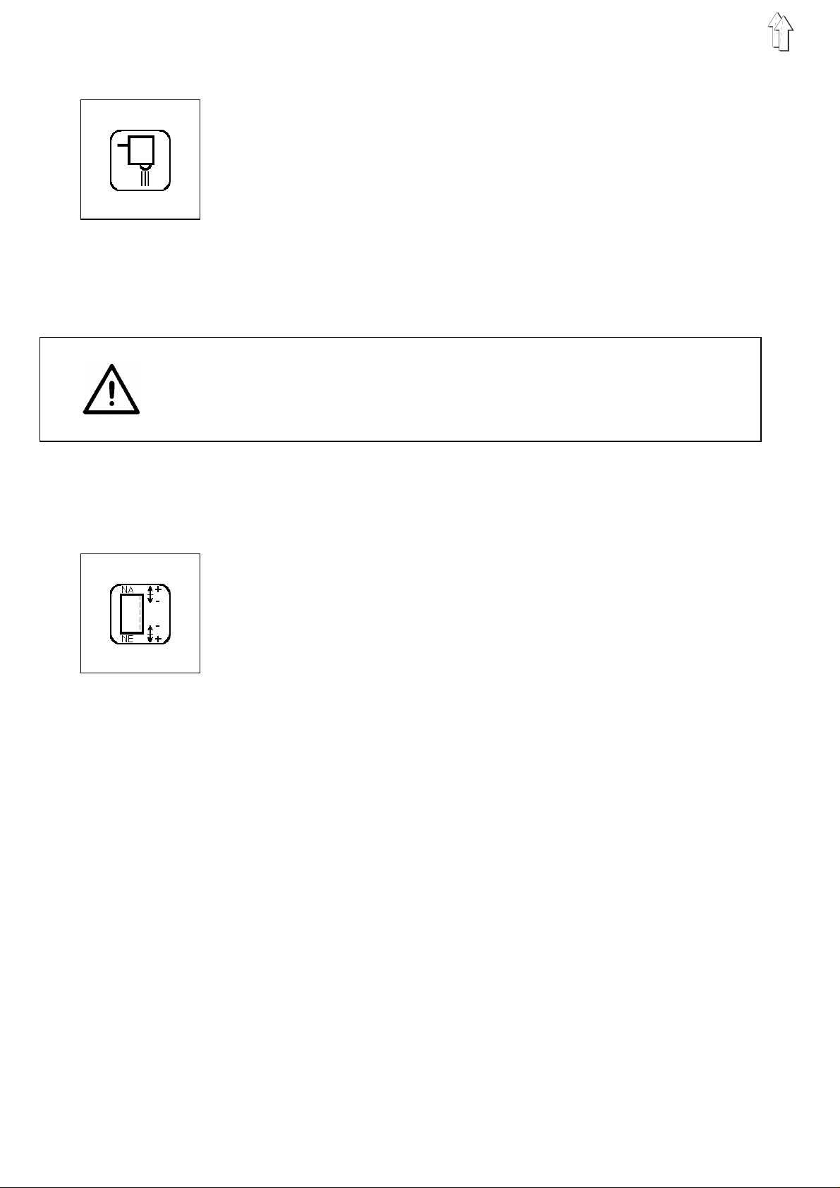
3.10 Correcting the Seam Beginning and Seam End
This key calls up the correction function for seam beginning and seam
end.
The correcti o n o f s e am be gi n ni n g (NA) and seam en d (NE) occurs for
the sewing leng th s
(745-22;-23) and
By changing th e v a lue s fo r NA and NE th e c o rne r k ni f e a cti o n i s
appropriately adjusted for sewing with the light barrier.
–
Press the fu nction key.
The set values for NA and NE are shown in the display.
–
Increase or decrease the value for NA in steps by pressing the
"+/-" keys.
Minimum: 0
Maximum: 99
Median valu e: 50 (no correc ti o n)
Step distance: 1 cycle = 0.085 mm
–
Press the function key again.
This s wit che s from N A t o NE .
–
Increase or decrease the value for NE in steps by pressing the
"+/-" keys.
–
Complete the correction procedure by calling up the selected
sewing length.
L1, L2, L3
LX1, LX2, LX3
and for the li g ht ba r ri er s e am s
(745-24).
LX
12
Page 13
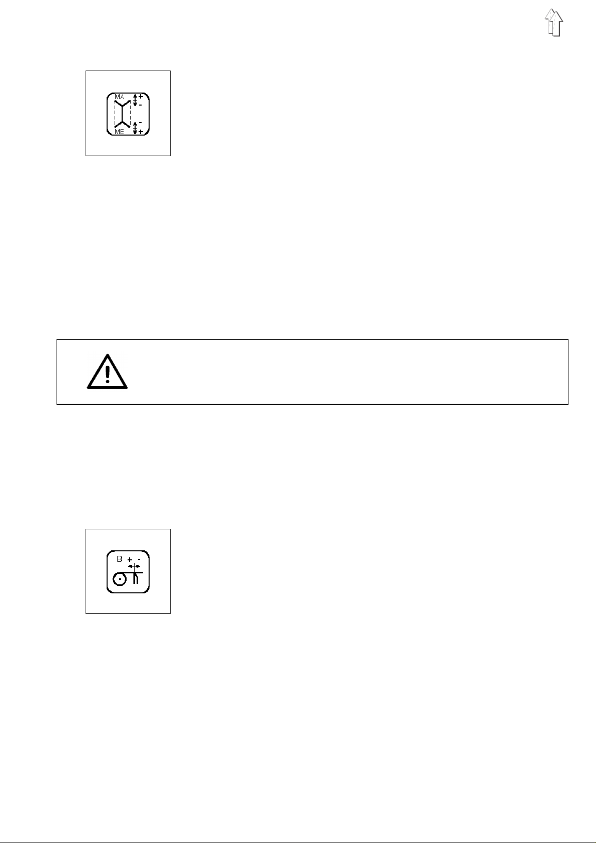
3.11 Correcting the Corner Knives
This key calls up the correction function for the corner knives at the
seam beginning (MA) and the seam end (ME).
The correction can be made for the sewing lengths
as for the light barrier seams
(745-24).
–
–
–
–
–
L1, L2, L3
LX
(745-22;-23) and
Press the function key.
The set values for MA and ME will be shown in the display.
Increase or decrease the value for MA in steps by pressing the
"+/-" keys.
Minimum: 0
Maximum: 99
Median value: 50 (no correction)
Step distance: 1 cycle = 0.085 mm
Press the function key again.
This switch es f r om MA to ME.
Increase or decrease the value for ME in steps by pressing the
"+/-" keys.
Complete the correction procedure by calling up the selected
sewing length.
LX1, LX2
as well
and
LX3
CAUTION !
With the
together.
Set the parame te r s MA and ME at th e m ed i an v alu e 50.
Special note for 745-23:
When sewing with piping reverser only sewing length L1 can be set.
745-23
the corner knives must always be switched on or off
3.12 T ape Length when Sewing wi th Light Barrier
This key sets th e t ap e le ng th at th e s e am en d w he n s e wi n g w ith l i gh t
barrier.
The set valu e co r r esp on ds t o the distance f rom the initial po si ti o n o f
the transport c la s ps t o cu tt i ng .
–
Switch on th e t ap e f ee d.
–
Press the function key.
The set valu e f or the tape length i s s h ow n i n th e d i s pl a y.
–
Increase or decrease the tape length in steps by pressing the
"+/-" keys.
Minimum: 20 mm
Maximum: 1 00 mm
Step distance: 1 cycle = 1 mm
–
Complete the setting procedure by calling up the selected sewing
length.
13
Page 14

4. Sewing of Bias Pocket Corners (745-24)
The bias poc ket c or n ers r e sul t fr o m t he off set between the lef t a nd th e
right seam row.
The desired seam offset is programmed separately at the control unit
for the seam be gi n ni n g (
If all parame te r s ar e s et to th e m ed i an v al u e
pocket results.
Parameters for the programming of the bias pocket corners:
Seam begi nni ng Seam e nd
BR ER
1 ... 10 ... 20 1 ... 10 ... 20
Right seam
Left seam
1 ... 10 ... 20 1 ... 10 ... 20
L EL
B
BR,BL
) and the seam en d (
"10"
, then a strai g ht
ER,EL
).
Programmin g e xam pl e :
and seam end (Seam offset = 2 stitches)
Seam beginning Seam end
BR = 9 ER = 9
1 ... 10 ... 20 1 .. 10..20
Right seam
Left seam
1 ... 10 ... 20 1 . 10..20
BL = 11 EL = 11
Seam offset Parameter to be set (Seam beginning)
[Stitches] Right seam Left seam
2BR
4BR
6BR
• •
• •
• •
16 BR
18 BR
Bias pocket corners at the seam beginning
Seam offset = 2 stitches
= 10 - 1 =
= 10 - 2 =
= 10 - 3 =
= 10 - 8 =
= 10 - 9 =
9BL
8BL
7BL
2BL
1BL
= 10 + 1 =
= 10 + 2 =
= 10 + 3 =
•
•
•
= 10 + 8 =
= 10 + 9 =
11
12
13
18
19
14
Page 15

Display exam ple : S t r aig ht pocket corners
BL = Beginnin g- le ft needle
BR = Beginnin g- ri g ht ne ed l e
ER = End-right ne edle
EL = End-left needle
Selec ted sew ing distance
Programming the bias of the pocket corners:
–
Simultaneo us l y p res s t he k ey f or t he desired sewi ng di s t an c e (L1,
L2
or L3) and the " " ke y.
–
For selecting a light barrier seam:
Press the " " k ey u nt i l th e d es ir e d l i g ht ba r ri er s e am
LX3
or
Simul taneou sly press the " " an d th e " " key s.
–
The parameters for the programmed bias of the selected sewing
distance appear in the display (see display example).
–
Increase or decrease the parameter values in steps by pressing
the "+/-" keys.
appears in th e d i s pla y.
LX1, LX2
Minimum: 1
Maximum:20
Median value : 1 0 ( s t rai g ht pocket corner)
Steps: 1 step = 1 stitch of the current stitch condensation
Attention!
The left and r i gh t s e am rows must always be offs et an equal
number of sti tc h es w i th r ef ere nc e to th e m edian value "10".
The parameters BR and BL to be set for the desired seam offset
can be found in the table on page 14.
The parameters ER and EL are arrived at in the same manner.
–
Press the "Σ" key.
The cursor moves to the next parameter.
–
Complete the setting procedure by pressing the key for the
selected sewing distance L1, L2, L3 or the " " k ey ( for light
barrier seam s ).
ATTENTION !
bias
With
conducted:
–
pockets the fo l l ow i ng ad dit i on al s e tt ing wo r k mu s t b e
Manually adjust the angle and height of the corner knives
according to the programmed seam offset (see Operating
Instructions)
or:
Switch the corner knives off via the " " key on the controlunit.
15
Page 16

5. Selecting the Sewing and T esting Programs
The sewing an d t es t i ng pr o gra ms l i s t ed be l ow c an be s el e cted with the
Program
"
–
–
–
–
Switch Program Function Subclass
00
P00
Display of th e P r o gra m Version
" preselecto r s wi t c h.
Set the "
Switch on the main switch or press the key "
The desired p r og r am i s ac t i v at ed .
If the symbol "P?" appears in th e ri ght half of the fir s t di s p l ay l i n e,
then an illegal program number was selected.
A sewing procedure running at the time the "
operated will be cancelled.
Correct the se tt ing an d p r ess t he "
Program
" switch to the desired program.
STOP
STOP
STOP
" switch.
745-22 745-23 745-24
XXX
".
" key was
01
02
03
04
05
06
07
08
09
10
11
12
13
14
15
40
41
42
43
44
45
46
47
51
52
53
54
55
56
57
58
59
60
61
62
63
64
65
66
67
68
69
P01
P02
P03
P04
P05
P06
P07
P08
P09
P10
P11
P12
P13
P14
P15
P40
P41
P42
P43
P44
P45
P46
P47
P51
P52
P53
P54
P55
P56
P57
P58
P59
P60
P61
P62
P63
P64
P65
P66
P67
P68
P69
Sewing program
as P01, with au to ma ti c c a rr iag e r e tu rn
as P01, with mate rial re tu rn
as P01, wi th zi pp er c u tt er
as P04, with au to ma ti c c a rr iag e r e tu rn
as P04, with mate rial re tu rn
as P01, with piping reverser for dual piping
as P07, with mate rial re tu rn
as P01, with piping reverser for simple piping
as P09, with au to ma ti c c a rr iag e r e tu rn
as P01, with piping reverser for asymmetr. piping
as P11, with material return
as P01 without piping reverser for
as P02 asymmetrical piping and
as P03 simple piping
Center knife adjustment
Setting the bobbin thread counter
Changing th e p os i t i on i ng po i nt ma nu al / au to ma ti c
Testing the pi p i ng rev e r ser f or d ua l pi p ing
Testing the pi p i ng rev e r ser f or si m pl e pi p i ng
Testing the pi p i ng rev e r ser f or a s ymm etrical pipin g
Testing the po s i tioning procedur e ( d ua l pip i ng )
Loading of standard values
Setting th e re ma i ni n g t hr e ad mo ni t or
Testing the z i pp er c u tt er
Checking th e n eedle and center kn i fe ac t ua ti o n
Testing the po s i tioning procedur e ( si m pl e pi p i ng )
Setting th e li g ht barrier for se am be gi n ni n g/ en d
Setting the material strip reverser
Checking th e s t ep mo tor control
Checking th e s e r i al i n te r fa c e
Testing the timer and memory
Checking continuity
Checking th e front panel el em en ts
Checking th e i n pu t e l em en ts
Selecting input elements
Selecting ou tp ut el e me nts
Sewing driv e: pe da l op era ti o n
Sewing driv e: set v al u e X , po si ti o n 2
Sewing driv e: set v al u e X , po si ti o n 1
Sewing drive: set value X, position 1, position 2
Sewing drive: set value X, position 2,
with thread trimming proc ed ure
XXX
XXX
XXX
X
X
X
X
X
X
X
X
X
X
X
X
XXX
XX
XXX
X
X
X
X
XXX
XXX
X
XXX
X
XXX
X
XXX
XXX
XXX
XXX
XXX
XXX
XXX
XXX
XXX
XXX
XXX
XXX
XXX
16
Page 17

6. Sewing Programs 745-22
6.1 Sewing of Simple, Dual and Asymmetri cal Piping
–
Turn the DIP-Switch
–
Turn on main switch.
<---REF
"
–
Step back on th e l e ft pedal.
The transport clasps are raised.
The transport carriage runs to its rear position.
–
The display signals start readiness by showing the current
parameters (see display example 1).
The settings correspond to the last settings selected before the
machine was t ur n ed off.
–
Set the "
–
Press the "
The program is activated.
–
By tapping the left pedal bring the carriage return out of the hold
position, s wi t c h o n t he fe ed pr o c ed ure and start.
–
By stepping back on the left pedal during the feed procedure the
previous steps can be activated again.
–
By stepping back on the left pedal the sewing process can be
interrupted af te r st a rti n g.
–
When the sewi n g u nit i s eq uip pe d w i th a r ig ht pe da l th i s ac t i v at es
the holder and the vacuum.
When the sewing unit is equipped with a knee switch this operates
the vacuum.
" appears in the lower display line.
Program
STOP
b417.7
" switch to "01".
" key.
in switch setting "
OFF
".
6.2 Sewing with Automatic Carriage Return
–
Turn the DIP-Switch
–
Set the "
–
Press the "
The program is activated.
In contrast to P01:
–
After stacking the transport clasps are automatically run back to
the feed area.
Program
6.3 Sewing with Material Return
–
Turn the DIP-Switch
–
Set the "
–
Press the "
The program is activated.
In contrast to P01:
–
There is no s ta c k i ng af te r s ewing.
–
The material is transported back to the feed area by the transport
clasps.
Program
STOP
STOP
b417.7
" switch to "02".
" key.
b417.7
" switch to "03".
" key.
in switch setting "
in switch setting "
OFF
OFF
".
".
17
Page 18

6.4 Sewing with Zipper Cutter
–
Turn the DIP-Switch
–
Set the "
–
Press the "
The program i s ac t i vated.
In contrast to P01:
–
After sewing the sewn zipper is cut off.
–
The material i s g en er a l ly pl a c ed at th e r e ar p os i t i on i ng po i nt .
–
The shortest sewing length is 75 mm.
–
The light barrier cannot be activated.
Program
STOP
b417.7
" switch to "04".
" key.
in switch setting "
6.5 Sewing with Zipper Cutter and Automatic Carriage Retur n
–
Turn the DIP-Switch
–
Set the "
–
Press the "
The program i s ac t i vated.
In contrast to P04:
–
After stacking the transport clasps are automatically run back to
the feed are a.
–
The light barrier cannot be activated.
Program
STOP
b417.7
" switch to "05".
" key.
in switch setting "
OFF
OFF
".
".
6.6 Sewing with Zipper Cutter and Mater ial Return
–
Turn the DIP-Switch
–
Set the "
–
Press the "
The program i s ac t i vated.
In contrast to P04:
–
After sewing there is no stacking.
–
The material i s t r an s po rte d b ac k t o t he fe ed ar e a b y th e t r an s po rt
clasps.
–
The light barrier and the flap clamp cannot be activated.
Program
STOP
" switch to "06".
" key.
b417.7
in switch setting "
OFF
".
18
Page 19

7. Sewing Programs 745-23
7.1 Sewing of Dual Piping
–
Turn the DIP-Switch
–
Turn on main switch.
<---REF
"
–
Step back on th e l e ft pedal.
The transport clasps are raised.
The transport carriage runs to its rear position.
–
The display signals start readiness by showing the current
parameters (see display example 1).
The settings correspond to the last settings selected before the
machine was t ur n ed off.
–
Set the "
–
Press the "
The program is activated.
–
By tapping the left pedal bring the carriage return out of the hold
position, s wi t c h o n t he fe ed pr o c ed ure and start.
–
By stepping back on the left pedal during the feed procedure the
previous steps can be activated again.
–
By stepping back on the left pedal the sewing process can be
interrupted af te r st a rti n g.
–
When the sewi n g u nit i s eq uip pe d w i th a r ig ht pe da l th i s ac t i v at es
the holder and the vacuum.
When the sewing unit is equipped with a knee switch this operates
the vacuum.
" appears in the lower display line.
Program
STOP
b417.7
" switch to "01".
" key.
in switch setting "ON".
7.2 Sewing of Dual Piping with Automatic Carr iage Return
–
Turn the DIP-Switch
–
Set the "
–
Press the "
The program is activated.
In contrast to P01:
–
After stacking the transport clasps are automatically run back to
the feed area.
Program
STOP
b417.7
" switch to "02".
" key.
7.3 Sewing of Dual Piping with Material Return
–
Turn the DIP-Switch
–
Set the "
–
Press the "
The program is activated.
In contrast to P01:
–
There is no s ta c k i ng af te r s ewing.
–
The material is transported back to the feed area by the transport
clasps.
Program
STOP
b417.7
" switch to "03".
" key.
in switch setting "ON".
in switch setting "ON".
19
Page 20

7.4 Sewing of Dual Piping with Piping Reverser
–
Turn the DIP-Switch
–
Set the "
–
Press the "
The program i s ac t i vated.
In contrast to P01:
–
After the corner incision the pipings are reversed and the material
overlaps a re d r aw n t hr o ug h t he i nc i si o n.
–
The light barrier and the flap clamp cannot be activated.
–
Only one sewing length L1 can be activated.
Program
STOP
b417.7
" switch to "07".
" key.
in switch setting "ON".
7.5 Sewing of Dual Piping with Piping Rever ser and Automatic Carr iage Return
–
Turn the DIP-Switch
–
Set the "
–
Press the "
The program i s ac t i vated.
In contrast to P07:
–
After stacking the transport clasps are automatically run back to
the feed are a.
Program
STOP
b417.7
" switch to "08".
" key.
in switch setting "ON".
7.6 Sewing of Simple Piping with Pipi ng Reverser
Presupposition:
–
Turn the DIP-Switch
–
Set the "
–
Press the "
The program i s ac t i vated.
In contrast to P01:
–
After the corner incision the piping is reversed and the material
overlap of the piping and the right material strip is drawn through
the incision.
–
Before this op eration the left transport cla sp i s removed aside.
–
The light barrier and the flap clamp cannot be activated.
–
Only one sewing length L1 can be activated.
Optional equ i pm en t
for simple p ipi n g) required.
Program
STOP
" switch to "09".
" key.
b417.7
0792 030901
in switch setting "ON".
(Reverser device
20
Page 21

7.7 Sewing of Simple Piping with Piping Reverser and Automatic Carr iage Return
–
Turn the DIP-Switch
–
Set the "
–
Press the "
The program is activated.
In contrast to P09:
–
After stacking the transport clasps are automatically run back to
the feed area.
Program
STOP
b417.7
" switch to "10".
" key.
7.8 Sewing of Asymmetrical Piping wi th Piping Reverser
–
Turn the DIP-Switch
–
Set the "
–
Press the "
The program is activated.
In contrast to P01:
–
After the co r ne r i nc i si o n t he pipings are r eversed and the ma te ri al
overlaps are drawn through the incision.
–
Before this operation the left transport clasp is removed aside.
–
The light ba r ri er a nd th e f l ap c lamp cannot be act i v at ed .
–
Only one sewi n g le ng th L1 c an be ac t iv at ed .
Program
STOP
b417.7
" switch to "11".
" key.
in switch setting "ON".
in switch setting "ON".
7.9 Sewing of Asymmetrical Piping with Piping Reverser and Automatic Carriage Return
–
Turn the DIP-Switch
–
Set the "
–
Press the "
The program is activated.
In contrast to P11:
–
After stacking the transport clasps are automatically run back to
the feed area.
Program
STOP
b417.7
" switch to "12".
" key.
in switch setting "ON".
21
Page 22

7.10 Sewing of Simple and Asymmetrical Piping without Piping Reverser
–
Turn the DIP-Switch
–
Set the "
–
Press the "
The program i s ac t i vated.
–
The running of the program is suitable to sewing program
Program
STOP
b417.7
" switch to "13".
" key.
in switch setting "ON".
7.1 1 Sewing of Simple and Asymmetrical Piping without Pi ping Reverser
with Automatic Carriage Return
–
Turn the DIP-Switch
–
Set the "
–
Press the "
The program i s ac t i vated.
–
The running of the program is suitable to sewing program
Program
STOP
b417.7
" switch to "14".
" key.
in switch setting "ON".
P01
P02
.
.
7.12 Sewing of Simple and Asymmetrical Piping without Piping Reverser
with Material Return
–
Turn the DIP-Switch
–
Set the "
–
Press the "
The program i s ac t i vated.
–
The running of the program is suitable to sewing program
Program
STOP
b417.7
" switch to "15".
" key.
in switch setting "ON".
P03
.
22
Page 23

8. Sewing Programs 745-24
8.1 Sewing of Dual Piping
–
–
–
–
–
–
–
–
–
Turn on main switch.
<---REF
"
Step back on th e l e ft pedal.
The transport clasps are raised.
The transport carriage runs to its rear position.
The display signals start readiness by showing the current
parameters (see display example 1).
The settings correspond to the last settings selected before the
machine was t ur n ed off.
Set the "
Press the "
The program is activated.
By tapping the left pedal bring the carriage return out of the hold
position, s wi t c h o n t he fe ed pr o c ed ure and start.
By stepping back on the left pedal during the feed procedure the
previous steps can be activated again.
By stepping back on the left pedal the sewing process can be
interrupted af te r st a rti n g.
When the sewi n g u nit i s eq uip pe d w i th a r ig ht pe da l th i s ac t i v at es
the holder and the vacuum.
When the sewing unit is equipped with a knee switch this operates
the vacuum.
" appears in the lower display line.
Program
STOP
" switch to "01".
" key.
8.2 Sewing of Dual Piping with Automatic Carr iage Return
–
Set the "
–
Press the "
The program is activated.
In contrast to P01:
–
After stacking the transport clasps are automatically run back to
the feed area.
Program
STOP
" switch to "02".
" key.
8.3 Sewing of Dual Piping with Material Return
–
Set the "
–
Press the "
The program is activated.
In contrast to P01:
–
There is no s ta c k i ng af te r s ewing.
–
The material is transported back to the feed area by the transport
clasps.
Program
STOP
" switch to "03".
" key.
23
Page 24

9. Aid Programs
9.1 Center Knife Adj ustment
Program P40 alters the incision of the center knife.
If a higher value is selected the incision moves to the outside at the
seam beginning and at the seam end.
With a smaller value the incision moves in the seam.
–
Set the "
–
Press the "
The program i s ac t i vated.
The lower left display line shows the current value for the center
knife incision.
–
Correct the set value with the "+/ -" keys.
Program
STOP
" switch to "40".
" key.
9.2 Setting the Bobbin Thread Counter (745-22;-23)
With the sub-classes
monitored by a c o un td ow n c o un te r.
The setting of t hi s co un te r is ma de wi t h p rog r am P41 .
–
Set the "
–
Press the "
The program i s ac t i vated.
The lower disp l ay li n e s h ow s th e p res e t va l ue .
The positi on to be s et bl i n ks .
–
Set the desired value for each of the positions with the "+/ -" keys.
–
The next higher position is selected with the key "Σ".
–
By operatin g b ot h k e y s " + " an d " -" a t t he s am e t i me th e c o un te r i s
reset to "
Setting the value "0000" causes the bobbin thread monitor to
be shut off by the counter.
Program
STOP
0000
745-22
" switch to "41".
" key.
".
and
745-23
the bobbin thread is
Note:
The set value multiplied by factor four is approx. the number of
possible stitches.
9.3 Changing the Positioning Point Manual/Automatic
Program P42 switches over between manual and automatic changing
of positioni n g p oi n t.
An automatic change is only possible when sewing a sewing length.
–
Set the "
–
Press the "
The program i s ac t i vated.
The set stat us i s s h ow n i n th e display.
–
The switch o v er b et w e en ma nu al a nd au to ma ti c c h an ge i s made
with key "Σ".
Program
STOP
" switch to "42".
" key.
24
Page 25

9.4 T esting the Piping Reverser for Dual P iping (745-23)
Program P43 corresponds to sewing program P07.
During the reversing procedure there is a stop after each step.
–
Set the "
–
Press the "
The program is activated.
–
After the fi r s t st ep of the draw-th r ou gh pro c ed ur e th e p r oce s s i s
stopped.
–
By pressing the "+" key the process is continued to the next stop
point.
Program
STOP
" switch to "43".
" key.
9.5 T esting the Piping Reverser for S imple Piping (745-23)
Program P44 corresponds to sewing program P07.
During the reversing procedure there is a stop after each step.
–
Set the "
–
Press the "
The program is activated.
–
After the fi r s t st ep of the draw-th r ou gh pro c ed ur e th e p r oce s s i s
stopped.
–
By pressing the "+" key the process is continued to the next stop
point.
Program
STOP
" switch to "44".
" key.
9.6 Testing the Piping Reverser for Asymmetrical Piping (745-23)
Program P45 corresponds to sewing program P11.
During the reversing procedure there is a stop after each step.
–
Set the "
–
Press the "
The program is activated.
–
After the fi r s t st ep of the draw-th r ou gh pro c ed ur e th e p r oce s s i s
stopped.
–
By pressing the "+" key the process is continued to the next stop
point.
Program
STOP
" switch to "45".
" key.
25
Page 26

10. Setting Programs
10.1 T esting the Positioning Procedur e for Dual Piping (745-23)
Program
–
–
–
–
–
–
10.2 Loading of standard values
Program
Correction seam beginning (NA) / seam end (NE): 50
Correction of corner knife seam beginning (MA) / seam end (ME): 50
745-24: Seam beginning (BL) / seam end (EL) left needle: 10
745-24: Seam beginning (BR) / seam end (ER) right needle: 10
P46
serves to test the positioning procedure for dual piping.
Set the "
Press the "
The program i s ac t i vated.
A reference run is conducted.
Press the pe da l .
The transpo rt c a r ri ag e r u ns to the feed stat io n.
The positio ning procedure is ru n t hr o ug h a s i n a s ew i ng program.
Then the display shows the symbol "
Run the transport carriage into the rear position by tapping the "Σ"
key.
When the rear edge of the transport clasps is under the needles
the zipper c u tt er i s o pe r at ed .
Program
STOP
P47
serves for loading of the following standard values:
" switch to "46".
" key.
<---
".
7
–
Set the "
–
Press the "
The program i s ac t i vated.
–
Press the "Σ" key for starting the program.
The display shows the loaded standard values.
Program
STOP
" switch to "47".
" key.
10.3 Setting the Remaining Thread Monitor (Light Reflection Barriers)
Program P51 serves for aligning the light reflection barriers of the
remaining thread monitor.
–
Set the "
–
Press the "
The program i s ac t i vated.
The middle of the lower display line shows two bobbins.
–
With correctly aligned light barriers a reflection occurs when an
empty bobbin is turned.
A reflection of the left light barrier is shown in the left half of the
lower display line by the symbol "
A reflection of the right light barrier is shown in the right half of the
lower display line by the symbol "
Program
STOP
" switch to "51".
" key.
]->>
<<-[
".
".
26
Page 27

10.4 Testing the Zipper Cutter (745-22)
Program P52 can start a zipper cutter cutting sequence.
–
Set the "
–
Press the "
The program is activated.
–
Press the "Σ" key.
The zipper cutter cutting sequence is started.
–
If the transp or t c arr i a ge i s no t in its rear position, this is s h ow n by
the symbol "
–
Step back on th e l e ft pedal.
The transport carriage runs to the rear.
Program
STOP
<---
".
" switch to "52".
" key.
10.5 Checking Needle and Center Knife Actuation
Program P53 checks the actuation of the needles and center knife with
the sewing dri v e ru nn i ng .
–
Set the "
–
Press the "
The program is activated.
–
Set the desired revolutions (1 - 13) with the "
The lower display line shows the set value belonging to the
selected revolutions.
–
Press the "Σ" key.
The sewing drive starts and runs until the "Σ" key is pressed again.
When the sewing drive is stopped there is a positioning sequence
in the 2nd nee dl e po s iti o n ( n ee dl e up ) .
–
The needles an d t he c en te r k nife can be actuat ed at an y ti m e b y
pressing the key "L1" (needles ) an d "L2" (center knife).
Program
STOP
" switch to "53".
" key.
Program
" switch.
CAUTION !
When exiting program
allowed to run f or a sho r t t i me wit h n ee dl e s an d ce nt er kn i fe s hu t o ff.
Otherwise the next seam will not be sewn correctly.
P53
it is essential that the machine head be
27
Page 28

10.6 T esting the Positioning Procedur e for Simple Piping (745-23)
Program
–
–
–
–
–
–
P54
serves to test the positioning procedure.
Set the "
Press the "
The program i s ac t i vated.
A reference run is conducted.
Press the pe da l .
The transpo rt c a r ri ag e r u ns to the feed stat io n.
The positio ning procedure is ru n t hr o ug h a s i n a s ew i ng program.
Then the display shows the symbol "
Run the transport carriage into the rear position by tapping the
"Σ" key.
When the rear edge of the transport clasps is under the needles
the zipper c u tt er i s o pe r at ed .
Program
STOP
" switch to "54".
" key.
10.7 Setting the Light Barrier for Seam Beginning / Seam End
With progra m
seam beginning and seam end is aligned.
–
Set the "
–
Press the "
The program i s ac t i vated.
–
Move the transport clasp by hand.
By reflection the first display line will show "
By interruption "
P55
the reflecting light barrier for recognition of the
Program
STOP
" switch to "55".
" key.
-B44
" appears.
<---
".
+B44
".
28
Page 29

10.8 Setting the Material Strip Reverser (745-23)
–
Set the "
–
Press the "
The program is activated.
–
Press the "Σ" key.
The material and piping reve r s er i s switched on and o ff.
–
If the transp or t c arr i a ge i s no t in its rear position, this is s h ow n by
the symbol "
–
Step back on th e l e ft pedal.
The transport carriage runs to the rear.
Program
STOP
<---
".
" switch to "56".
" key.
29
Page 30

1 1. Testing Programs
11. 1 Program Version and Check-Sum Display
–
Set the "
–
Press the "
Das Program ist activated.
In the lower display line the program version and a check-sum
appear.
e.g.:
By program ve r si on s wi t h t he s am e c l a s s de s i gn at i on an d
same ID letter the higher version replaces all lower versions
(Example: 745P03 replaces 745P01 and 745P02).
The check-Sum is only meant for the factory service department.
In it special i sts c a n se e i f th e p rog r am me mo ry (E P RO M ) of th e s e wi n g
unit controls faultlessly contains the complete program.
11.2 Checking the Step Motor Control
Program P57 tests the step motor controller and the step motor output.
Program
STOP
745P06 CE9D
745 = Class designation of the sewin g u ni t
P = ID l etter
06 = Series number
CE9D= Check-sum
" switch to "00".
" key.
(for 745-22;-23)
–
Set the "
–
Press the "
The program i s ac t i vated.
The results of th e test are shown i n t he di splay.
Display Explanation
AMP ERR
LINK OK
LINK ERR
EPROM OK
EPROM ERR
XCOU OK
XCOU ERR
SCOU OK
SCOU ERR
Program
STOP
" switch to "57".
".
Fault in the s t ep mo to r ou tp ut or li n k i ng c ab l e
unplugged
Transmission to the step motor controller
Fault in the transmission to the step motor controller
EPROM on the s t ep motor card OK
EPROM on the s t ep motor card defec ti v e
Cycling counter module on t he s te p m ot or card OK
Cycling counter module on t he s te p m ot or card
defective
Counter module for cycle generation on the step
motor card OK
Counter module for cycle generation on the step
motor card defective
30
Page 31

1 1.3 Ch ecking t he Seria l Int erface
Program P58 checks the SIO module of the controls.
–
–
–
Display Explanation
Plug the SI O t es t pl u g i n to th e s o c k et b1 09 on th e m ai n c i rc ui t
board.
The test plug links the transmitter with the receiver.
This makes a loop test possible.
Set the "
Press the "
The program is activated.
Program
STOP
" switch to "58".
" key.
11.4 Memory and Timer Test
OK
Err
kein SIO
Program P59 checks the working memory (RAM) and all timer
switches of the controls.
–
Set the "
–
Press the "
The program is activated.
Display Explanation
OK
ERROR 0
ERROR 6
ERROR 7
ERROR 8
ERROR 9
SIO module i s OK
SIO module is defective
SIO test pl ug i s no t p l ug ge d i n
Controls ar e op erated without SIO module
(optional equipment)
Program
STOP
" switch to "59".
".
Working memory and all timer switches are OK
RAM error
Timer 1 defective
Timer 2 defective
Timer 3 defective
Timer 4 defective
31
Page 32

11.5 Continuity Check
Program P60 checks to see if the 24V current supply supplies current
when the output d r i ver s a r e sh ut off.
Then the program checks all existing output elements (including
output drive r s an d i n s ta l l at i on ) for continuity.
–
Set the "
–
Press the "
The program i s ac t i vated.
Display Explanation
V?
OK
S17
(Example) installation or driver
11.6 Checking the Front Panel Elements
Program P61 checks the front panel elements.
Program
STOP
" switch to "60".
" key.
Short in the installation or
one of the outp ut dr i vers defective
All circuit have continuity
Interruptio n i n th e o ut pu t e l em en t s 1 7, i n i t s
Output element s17 does not exist because it is
optional equipment
Continue the test with the next element
by pressing the "Σ" key.
–
Set the "
–
Press the "
The program i s ac t i vated.
–
Operate the preselector switch on the front panel.
The display will show the current set value of the preselector
switch operated.
When a key on th e f r on t p an el i s o pe rated (Exceptio n: S TOP key)
the numbers r e l at i ng to th i s s wi t c h ( 1 , 2 , 4 or 8 ) ar e di splayed.
–
The LEDs on th e f r on t p an el a r e selected using c od e nu mb er s . The
short desi gn at i on fro m the circuit di a gram (1 - 8) acts as th ei r co de
number.
The LEDs are switched on with t he " Σ" key.
Switch Function Designation
b417
b401
b402
b413/412
b416
Program
STOP
" switch to "61".
" key.
Function switch
Revolutions
Operation mo de of th e
left transport clamp
Program switch PROGRAM
Stop (Key 13) STOP
32
Page 33

Key Function Symbol Indicator
b814 Posit i on i ng po i nt fo r wa rd LED
b815 Set cou nt er Display
b816 Minus
b817 Plus
b818 Center a nd c or n er k n i v es o n / off LED / LED
b819 Order of c l os ing of the flap cl a mp s LED / LED
b820 Tacking o n / off LED
b821 Tape feedon / off LED
b822 Light barrier on LED / Display
b823 Tape length wh en s ew i ng wit h l i g ht ba rr i er Di sp l ay
b824 Correct ion th e c o rne r kni f e Display
b825 Correct i on of seam beginni ng an d s e am en d Display
b826 Sewing of s ea m se r ies Display
b827 Sewing length 3 Display
b828 Sewing length 2 Display
b829 Sewing length 1 Display
LED Function Indication
H1b Positioni ng po i nt fo rwa r d
H2 Light barrier NA / NE
H3c F l ap cl am p l e ft
H4c Co rne r kni fe
H5b Center knife
H6b Flap clamp ri g ht
H7a Tacking
H8a Tape guide
1 1.7 Checking the Input El ements
–
Set the "
–
Press the "
–
Press the in put element to be c h ec k e d.
The display will show the circuit diagram designation and switching
status of th e in put elements (e.g. "+B25").
The display will change when the switching status of any other
input elements is changed.
The switch status "+" means:
–
for switch es w i th c on ta c t = contact open
–
for proximity switches = metal in front of the switch
–
for reflecting light barriers = no reflection
–
Continuous beam light barrier = beam uninterrupted
Program
STOP
" switch to "62".
" key. The program is activated.
33
Page 34

1 1.8 Selecting Input Elem ents
CAUTION !
All input elements have been carefully set at the factory.
Adjustment and correction may only be undertaken by trained service
personnel.
Program P63 serves for setting the input elements.
–
Set the "
–
Press the "
The program i s ac t i vated.
–
Set the "
element.
The short de si gn ation in the ci rc ui t di a gra m a c ts a s th e c o de
number (see ta bl e ). T h i s do es n ot apply for the key s on the fr on t
panel (see "Checking the Front Panel Elements").
–
The display s h ow s th e c i rc u i t d i ag r am de si gn ation and the swi t c h
status of the input element (e.g. "+B14").
–
Adjust the input element (e.g. proximity switch) until the desired
switching status is shown in the display.
The meaning of the switch status corresponds to the switching
status in pr o gra m P 6 2.
Input Function
Element
b1 Carriag e a t r e ar
b2 Reference position
b3 Carriag e f orward
b4 Folder up
b5 Folder down
b8 Material holder lowered / Vacuum on
b9 Pedal 3 (External transmitter for sewing drive)
b10 Pedal 4 (External transmitter for sewing drive)
b11 Pedal 1 (External transmitter for sewing drive)
b12 Pedal 2 (External transmitter for sewing drive)
b13 Transmitter control
b14 Thread monitor left
b15 Thread monitor right
b35 Posit ion 1 ( N ee dl e do wn )
b37 Posit i on 2 ( N ee dl e up )
b39 (Posi t i on 3)
b44 Light ba rr i er N A / NE (opti on al e qu i pm en t)
b45 Stacker control
b46 Remaining thread monitor left
b47 Remaining thread monitor right
Program
STOP
Program
" switch to "63".
" key.
" switch to th e c o de nu mb er o f t he de s i r ed input
(second peda l / K n ee sw i t ch, optional equi p me nt )
34
Page 35

1 1.9 Selecti ng Output Elements
Caution Risk of Injury !
During the function testing of the output elements do not reach into the
running machine.
Program P64 checks the function of the output elements.
–
Move the transport carriage at a distance of 50 mm to its rear end
position by ha nd .
–
Set the "
–
Press the "
The program is activated.
–
Set the "
element.
The short designation in the circuit diagram serves as the code
number (see t ab l e).
–
Turn the selected output element on and off by tapping the "Σ" key.
Output Function 745-22 745-23 745-24
Element
Program
STOP
Program
" switch to "64".
" key.
" switch to the code number of the desired output
s1 Raise flap clamp left
s2 Swing link
s3 Corner knife seam beginning
s4 Corner knife seam end
s5 Close fo l d p l at es
s6 Smoother f or w ar d
s7 Raise flap clamp right
s8 Smoother b ac k
s9 Stacking / Blowing out
s10 Raise transport clasp
s11 Lower transport cla s p
s12 Raise tensioning s t r ip
s13 Center knife
s14 Material holder / Vacuum
s15 Loosen thread tension
s16 Open thread clamp
s17 Close zipper cutter
* Lower piping r eve r ser
s18 Pull thread forward
s19 Blow out lint
s20 Lower folder
s21 Raise folder
s22 Zipper cutter back
* Knife bloc k f orward
s23 Transport clasp closed
s24 Thread trimmer / Thread catch
s25 Needle right and lef t (7 45 - 22 ;- 2 3)
Needle right (745-24)
s26 Needle left
s27 Close tape trimmer
s28 Advance tape
s29 Raise piping reve rs er
* Zipper cutt er f or w ar d
s30 Lock hood
s31 Lift left transport clamp
s32 Lower left transpor t cl am p
* = Alternative designation with different optional equipment
x
= Standard e qu i pm en t
0
= Optional equipment
XXX
XXX
XXX
XXX
XXX
000
XXX
000
XXX
XXX
XXX
-XXXX
000
XXX
XXX
0- -
-XXXX
XXX
XXX
XXX
0- -
-X-
-XXXX
XX
X
--X
000
000
-X0- XXX
000
000
35
Page 36

11.10 Sewing Drive: Pedal Operation
After the pro gr a m P 6 5 i s a c ti v a te d t he un i t c a n b e o pe r at ed wi t h
revolutions selected via the pedal.
–
Set the "
–
Press the "
The program i s ac t i vated.
–
Step forward on the pedal.
The drive ru ns a t t ho s e re v ol u ti o ns corresponding t o t he pe dal
position.
After a few sec o nd s th e r i g ht ha l f o f t he fi r st display lin e s h ow s
current revolutions (actual revolutions of the machine head).
–
Bring the pedal to the neutral position.
The machine head is stopped without a positioning sequence.
Program
STOP
" switch to "65".
" key.
1 1.11 Positioning the Ma chine Head i n the 2nd Need le Position/R evolution Test
Program P66 serves for setting the 2nd needle position (needle up).
After the main switch is turned on the right display half shows the
symbol "
Different revolut i on s of th e m ot or c a n b e p res e l ect ed wi t h t he pro gr a m
switch.
–
–
–
–
–
–
SW?
".
Set the "
Press the "
The program i s ac t i vated.
Preselect the revolutions of the drive with the "
A total of 13 revolut ion stages are ava i l ab l e (s e e t ab l e) .
With an allowa bl e v alu e the right half of th e f i rs t d i spl a y l i ne sho w s
0000
"
Press and hold key "Σ".
The drive ru ns w i th th e s e l ected revolution s .
After a few sec o nd s th e r i g ht ha l f o f t he fi r st display lin e s h ow s
current revolutions (actual revolutions of the machine head).
Release the key "Σ".
The machine head will be positioned in the 2nd needle position
(needle up) .
Program
STOP
", with an illegal value "
" switch to "66".
" key.
SW?
Program
".
" switch.
36
Revolutions 1/min
13 3000
12 2750
11 2500
10 1700
91000
8720
7540
6410
5310
4230
3170
2130
1100
Page 37

1 1.12 Po sitioning t he Machi ne Head in the 1st Ne edle Posi tion
Operation of th e p r og ram P 67 i s as d es cr i b ed un de r pro gr a m P 6 6.
–
Set the "
–
Press the "
The program is activated.
In contrast to P66:
–
The machine head is positioned in the 1st needle position (needle
down).
The slots in the synchronizer for the two needle positions must be
opposite eac h o th er.
Program
STOP
" switch to "67".
" key.
11 .13 Positioning the Machine Head with Cutting Revolutions
Operation of th e p r og ram P 68 i s as d es cr i b ed un de r pro gr a m P 6 6.
–
Set the "
–
Press the "
The program is activated.
In contrast to P66:
–
The machine head is positioned in the 1st needle position (needle
down).
–
After a shor t pa us e th e n ee dl e i s po s i ti o ne d i n th e 2 nd ne ed l e
position (n ee dl e up ).
Program
STOP
" switch to "68".
" key.
1 1.14 Positioni ng the Machine Head and Thread Trimming
Operation of th e p r og ram P 69 i s as d es cr i b ed un de r pro gr a m P 6 6.
–
Set the "
–
Press the "
The program is activated.
In contrast to P66:
–
The positi on i ng of th e m ac h i ne he ad i n t he 2n d n ee dl e po s i ti o n
(needle up) o cc ur s with a thread tr imming sequenc e.
Program
STOP
" switch to "69".
" key.
37
Page 38

12. Function Displays and Error Messages
12.1 Displays for Operat ing Aids
Display Explanation Remedy
P?
745N06
<----REF
<----REF
PEDAL STOP
<---F?
- - - L?
LS
ER ROR
I I
I I
I I
-- X - =xxxx
Σ
=xxxx
I
]->>
<<-[
SW?
SMC-TEST
LINK OK
XCOU OK
SCOU OK
EPROM OK
Illegal pro gra m s e l ec t ed
Display of the program version
Carriage not i n re ar p osi t i on wh en
switched on (reference run)
Sewing sequence interrupt ed , r u n
carriage to rear
Run carriage t o re ar
Entry of a new s er i e s i s ex p ected
Illegal sewing length selected
(e.g. Length in P 0 4 - P 0 6 s m al ler than
75 mm)
Fabric to be s c an ne d b y th e l i g ht ba rr i er
is positioned outside the sewing area
Positioning error, rear positioning point
chosen by se wing lengths unde r 75 mm
Left bobbin e mp ty
(left blinks)
Right bobbin empty
(right blinks)
Bobbins empty (blinks)
Thread tear (blinks)
Piece counter
Bobbin thread reserve
Left bobbin t hread monitor
has reflect i on
Right bobbin t hre ad mo ni t or
has reflect i on
Invalid revolution level set
Step motor controller being tested
Transmission to step motor
controller OK
Counter module for cycle counting on
the step moto r c ar d OK
Counter module for cycle generation on
the step moto r c ar d OK
EPROM on the s t ep motor card OK
Reset "Program" switch
Step back on pedal
Step back on pedal
Step back on pedal
Program a new seam series
Reset sewing length
Reposition fabric inside the sewing
area
Select the front positioning point
Change left bob bi n
Change right b ob bin
Change bobbins
Reinsert thread
Reset "Program" switch
38
Page 39

12.2 Displays by Malfunctions
Display Explanation Remedy
E2
V?
STOP
POS2
POS-Err
--<>-START ERROR
ERROR --> [b3
ERROR b1 ] <-? <----> ?
REF ERROR
PROG ERROR1
PROG ERROR2
? b417 ?
? b401 ?
ERROR1 LS ] <-ERROR2 LS ] <-ERROR3 LS ] <--
ERROR4 LS ] <-ERROR5 LS ] <--
ERRORLS --> [END
Fuse e2 in transformer defec ti v e
Error message in P60
Hood open
Hood control or Stop key defective
Machine head will not position
Synchroniz er n ot i nstalled,
Motor protection switch off
Synchronizer not plugged in
Short in the lead for switch on pedal,
pedal was alr e ad y op era te d when the
main switch was turned on
Transport carriage r u n u p a ga i ns t
forward stop
Transport carriage r u n u p a ga i ns t r ea r
stop
Transport carriage r u n i n th e w r on g
direction during reference run
Error during reference run
Error in the stored values
Error in storing the check-sum
b417.8 only i n co nj u nct i on wi t h b 41 7. 4
Illegal switch position by revolution
selection
No reflection at th e b eg i nn i ng of the rail
Reflection at the beginning of the
railincorrect
Too short a flap at rear positioning point
Flap lies bey o nd fo r wa r d p os itioning
point
Lint in front of flap
Flap lies bey o nd r ea r positioning poi n t
Replace fuse e2 (24V)
Close hood , re pl a c e h oo d c o nt r ol or
Stop key
Install synchronizer,
Switch on mo to r pr o te c ti o n switch
Plug in synchronizer
Check lead
Release pe da l , p res s S TOP key
Check switch b3
Check switch b1
Check direction of rotation of the
step motor
Check transport carriage and switch b2
Press STOP key and check values
(also in P40)
Check RAM in P59
Reset "Program" switch
Realign light barrier b44
Glue reflecting foil on rail
Realign reflecting foil on rail
Use longer f l ap
Position f l ap ag ai n
Remove lint, thread
Position f l ap ag ai n
39
Page 40

12.3 Error Messages
Display Explanation Remedy
DISP-Err
ERROR 0
ERROR 2
ERROR 3
ERROR 4
ERROR 5
ERROR 6
ERROR 7
ERROR 8
ERROR 9
ERR B..
kein SIO
ERR
AMP ERR
SMC ERR
LINK ERR
XCOU ERR
SCOU ERR
EPRO ERR
Display error when switching on
RAM error in P59
Error in reading the front panel elements
Program switch defective
Regulator card for sewing drive defective
Short voltage drops in mains
Timer 1 defective
Timer 2 defective
Timer 3 defective
Timer 4 defective
Error in rea din g i n pu t elements:
Defective or falsely adjusted limit
switches (no lower stroke) or proximity
switches are shown in the display with
their circu i t d i ag ram de s i gn at i on ( e. g.
"ERR B31")
Controls have no SIO module
Interruptio n i n th e S I O sen d/receive loop
Error in step motor output
Step motor controller defective
Error in the transmission to the step
motor controller
Counter module for cycle counting on
step motor card defective
Counter module for cycle generation on
step motor card defective
EPROM on step motor card defective
Call factory service dept.
Check front pan el e l em en ts
Replace progr am swi t c h
Replace regul at or c a rd
Stabilize voltage supply
Call factory service dept.
Call factory service dept.
Call factory service dept.
Call factory service dept.
Replace defect i v e switch,
Reset switch
Press STOP key
Press STOP key
Check LED’s on th e s t ep mo to r c ard
Replace step mo to r c ard
Replace step mo to r c ard
Replace step mo to r c ard
Replace step mo to r c ard
Replace step mo to r c ard
40
Page 41

13. Step Motor Output
13.1 Programing Switches on the Front
Caution Current !
The three grav i ty s w i tc h es a r e n ot to be adjusted when un de r cur r e nt .
Before adjus t me nt th e m ai n s wi t c h m us t be tu r ne d o ff.
–
The three gravity switches for step count and current reduction
must be open.
–
The dial mus t be i n p os ition C.
13.2 Displays on the Front
The five LEDs on the step motor card show operating status and
malfunctions.
LED 1 (green)
LED 2 (red)
LED 3 (red):
LED 4 (red)
LED 5 (red)
The step motor runs only when the is no fault in the step motor output.
A fault is displayed as follows:
–
The motor is switched currentless.
The green LED 1 goes out.
–
The fault is shown in that th e a pp rop r i at e r e d
LED 2 - 5 is lit.
After the malfunction is corrected the malfunction indicator is is
turned off by swi t c hi n g t he ma i n s w i tc h off an d o n.
Readiness
lit in as far as there is no malfunction
Short circuit
lit with a short circuit between two motor phases
Excess tem per at ur e
lit with a he at sink temperat ur e > 75 °
Overvoltage
lit with operating voltages > 140 V VDC
(in braking operation)
Undervoltage
lit with operating voltages < 80 V VDC
41
 Loading...