

Page 1

Contents Page:
Home
Part 3: Service Instructions Cl. 745-22; -23; -24
1. General
2. Transport Carriage
2.1 Rollers . . . . . . . . . . . . . . . . . . . . . . . . . . . . . . . . . . . . . . . . . . . . . . . . . 5
2.2 Forward End Position . . . . . . . . . . . . . . . . . . . . . . . . . . . . . . . . . . . . . . . . . 6
2.3 Rear End Position . . . . . . . . . . . . . . . . . . . . . . . . . . . . . . . . . . . . . . . . . . . 7
2.4 Timing Belt Tension . . . . . . . . . . . . . . . . . . . . . . . . . . . . . . . . . . . . . . . . . . 8
2.5 Changing the Timing Belt . . . . . . . . . . . . . . . . . . . . . . . . . . . . . . . . . . . . . . . 9
3. Folder
3.1 Stroke Movement of the Folder . . . . . . . . . . . . . . . . . . . . . . . . . . . . . . . . . . . . 11
3.2 Aligning the Folder to the Center of the Pocket Opening . . . . . . . . . . . . . . . . . . . . . 13
3.3 Position of the Folder to the Needles and the Center Knife . . . . . . . . . . . . . . . . . . . . 14
3.4 Guide Plates on the Folder . . . . . . . . . . . . . . . . . . . . . . . . . . . . . . . . . . . . . . 15
4. Clearance of the Transport Clamps to the Folder sole
4.1 Manual Adjustment of the Transport Clamps (745-22) . . . . . . . . . . . . . . . . . . . . . . . 16
4.2 Pneumatic Quick Clamp Adjustment (745-23) . . . . . . . . . . . . . . . . . . . . . . . . . . . 18
5. Marker Lights
. . . . . . . . . . . . . . . . . . . . . . . . . . . . . . . . . . . . . . . . . . . . . . . . . 3
. . . . . . . . . . . . . . . . . . . . . . . . . . . . . . . . . . . . . . . . . . 5
. . . . . . . . . . . . . . . . . . . . . . . . . . . . . . . . . . . . . . . . . . . . . . . . . 10
. . . . . . . . . . . . . . . . . . . . . 16
. . . . . . . . . . . . . . . . . . . . . . . . . . . . . . . . . . . . . . . . . . . . . 20
6. Knife Brackets for Cutting the Corners
6.1 Adjusting the Position of the Corner Incisions . . . . . . . . . . . . . . . . . . . . . . . . . . . 24
6.2 Adjusting the Knife Brackets for Bias Corner Incisions (745-24) . . . . . . . . . . . . . . . . . 28
6.3 Changing the Corner Knives (745-22 and 745-23) . . . . . . . . . . . . . . . . . . . . . . . . . 30
6.4 Changing the Corner Knives (745-24) . . . . . . . . . . . . . . . . . . . . . . . . . . . . . . . . 31
7. Adjusting the Piping Reverser (745-23)
8. Cloth Slider Plate and Support Plate
9. Stroke Height of the Transport Clamps
9.1 Clearance of the flap clamps to the slider plate . . . . . . . . . . . . . . . . . . . . . . . . . . . 36
10. Synchronizer
11. Machine Head
11.1 Crank Pin on the Arm Shaft . . . . . . . . . . . . . . . . . . . . . . . . . . . . . . . . . . . . . . 38
11.2 Needle Bar Link . . . . . . . . . . . . . . . . . . . . . . . . . . . . . . . . . . . . . . . . . . . . 40
11.2.1 Slewing Movement . . . . . . . . . . . . . . . . . . . . . . . . . . . . . . . . . . . . . . . . . . 40
11.2.2 Setting the Needle Bar Link to the Needle Bars . . . . . . . . . . . . . . . . . . . . . . . . . . 42
11.2.3 Turning the Needle Bars on . . . . . . . . . . . . . . . . . . . . . . . . . . . . . . . . . . . . . . 44
11.2.4 Assembling and Removing the Needle Bar Link . . . . . . . . . . . . . . . . . . . . . . . . . . 46
. . . . . . . . . . . . . . . . . . . . . . . . . . . . . . . . . . . . . . . . . . . . . 36
. . . . . . . . . . . . . . . . . . . . . . . . . . . . . . . . . . . . . . . . . . . . . 38
. . . . . . . . . . . . . . . . . . . . . . . . . . . . . . 23
. . . . . . . . . . . . . . . . . . . . . . . . . . . . . . 32
. . . . . . . . . . . . . . . . . . . . . . . . . . . . . . . 34
. . . . . . . . . . . . . . . . . . . . . . . . . . . . . . 35
Page 2

Contents Page:
11.3 Hook Shaft Height . . . . . . . . . . . . . . . . . . . . . . . . . . . . . . . . . . . . . . . . . . 48
11.4 Tooth Play of the Hook Drive . . . . . . . . . . . . . . . . . . . . . . . . . . . . . . . . . . . . 49
11.5 Looping Stroke . . . . . . . . . . . . . . . . . . . . . . . . . . . . . . . . . . . . . . . . . . . . 50
11.6 Height of the Needle Holders . . . . . . . . . . . . . . . . . . . . . . . . . . . . . . . . . . . . 51
11.7 Clearance of the Hook Points to the Needles . . . . . . . . . . . . . . . . . . . . . . . . . . . 53
11.8 Needle Guard . . . . . . . . . . . . . . . . . . . . . . . . . . . . . . . . . . . . . . . . . . . . . 55
11.9 Changing the Hook . . . . . . . . . . . . . . . . . . . . . . . . . . . . . . . . . . . . . . . . . . 56
11.10 Bobbin Case Holding Wire . . . . . . . . . . . . . . . . . . . . . . . . . . . . . . . . . . . . . . 57
11.11 Aligning the Light Barriers of the Remaining Thread Monitor . . . . . . . . . . . . . . . . . . . 59
11.12 Center Knife . . . . . . . . . . . . . . . . . . . . . . . . . . . . . . . . . . . . . . . . . . . . . . 60
11.13 Thread Controller Springs . . . . . . . . . . . . . . . . . . . . . . . . . . . . . . . . . . . . . . 64
11.14 Trimming and Clamping Device for the Needle Threads . . . . . . . . . . . . . . . . . . . . . 65
11.15 Trimming and Clamping Device for the Underthreads . . . . . . . . . . . . . . . . . . . . . . 66
11.16 Thread Puller for the Needle Threads . . . . . . . . . . . . . . . . . . . . . . . . . . . . . . . 68
11.17 Winder . . . . . . . . . . . . . . . . . . . . . . . . . . . . . . . . . . . . . . . . . . . . . . . . . 69
11.18 Changing the Needle Holders . . . . . . . . . . . . . . . . . . . . . . . . . . . . . . . . . . . . 70
12. Setting the Optional Equipment
12.1 Draw-off Device and Bundle Clamp . . . . . . . . . . . . . . . . . . . . . . . . . . . . . . . . . 72
12.2 Length-controlled Feed and Trimming Device for Reinforcement Strips . . . . . . . . . . . . 73
12.3 Holder, Pocket Bag and Waistband Clamp . . . . . . . . . . . . . . . . . . . . . . . . . . . . . 74
12.4 Reflecting Light Barrier for Flap Scanning (745-22 and 745-24) . . . . . . . . . . . . . . . . . 76
12.5 Throw-over Stacker . . . . . . . . . . . . . . . . . . . . . . . . . . . . . . . . . . . . . . . . . 78
12.5.1 Setting the Opening . . . . . . . . . . . . . . . . . . . . . . . . . . . . . . . . . . . . . . . . . 78
12.5.2 Setting the Height of the Counterholder . . . . . . . . . . . . . . . . . . . . . . . . . . . . . . 78
12.5.3 Setting the Position of the Placement Plate . . . . . . . . . . . . . . . . . . . . . . . . . . . . 78
12.5.4 Setting the Speed of the Smoother Movement . . . . . . . . . . . . . . . . . . . . . . . . . . . 78
. . . . . . . . . . . . . . . . . . . . . . . . . . . . . . . . . 72
Page 3

1. General
These Service Instructions describe the adjustments on the sewing
unit in a prac t i cal o r de r.
Attention!
The various setting positions are interdependent.
It is therefore essential that the individual settings be made in the
order described.
ATTENTION !
The tasks described in these Service Instructions may only be
conducted by skilled personnel or appropriately trained persons!
Danger of Breakage !
Before starting the sewing unit again after disassembly first conduct
the necessary setting work as per these Service Instructions.
Never start the sewing unit with an incorrect direction of turn of the
drive motor.
To avoid damage to the clamp linings:
Run the lowered transport clamps into the rear end position only with
cloth in pla c e.
Caution Risk of Injury !
Before repair, conversion and maintenance work:
–
Turn the main switch off.
Exception:
Setting work conducted with testing, setting or sewing programs
of the control u ni t .
Adjustment work and function testing with the sewing unit running
–
Conduct adjustment work and function testing with the sewing unit
running only under observance of all safety measures and with
greatest caution.
Setting work in the area of the corner knives, of the center knife
and the needles
–
Remove the app r op ri at e p art s be fo re c o nd uc t ing th e s e tt i ng wo rk
in order to avo i d i n j ur y.
Exception:
The parts are essential for the setting work.
Pedal
–
Attention!
In the sewing programs the sewing unit can be accidentally started
by stepping d own on the pedal.
3
Page 4

Setting gauges
The following setting gauges are available on request:
Subclass Setting gauges Order no. Application
745-22; -23; -24
745-24
Subclass Replacement part Pieces Order no.
745-22;-23;-24
Gauge 0246 002591 Crank pin to the arm shaft
Gauge 0244 001001 Hook shaft height
Arresting pi n 0211 000700 Looping stroke sett i ng
Measuring bridge 0212 0 04942 Ne edl e holde r heigh t
Measuring pi n 0216 001070 Needle h ol d er h ei g ht
Setting pin 0244 001014 Sidewa ys ho ok c l e ara nc e
Gauge 0246 000919 Clearance needle bar link to the needle bar
Gauge 0792 007677 Corner knife (NA = 16 mm)
Gauge 0792 007678 Corner knife (NA = 20 mm)
Replacement parts
The following replacement parts in the numbers listed are in the
accessories pack:
Center knife 1 0246 002553
Special bob bi n fo r th e 6 0246 003058
remaining thread monitor
745-22; -23
745-24
Corner knive s (N A = 8 mm) 2 0746 060693
2 0746 060694
or
Corner knive s (N A = 10 mm) 2 0746 060689
2 0746 060690
or
Corner knive s (N A = 12 mm) 2 0746 060691
2 0746 060692
or
Corner knive s (N A = 14 - 20 mm ) 2 0792 007217
2 0792 007217 a
Corner knive s (N A = 10 mm) 2 0746 000996
2 0746 000996 a
or
Corner knive s (N A = 12 mm) 2 0746 000997
2 0746 000997 a
or
Corner knive s (N A = 14 - 20 mm ) 2 0746 000998
2 0746 000998 a
4
Page 5
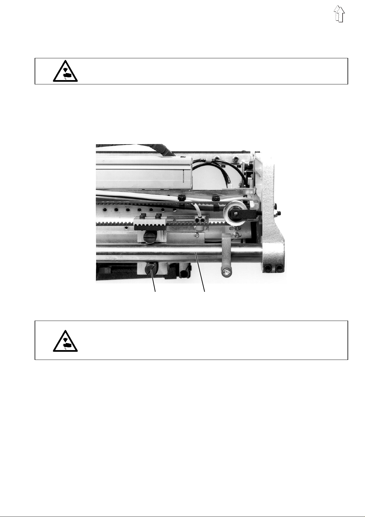
2. T ransport Carriage
2.1 Rollers
The advance of the transport carriage occurs via a step motor.
Caution Risk of Injury !
Do not reach into the area of moving machine parts.
The transport carriage is guided on the extension pipes 2 by ball
sleeves on the left and by rollers on the right.
The rollers 1 are set tight at the factory.
12
Caution Risk of Injury !
Turn the main switch off.
Set the play o f the rollers 1 o nl y with the main s wi t c h t ur n ed off.
To remove play:
–
Remove the c o ver p l at e a ft er l o os e ning the mounting s c re w s.
–
Loosen
one
of the eccentrically bearinged rollers 1 and set tight.
5
Page 6
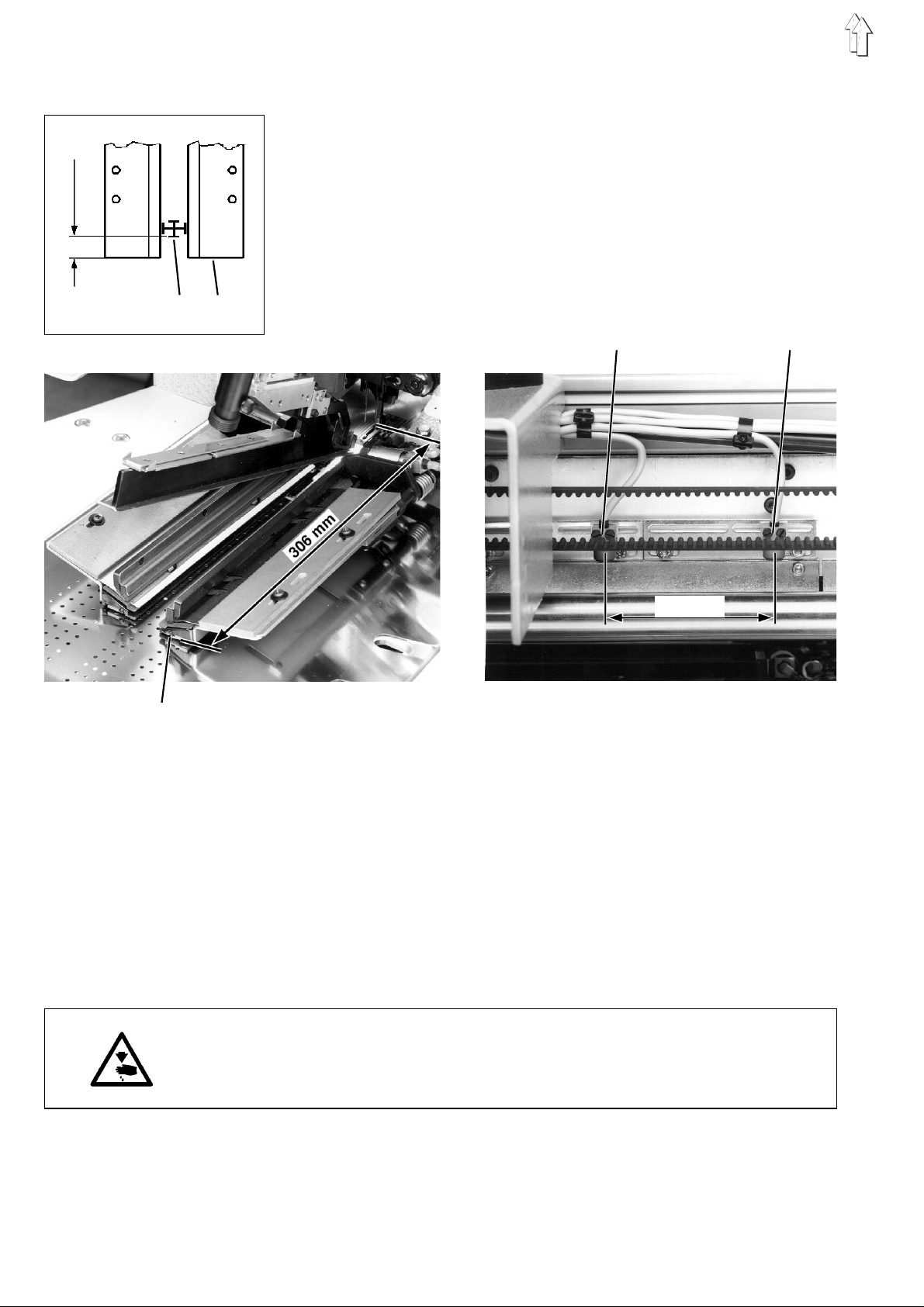
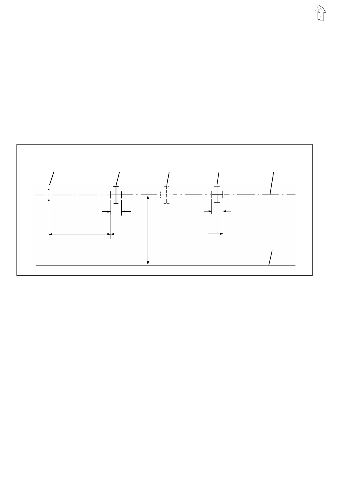
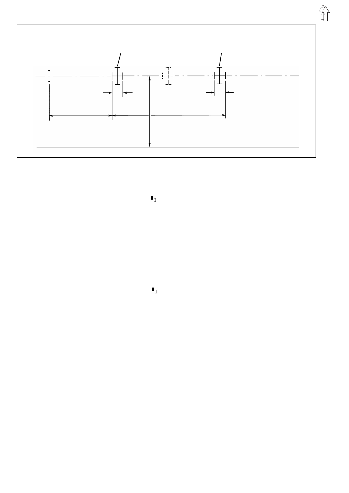
2.2 Forward End Position
15 mm
1 2
switch b2
The
carriage.
In this posi ti o n t he c l ea ran c e f r om th e f or w ar d ed ge s of th e
forward-lyi n g n ee dl e s to th e f or w ar d ed ge s 2 o f t he tr a nsport clamps
must be 306 mm.
This corresp on ds t o a c l ea r an ce o f 1 5 m m f rom the forward ed ge s 2 o f
the transport clamps to the H-light marker 1 (see sketch).
switch b3
The
It prevents a possible striking of the transport carriage on the machine
head.
The clearance between the switches b3 and b2 must be 90 mm.
determines the forward end position of the transport
serves as a safety switch.
b3 b2
90 mm
2
Checking the switch setting
–
Turn the main switch on.
–
Step back on the left pedal.
The transpo rt c a r ri ag e r u ns i n to i ts r e ar e nd position.
–
Step forward on th e l e ft pedal.
The transpo rt c a r ri ag e r u ns i n to i ts f or w ar d en d p os i t i on .
It runs over the switch b2 (reference po s i ti o n) a l on g i t s pa th .
After a furt he r run of approx. 80 mm it stops in the f orward end
position.
–
Check the clearance of 306 mm from the forward edge of the
forward-lying needles to the forward edges 2 of the transport
clamps.
Correcting the switch setting
Caution Risk of Injury !
Turn the main switch off.
Correct the pos it i on of th e s w i tch es b2 and
switch turned off.
b3
only with the main
–
Remove the cover plate after loosening the mounting screws.
–
Set the switches b2 and b3 after loosen i ng th e c l a mp i ng sc r ew s .
–
Tighten the clamping screws again.
6
Page 7
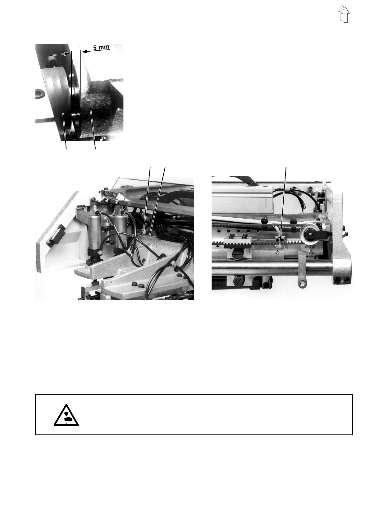
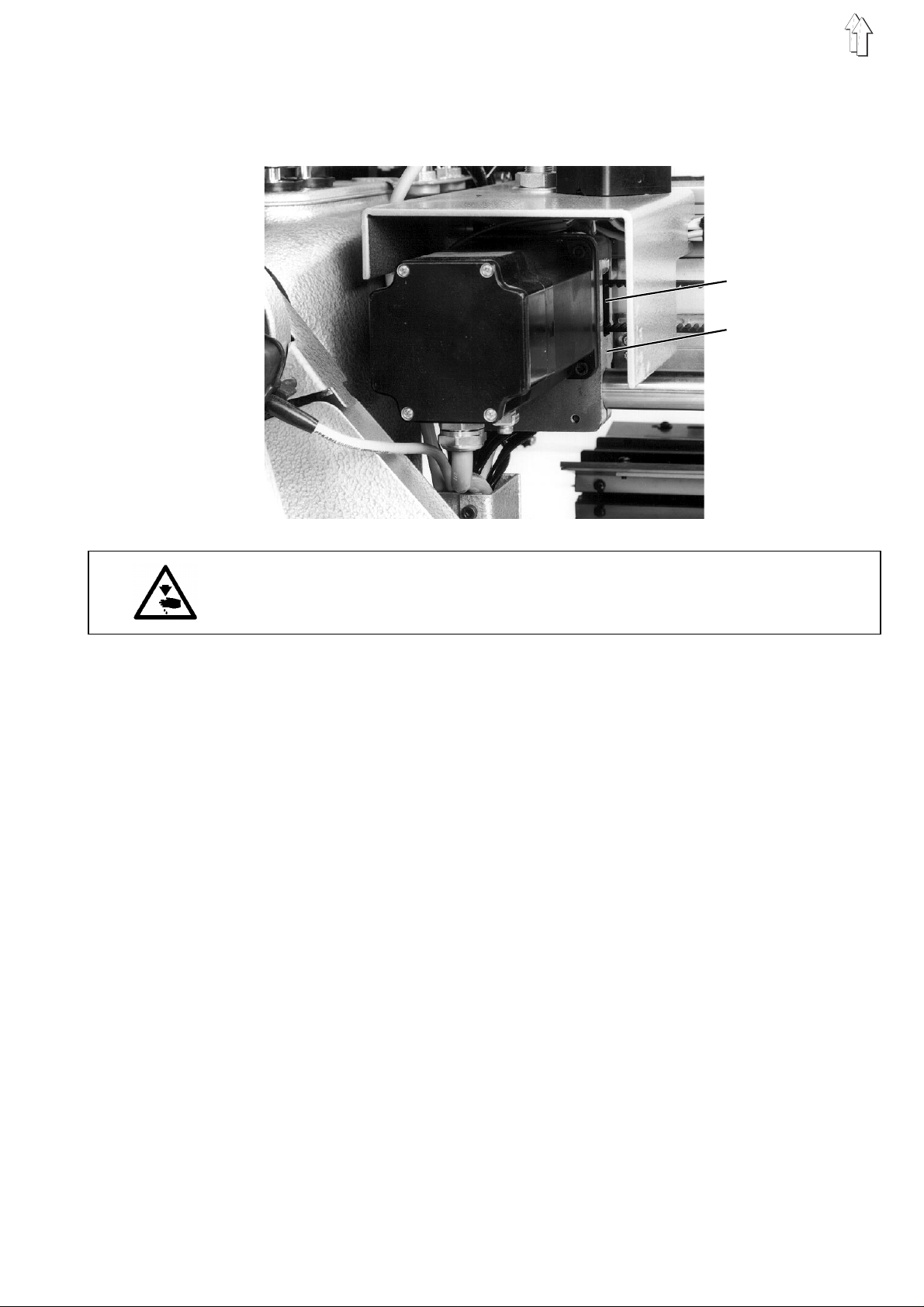
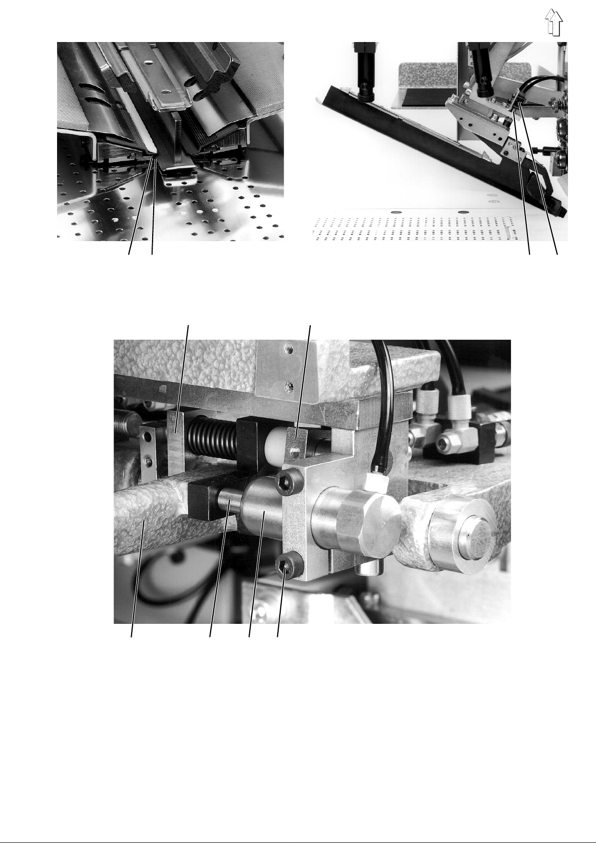
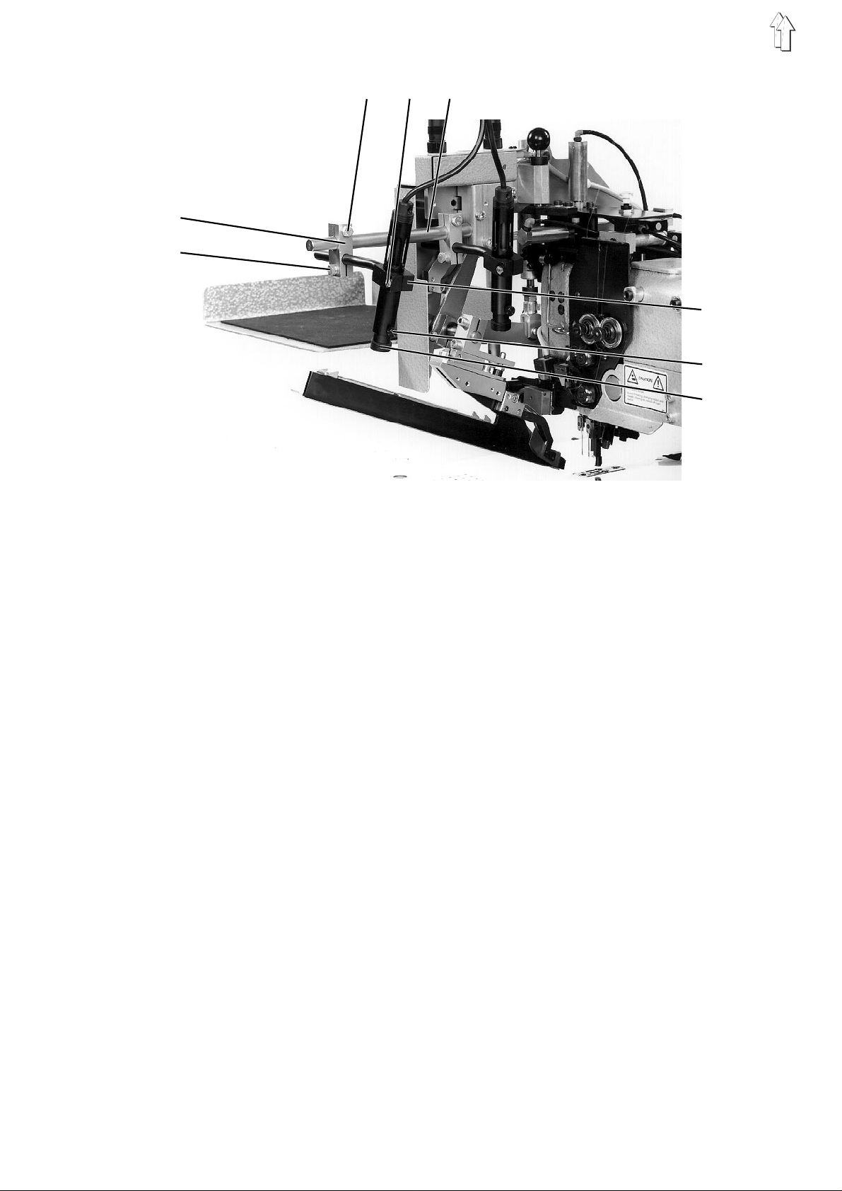
2.3 Rear End Position
switch b1
The
carriage.
Set switch b1 so that in the rear end position there is still a clearance
of 5 mm between the damper discs 1 and the transport carriage 2.
The surface 4 on the transport carriage must open the pneumatic
valve 3 when running into the rear end position.
With the main switch turned off and pneumatic valve 3 opened the
interlock of the cover hood and the cloth slider plate is released.
determines t he r ea r en d p os i t i on of the transport
1 2
34
Check the positions of the switch and the pneumatic valve
–
Turn the main switch on.
–
Step back on th e l e ft pedal.
The transport carriage runs into its rear end position.
–
Check the clearance dimension of 5 mm between the damper discs
1 and the tran spo r t c a rr i ag e 2 .
–
Check if the pneumatic va lv e 3 i s op en ed by t he s urface 2 on the
transport carriage.
b1
Correcting the positions of the switch and the pneumatic valve
Caution Risk of Injury !
Turn the main switch off.
Set the posit i on s of th e s w i tc h b1 and the pneumatic valve 3 only with
the main switch turned off.
–
Slide switch b1 after loosening the clamping screws.
–
Set pneumatic valve 3 so that it is opened by the surface 4 on the
transport carriage.
–
Tighten the clamp ing screws again .
–
Attach the cover plate.
7
Page 8
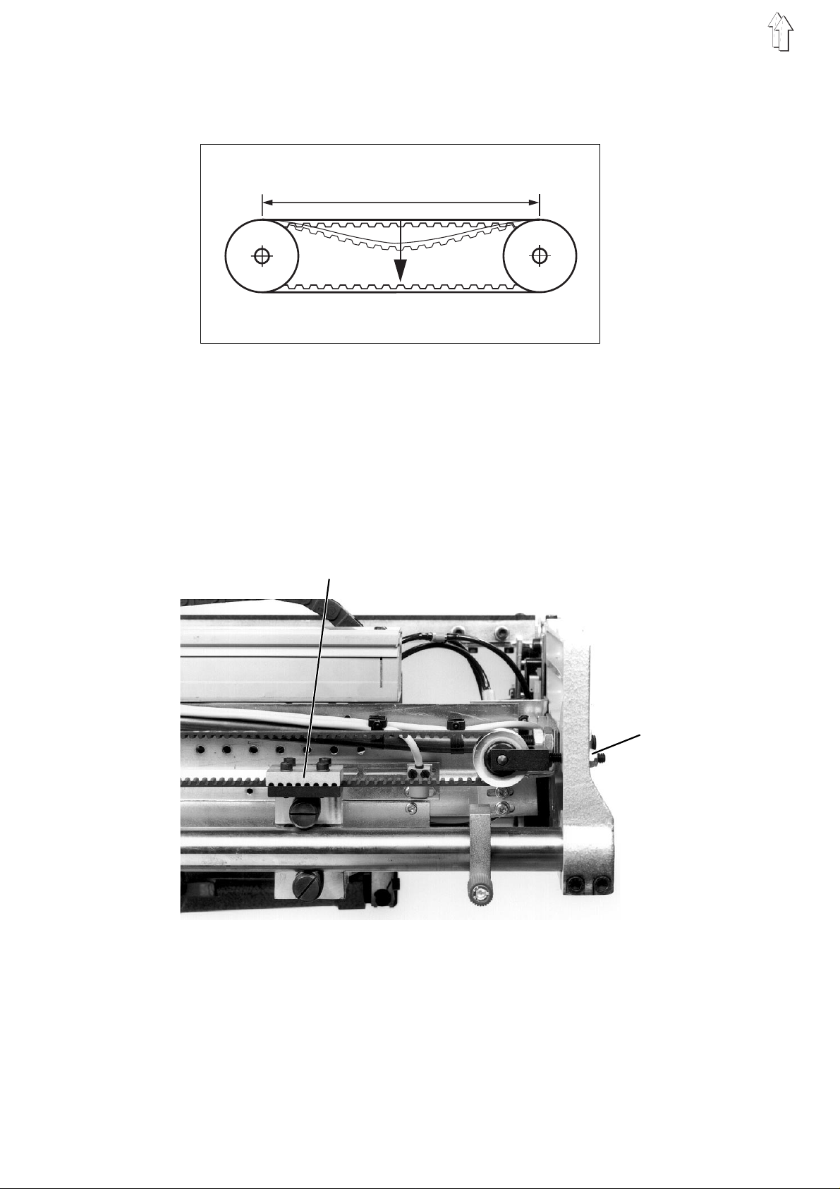
2.4 Timing Belt Te nsion
At the middle of the belt section S the timing belt must bend in 13 mm
under the test l oa d F V = 500g.
S
{
Consequences of too high timing belt tension:
–
Reduced life
–
Running noises
Consequences of too low timing belt tension:
–
No flawless tooth interlocking between the belt teeth and the pulley
teeth
–
Jumping of the teeth under load
1
2
–
Attach the tes t loa d i n th e m i dd le t he ti m i ng be lt (e .g . with the aid
of a spring scale).
The timing belt is correctly tensioned when the upper half of the
belt just touches the lower half of the belt.
To correct:
–
Correct the ti mi n g bel t te ns i o n a t n ut 2.
The nut 2 is e qu i pp ed wi t h a s el f -l oc k i n g t hre ad.
8
Page 9
2.5 Changing the Timing Belt
To simplify changing, the timing belt is split.
It is held together by the timing belt clamp 1.
3
4
Caution Risk of Injury !
Turn the main switch off.
Change the timi n g b el t on ly wi t h t he ma in s w i tc h tu rne d o ff.
Remove the old timing belt
–
Loosen the four clamping screws on the timing belt clamp 1.
–
After loos en i ng th e t i mi n g b el t c lamp 1 pull the ti mi n g b el t ou t o f
the housing 4.
Inserting the new timing belt
–
Push one end of the timing be l t t hr o ug h t he op ening 3 on the
timing belt p ul l e y of th e s t ep mo to r.
–
Carefully turn the timing belt pulley for placement of the timing belt
with a suitable tool.
The timing be l t p ul l e y i s ac cessable throug h t he opening 3.
–
To connect the two timing belt ends slacken the timing belt tension
a little at nu t 2.
–
Join the tw o t i mi n g b el t en ds w i th th e t i mi n g b el t c lamp 1.
–
Set the timi ng be lt tension (see Chap te r 2. 4).
9
Page 10
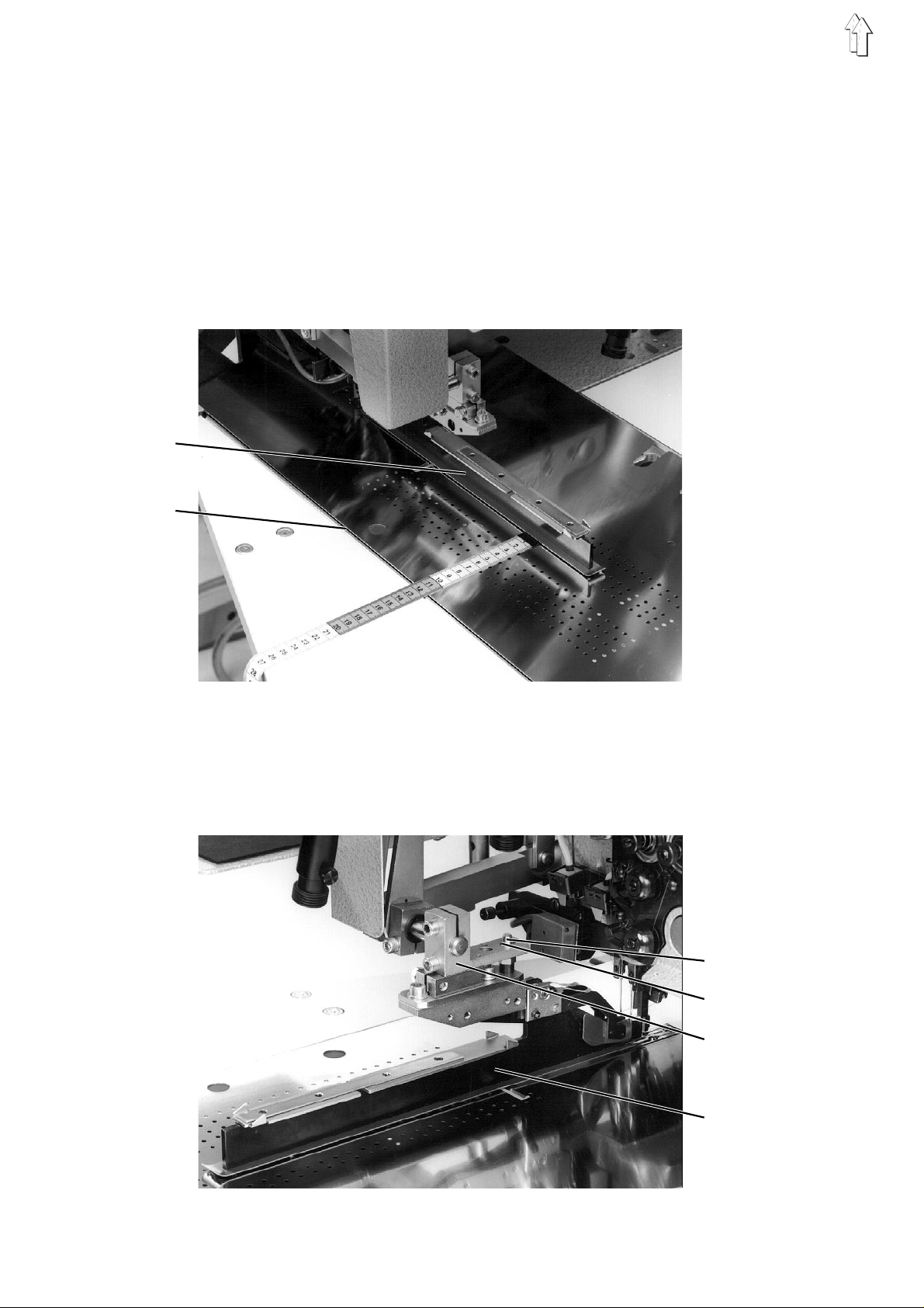
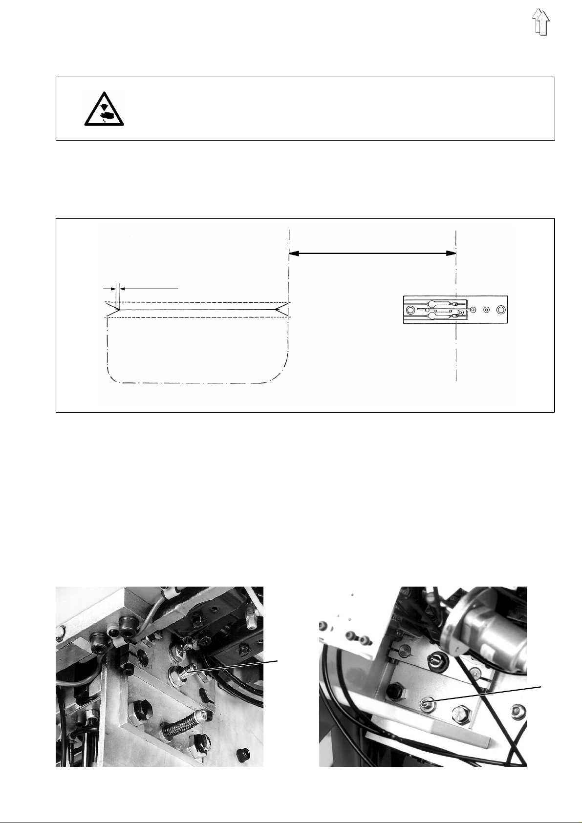
3. Folder
For the unimpaired transport of the material and a flawless fabrication
of the pocket o pening, the fold i ng an d c u tt i ng to ol s , as w el l a s th e
marker light s , m us t be al i g ne d t o t he c en te r of th e p oc k e t o pe ni n g.
The incision of the center knife is seen as the center of the pocket
opening.
The measurem en t l in e 2 was traced on th e machine plate at th e
factory.
It runs parall e l to th e c e nt er o f t he po c k et op en i ng , t hat is, to the
center knif e i n ci s i on at a c l e ara nc e of 12 5 m m.
By proper mounting of the fol de r 1 i t c an be al igned from the
measurement l i n e t o t he c en te r of th e p oc k e t o pe ni n g
(see Chapter 3. 2) .
1
2
Proper mounting of the folder:
–
The folder 1 is p us h ed up on to the clamping piece 5 until it to uch es .
–
The pin 3 catc h es i n s l ot 4.
3
4
5
1
10
Page 11
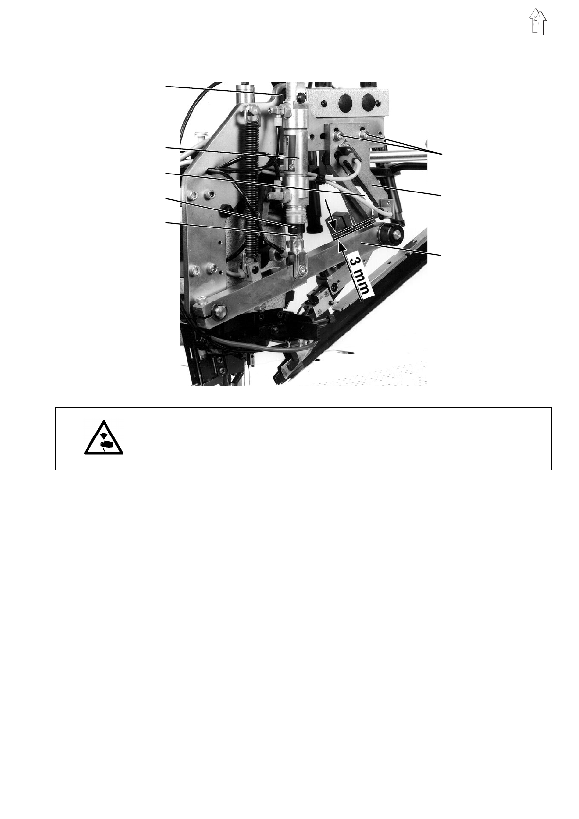
3.1 Stroke Movement of the Folder
6
10
7
11
8
9
12
13
Caution Risk of Injury !
Turn the main switch off.
Set the stroke movement of the folder only with the main switch turned
off.
With the folder raised:
There must be a safety clearance of 3 mm between the lever 13 and
the bottom of the curve piece 12.
–
Loosen nut 6.
–
Set the mounting of the cylinder 7 higher or lower accordingly.
–
Tighten nut 6.
With the folder lowered:
The clearance between the folder sole and the cloth slider plate must
be 2 mm along the wh ol e l engt h.
–
Loosen nut 10.
–
Set the clearance between the bottom of folder sole and the cloth
slider plate by turning the piston rod of the cylinder 7.
–
If the roller lays on in the lowest point of the curve path 8:
Loosen screws 11.
Set the curv e p i ece 12 lower.
11
Page 12
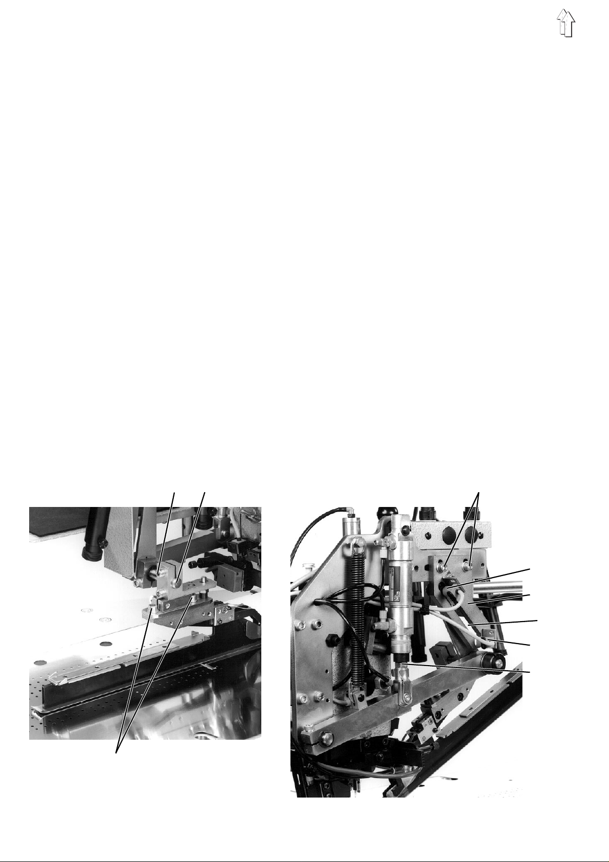
–
Loosen clamp i ng s cr ew 14 .
–
Turn the folder slig htly on the axle 15.
There must b e a un i fo rm c l e ar a nce between the fo l de r s ol e an d t he
cloth slider plate along the whole length.
–
Tighten clamping s c rew 14 and nut 10.
–
In the lowest p osi t i on of th e f ol d er s e t t he cur ve pi e c e 1 2 a s
follows:
There must b e a c l ea rance of 0.5 mm between the rolle r and the
lowest point of the curve path 8.
–
Tighten screws 11.
Proximity switches b4 and b5
The proximity switches b4 and b5 monitor the t w o en d p os itions of the
folder.
Switch b4: Monitoring of the upper folder position
switch b5: Monitoring of th e l o we r fol de r po s iti o n
The checking of the correct switch settings occurs in program
–
–
–
–
–
–
–
14 15
P63
Turn the main switch on.
Set the "
Press the "
The program i s ac t i vated.
Set the "
The display shows the switching status "-" or "+".
Loosen the mounting screws on the switch b4 or b5 slightly.
Align switch b4 and b5 to the roller i n th e c o r res p on di n g f ol d er
positions. The display must show the switching status "+".
Tighten the mounting screws of the switch again.
Program
STOP
Program
" switch to "63".
" key
" switch to "4" (switch b4) or "5" (switch b5).
11
:
b4
12
12
8
b5
10
16
Page 13
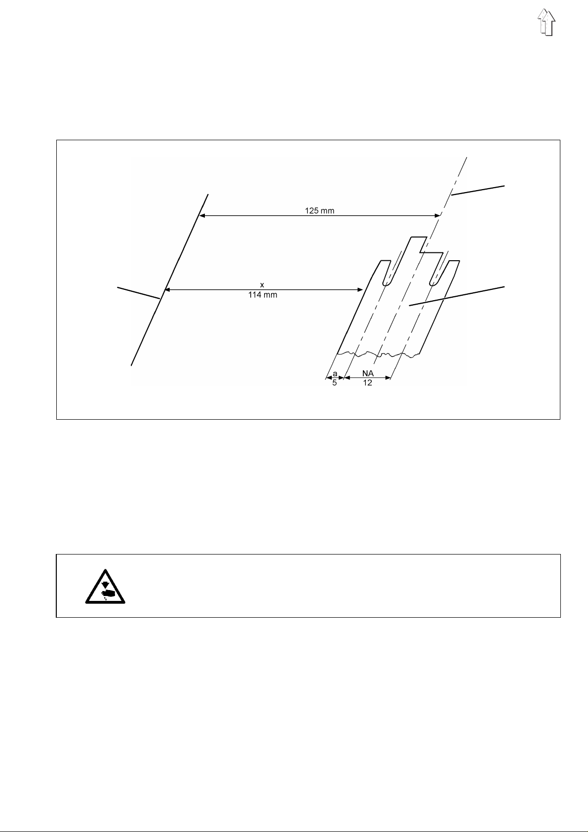
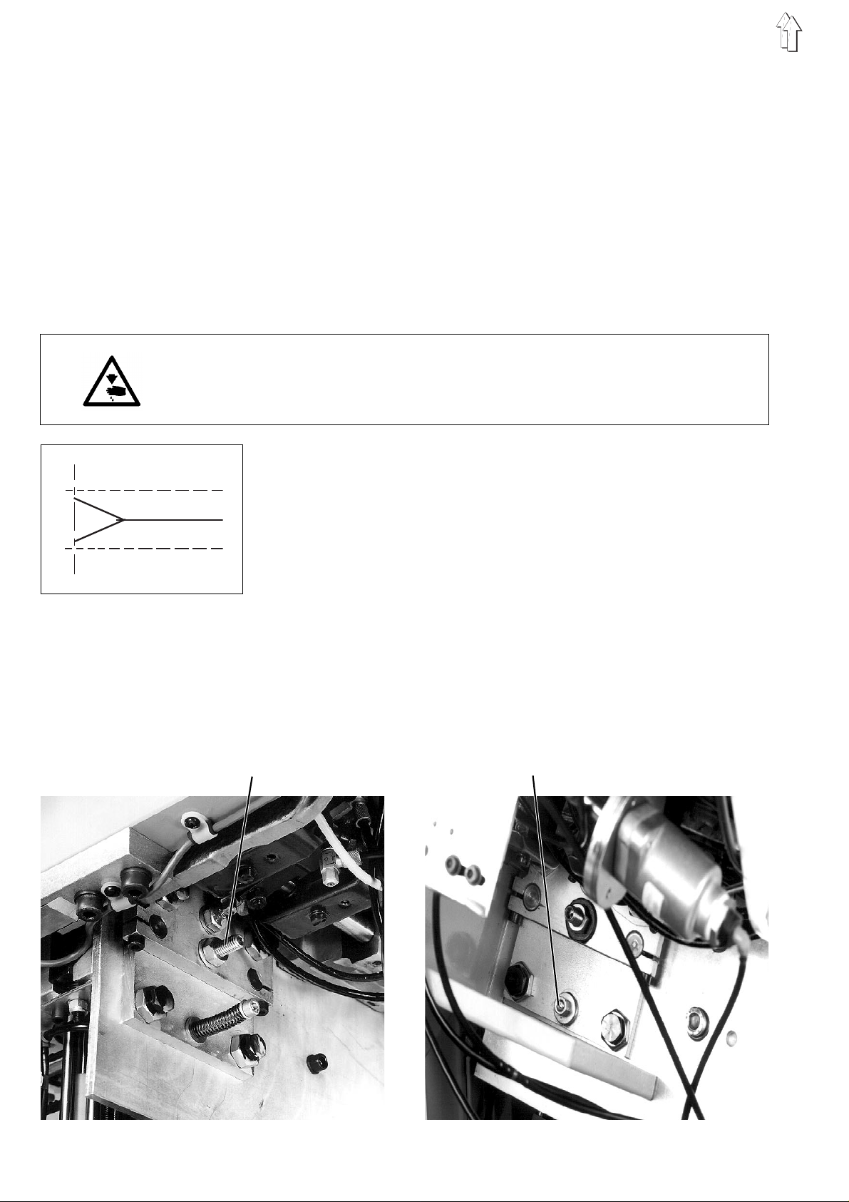
3.2 Aligning the Folder to the Center of the Pocket Openi ng
When properly mounted the folder can be aligned from the
measurement line 17 to the center of the pocket opening.
Dependent on the width of the folder sole 19 the dimension x can be
establishe d. W i th th e a i d o f t hi s d i me ns io n the folder can be ali g ne d to
the center of t he pocket openi ng 18 an d p ar a l lel t o the measuremen t
line 17.
18
17
19
–
Subtract th e p i pi n g w i dt h a and half of the
needle clearance NA from the dimension 125 mm.
Example f rom the sketch : 12 5 mm - a - 1/2 x NA x
125 mm - 5 mm - 1/ 2 x 1 2 m m = 114 mm
Piping widt hs a nd ne edle clearance s fo r ot her folders can be fo un d
in the Operating Instructions.
Caution Risk of Injury !
Turn the main switch off.
Align the folder to the center of the pocket opening only with the main
switch turned off.
–
Loosen screws 16 slightly.
–
Align the folder sole parallel to the measurement line 17 with the
aid of a measur i n g s t i ck .
–
Tighten screws 16.
–
Loosen clamping screw 14 slightly.
–
Set the clearance x (in the examp l e x = 114 mm) betwee n
measurement l i n e 1 7 a nd th e l e ft ed ge of the folder so le 19.
For this slide the folder sideways.
–
Tighten clamping screw 14.
13
Page 14
3.3 Position of the Folder to the Needles and the Center Knife
With a properly mounted folder the following positions must be
attained:
–
In the most forward position the needles must enter the needle
holes of the folder sole unhindered (without being deflected).
–
When the center knife 1 enters the knife guard 2 in the most
forward position there must still be a clearance of 0.5 to 1 mm
between the front edge of the knife and knife guard.
0,5 - 1 mm
1
2
3
Caution Risk of Injury !
Turn the main switch off.
Align the fol d er t o t he ne ed l es a nd th e c e nt er k n if e on l y wi t h t he main
switch turned off.
To correct:
–
Loosen screws 3 slightly.
–
Slide the fol d er i n th e d i rec t i on of tr a ns p ort .
–
Tighten screws 3 ag ai n .
14
Page 15
3.4 Guide Plates on the Folder
With the needle bar link in the most forward position the edges 2 of the
guide plate s mu s t e x te nd ap pr o x . 1 mm to th e r e ar b ey o nd th e n ee dl e s .
The leaf springs 1 hold the guide plates down on the folder sole with a
slight pressure.
The pressure must so dimensioned that the sprung guide plates can
be easily raised by the piping strip running in or by the flap.
1
2
1 mm
Caution Risk of Injury !
Turn the main switch off.
Correct the pressure of the leaf springs only with the main switch
turned off.
To correct:
–
Set the pres s ure by a dj u s ti n g t he l ea f s p r ing s 1.
15
Page 16

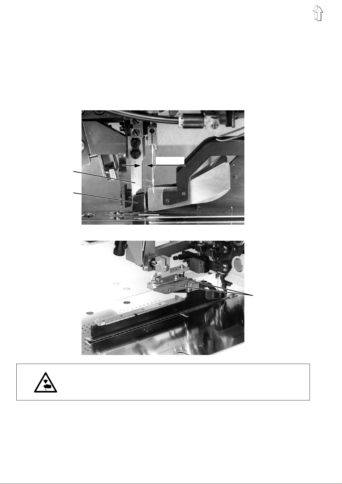
4. Clearance of the T ransport Clamps to the Folder Sole
There must be a certain cleara nc e be tw ee n t he outer edges 2 of t he
folder sole and the inner edges 1 of the transport clamps. By medium
weight cloth for ready-made clothes it must be e.g. 1 to 1.5 mm.
The clearance is necessary in order to assure uniform piping widths on
both sides an d a n u nh i nd er e d t r an sport of the mater i al.
4.1 Manual Adjustment of the Transport Clamps (745-22)
With the
the Allen screws 6.
With the
The scale plates 8 serve as setting aids.
–
–
–
ATTENTION !
The markings on the scale plates 8 are matched to the needle
clearance of the machine head.
When attaching need le holders for other needle clearances the scale
plates 8 must al s o be r ep lac e d.
745-22
745-23
To set th e c lea r an c e tu rn the Allen screw 6. To turn use the socket
wrench 5 to be found in the acc ess o r i es p ac k .
The scale plates 8 were aligned at the factory as follows:
When the poi n te r 7 p oi n ts t o t he marking "I" the correct clearance
for sewing medium weight material of two-sided piped pocket
openings is set.
The second marking gives the clearance for sewing a greater
piping width or a one-sided piped pocket opening.
By stepping fo r wa r d o r ba c k on th e l e ft pe da l c on du c t t es t run s
with the tr an spo r t c a rr i ag e.
The transport clamps must pass the guide plates 4 and the thread
catcher 3 unhindered.
745-24
and
only the rig ht tr a ns p ort clamp is set m an ually.
both transpor t c l am ps a re s e t by turning
Pneumatic qu i ck cl amp adjustment
By frequent changes of the folder between single and dual piping the
pneumatic qui c k cl a mp ad j us t me nt s i mp l i fi e s the setting of th e
transport cl am ps .
With the
clamp adjustment as standard equipment (Description see
Chapter 4.2).
With the
(Order no. 792 00 5981).
745-23
745-22
the left trans p or t c lam p has the pneumati c q ui ck
745-24
and
it is available as option al e qu i pm en t
16
Page 17
12
5
34
6
7
8
17
Page 18

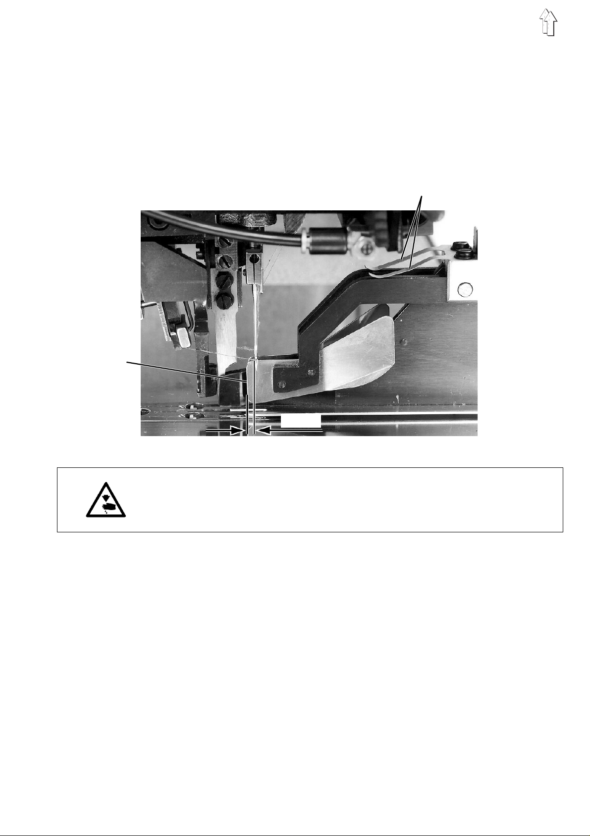
4.2 Pneumati c Quick C lamp Ad justm ent (7 45-23)
With the
clamp adjustment as standard equipment.
When changing the the folder between single and dual piping the left
transport clamp correctly sets itself automatically.
The clearance between the outer edges 2 of the folder sole and the
inner edges 1 of the lowered transport clamps is dertermined as
follows:
–
–
Caution Risk of Injury !
Turn the main switch off.
Set the quick c l a mp ad j us t me nt on l y wi t h t he ma i n switch turned off.
Folder for dual piping
Presetting :
The clearance between clamp arm 7 and clamping piece 5 must be
approx. 3 mm wi t h t he pi s t on r od 8 f ul l y e x te nd ed .
–
–
745-23
For dual piping by the position of the cylinder 9 with air.
For single piping by the position of the stop 6.
Insert the fol d er f or dual piping.
The extended pi n 3 o pe r at es t he v al ve 4 for the quick c l am p
adjustment.
The correct c learance of the tra ns p or t c l am ps to the folder s ole i s
automatically set.
Slide the tr an s po rt c a r ri ag e m an ua l l y un ti l t he tra ns p or t c l am ps l i e
at the level of the folder sole.
the left trans p or t c l am p h as t he pneumatic qui ck
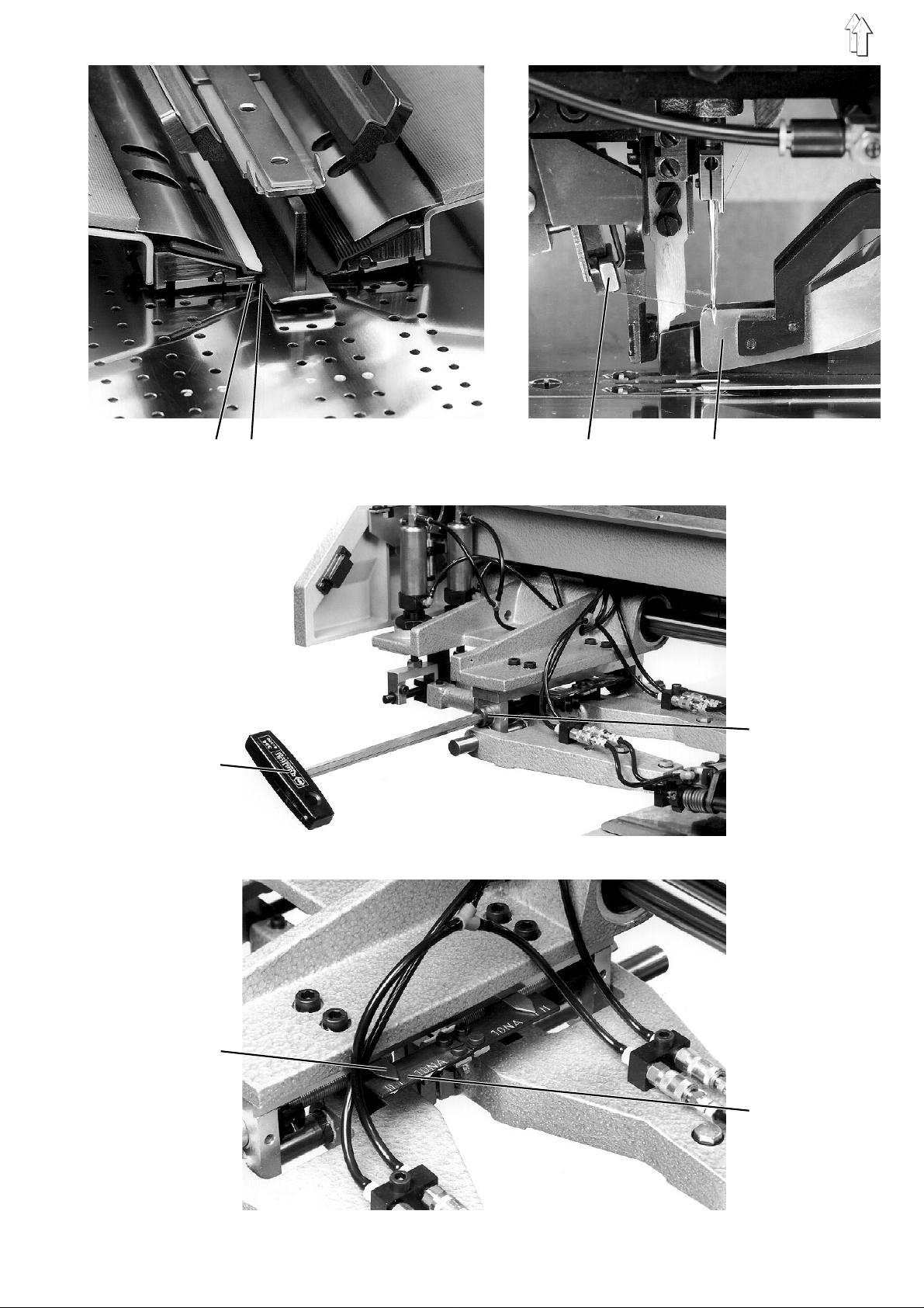
–
Loosen clamp i ng s cr ew 10 .
–
Set the clearance between the folder sole and the inner edges of
the lowere d t ran s po r t cl a mp s by s li d i ng th e c y l inder 9.
–
Tighten clamping s c rew 10.
Folder for single piping
–
Insert the fol d er f or s i n gl e pi p i ng .
–
With the quick clamp adjustment vented and touching the stop 6
check the clearance dimension of 1 to 1.5 mm between the
transport clamps 1 and the folder sole 2.
To correct:
–
Loosen the clamping screws on the stop 6.
–
Slide the st op 6 i n th e a pp r op r iate direction.
–
Tighten the clamping screws again.
18
Page 19
12
3 4
5 6
7 8 9 10
19
Page 20
5. Marker Lights
1 2 3 45
The light markers 2 and 4 limit the sewing area.
Alternatively a 3rd marker light, available on request, can be attached
(Order no. 793 02 20 68 ) .
The multiple masks built into the lamp optics make possible the
following application:
–
Because of th e s m al l H - li gh t markers a clear a nc e of 10 mm
between che s t d art and flap edge c an be ac h i ev e d i n th e
positioni ng of j ac k e t f ron ts .
By setting the marker lights higher the clearance can be increased
to a maximum of 15 mm.
–
Turn the marker light 90°.
Clearances f r om 15 mm to a m ax i m um of 25 mm c an be s et by
setting the l a rge H-l i g ht ma rk er h i gh er o r l ow er.
10
111
1
: Needles
2
: Light mark er -f or w ar d po s i tio ni n g p oi n t
3
: 3rd marker l i g ht ( on req ue s t)
After setting the marker lights higher or turning them it is essential that
the following points be observed:
–
Reset the lamp ho l der.
–
Align the li g ht ma r ker s congruent to the c e nt er o f t he po c k et
opening.
–
Keep to the maximum sewing area.
10
180
125
6
4
: Light marker-rear positioning point
5
: Center of the po c ket op en i ng
6
: Measuremen t l i n e
20
Focusing the light markers sharp
–
Loosen clamp i ng s cr ew 13 s l i gh tl y.
–
Focus the lig ht marker sharp by s e tt i ng th e t ub e 1 4 higher or lower.
–
Tighten clamping s c rew 13.
Page 21
10
11
7 8 9
12
13
14
Aligning the light markers
All light markers must be aligned to the cutting line (center of the
pocket openi ng 5) .
The clearance between the lengthwise lines of the H-light markers and
the measurement line 6 must be 125 mm.
–
Loosen the clamping screws 8 of the lamp holder 12 slightly.
–
Set the lam ps h i gh er o r lower in the lamp ho l de rs 12 .
There must be a cl e ar a nc e of 10 mm be tween the crosswise lines
of the small H-light marke r ( s ee sk et c h) .
–
Turn the lamps in the lamp holders 12.
The crosswise line of the H-light marker must lie parallel to the
measurement l i n e 6 .
–
Tighten clamping screws 8.
–
Loosen the cl a mp i ng s c rews 11 on the hold er block 10 slig ht l y.
–
Set the clearance of the light markers to the measurement line 6
by pushing in or pulling out the lamp holder 12.
–
Tighten clamping screws 11.
–
Loosen clamping screws 7 slightly.
–
Slide the ho l de r bl o c k 10 on the support axle 9.
The clearances to be set between the light marker and the
forward-lyi n g n ee dl e s are to be found in the s k e tc h .
–
Tighten clamping screws 7.
21
Page 22
2 4
111
10
180
125
Check the exact position of the light markers
Light marker 2 (seam beginni ng ) :
–
Set the " " key on the front panel of the control unit to
"Positioning point-forward".
The LED above the key is lit.
–
Designate the desired seam beginning with a chalk mark on the
sewing piece.
–
Position the s e wi n g p iec e wi t h t he cha l k ma rk on th e f orw ar d
crosswise line of light marker 2.
–
Start the sew i ng pr o c ed ure .
The seam must begin on the chalk mark.
–
To corr ec t : R ea l i gn ma r ker l ight 2 after loos e ni n g i t s holder.
10
Light marker 4 (seam end):
–
Set the " " key on the front panel of the control unit to
"Positioning point-rear".
The LED above the key is off.
–
Make an analog ous check of the a l i gn me nt of the light mar ker 4 fo r
the seam end.
22
Page 23
6. Knife Brackets for the Cutting of the Corners
Caution Risk of Injury !
Do not reach into the area of the corner knives.
The rapidly rising corner knives can cause serious cuts.
Presetting:
The clearance between the cutting edges of the corner knives in the
knife bracke t " s e am en d" a nd th e f or w ar d - ly i ng ne ed l es m us t be
130 mm
(745-22;-23)
or 135 mm
(745-24)
(see sketch).
ca. 1-2 mm
130 mm (
135 mm (
The measuring and setting is to be made at the w i de s t p oi n t o f t he
corner knife with the knife bar raised.
–
Tilt the machine he ad to the back.
–
Set the clea r an c e d i me nsi o n o f 1 30 mm by t urn i ng th e s t op
screw 1 (
2 are in the ar ea un de r th e h oo k s.
–
The knife incisions must end at the seam beginning before the first
and at the seam end before the last stitch (see sketch).
This corresp on ds t o t he front edge of th e f l ap an d the rear edge of
the flap with the flap sewn on.
745-22 and 745-24
745-22;-23
745-24
) or 2 (
)
745-23
)
). The stop screws 1 and
745-22, 745-24: 745-23:
1
2
23
Page 24
6.1 Adjusting the Position of the Corner Incisions
–
Call up the lo ng est s ew i ng di st an c e (e .g . 1 50 mm ) with the L1 key
on the front pa ne l of th e c o nt rol u ni t .
–
Conduct a trial s e am .
It is useful to first iron a piece of nonwoven fleece onto the sewing
piece. This shows the corner incisions well.
–
Check the seam and cut patterns.
–
To correct: Make the following settings.
Presetting:
–
Set the corr ect i on v al u es f or s e am be gi n ni n g ( N A ) an d seam end
(NE) to the m ed i an v al u e 5 0 (n o c o r rec t i on )
(see Short De sc r ipt i on Mu l tic o nt r ol) .
Caution Risk of Injury !
Turn the main switch off.
Adjust the position of the corner incisions only with the main switch
turned off.
Adjusting the corner incision of the knife bracket "seam
beginning"
The knife bracket "seam beginning" must cut up to
stitch (see sketch).
–
745-22;-24:
745-23:
–
Set the position of the corner incision at the seam beginning by
sliding the knife bracket 2.
–
Tighten clamping l ev e r 3 or screw 5 agai n.
Loosen the clamping lever 3.
Loosen screw 5 .
in front of
the first
745-22; -24:
Adjusting the corner incision of the knife bracket "seam end"
The knife bracket "seam end" must cut up to
–
If necessary, correct the corner incisions of the knife bracket
"seam end" a t s t op s c rew 1 (
745-22; -24
1
745-23:
2
in front of
) or 2 (
745-23
the last stitch.
).
24
Page 25

745-22: 745-23:
745-24:
3 4
5 4
3 4
25
Page 26

Adjusting the scale
With the
corresponding to the sewing distance (in the example 150 mm) must
lie congrue nt to th e e dg e 6 of the knife brack et 2
–
–
745-22
Loosen screw 9 slightly.
Set the scale 7 with the dimension 150 mm (see Example)
congruent to th e e dge 6 of the knife br a c ket 2.
and
745-23
the scale 7 with the dimension
("seam beginning")
.
With the
sewing dist an c e ( in the example 150 m m) m ust lie congruent to the
edge 15 of the k n i fe bra c k et 11
–
–
Thus the scale is also correctly set for the changeover to the sewing
distances L 2 a nd L3 ( see O pe r at i ng In s tru c ti o ns ).
Aligning the corner incisions to the seams
The corner incisions must lie symmetric to the seams (illustration a).
The clearance of the incision ends to the seams must be equal on both
sides (illustration b).
745-24
Loosen screw 10 slightly.
Set the scal e 1 4 w i th th e dimension 150 mm (s ee E x am pl e )
congruent to the edge 15 of the knife bracket 11.
a) b)
the scale 14 w i th th e d i me ns i o n c o rr es p on di n g t o t he
("seam end" )
.
–
Loosen screw 8.
–
Turn rod accordingly.
Set a clearance of approx. 5 mm between the block 1 and the knife
bracket 2 with the cylinder run in on both subclasses. The safety
clearance prevents a striking of the piston rod in the cylinder.
–
Tighten screw 8.
–
Set the same cl ea r an c e b et we en i nc i si o n e nd and seam on both
sides.
745-22
745-23
745-24
Setting the stroke speed of the corner knives
–
Regulate the stroke speed at the one-way restrictor valves 5
(745-22; -23)
The rising m ov e me nt s ho ul d be r ap i d, bu t n ot j erk y.
: Turn stop nut 4.
: Turn the eccentric 9.
: Turn stop nut 12.
(745-24)
or 13
.
26
Page 27

745-22: 745-23:
1 2 3
5 mm
7 9
745-24:
4 5 6 7 8 9
10 11
2 6 5 7 9
12 13 14 1 5
27
Page 28

6.2 Adjusting the Knife Brac kets for Bias Corne r Incisions (745 -24)
Caution Risk of Injury !
Turn the main switch off.
Adjust the knife brackets for bias corner incisions only with the main
switch turned off.
Do not reach into the area of the corner knives.
The rapidly rising corner knives can cause serious injuries through
cuts.
Aligning the scale plate 9
–
Turn star knobs 7.
The height of the stopper pla te s 5 must be set so t ha t t he s c rews 4
lie at the ce nt er o f t he s l ot s 3.
–
Loosen screws 8.
–
Set the heig ht of th e s c a le plate 9.
The wide mar k er l i n e 1 0 i n th e m i dd l e o f t he s c al e mu s t li e at one
level with th e l o we r ed ge s 6 o f t he s to pp er p l at es 5 .
–
Tighten screws 8.
Setting the awl rod and knife rods
The setting i s m ad e w i th ga ug e 11:
ATTENTION !
Only at the
–
Remove block 18 including stop screw 1.
Loosen screws 17 for this.
–
Loosen screws 27.
–
Remove clamping pieces 16 and corner knife 26.
–
Loosen screws 14.
–
Remove the awl rod 25 .
–
Loosen clamping screws 23, 32 and 33.
–
Insert gauge 11 into the groove of the awl r od 13 .
–
Tighten screws 14.
–
Turn the forks 22 on the knife rods 21.
The knife rods should be guided tight but still be easily movable.
Unhook the tension springs 24 and 34 to check.
–
Set the knife rods 21.
The upper edges of the knife holders 12 and the gauge 11 must be
at the same level.
–
Set the awl ro d 13.
When the clamping piece 31 is at its lower rest, the gauge 11 must
touch on position plate 15.
–
Tighten screw 32.
–
Align the knife holders 12.
The knife ho l de rs 12 mu s t l a y pa ral l e l on to th e o uter edges of the
gauge 11.
"seam beginning"
knife bracket.
28
Page 29

1 2
–
Turn the awl rod 13 and knife rods 21 ac c o rdi n gl y.
–
Tighten the clamping screws 23 and 33 again.
–
Check the ease of movement of the knife rods 21 and the awl
rod 13.
–
Attach the block 18 at the
It is then ess e nt i al t o s e t t he ba s e p os ition of the posi t i on pl a te 28 .
Setting the base position of the position plate 28 of the "seam
beginning" knife bracket
The base posi t i on of th e p os i t i on plate 28 is set at th e f ac t or y.
It must only b e r e s et af te r th e re mo v al o f t he bl o c k 18 (e.g. for settin g
the awl rods a nd k ni f e r o ds) .
–
Loosen lock nut 2.
–
Turn back the stop screw 1 slightly.
–
Turn the setting sc rew on star knob 20 un ti l its surface 19 l i es
centered in block 18.
–
Set the base position of the position plate 28 with the stop screw 1.
In the base position the marker lines on the knife bracket 29 and
on the positi on pl a te 28 must lie prec i s ely a bo v e o ne an ot her.
–
Tighten lock nut 2.
"seam beginning"
knife bracket again.
3
4
5
6
7
11
10
8
9
8
12
13
16
17
18
19
20
21
22
23
25
26
27
28
29
30
31
32
33
14
15
24
34
29
Page 30

6.3 Changing the Corner Knives (745-22 and 745-23)
Blunt corner knives are to be replaced with the knife set in the
accessories pack.
Please find th e o r de r numbers for the c or n er k n i fe s et s i n C ha pt er 1 of
these Service Instructions.
Caution Risk of Injury !
Turn the main switch off.
Change the cor ner k niv e s on l y wi t h t he ma in s w i tch tu r ne d o ff.
Danger of cuts!
Do not reach i nt o t he s ha r p b l ad es of the corner kn i v es.
1
2
3
45
–
Screw out screw 4.
–
Pull the knife holder 5, complete with the corner knives 2 and the
awl 1, off of the knife bar.
–
For safe working, clamp the knife holder 5 in a vise.
–
Loosen clamp i ng s cr ew 3.
The clamping collar in the knife holder 5 is released.
–
Remove awl 1 and both corner knives 2.
–
Insert new corner knives in the slits of the knife holder 5.
Attention!
The angle-g rou nd bl a de s mu s t s h ow to th e outside.
–
Insert the awl 1 into the appropriate drilled hole.
–
Push both cor n er k n i v es i n to th e k n i fe ho l de r 5 u p t o t he s to p.
Thereby bring the corner knives to the back until they touch the
awl 1.
–
Tighten clamping s c rew 3.
–
Push the knife holder 5 onto the knife bar up to the stop.
–
Tighten screw 4.
30
Page 31

6.4 Changing the Cor ner Kniv es (745-2 4)
Blunt corner knives are to be replaced with the knife set in the
accessories pack.
Please find th e o r de r numbers for the c or n er k n i fe s et s i n C ha pt er 1 of
these Service Instructions.
Caution Risk of Injury !
Turn the main switch off.
Change the cor ner k niv e s on l y wi t h t he ma in s w i tch tu r ne d o ff.
Danger of cuts!
Do not reach i nt o t he s ha r p b l ad es of the corner kn i v es.
1
2
3
4 5
–
Loosen screw 3.
–
Remove corner knife 2.
–
Carefully pu s h t he ne w c o rner knife 2 betw ee n c lamping piece 4
and knife hol de r 5.
Attention!
The angle-gro un d s u r fa c e 1 of th e c o rne r k ni f e 2 mu s t show to the
outside.
–
Tighten screw 3.
31
Page 32

7. Adjusting the Piping Reverser (745-23)
The corner cutting device of the
piping reve rs er.
The piping rev e r s er p ul l s t he s ew n-on piping stri p w i th c or n er i n c i si on s
(only dual p ipi n g) o nt o t he other side of th e m at eri a l .
1 2 3
745-23
a)
b)
is additionally equipped with a
ca. 25 mm
4 5 6 7
Caution Risk of Injury !
Turn the main switch off.
Set the piping reverser only with the main switch turned off.
Clearance between the cutting and reversing position
The knife brackets 5 and 6 are in the cutting position when cylinder 1
has air (see illustration a).
After the venting of cylinder 1 they move outward in the direction of the
arrow into the reversing position (see illustration b).
In the reversi n g p os i t i on th e r e ver s ing tools 2 and 3 m us t s ecurely
engage the pi pi n g strip when retra c ti n g.
The corner incision, however, should not be damaged by the retracting
reversing tools.
With a correc t s et ti n g t he c l ea rance between th e cu tting and the
reversing position is approx. 25 mm.
The stop screws 4 and 7 determine the position of the reversing tools
in the reversing position.
3
32
–
Correct the re v er si n g p os i t i on of th e k n i fe br a ck et s 5 a nd 6 b y
turning the s t op s c rews 4 and 7 in or o ut .
Page 33

Height of the extended piping reverser
With fully extended piping reversers the clearance between
their upper edge and the cloth slider plate must be approx. 115 mm.
1
2
3
115 mm
4
–
Loosen lock nut 4.
–
Set the height of the extended piping reverser by turning the rod 3.
Thereby align the reversing tools of the piping reverser parallel to
the pocket opening.
–
Secure rod 3 against turning and tighten lock nut 4.
Converting the reversing tools by altered needle clearance
When changing to another needle clearance NA:
–
Replace the rings 1.
–
Adjust the number of plates 2 to the new needle clearance.
Note:
The individual operating steps of the piping reverser can be tested in
the aid programs P43 to P45
(see Short Description Microcontrol).
33
Page 34

8. Setting the Cloth Slider Plate and Support Plate
The cloth sli d er p l at e 1 i s to be so aligned that i ts cutout has the sa me
clearance to both sides of the needle plate elevation.
The support plate 6 must be at one level with the base plate of the
machine head.
ATTENTION !
Turn the main switch off.
For safety re as o ns the cloth slid er p l at e 1 i s on ly un l oc k e d in the
transport car ri a ge end position an d w i th th e m ai n s wi t c h t ur n ed off.
1
3
2
7
4
5
6
7
–
Remove the cl ot h s l i d er p l at e 1 (see Operati ng In s tru c ti o ns ).
–
Loosen screws 3 slightly.
–
Set the cloth slider plate 1 forward by sliding the holder plate 2.
–
Tighten screws 3 ag ai n .
–
Loosen the sc r ew s to be fo un d u nd er p l at e 4 .
–
Set the cloth slider plate 1 at the rear by sliding the plate 4.
–
Tighten the screws un de r pl a te 4 a ga i n.
–
Set the support plate 6 at one level with the table top by turning the
setting screws 5 and 7.
34
Page 35

9. Stroke Height of the T ransport Clamps
With the flap c l am ps (o ptional equipm en t) cl o s ed th e r a i sed tr a ns p ort
clamps must pa s s th e machine arm wit ho ut hitting.
With the
1 of the raise d t r an s po rt c l a mp s an d t he c l ot h s li d er p l at e 2 mu s t b e
approx. 30 mm.
With the
transport cl am p.
The clearanc e t o t he cloth slider p l at e m us t be ap pr o x. 4 0 mm.
If the sewing u nit
0791 011161 (c l am p l e ft ) and/or 0792 01116 2 (c l a mp r i gh t), th e
clearance of the flap clamps to the slider plate is 40 mm.
745-22
745-23
and
a greater stroke height is required for the
745-22
745-24
and
the clearanc e be tw ee n t he forward edges
left
745-24
is equipment with flap clamps
3
ca. 30 mm (745-22 u. 745-24) ca. 40 mm (745-23) ca. 19 mm (745-22 u. 745-24)
1 2
–
Step back on th e l e ft pedal.
The transport carriage runs into its rear end position.
Caution Risk of Injury !
Turn the main switch off.
Set the strok e he i gh t o f t he tr a ns p ort clamps only w i th th e main switch
turned off.
–
Turn the main switch off.
–
Raise the cover hood.
–
Remove the compressed air hoses at the cylinders 3.
–
Loosen lock nut 4.
–
Set the stro k e h ei g ht of th e transport cla mp s at the cylinder s 3.
Increased stroke: Screw cylinders 3 in
Decreased stroke: Screw cylinders 3 out
–
Attach the compressed air hoses to the cylinders 3 again.
–
Tighten lock nut 4.
4
35
Page 36

9.1 Clearance of t he flap c lamps to t he slider plate
If the sewing unit is equipment with flap clamps 0791 011161 (clamp
left) and/or 0792 011162 (clamp right), the clearance of the flap clamps
to the cloth slider plate should be 40 mm.
1
1: Flap clam p
2: Slider pl a te
3: Transport clamp
2 3 4
4: Center of the po c k et
opening
Caution Risk of Injury !
Turn the main switch off.
Set the flap cl am ps o nl y w i th th e m ai n s wi t c h t ur n ed off.
5
6
10. Synchronizer
–
Losen screw 5.
–
Set stop 6.
The clearanc e of th e flap clamps t o t he c loth slider plat e s h ou l d b e
40 mm.
–
Tighten srew 5 again .
It is practica l to firs t s et th e 2 nd ne ed le p os i t ion .
2nd needle position: Needle high position
With the needle bars turned off in the highest position the thread lever
must position 2 mm behind its upper dead center.
–
Turn the main switch off.
–
Bring the thread lever into a central position by turning the
handwheel.
–
Turn the main switch on.
The sewing unit positions in the needle high position (Position 2).
–
Check the position of the thread lever.
If necessary, correct the positioning.
Caution Risk of Injury !
Turn the main switch off.
Correct the positioning only with the main switch turned off.
36
–
Loosen clamping screws 2 on the synchronizer collar 1.
–
Hold the synchronizer collar 1.
–
Move the threa d l e v er 2 mm behind its up pe r de ad center by
turning the handwheel.
–
Tighten the clampin g s c rews 2.
–
Check the positioning again.
Page 37

1st needle position: Needle low position
The 1st needl e p os i t i on tri g ge r s th e swing timing of th e n ee dl e
bar link for the seam bartacking at the seam beginning and the seam
end.
The light screen 3 determines the precise swing timing through its
position. The slewing movement of the link must occur outside the
material.
3
2
4
1
2
Caution Risk of Injury !
Turn the main switch off.
Set the light screens only with the main s wi t c h t ur n ed off.
–
Remove the cover of the synchronizer after loosening the
mounting screws.
–
Loosen clamping screw 5.
–
Turn light screen 4 .
The light apertures of the light screens 3 and 4 must lie exactly
opposite eac h o th er (displaced 180°).
Attention!
When turning light screen 4 light screen 3 should not also turn.
–
Tighten clamping screw 5.
5
ATTENTION !
The light screens should not turn when the clamping screw 5 is turned.
–
Turn the main switch on.
–
Set the "
–
Press the "
The program is activated.
The left half of the display shows "SW".
–
Preselect the rpm of the sewing drive with the "
Set the "
–
Press the "Σ" key and release again.
The machine h ea d p os i t i on s i n t he 1st needle pos i t i on .
–
Check the p osi t i on i ng ag ai n .
Program
STOP
Program
" switch to "67".
" key
Program
" switch to "13" (maximum rpm ).
" switch.
37
Page 38

1 1. Machine Head
11.1 Crank Pin on the Arm Shaft
The clearance of the eccentric crank pin 1 to the arm shaft 4
determines the size of the needle bar stroke and thus the upper dead
center of the needle bars.
The crank pin 1 i s p rec i s e ly s et at th e factory!
After a replcement of the thread lever the crank pin 1 must be reset.
12
3
4
The setting of the crank pin 1 is made with the gauge 13
(Order no. 246 00 25 91 ) . T h e cr a nk a nd th e a r m sh aft need not be
removed for the setting.
Caution Risk of Injury !
Turn the main switch off.
Set the crank p i n o nl y with the main s wi t c h t ur n ed off.
–
Turn the main switch off.
–
Loosen screw s 7 and 9.
–
Remove the cylinder 11 with swing lever 12.
–
Remove the he ad c ove r 10 af te r l oo sening the mounti ng s c rews.
–
Take out t he ne ed l e b ar l i n k ( s ee Ch ap te r 11.2.4).
5
6
38
–
After screw in g out its mounti ng s c rew ( A tt en ti o n: l ef t- h an de d
thread!) lo os e n t he ne ed l e t i e rod from the crank p i n 1 an d p ul l o ff
with the needle cage.
–
Turn the handwheel until the Allen screws 2 point downward.
The Allen screws 2 are accessable in this position.
–
Loosen the Allen screws 2.
–
Swing the thread tension plate 8 away to the side after loosening
its mounting screws. The drilled hole underneath in the machine
arm is freel y ac cessable.
–
Loosen the support screw 3 accessable through the drilled hole.
Page 39

–
Insert gauge 13 wi t h i t s pe gs i n to th e a c cep ti n g h ole s 6.
–
Turn the crank pin 1 so that it catches in the recess in the gauge.
–
Press the crank pin 1.
The thread lever 5 must be set tight except for a lubrication gap.
–
Tighten the Allen screws 2 and support screw 3.
–
Remove gaug e 1 3.
–
Check the ease of movement of the machine by turning the
handwheel.
–
Place the needle tie rod with the needle cage on crank pin 1 and
tighten its m ou nting screw (A tt en ti o n: l ef t- h an de d t hr e ad !) .
–
Replace the needle bar link and set (see Chapter 11.2.4).
–
Reattach the head cover 10 and cylinder 11 with swing lever 12.
7
10 11 1 2
8
9
13
39
Page 40

11.2 Needle Bar Link
11.2.1 Slewing Movement
For securing the seams the seam beginning and the seam end are
made with stitch condensation and seam bartacking (slewing the
needle bar link) or only stitch condensation.
–
Turn seam bartacking on and off by pressing the " " key on the
front panel of the control unit. With seam bartacking turned on the
LED above the key is lit.
–
By 1.4 mm sti tc h l en gt h i n s ti t c h co nd ensation the se am ba rt a ck i ng
is generally turned off.
The slewing of the needle bar link at the seam beginning and seam
end occurs t hro ug h t he cylinder 2.
After the setting of the eccentric axle 4 the seam bartacking plus the
needle trans po r t g i ve a s wi n g r a ng e o f a pp r ox . 3. 5 m m.
The slit 7 must lie in the lower semicircle of the eccentric axle 4.
In the idle pos i t i on of th e c y l inder 2 (spring r et ur n po s iti o n) t he
clearance o f t he ne ed l es (n ee dl e th i c k ne ss Nm 10 0) t o t he fo r wa r d
edges of the n ee dl e ho l e m ust be 0.2 to 0.3 mm .
The needle tr an s po rt i s f or ci b l y acuated after entr y i n to the material.
The swing timing for the seam bartacking must be moved outside of
the material by s e tt ing th e s y n chr o niz e r ( see Ch ap te r 10 ).
1
2
13,5 mm
3
5
4
6
7
40
Page 41

–
Step back on th e l e ft pedal.
The transport carriage runs into its rear end position.
Caution Risk of Injury !
Turn the main switch off.
Set the slew in g movement of the n eedle bar link o nl y w i th th e m ai n
switch turned off.
–
Remove the c yl i n de r an d swing lever for th e t hr e ad pu l l er a nd
head cover wit h f ol d er.
–
Clamp a suitable spacer 3 (13.5 mm thick) between cylinder 2 and
nut 5 of the pi s to n ro d.
–
Press the latch 1 down.
Bring the needle bars into the low position by turning the
handwheel.
–
Loosen clamping screw 6.
–
Turn the eccentri c ax l e 4 u nt i l th e n ee dl e s en te r in the middle of
the needle hole.
The slit 7 must thereby lie in the lower half of the semicircle of the
eccentric ax l e 4.
–
Tighten clamping screw 6.
–
Remove spacer 3.
The needles a re i n th e forward positi o n.
–
The clearanc e of th e forward edges of th e n ee dl e (needle
thickness Nm 100) to the forward edges of the needle hole must
be 0.2 to 0.3 mm .
–
Loosen screws 9 slightly.
–
Set clearance by setting the holder plate 8 higher or lower.
–
Tighten screws 9.
8
9
41
Page 42

11.2.2 Setting the Needle Bar Link to the Needle Bars
For a sure turning on and off of th e needle bars the needle bar link
must be precisely set to the needle bars.
The setting i s m ad e w i th ga ug e 3 ( Or de r no . 2 46 00 09 19 ) .
Caution Risk of Injury !
Turn the main switch off.
Check and correct the setting of the needle bar link to the needle bars
only with the main switch turned off.
Checking the setting
–
Press latch 1 down.
Switch in t he ne ed le b ar s b y tu rni n g t he ha nd wh ee l .
–
Push the 2.6 mm high setting side of the gauge 3 into the drilled
hole 2 on the machine arm.
The gauge must seat itself without play between the needle bar
link 9 and th e c l a mp i ng c oll a r s 10 of th e n ee dl e ba r.
–
Bring the needle bars into the high position by turning the
handwheel.
A little resistance must be felt.
–
Push in the 2.8 mm high setting side (marked by the drilled hole).
With a correct setting this side of the gauge should
be pushed in between the needle bar link and clamping collars.
–
Turn the handwheel.
The handwheel should
dead center.
not
be able to
not
be able to be turned beyond the upper
Correcting the setting
–
Loosen screws 6.
–
Loosen lock nu ts 7 .
–
Set the clear a nc e be tw ee n t he needle bar lin k 9 a nd th e c l a mp i ng
collars 10 by turning the setting screws 4 and 8.
Decreasing the clearance: Turn the lower setting screw 8 clockwise
Increasing the clearance: Turn the upper setting screw 4 counter
clockwise
Each setting screw lying opposite must first be turned back.
After the setting is made, turn th e s e tt i ng sc r ew l yi ng op po si te
against the pin 5.
–
Tighten screws 6.
–
Tighten lock nuts 7 .
–
Check the set ti n g with gauge 3 agai n .
–
Check the setting of the center knife and adjust, if necessary
(see Chapter 11.12).
42
Page 43

12
9
0,2 mm
10
3
45 6
7
8
43
Page 44

11.2.3 Turning on the Needle Bars
With cylinder 6 not operated the needle bars are turned off and
arrested in the high position.
The extending piston rod of the cylinder 6 operates the latch 3.
The couplin g-i n of th e n eedle bars occu rs at th at moment in whic h th e
crosshead re ac h es its upper dead cen t e r.
Caution Risk of Injury !
Turn the main switch off.
Make the sett in g only with the m ai n s wi t c h t urn ed off.
ATTENTION !
The subclass
The 2nd latch is to be set in the same manner.
To turn on the needle bars manually:
–
Press the latch 3 down and hol d op er a te d.
–
Couple in the needle bars by turning the handwheel.
–
If latch 3 is no t h el d op er a te d t he ne ed l e b ar s u ncouple in the hi gh
position at th e next revoluti on .
745-24
is equipped w ith two latches.
In the highest (unoperated) position of the latch 3:
The clearance between the bottom 2 of the stopper 1 and the
edge 4 of the l at c h m us t be
–
Set the clear a nc e by s l i d i ng th e c yl i n de r 6.
In the lowest (operated) position of the latch 3:
The swing lev er 9 wi t h i t s bo tt om 8 m us t mo v e p ast ap pr o x.
above the edg e 4 of th e l a tc h .
–
Loosen the lock nut on setting screw 7.
–
Pull the lat c h 3 to th e b ac k a ga i ns t th e s t op pe r 1.
Press latch 3 down into its lowest position manually and
–
Turn the handwheel until the swing lever 9 moves into the recess
of the latch 3.
The bottom edge 8 of the swing lever lies opposite edge 4 of the
latch.
–
Set the clearance between both edges by turning the setting
screw 7.
Measure the clearance with a feeler gauge.
–
Tighten the lock nut on setting scre w 7 .
Position of the swing lever 9:
When the cylinder 6 is vented the latch 3 with its shoulder 4 catches
under the stop pe r 1.
At its furthest swing to the ba ck (in the direction of the arrow) the
swing lever 9 must still just push the latch 3 off of the stopper 1.
–
Swing the swing lever 9 out of the area of the latch 3 by turning the
handwheel.
–
Release latch 3.
The latch catches with its shoulder 10 under the stopper 1.
–
Loosen clamp i ng s cr ew 13 s l i gh tl y.
0.5 mm
.
1 mm
hold fast
.
44
Page 45

12
–
Turn the handwheel un ti l the swing lev er 9 ha s r ea c he d its furthest
swing to the ba c k ( i n t he di re c ti o n o f the arrow).
–
Turn the swing lev er 9 on th e s h af t 11 so that the sh oulder 10 of
the latch is still just pushed off of the stopper 1.
–
Tighten clamping screw 13.
–
Attach all removed parts (head cover, cylinder with swing lever for
the thread pu ll er ) a ga i n.
Position of the needle bars to the center knife:
–
The needle bars must move counter to the center knife. With the
needles lying low the drive lever 12 must be in its upper dead
center.
–
It is essential to make a precise setting as per Chapter 11.12.
6
7
34 5
34 8 9
1
10
9
11
12
13
45
Page 46

11.2.4 Removing and Attaching the Needle Bar Link
Caution Risk of Injury !
Turn the main switch off.
Remove or atta ch t he ne ed l e b ar l i n k on l y wit h t he ma i n s w i tch tu r ne d
off.
1 2 3 4 5 6 7
12 13 1 4
15
16
17
18
8 9 10 11
Removing the needle bar link
–
–
–
–
–
–
–
–
–
–
ATTENTION !
Do not
The link frame is set at the fa ctory with the setting screws 2 so
that the cros s he ad do es n ot hi t .
19
Loosen screw s 8 and 11.
Remove cylin de r 9 w i th th e s w i ng lev e r 10 .
Remove the he ad c ove r af te r l oo sen i ng th e mounting screws.
Loosen clamp i ng s cr ew 13 s l i gh tl y.
Pull the knife drive lever 14 off of shaft 12 (Attention wedge!).
Loosen screws 19.
Remove guide p lat e 1 8.
Loosen screws 5.
Carefully p ul l the holder pla te 7 w i th ne ed l e b ar li n k 15 off of the
stop pin 1.
The pulling-off is made easier with a little turning back and forth.
If necessar y l oo s en on e s e tt i ng s cr ew 2.
loosen both setting screws 2.
46
Page 47

–
Loosen clamping screw 4 slightly.
–
Pull out the bearing bolt 3.
–
Remove the holder plate 6 from the needle bar link 15.
Attaching the needle bar link
–
Mount the needle ba r link 15 with bearing bolt 3 on holder plate 6.
–
Tighten clamping screw 4.
There must be a l u bri c a ti o n c le ar a nc e be tw ee n holder plate 6 an d
needle bar li n k 15 .
–
Insert the needle bar link.
The peg of the crosshead 21 must catch in the needle tie rod.
The peg 20 must c at c h i n th e p l at e 7 .
The sliding pad 23 must catch with its drilled hole over the peg of
the tie rod for t he l i nk swing movement.
–
Screw screws 5 in and tighten only slightly (because of a sett ing to
be made later) .
–
Remove the cover found on the head of the machine arm after
loosening the mounting screws.
–
Insert the oil w i c k 22 un de r th e o il fe l t i n th e m ach i ne arm wi t h a
screwdrive r.
The oil wick 22 serves for lubricating the needle bars.
–
Fasten guide plate 18 with the screws 19.
–
Loosen clamping screw 16 slightly.
–
Press bolt 17 in until the ne ed l e b ar li n k 15 i s set close except fo r a
lubrication clearance.
–
Tighten clamping screw 16.
–
Check the ease of movement of the machine by turning the
handwheel.
–
Attach all removed parts (head cover, cylinder 9 with swing
lever 10) agai n .
20
21
22
23
47
Page 48

11.3 Hook Shaft Height
The clearance between the needle plate support 4 and the shoulder 1
of the hook shaft must be 17.7 mm.
The precise h ei g ht of th e hook shaft is s et wi t h the gauge 3
(Order no. 244 00 10 01 ) .
5 6
1 2 3 4
Caution Risk of Injury !
Turn the main switch off.
Set the hook shaft height only with the main switch turned off.
–
Remove the need l e p lat e.
–
Remove both hoo ks ( see Ch ap te r 11.9).
–
Place gauge 3 on the needle plate support 4.
The measurin g s l e ev e 2 o f t he ga uge must catch o ver t he pe g o f
the hook shaft.
–
Tilt the machine head to the back.
–
Remove oil ba ffle s 7 a ft er l o osening the mounti n g s c re w s.
–
Remove the pla sti c p lug s 6.
Loosen the sc r e ws f ou nd un de r th e p l astic plugs.
–
Loosen screws 5.
–
Remove the pres s ure pi n s 8.
–
Push the hook shaft with its shoulder 1 until under the measuring
sleeve 2 of t he ga uge.
–
In this posi ti o n t i gh te n t he s c rews found under t he pl a s tic p l ug s 6.
–
Slide the pr es su r e p i ns 8 up to th e s t op ag ai n s t t he ho ok shaft.
–
Tighten screws 5 on th e s u rfaces the press ure pi n s 8.
–
Attach the o il ba ffle s 7, ho ok a nd ne ed l e p l at e a gain.
7 8
48
Page 49

11 .4 Tooth Play of the Hook Drive
The tooth play between worm and worm wheel should be as little as
possible. E a s e o f m ov e me nt mu s t, ho we v er, remain a s sur e d.
After every adjustment of the hook drive in axial direction the to oth
play must be r e set.
1
2 3 4 5
Caution Risk of Injury !
Turn the main switch off.
Set the tooth play only with the main switch turned off.
–
Remove oil baffle 3 after loosening the mounting screws.
–
Loosen screw 4.
–
Loosen screw 1 slightly.
–
Loosen the cl a mp i ng s c rews of the worm wh ee l 3 s l ig htly.
–
Slide the worm wheel 3 axially.
The clearanc e b et w e en th e w or m wh ee l 3 a nd th e i n ne r si de of the
hook housing must be
The clearanc e m us t , a t t he right hook hous i n g, be at the right and,
at the left hook housing, at the left of the worm wheel.
–
Measure the clearance with a feeler gauge.
–
Set the toot h p l ay b y turning the ecce nt r i c bu shi n g 5 .
The tooth play between worm wheel and worm should be small but
still perceptible.
Increase tooth play: Turn bushing 5 upward
Decrease tooth play: Turn bushing 5 downward
–
Check the looping stroke (see Chapter 11.5) and the clearance
hook point - nee dl e (s ee Ch ap te r 11.7) and correct , i f ne c ess a ry.
–
Tighten screws 1 and 4.
–
Attach oil ba ffle 3 a ga i n.
0.3 mm
.
49
Page 50

1 1.5 Looping Stroke
The looping stroke is th e path of the needle bars from lower dead
center up to the point at which the hook points lie at the center of the
needle.
The looping stroke is 2 mm.
It is set with the arresting pin 4 (Order no. 0211 000700).
1
5
4
13,5 mm
2
3
Caution Risk of Injury !
Turn the main switch off.
Set the looping stroke only with the main switch turned off.
–
Remove the folder an d needle plate.
–
Remove the tops o f t he bo bb in c a s e 3 wi t h t he bo bb i ns.
–
Swing the needles to the center of the needle hole.
Here clamp a s ui t ab l e s p ace r 2 ( 1 3. 5 m m t hi c k) b et ween the
cylinder 1 and its piston rod.
–
Tilt the machine head to the back.
–
Remove the pla sti c p lug s 5.
–
Remove the scr ew s fo un d u nd er t he pl a sti c p lug s 5.
–
Tilt the machine head forward.
–
Push the arresting pin 4 through the drilled hole in the machine
arm.
The arresting pin 4 must catch in the groove of the arm shaft crank.
–
Turn the hook manually until the hook points lie at the center of the
needle.
–
Tilt the machine head to the back.
–
Tighten the first of th e s c rews found unde r th e p l as t i c plu gs 5 .
–
Remove the arre s tin g p i n 4 .
–
Tighten the second of th e s cr e ws f ou nd un de r th e p l as t i c pl u gs 5 .
–
Press the plastic plugs 5 into the drilled holes again.
–
Remove the spacer 2.
50
Page 51

11 .6 Height of the Needle Holders
For setting the needle holde r s 5 the needle 7 mus t l i e ab ov e th e c e nt er
of the the need l e h ol e an d i n th e l o op i ng s tro k e p os i t i on .
The clearance from the upper edge of the eye of the needle to the
hook point 8 mu s t b e 1 . 5 mm i n t hi s p os i t i on ( see s k et c h).
The setting is made with the measuring bridge 4 (Order no.
212 004942) and the setting pin 6 (Order no. 216 001070).
1 2
13,5 mm
3
7
0,1 mm
8
1,5 mm
5
6
4
Caution Risk of Injury !
Turn the main switch off.
Set the height the needle holders only with the main switch turned off.
–
The looping stroke must be set as per Chapter 11.5.
–
Remove the f ol d er and needle plat e.
–
Swing the n ee dl e s to th e center of the need l e h ol e .
Here clamp a su ita bl e s pa cer 3 (13 .5 mm th i c k) be tw ee n t he
cylinder 1 an d i t s pi s t on rod.
–
Remove the needles from the needle holders 5.
–
For turning t he needle holders t ur n on e o f t he needle bars off.
For this press latch 2 down and hold.
By turning the ha nd wh ee l at th e sa me ti m e, tu r n b ot h nee dl e ba rs
on.
–
Turn the handwheel fa rth er.
Before reac hin g the upper dead c en te r ma nu al ly p r es s u nd er t he
needle holder s 5 of th e n ee dl e ba r to be tu r ne d o ff.
A little resistance can be felt.
51
Page 52

11 12
10
3
9
5
6
4
13
Caution Risk of Injury !
Danger of cuts!
When working on the needle holders 5 do not reach into the area of
the center kn i fe 9.
–
Press under the need le holder 5 of the needle bar to be turned off.
At the same time turn the handwheel backwards.
The needle bar is turned off.
–
Bring the needle bar into the looping stroke position
(see Chapter 11.5).
–
Insert the arresting pin 10 through the drilled hole in the machine
arm.
The arresti ng pi n 10 mu s t c a tc h in the groove of th e a r m sh aft
crank.
–
Push the setting pin 6 into the needle holder 5 up to the stop.
–
Tighten screw 13.
–
Screw screw 11 out.
–
Turn needle holder 5 do wn wa rd.
It should be possible to push the measuring bridge 4 under the
setting pin 6 with the least po s si bl e pl a y.
–
If necessary, turn the needle holder 5 back (higher) accordingly.
The front su rfa c es 1 2 o f t he needle holder 5 mu st hereby face
forward and l i e at on e l e v el .
–
Screw in screw 11 in the needle holder 5 and tighten.
–
Remove arrest i ng pi n 10 an d s e tt i ng pi n 6.
–
Remove spacer 3.
52
Page 53

11 .7 Clearance of the Hook Points to the Needles
The clearanc e o f t he hook points t o t he ne ed l es m us t be 0. 1 m m.
It is precisely set at the factory with setting pin 5 (Order no.
244 001014).
The set clea ran c e m ak e s po ss i bl e th e w or k ing with needles w i th th e
needle thickness Nm 90 to Nm 110.
A correction of the clearance of the h oo k po i nt s to the needles i s not
required when changing between these needle thicknesses.
After a needl e c h an ge on l y th e n ee dl e gu ar d mu s t b e a dj u s te d
(see Chapter 11.8).
The setting o f t he l ef t h oo k point is to be ma de wi t h t he ne ed l e b ar l ink
swung forward.
The right hook point is set with the needle bar link swung to the back.
5
1 2 3 4
Caution Risk of Injury !
Turn the main switch off.
Set the cleara nc e of th e h oo k po i nt s to th e n ee dle on l y wit h t he ma i n
switch turned off.
–
The looping stroke and the needle holders must be set as per
Chapter 11.5 and 11.6.
–
Remove the f ol d er and needle plat e.
–
Remove the t op of th e b obbin case 4 wi th bo bb i n.
–
Screw the mounting screws 3 of the hook cover 2 out.
–
Remove hook cover 2.
–
Remove the bottom of the bobbin case 1 from the hook.
For this turn th e h an dwheel slight l y ba c k an d f or t h.
Attention!
Do not use force to remove the bottom of the bobbin case 1.
53
Page 54

–
Loosen screw 8.
–
Set the needl e gu ard 7 back by turnin g t he ec c e nt ri c bo l ts 6 .
–
Remove the need l e f rom th e n ee dl e ho lde r.
–
Push the sett i ng pi n 5 i n to th e n ee dl e ho l de r up to th e s t op .
–
Tilt the machine head to the back.
–
Remove the oil baffles 11 after loosening their mounting screws.
–
Loosen screws 10 and 13.
–
Slide the hoo k br a ck et 12 s ide wa y s .
The hook point should lightly touch the measuring surface 9 of the
setting pin 5, but not displace it.
–
Tighten screws 10.
–
Tighten screws 13.
–
Mount the oil baffles 11 again.
10
6
5
7
9
8
7
54
12
13
11
Page 55

1 1.8 Needle Guard
The needle guard 2 prevents a deflecting of the needle 4 into the path
the hook point 5.
Before the hoo k po i nt 5 r e ac h es the needle the ti p of the needle mus t
touch on the n ee dl e gu ard 2. The needle should not be allow ed to be
pressed int o t he pa th of th e h ook point 5.
With the hoo k po i nt l y i ng at th e c e nt er o f t he ne ed l e t he r e m us t be a
clearance o f 0 .1 mm be tw een the furrow of th e n ee dl e an d t he hook
point 5.
4
1
2
3
0,1 mm
Caution Risk of Injury !
Turn the main switch off.
Set the needle guard only with the main switch turned off.
–
The looping stroke and the needle holder must be set as per
Chapter 11.5 and 11.6.
–
Remove the hook cover and bottoms of the bobbin case
(see Chapter 11.9).
–
Loosen screw 3.
–
Set the needle guard 2 by turning the eccentric bolts 1.
–
Tighten screw 3.
5
1,5 mm
55
Page 56

11.9 Changing the Hook
2 71 2 3 4 5 6 7 8
Caution Risk of Injury !
Turn the main switch off.
Change the hook on l y wi t h t he ma i n switch turned off.
–
Remove the ne ed l e p l at e 7 af te r loosening the mou nt i ng s c rew s .
–
Remove the top of the bobbin case 6 with bobbin.
–
Loosen the sc r ew s 5 o n t he ho ok c o ver 4 .
–
Take off ho ok cover 4.
–
Take the bottom of the bobbin case 3 out of the hook.
For this tur n t he ha nd wh eel back and fort h s l i g ht l y.
Attention!
Use no force to remove the bottom of the bobbin case.
–
Loosen the mounting screws 1 of the hook.
–
Lift the hook f rom the hook shaft an d r e mo v e.
–
Place a new hook on the hook s h af t.
The positi on of th e h oo k on th e h oo k s ha ft i s de te rmi n ed by t he
arrangement of the drilled holes in the bottom of the hook.
This assur es that the hook poi n t l i e s at th e c e nt er o f t he ne ed l e
again after the looping stroke is completed.
–
Insert the bottom of the bobbin case 3 in the new hook.
Attention!
The securin g n os e 2 o f t he bottom of the bob bi n cas e mu s t t he r eb y
catch in the recess 8 of the needle plate 7.
–
Replace the ho ok c o v er 4 an d f as t en wi t h t he sc rews 5.
–
Attach the needle plate 7 again.
56
Page 57

1 1.10 Bobbin Case Holding W ire
Function
The bobbin case holding wire 1 holds the top of the bobbin case and
the bottom in a c e rta i n p os i t i on c ou nt er t o t he tu r ning movement of th e
hook.
The needle thr e ad l oo p g ui d ed ar o un d h oo k is pu l l ed be tw een the
sprung holdi n g w i re 1 and the edge 2 o f t he to p o f t he bobbin case.
The holding wire 1 assures an unhindered through-feed of the thread
over the nose 7 o f t he bo ttom of the bobbin c as e an d t hr o ug h t he
recess in the ne edle plate.
Settings
–
–
There must b e a th read through-fee d g ap of 0. 6 t o 1 mm between
the edge 7 of th e s e c uri n g n os e an d t he ed ge of the needle pl a te
recess.
In this posi ti o n t he ed ge 8 o f the top of the bo bb i n ca s e l i e s ab ou t
parallel to the needle plate.
The gap assure s a t hr o ug h- f ee d e v en wi t h t hi ck e r s ew i ng th reads.
At the same time a sufficient jumping-back of the top of bobbin
case during th e t hro ugh-feed of the th r ea d a t t he edge 2 is made
possible.
The holding wire 1 must extend 13 mm out of the plate 5 and lay
on precisely i n front of the edge 2 of th e t op of the bobbin case 9.
12
0,6 - 1 mm
3
4
7
5
8
9
6
10
57
Page 58

13 mm
1 2 9
3
4
5
Caution Risk of Injury !
Turn the main switch off.
Set the bobbin case holding wire only with the main switch turned off.
–
Loosen clamp i ng s cr ew 3 s l i g ht l y.
–
Set the holding wire 1.
The holding wire 1 must extend 13 mm out of plate 5.
–
Tighten clamping s c rew 3.
–
Loosen screw 6 (s ee ph ot o pg. 53).
–
Set the heig ht th e p l at e 5 .
The holding wire 1 must lay on in front of the edge 2 of the top of
the bobbin case 9.
ATTENTION !
During the hoo k tu r ning movement the b ac k o f t he ho ok 1 0 s h ou l d n ot
strike under th e h ol d i ng wir e 1.
Set the heig ht of pl a te 5 a c c ord i ng l y.
–
Tighten screw 6.
–
Loosen screw 4.
–
Slide plate 5.
The clearanc e be tween the secur ing nose 7 and the edge of the
needle plate recess must be 0.6 to 1 mm.
–
Tighten screw 4.
58
Page 59

11 .11 Aligning the Light Barriers of the Remaining Thread Monitor
The light bar ri e r mo un ti n gs 3 and 6 are set at th e f ac t or y s o th at a
sufficient safety clearance of 5-6 mm to the moving hooks is provided.
The alignment of the reflecting light barriers occurs in program P51.
7
1
2
3
ATTENTION !
The remaining thread monitor is only activated when the value for the
underthread c o un te r is s et to "
Calling up the alignment
–
Set the "
–
Press the "
The program is activated.
The lower line of the display shows two bobbins.
–
Insert an empty bobbin in the bottom of the bobbin case.
–
Turn the empty bobb i n m an ua l ly.
–
If the infra-red beam of the light barrier hits the reflecting surface 7
of the bobbin hub this must be shown in the display.
A reflection of the left light barri er is s h ow n i n th e l e ft ha l f o f t he
lower line of the display by the symbol "
A reflection of the ri gh t l i g ht ba r ri er i s s h ow n i n th e r i g ht ha l f o f t he
lower line of the display by the symbol "
–
If no reflection is indicated when turning the empty bobbin then the
alignment of the light barrier is to be corrected.
Program
STOP
" switch to "41".
" key
4
5
6
0000
" in program P41.
]->>
<<-[
".
".
Correcting the alignment
–
Clean the lenses of the light barriers 1 and 5 and the reflecting
surfaces 7 of the bobbin hubs with a
–
Loosen clamping screw 2 or 4.
–
Align lig ht ba r ri er 1 or 5 r es p ectively by a sli g ht movement on the
bracket 3 res p. 6.
The infra-red beam of the light barrier 1 or 5 must strike the bobbin
hub unhindered through the light opening in the bobbin case.
–
Tighten the clamping screw 2 or 4.
–
Check the alignment of both light barriers again.
soft
cloth.
59
Page 60

11.12 Center Knife
Caution Risk of Injury !
Turn the main switch off.
Set the center k n i fe on l y wi t h t he ma i n sw i tc h tu rne d o ff.
Position of the center knife in the lower dead center
The forward edge 4 of the movable knife 3 must lie 1 mm above the
cutting edge of the fixed knife in the lower dead center.
1
5
2
6
3
4
–
Loosen screws 2.
–
Set the heig ht of c en te r kni f e 3 .
–
Tighten screws 2.
–
Loosen screw 1.
–
Loosen screws 6.
–
Set the knife holder 5 with center knife 3 to th e l e ft ag ai n s t t he
fixed knife in the needle plate.
The center knife 3 must lay on parallel and with a light pressure.
–
Tighten screw 1 and s c re w s 6 .
1 mm
60
–
Conduct a cutt i ng tri a l.
–
To correct: Set the center knife 3 to cutting through a slight turning
to the left of the knife holder 5.
Page 61

Center knife move me nt
The center knife must move counter to the needle bars.
When the need l es are in their lo we r dead center the knife bar drive
lever 1 must be i n t he up pe r de ad center.
2 3
4 5
1
–
Tilt the machine he ad to the back.
–
Loosen clamping screws 2.
–
Turn eccentric 4 so that the center knife moves counter to the
needle bars.
–
Tighten clamping screws 2.
–
Loosen clamping screws 3.
–
Turn the counterdisc 5 into the same position as the eccentric 4.
The clamping screws of the eccentric 4 and the counterdisc 5 must
be in-line.
–
Tighten clamping screws 3.
–
Tilt the machine he ad forward.
61
Page 62

Knife bar drive lever
–
Remove the cylinder with swing lever for the thread puller after
loosening t he mo unting screws.
–
Remove the he ad c ove r af te r l oo sen i ng th e mounting screws.
–
Move the knife bar drive lever 8 into its lower dead center by
turning the handwheel.
–
Loosen clamp i ng s cr ew 7.
–
Slide the knife bar drive lever 8 in the axial direction on the shaft 6.
The clearanc e be tween the piston r od of th e v e nt ed op er a ti n g
cylinder 9 a nd the knife bar bri d ge 5 m us t be 0. 5 m m.
–
Check the clearance with a feeler gauge.
–
Tighten clamping s c rew 7.
–
Loosen nut 2.
–
Screw in the en ga gi n g c y li n de r 1 u nt i l th e p i s to n ro d 3 pushes
down the knife bar bridge 5 by 0.5 mm.
Check the d ime ns i o n w i th a feeler gauge be tw ee n t he link
frame 10 and knife holder 11.
–
Tighten nut 2.
ATTENTION !
For a precise setting push the knife holder 11 up to the collar of the
knife bar.
–
Set the knife bar drive lever 8 in its upper dead center by turning
the handwheel .
–
Remove the winder cap af ter loosening the mounting screws.
–
Loosen screws 13 of the stroke lever 12.
–
Put air into op er a ti n g cy l i n de r 9 and engaging cy li n de r 1.
For this set the "
Activate t he pr o gram by pressing th e "
Set the "
Run cylinders 9 and 1 in and out in interval operation by tapping
the "Σ" key.
–
The piston rod of the operating cylinder 9 catches in the groove 4.
–
Turn the knife bar dri v e l ev e r 8 s l i g ht l y on s ha ft 6.
In the upper de ad c en te r of the knife bar dri v e l eve r a c learance of
0.5 mm must be present between the knife bar bridge 5 and the
extended pis t on r od 3.
–
Tighten screws 13 and attach the winder cap.
–
The piston rod 3 run out during the machine func t i on i s r el e ased.
A striking of the knife bar bridge 5 during the stroke movement is
impossible.
Program
Program
" switch to "13" (solenoid valve s13).
" switch to "64" (program P64).
STOP
" key.
62
ATTENTION !
The swing lever for the turning on of the needle bars was also set.
Reset the swing lev er (s ee Chap te r 11.2.1).
Page 63

–
Move the kni fe ba r bri d ge 5 i n to i ts l o we r de ad c en te r by t ur n i ng
the handwheel.
Prerequisite:
The piston rod of the operating cylinder 9 must have caught in the
groove 4.
–
Check the ease of movement of the knife bar bridge 5 on the link
frame.
1
2
3
10
11
6 7 8 9
4
5
12
13
63
Page 64

11. 13 Thread Controller Springs
Base setting
The thread co nt rol l e r spr i n gs m ust hold the needl e t hr e ad s ta ut un ti l
the tip of the ne ed l es e nt er t he ma te r ial .
If the needle threads are already loose when the needles enter there is
a danger that the needles will stitch into the threads during their
downward moveme nt .
1
2
3
Caution Risk of Injury !
Turn the main switch off.
Set the thread con tr o ll er sp r ing s on l y wi t h t he ma i n switch turned off.
Spring deflection
–
Loosen screw 1.
–
Set the regul at or 3 by t urning.
–
Tighten screw 1.
Spring tension
–
Loosen screw 1.
–
Turn bushing 2.
Turning clockwise: Increase spring tension
Turning countercloc kwise: Decrease s p ri ng te ns io n
–
Tighten screw 1.
64
Page 65

11 .14 Trimming and Clamping Device for the Needle Threads
Function
–
After the seam end and during pulling forward of the th read the
long stroke
The thread catcher 5 lowers and takes up the needle threads.
–
After a set period the thread catcher 5 rises quickly (spring return
of the cylin de r ).
The needle thr e ad s are c l am pe d o nt o the clamping p i ece 4 a nd
trimmed on the k ni f e 2 .
–
After the fi r s t st i tc h es o f t he ne x t s e am th e c l a mp ed ne ed l e
threads are released.
The release i s ma de by t he
–
Through the spring-suspended clamping piece 4 the thread
catcher 5 la ys l ev e l on to th e k n if e 2.
The knife 2 thus lies automatically for cutting.
A setting is not required.
Changing the knife and thread catcher
After a cert ai n pe ri od of op er a ti o n t he k ni f e 2 l os e s its sh arpness. The
blunt knife must be removed for grinding.
By a change to a different needle clearance the thread catcher 5 must
also be changed.
of the cylinder 1 is switched on.
short stroke
of the cylin de r 1.
1
3
2
4
5
Caution Risk of Injury !
Turn the main switch off.
Remove the kni f e 2 and thread catc he r 5 o nl y w i th th e m ai n s wi t c h
turned off.
–
Loosen screws 3.
–
Remove the t hr e ad catcher 5 or knif e 2 .
–
Insert a new t hre ad c at che r or r e gro un d k n ife .
–
Tighten screws 3.
65
Page 66

11. 15 T rim ming and Clam ping Device for the Underthreads
Function
–
After the seam end and during the pulling forward of the thread the
underthreads are pulled through the thread grooves in the needle
plate into the opened underthread shears 1 and underthread
clamp 2.
–
The underthr ea d cl a mp 2 i s u nd er t he ne ed l e p l at e.
It opens pneumatically.
–
The underthreads are pulled between the needle plate wall and the
opened spring clamping plates 5.
–
The spring clamping plates 5 close.
–
The underthr ea d sh ears 1 cut the underthreads.
–
With every work cycle the underthread shears 1 are cleaned by a
jet of air.
This preven ts t he c l am pi n g in of lint and thr e ad en ds .
Setting
The upper edge of th e u nd er t hr e ad s he ars 1 mu s t l i e at th e s a me
height as the top of the needle plate.
Underthread shears lying too high can cause damage to the material.
With the underthread shears lying too low the underthreads are not cut.
The limiter p l at es 4 mo un te d on cylinder 3 d et er m i ne th e o pe ni n g
width of the s p ri ng c l am pi n g p l at es.
With pneuma tic a l l y op en ed s pri n g c l a mp i ng plates 5 both hook po i nt s
must move past at a safe distance.
1 2
3 4 5
66
Page 67

Caution Risk of Injury !
Turn the main switch off.
Set the trimm i ng an d c l a mp i ng de v i ce f or t he un de r th r ea ds o nly with
the main switch turned off.
–
Loosen screw 7.
–
Align the op enings in the un de rt h rea d s h ea r s 1 c e nt er e d t o t he
thread grooves of the needle plate.
–
Tighten screw 7.
–
Loosen screw 6.
–
Set the unde rt h rea d s h ea r s 1 higher or lower.
The top of the un de rthread shears mu s t b ui ld one surface w i th th e
top of the need l e p l at e.
–
Tighten screw 6.
–
Align the spring clamping plates 5.
The spring clamping plates must lay on level at the needle plate
walls with a light spring pressure.
–
Check the safety clearance of the hook points to the pneumatically
opened sprin g c lamping plates .
–
If necessary adjust the limiter plates 4 accordingly.
–
Regulate th e j e t o f a i r fo r c l ea ni n g t he un de r th read shears at the
throttle valve 8.
The stitch formation should not be effected by the jet of air.
Light sewing pieces (e.g. l i n i ng ma te ri al ) sh ould not be raise d from
the needle plate.
Reduce the jet of ai r a c cor d ing l y.
6
7
8
Changing the underthread shears
–
Loosen screw 6.
–
Remove the pressure spring.
–
Remove the k n if e to ge th er with the guide s t r i p.
67
Page 68

11.16 Thread Puller for the Needle Threads
The thread pul l e r 4 p ul l s a set quantity of ne ed l e t hr e ad fo r wa r d o ut of
the opened thr e ad te ns io n.
The quantity of ne ed l e t hr e ad pu l l ed fo r wa rd must be large e no ug h t o
meet the follo wi n g co nd i ti o ns:
–
At the beginning of sewing the needles moving downward should
not pull the needle threads out of the needle thread clamp.
–
At the same time a firm stitch pull must still be assured at the
beginning of sewing.
1
2
3
4
Caution Risk of Injury !
Turn the main switch off.
Set the thread puller only w i th th e m ai n s wi t c h t ur n ed off.
–
Loosen lock nu t 3 .
–
Set the defl ection of the thre ad pu l l er 4 by turning th e st op screw 2.
–
Tighten lock nut 3.
68
–
Set the move me nt s pe ed of th e t hr e ad pu l l er 4 at the throttle
valve 1.
The movement s ho ul d be r ap i d, bu t n ot j erk y.
Page 69

11 .17 Winder
The winding procedure must shut off automatically when the bobbin is
filled to within approx. 0.5 mm of the bobbin edge.
1 2 3
Caution Risk of Injury !
Turn the main switch off.
Set the bobbin capacity only with the main switch turned off.
Correcting the bobbin capacity
–
Remove the w i nd er ca p 3 after loosen ing the mounting sc rews.
–
Loosen the cl a mp i ng s c rew 2 slightly.
–
Set the bobb i n capacity by tur ni n g t he op er a ti n g cam 1.
Turning in the direction of the arrow A: Decrease bobbin capacity
Turning in the direction of the arrow B: Increase bobbin capacity
–
Tighten clamping screw 2.
–
Replace th e w i nd er c a p 3 ag ai n .
69
Page 70

1 1.18 Changing t he Needle Hol der
–
Caution Risk of Injury!
Turn the main switch off.
Change the needl e ho l de r on l y wi t h t he ma i n switch turned off.
–
–
–
ATTENTION !
A change of a needle hol de r i s on l y po s si bl e wh en th e
affected needle b ar i s i n th e l o w p osi t i on .
The other need l e b ar m ust be turned off.
Step back on the left pedal.
The transpo rt c a r ri ag e r u ns i n to i ts r e ar e nd position.
Remove the folder after loosening the clamping screw.
Loosen screw 4 slightly.
Remove the ne ed l e f rom needle holder 3 .
1
–
Push latch 1 downward and hold.
–
Turn on both needle b ars b y tu rni n g t he handwheel.
–
Turn the handwheel farther.
–
Before reac hin g the upper dead c en te r ma nu al ly p r es s t he needle
bar to be turn ed off under the needle ho l de r.
A little resistanc e is pe r c ep tible.
–
Turn the handwheel back while still pressing.
The needle bar turns off.
70
Page 71

2
2
3
3
4
–
Loosen screw 2.
–
Screw needle holder 3 out of the needle bar.
–
Screw a new needle holder into the needle bar.
–
Set the height of the needle holder 3 (see Chapter 11.6).
–
Tighten screw 2.
–
Check the entry of the needle into the needle hole of the needle
plate.
–
Check and/ or s e t t he s i de wa y s c l ea r an ce of the needle t o t he ho ok
(see Chapter 11.7).
–
The change of th e s e c on d n ee dl e ho l de r occ u r s i n t he same
manner.
71
Page 72

12. Setting the Optional Equipment
12.1 Draw-off Device and Bundle Clamp
The draw-off dev ic e 4 ( Or d er n o. 07 94 00 07 01 ) c on vey s t he fi n i s he d
sewing piec e o ut of the machine s o t ha t i t ha ng s do wn on th e b un dl e
clamp 6 (Order no. 0794 002201).
1
2
3
4
5
8
6
7
9
Caution Risk of Injury !
Turn the main switch off.
Set the draw -off de v i c e o nl y with the main s wi t c h t ur n ed off.
–
Loosen the fo ur m ou nting screws on th e c l a mp i ng pi e c e 7 .
–
Align the spar 5 so that the transport rollers 1 and roller 2 lie
vertically above each other.
The transpo rt r o l l ers 1 mu s t m ov e up an d do wn unh i nd er e d. The
swinging-up of the cover hood should not be hindered.
–
Set the heig ht of th e s p ar 5.
The lowered transport rollers 1 must touch roller 2.
–
The angle 3 ca n b e s w un g o ut .
Therefore t he re m us t be a c e r ta i n cl e ar a nc e be tw ee n the angle 3
and the draw-off device.
Align the height of spar 5 appropriately.
–
Tighten the mounting screws on the clamping piece 7.
–
Set the loweri ng s pe ed of th e t ran s po rt r o ll er s 1 at th e o ne - wa y
restrictor valves 8 and 9.
The lowering mo vem en t s h ou l d o cc ur r a pid l y, but not with a j e rk .
–
Set the start ti m i ng of th e transport roll er t ur n ing movement.
During the lowering movement the tran sport rollers 1 must begin
their turni n g m ovement approx. 3 mm be fo r e re ac h i ng th e r o l ler 2 .
Set the switch on the inside of the draw-off device accordingly.
Note:
For extremely heavy materials an earlier start timing for the turning
movement ma y be necessary.
72
Page 73

12.2 Length-controlled Feed and T rimmi ng Device for Reinforcem ent Strips
1 2 3
4
5
Caution Risk of Injury !
Turn the main switch off.
Set the feed and trimming device only with the main switch turned off.
–
Tilt the machine he ad to the back.
Setting the advance speed
The transport roller must advance the reinforcement strips quickly.
An uncontrolled advancing is to be avoided.
–
Regulate the advance speed of the transport roller at the throttle
valve 4.
Setting the clamp-on pressure
During the adv a nc e th e c lamping plate 1 o pe r at ed by c yl i n de r 3 h ol d s
the reinforcement strip cl am pe d.
During the tr an s po rt a nd s ewing procedure s th e c la mping plate 1 is
raised.
–
Loosen lock nut 5.
–
Set the clamp-on pressure of the clamping plate 1 by turning the
stop screw 2.
The reinforcement strip must just still be securely transported.
–
Tighten lock nut 5.
73
Page 74

12.3 Holder , Pocket Bag and W aistband Clamp
With this device fullness occuring in the area of the pocket openings
because of dar t s i s s ec u rel y h el d an d s m oo th ed .
The device cons i st s of th e f ol l o win g c o mp on en ts :
–
Holder 6
–
Clamping plate 3 for pocket bag pieces
–
Waistband clamp 4
Device with wa i s tb an d cl a mp Order no. 0794 00 12 22
Device with ou t waistband clamp Order no. 07 94 001245
1
2
5
3
6
4
Caution Risk of Injury !
Turn the main switch off.
Set the holder and waistband clamp only with the main switch turned
off.
Setting the holder 6
–
Loosen the sc r ew on th e c l a mp i ng pi e ce 2.
–
Set the heig ht of th e h ol d er 6 .
With the knee switch operated the extended piston rod must press
on the clot h sl i d er p late.
–
Tighten the screw on th e c l a mp i ng pi e c e 2 .
–
Loosen the sc r ew s on th e c lamping piece 1 .
–
Align the holder 6 toward the back (in direction of the machine
head).
The piston rod should hold th e t r ou ser s e at c lamped, not the
pocket bag lying underneath it.
–
Tighten the screws on th e c l a mp i ng pi e ce 1.
74
–
Regulate the lowering speed of the holder 6 at throttle valve 5.
The lowering movement should occur quickly, but not with a jerk.
Page 75

Setting the waistband clamp 4
–
Loosen screws 7 on the waistband clamp 4.
–
By alignment of the waistband clamp 4 establish how much of the
waistband is to be engaged.
–
Tighten screws 7.
–
Tilt the machine he ad to the back.
–
Regulate th e m ov e me nt s pe ed of th e waistband cl am p 4 at th r ot tl e
valve 8.
The movement should occur quickly, but not with a jerk.
7 4
8
75
Page 76

12.4 Reflecting Light Barrier for Flap Scanning (745-22 and 745-24)
The recognition of the seam beginning and seam end occurs via the
reflecting light barrier
Presetting:
–
Set the corr ect i on v al u es f or s e am be gi n ni n g ( N A ) an d seam end
(NE) to the median value 50 (no correction) (see Short Description
Microcontrol).
–
The clearance between the forward-lying needles and the point of
contact of th e invisible inf r a-r e d b ea m m us t be 55 mm .
With the fo l din g plates closed th e i n fr a -r ed be am mu s t h i t t he
center of the r ef l ec t i ng fo i l 1.
Checking the alignment
The alignmen t o f t he i nf r a- re d r e fl e cti n g l i g ht ba r ri er (
program P55:
–
Turn the main switch on.
–
Set the "P
–
Press the "
The program i s ac t i vated.
–
The first line of the display shows the switching status of the
reflectin g li g ht barrier:
Reflection: "
Interruption: "
–
Place a piec e of reflecting foi l 6 ( i n th e a c c ess o r ies p ac k ) 5 5 m m i n
front of the ne ed l es.
–
The light barrier should recognize the reflecting foil precisely at
this point. The first line of the display must show "
–
If necessary, correct the alignment.
–
Scan the refl e c tin g foil 1 by pushi ng th e transport carr i ag e b ac k
and forth. The first line of the display must show "
whole leng th .
–
If the display changes to "
Align the r ef l ec t i ng l igh t b arr i e r ex a c tl y o v er t he reflecting foi l 1.
Set the transport clamp parallel to the carriage path.
rogram
STOP
b44
when sewing wi t h f l ap .
" switch to "55".
" key
+B44
"
- B44
"
-B44
":
b44
) is made in
+B44
".
+B44
" along the
Correcting the alignment
Caution Risk of Injury !
Turn the main switch off.
Align the re fl e cti n g l i g ht ba r ri er o nl y with the main s wi t c h t ur n ed off.
–
Loosen screws 7.
–
Align the li g ht ba r ri er m ou nt i ng s 3 in the direction of transport
above the un de rl y i ng reflecting foi l 6.
–
Tighten screws 7 ag ai n .
–
Screw setting screw 4 into the mounting piece 2 so that it extends
approx. 4 mm on the other side.
Setting screw 4 serves for the sideways fine adjustment of the
reflectin g li g ht barrier
–
Loosen screw 5 slightly.
–
Align the re fl e cti n g l i g ht ba r ri er
middle of t he ref l ec t i ng fo i l 1.
–
Tighten screw 5 agai n .
b44
.
b44
sideways precisely over the
76
Page 77

b44
–
Conduct a sewing trial.
The seam beginning and seam end must lie symmetric to the flap.
The first stitch should lie in front of and the last stitch behind the
flap edge (see illustration a).
–
Loosen screws 7 at joint pi c t ure b) o r c) .
–
Slide the light barrier
until the position of the seam is achieved as per illustration a).
–
Tighten screws 7.
b44
counter to or in the direction of transport
1
a) b) c)
2 b4 4
3 4 5 6
b4 4 7
77
Page 78

12.5 Throw-over St acker
12.5.1 Setting the Opening
The following base settings of the throw-over stacker were made at
the factory.
They are to be corrected only in exceptional cases.
Caution Risk of Injury !
Before all setting work turn the main switch off and disconnect the
throw-over stacker from the compressed air supply.
The material must securely e nt er the opening x be tw ee n the
stacked-goods support 2 and clamping pipe 3 during the sewing
sequence.
The stop screw 4 limits the position of the opened (swung away from
the stacked- g oo ds s u pp or t 2) cl a mp i ng pi p e 3 .
It thus determines the opening x of the stacker.
The opening x c an be s et up to a m ax i m um of 25 0 m m.
At delivery it is 170 mm.
–
Loosen lock nu t 5 .
–
Turn stop screw 4 until the desired opening x is reached.
–
Tighten lock nut 5.
12.5.2 Setting the Height of the Counterholder
With the stacker open, the counterholder 7 lies under stacked-goods
support 2.
The clearance y between the counterholder 7 and stacked-goods
support 2 is adjustable between 30 and 170 mm.
For material wh i c h i s j u s t b ar e l y c l am pe d b y th e s t ac ke r on th e f ee d
side, a smaller clearance y must be set.
–
Loosen both cl a mp i ng s c rews 8.
–
Set the coun te rho l de r 7 t o t he de s i red height.
–
Tighten clamping s c rews 8.
12.5.3 Setting the Position of the Placement Plate
The placemen t p l at e 1 mu s t h av e i ts a ng l e se t s o th at the material li es
smooth after being pulled out.
–
Loosen both cl a mp i ng s c rews 6.
–
Swing placement plate 1 into the desired position.
Base setting: Placement plate 1 should lie at an angle of approx.
30° (see sketch).
–
Tighten clamping s c rews 6.
12.5.4 Setting the Speed of the Smoother Mo vement
78
The pull-out and return movements of the smoother are to be quick but
not jerky.
The speeds of th e m ov e me nt s are regulated at t he on e- w ay re s tr i ctors
9 and 10.
One-way restrictor 9: Regulating return movement
One-way restrictor 10: Regulating pull-out movement
Page 79

1 2 3
6
4
5
2
3
y
4
5
7
1
8
9
10
79
 Loading...