


Adler 744-122 Service Manual

Contents Pag e
Home
Part 3: Service Instructions 744-122
1. Notes Prior to Adjustments . . . . . . . . . . . . . . . . . . . . . . . . . . . . . . . . . . . 3
2. Transport Carriage . . . . . . . . . . . . . . . . . . . . . . . . . . . . . . . . . . . . . . . . 3
2.1 Right End Position . . . . . . . . . . . . . . . . . . . . . . . . . . . . . . . . . . . . . . . . . 4
2.2 Left End Position . . . . . . . . . . . . . . . . . . . . . . . . . . . . . . . . . . . . . . . . . . 5
2.3 Marking on the Material Guide Rail and the Material Stopper . . . . . . . . . . . . . . . . . 5
2.4 Transport Carriage Guide . . . . . . . . . . . . . . . . . . . . . . . . . . . . . . . . . . . . . 6
2.5 Material Guide Rail Stroke Cylinder . . . . . . . . . . . . . . . . . . . . . . . . . . . . . . . 7
3. Material Stopper Mounting and Material Stopper . . . . . . . . . . . . . . . . . . . . . . 9
4. Distance from the Material Guide Rail to the Needle . . . . . . . . . . . . . . . . . . . . 10
5. Light Barrier . . . . . . . . . . . . . . . . . . . . . . . . . . . . . . . . . . . . . . . . . . . . 11
6. Synchronizer . . . . . . . . . . . . . . . . . . . . . . . . . . . . . . . . . . . . . . . . . . . 12
7. Adjusting th e M achi n e H ea d . . . . . . . . . . . . . . . . . . . . . . . . . . . . . . . . . . 13
7.1 Folding Over the Machine Head . . . . . . . . . . . . . . . . . . . . . . . . . . . . . . . . . 13
7.2 Adjustment Disk to the Arm Shaft Crank . . . . . . . . . . . . . . . . . . . . . . . . . . . . . 14
7.3 Position of the Lower Timing Belt Pulley . . . . . . . . . . . . . . . . . . . . . . . . . . . . . 14
7.4 Rocker Bolt for the Hook Drive and the Left Shaft Bearing . . . . . . . . . . . . . . . . . . . 15
7.5 Hook Drive Housing . . . . . . . . . . . . . . . . . . . . . . . . . . . . . . . . . . . . . . . . 16
7.6 Needle Avoidance Movement of the Hook (Ellipse Width) . . . . . . . . . . . . . . . . . . . 16
7.7 Symmetry of Looper Motion . . . . . . . . . . . . . . . . . . . . . . . . . . . . . . . . . . . . 18
7.8 Hook in Hook Mounting . . . . . . . . . . . . . . . . . . . . . . . . . . . . . . . . . . . . . . 19
7.9 Setting the Hook to the Needle Center . . . . . . . . . . . . . . . . . . . . . . . . . . . . . . 19
7.10 Needle Rod Height . . . . . . . . . . . . . . . . . . . . . . . . . . . . . . . . . . . . . . . . . 19
7.11 Needle Protector . . . . . . . . . . . . . . . . . . . . . . . . . . . . . . . . . . . . . . . . . . 20
7.12 Bobbin Disk . . . . . . . . . . . . . . . . . . . . . . . . . . . . . . . . . . . . . . . . . . . . . 20
7.13 Needle Thread Catcher . . . . . . . . . . . . . . . . . . . . . . . . . . . . . . . . . . . . . . 21
8. Thread T rimmer . . . . . . . . . . . . . . . . . . . . . . . . . . . . . . . . . . . . . . . . . . 22
9. Throw-Over Stacker . . . . . . . . . . . . . . . . . . . . . . . . . . . . . . . . . . . . . . . 26
9.1 Distance to the sewing unit . . . . . . . . . . . . . . . . . . . . . . . . . . . . . . . . . . . . 26
9.2 Setting the Opening . . . . . . . . . . . . . . . . . . . . . . . . . . . . . . . . . . . . . . . . 26
9.3 Setting the Height of the Counterholder . . . . . . . . . . . . . . . . . . . . . . . . . . . . . 26
9.4 Setting the Position of the Placement Plate . . . . . . . . . . . . . . . . . . . . . . . . . . . 26
9.5 Setting the Speed of the Smoother Movement . . . . . . . . . . . . . . . . . . . . . . . . . 27
Part 3: Service Instructions
1. Notes prior to adjustment
These servicing instructions describe the
adjustments to the sewing unit in the appropriate
order.
Here it is to be no te d t ha t t he various adjustm en t
positions are i nt er d ep en de nt . It is therefore
essential that the adjustments be made in the order
described.
Attention Danger of Breakage!
After disass e mbly an d p rior to restarting the
sewing unit, th e re qu ir e d a dj us t me nt s must
be made as described in these instructions.
The sewing unit must not be started with the
wrong direc ti on of mo to r rot at io n.
Attention Risk of Injury!
Should adjustments have to be made in the
area of the needle and the needle not be
absolutely necessary to these, it should be
removed to avoid injuries.
The main switch should always be turned off.
The only exceptions are those adjustments
which must be made with testing, setting or
sewing programs from the control unit.
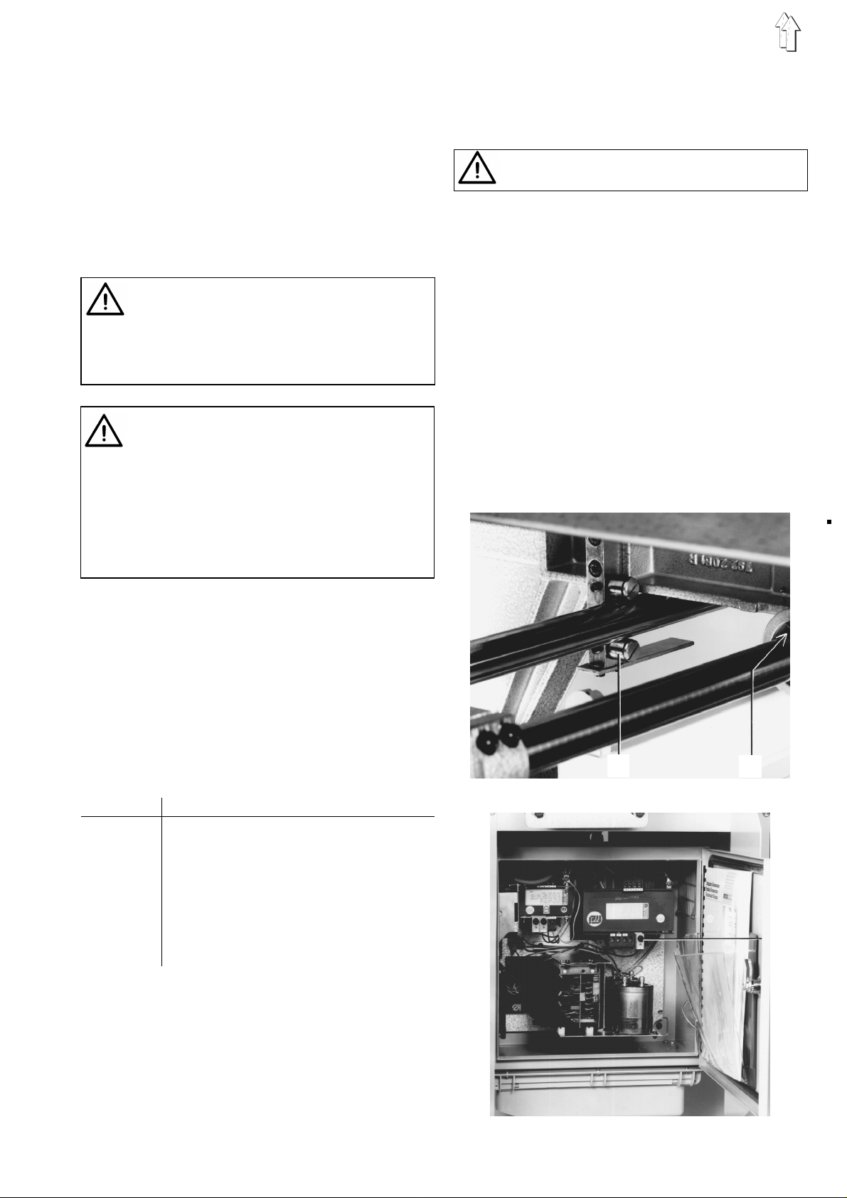
Transport carriag e
Caution in th e a r ea of mov in g m ac h ine part s
- Risk of Injury -
The transport carri ag e i s gu id ed on th e exten s io n
pipes at the f ron t by t he ba ll s le eves 2 and at t he
back by the track roller s 1.
They have been set tight at the factory. To remove
axial play only loos en th e excent rically beari ng ed
lower rollers 1 an d s e t t ig ht . Check for ease of
movement.
The transport carri ag e i s ad vanced by th e s t ep
motor for the following speeds: Stitch condensing,
Normal stitch length and transport carriage return.
Through a coding on the material stopper it is
possible by primary seams to reduce return speed
for a partial or complete run according to the rail
form. See 5.1.10 of the Micr o c on tro l s u mm ary.
Attention!
With some adjustments it is necessary to move the
transport carriage m anually.
This is possible with the main switch OFF.
When the main switch is ON, e.g. when the testing
program is to be us e d, th e s t ep motor is under
current and it s b ra k in g e ffect stops manual
movement. In this case the fuse 3 for th e s t ep
motor must be r em oved from th e c o nt r ol pa ne l.
For all adjustment s to pa rts form in g s t itches a
faultless needle mus t be us e d.
Upon request you will receive the following
adjustment gauges:
Order no. Application
933 80207 Dail gaug e
933 80193 Angle for the lo op er s ymmetry s et ti ng
933 80194 Indicator for the looper symmetry
setting
933 80200 Feeler gauge for the thread take-up
disk
933 80203 Gauge for the ho ok d rive housing
933 80221 Gauge for the rocker bolt in the h oo k
drive
An adjustme nt di s k in th e m a chine head has t he
notches A,B,C and D. An arresting pin, order no.
211700, for locking in to th e var io us a dj ustment
positions can be found in the package with the unit.
In conjunction with the letters on the handwheel the
arresting pin c a n b e p us h ed in to on e o f t he no tc h es
through a hole.
1
2
3
2.
3
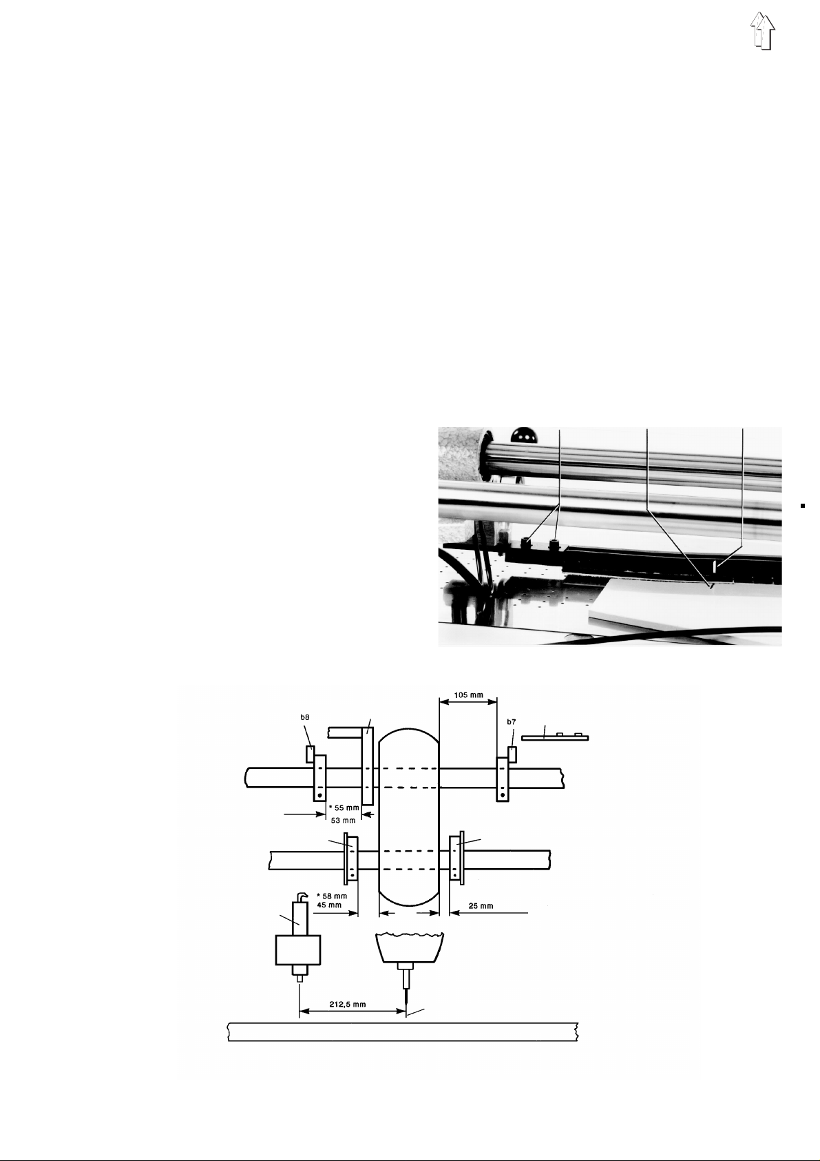
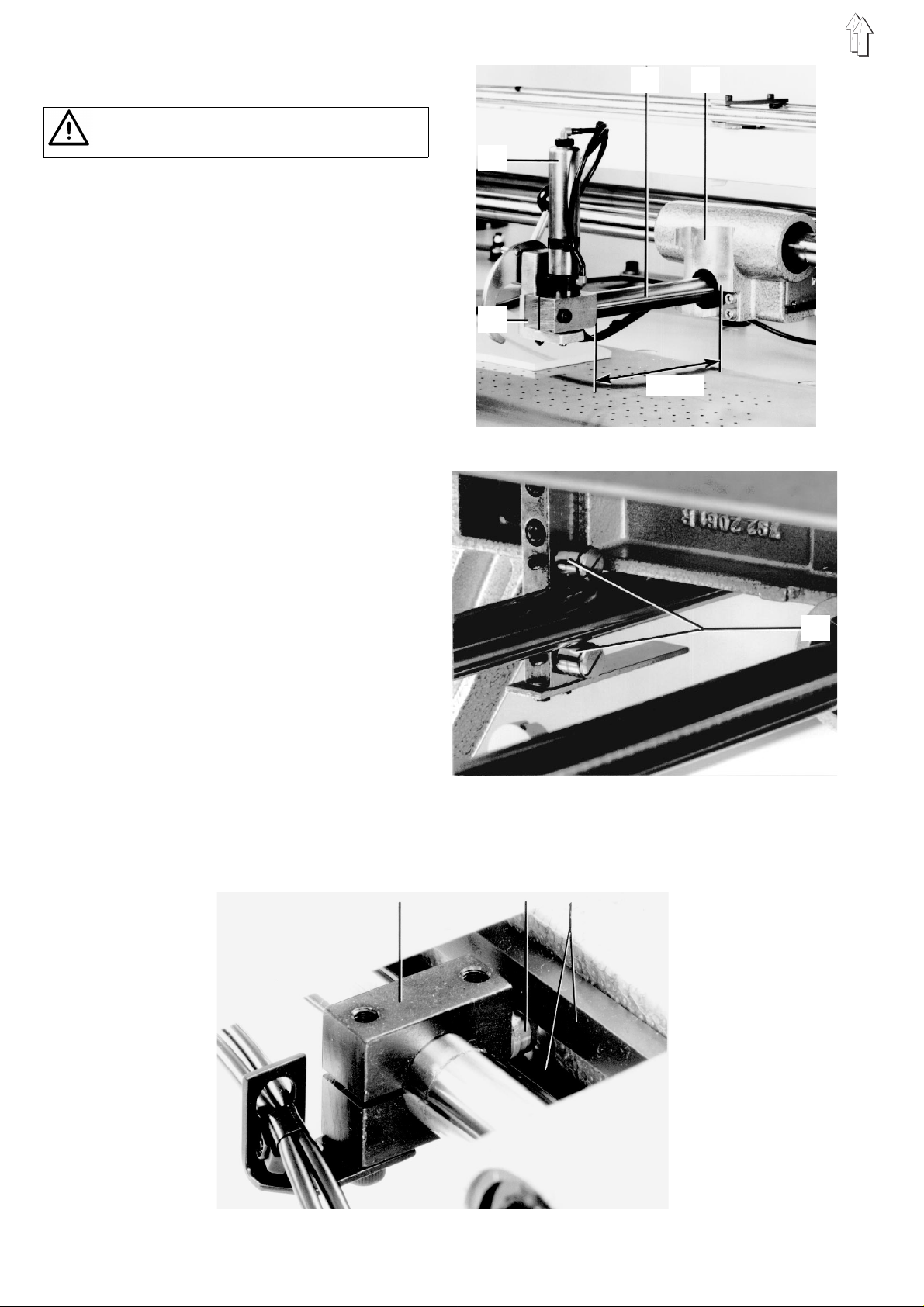
2.1_ Right End P osition
If the right position has been set with the L<-W->R
key, r ig ht diode bright, then the car riage will stop at
the right.
The distanc e b et wee n t he middle of the cy l in de r 4
and the middle of the needle should be 212.5_mm
in the right end position.
Main switch off
- Risk of Inju ry -
Preliminary A djus tme nts
– The b417.6 selector switch on the back of the
control unit front panel must be set closed for
1000 mm and ope n for 12 50 mm , a pp r op r ia te to
the rail length used.
– With the main switch Off, set the transport
carriage with the bracket 6 over the switch b7.
There must be a gap of 0.5 mm between the
bracket 6 and the switc h b 7.
Also between timing belt clamp 9 and switch b8.
– With lit right diode and a long tap of the
L<-W->R key, set the parameter value to 0 with
the numeric keypad.
– A gap of 10 5 m m mu s t b e s e t b et wee n the cast
guide 8 under the machine arm and the clamp
piece 5.
– In order to avoid a col lsi on of the transport
carriage w it h t he ma c hi ne he ad du ring a
malfunction of th e s t ep mo to r, the safety
stopper 7 is to be set at a distance of 25 mm
from the machi ne he ad at the right.
The distance of the safety stopper 11 at the left
behind the mach ine head should be 45 mm at
1000 mm sewing leng th and 58 mm at 125 0 m m
sewing length.
– Switch b8 serves as a safety switch. Its
distance fro m t he mo un ti ng pl at e 1 0 s h ou ld be
53 mm by 1000 mm sewing le ng th an d 55 mm
by 1250 mm sewing leng th .
All setting me as u rem en ts c a n b e s e en to ge th er
in the following dim en s io n s ket c h.
For the fine adjustme nt of the right end po s it io n
see the next page.
4
212,5 mm
5 6 b7
105 mm
25mm
8 7
11
b8
9
b8
10
4
Fine Adjustment
– Switch on ma in switc h.
– With the right diode lit an d a lo ng er t ap of th e
L<-W->R key, set the parameter to 0 with the
numeric keypad.
– Conduct a reference run by pressing the
<-O-> key. The carriage travels to the left.
When reachi ng th e switch b7 this is run pa s t by
a bit. The step motor switches over and at first
runs at low s pe ed to th e r e ference po int (b7)
and then runs with return speed to thr right end
position.
The distanc e b et wee n t he middle of the
cylinder 4 and the middle of the needle should
then be 212.5 mm. The right end position is to
be precisely set by adjusting the bracket_6 and
repeated referen ce runs.
Note!
This is the in itial carria ge position w hi c h mu s t b e
exactly adhered to i n o r de r to be able to alter n at e
work with different material guide rails.
2.3 Marking on the material guide rail
and the material stopper
The marking 3 on the rail and the marking 2 on the
material st op pe r must li e exac tly op po s it e e ac h
other. They show the extreme sewing length range
1000 or 1250 mm, that is, the seam end.
The curved rail contour must correspond to that of
the material stopper.
After loosening the screws 1 located at the left and
right the rail can be aligned in its slots to the
contour of the material stopper.
The carriage end position set at switch b7 may not
be changed for this pu rpose.
1 2 3
2.2 Left end position
Set the left position with the L<-W->R key. The left
diode lights up.
Conduct a refern c e r un w it h th e <- O -> key. The
carriage stops in the left end position. This position
corresponds to th e p os i ti on of th e switch b7 as
described in Section 2.1 . It must not be a lt er e d.
In order to avoid a co ll is i on of the carria ge by a
possible malfunct ion, the stopper 7 i s to be set at a
distance of 25 mm fr o m t he c as t pa rt 8. See
illustration in Sec. 2.1 and the dimension sketch.
Mounting pla te
Step mot or
Last
guide
under
Stopper for the right carriage end position
the head
bracket for the left end pos i t i on 212.5 mm
Stopper for the left carriage end position
Cylinder for the rail
Needle
Table-top
* Measure by long transport carriage (Sewing length 1250 mm)
5
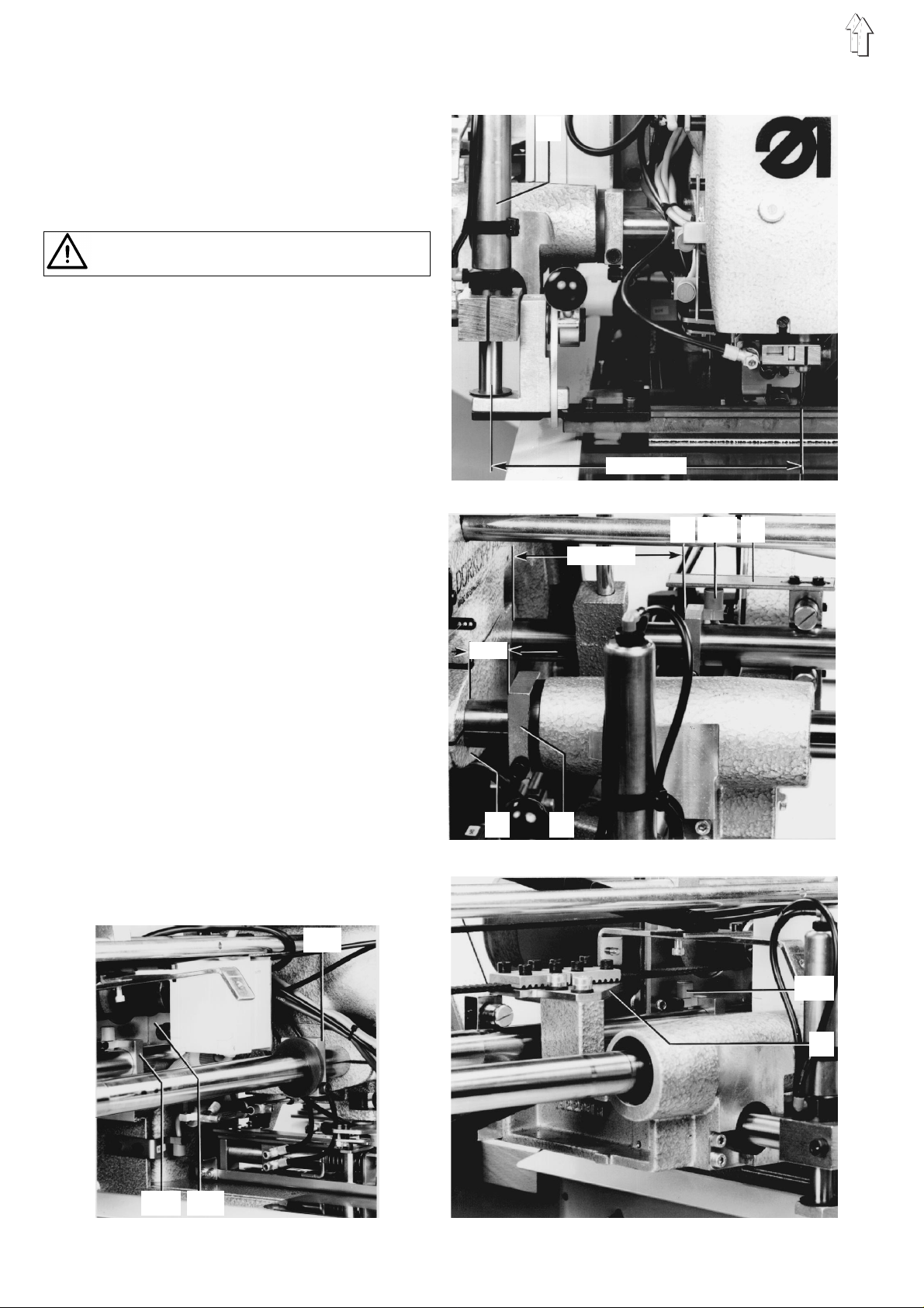
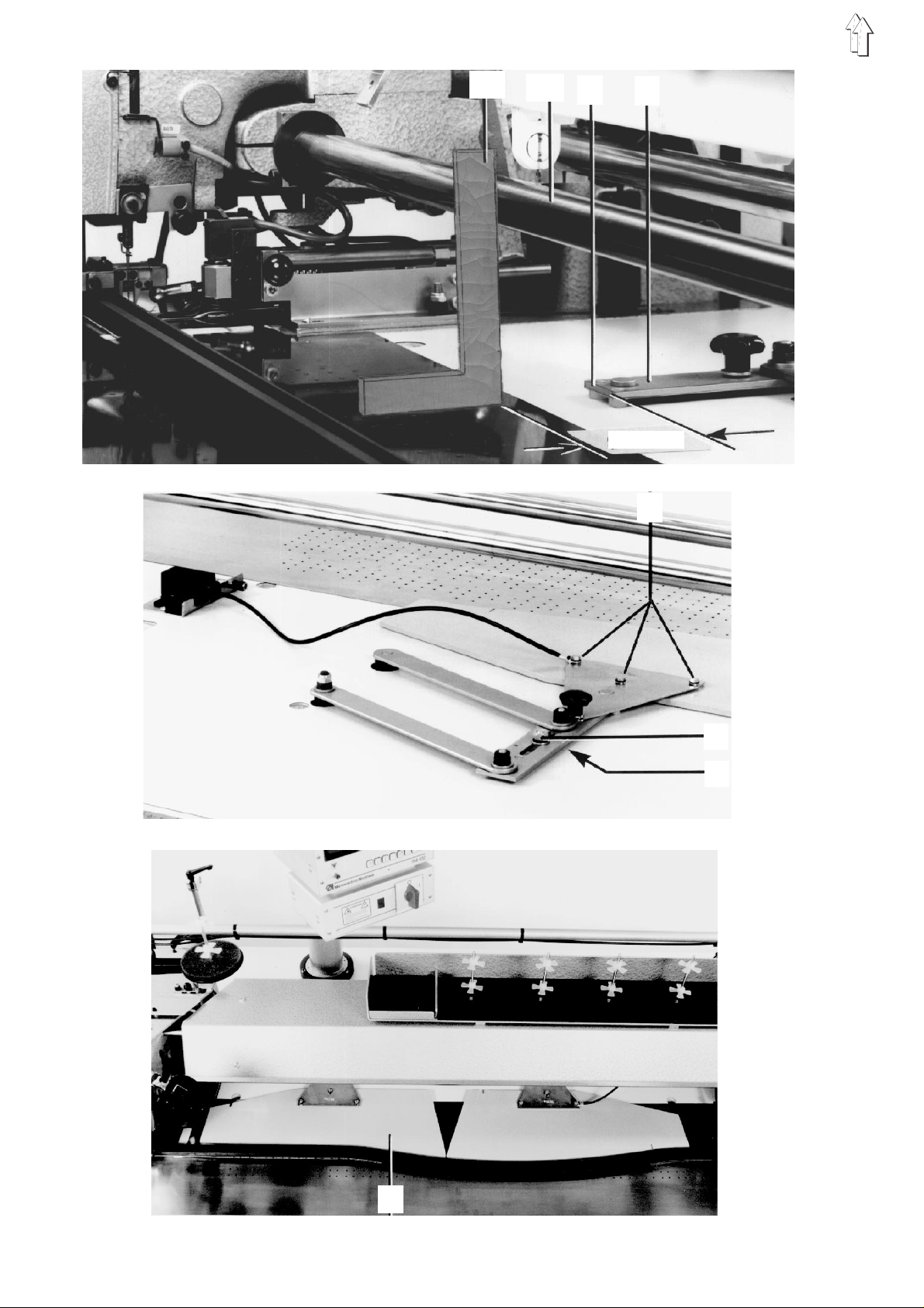
2.4 Transport Carriage Guide
Turn main switch off
- Risk of Inju ry -
With curved material guide rails the guide rod 2 is
moved within an allowable range crosswise to the
direction of sewing.
The range is properly set if there is a distance of
135 mm between the transport carriage 3 and the
clamping pis to n 4 wh en th e g ui de r od 2 i s pu ll ed to
its rest at the front of the unit.
For a perfect laying-on of the r ai l the guide rod
must be set tight and parallel to the table top.
– Loosen th e cl am pi ng pi ec e 8 a nd s et th e
dimension 135 m m.
– When tightening the clam pi ng piec e 8 t ake c a r e
that the str oke c y linder 1 is ver t i cal ly a li gn ed.
– Measure th e d is t an c e t o t he ma te rial slider bed
with the guide rod 2 in its forward and rear
positions.
– Should the distances not be equal, first loosen
the guide bead s 6.
– Achieve parallel is m of the guide rod 2 by
adjusting th e exce nt rically bear i ng ed guide
rollers 5.
This is to be performed appropriate to the
measurement r e sul ts s o th at fi r st o ne of the
rollers is loo sen ed and turned s lightly.
The transport carri ag e i s to be he ld ti gh t by t he
second roller.
– Set the guide rails 6 tight on roller 7.
Take care that the guide rod can still be easily
moved.
The left guid e r o d i s to be ad ju s ted in the same
manner.
2 3
1
4
135 mm
5
8 7 6
6
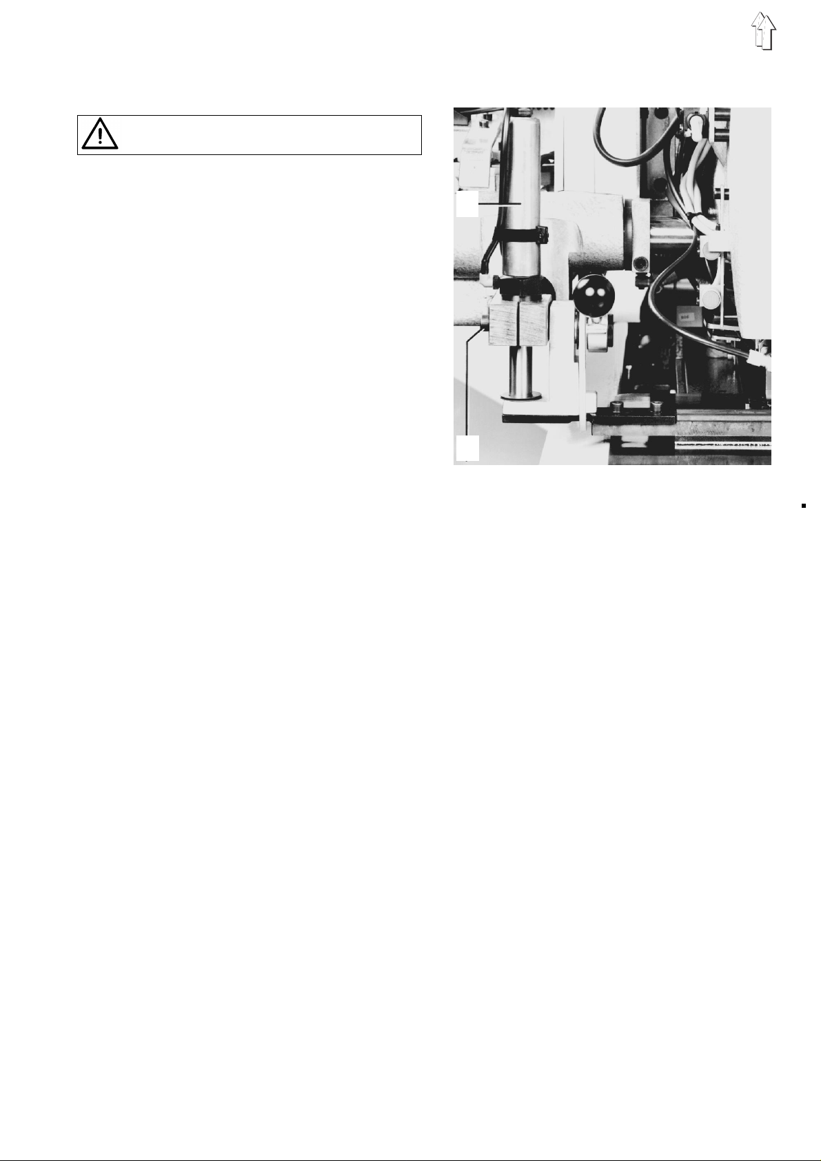
2.5 Stroke cylinder for the material
guide rail
Tur n main switch off
- R i sk of Injury -
A perfect laying-on of th e m at erial guide rail is
dependent on t he s et ti ng of th e s t r oke c yl in de r 1.
As descr ib ed in 2.4, the stroke cy l in de r 1 mu s t b e
set vertically.
The lowering stroke should be so dimensioned that
the materi al gu id e r ai l j us t ba r el y s ec u r el y lays o n
to the mater ial s li de r be d.
A stroke cylinder 1 set too low worsens the laying
on of the material guide rail.
The material guide rail, which is pretensioned
along its whole le ng th, could lift in the middle.
– Loosen screw 9.
– Set the height of the stroke cylinder 1
appropriately.
– Tighten s c rew 9 .
1
9
7
11
10
1
88 mm
2
3
4
5
6
8
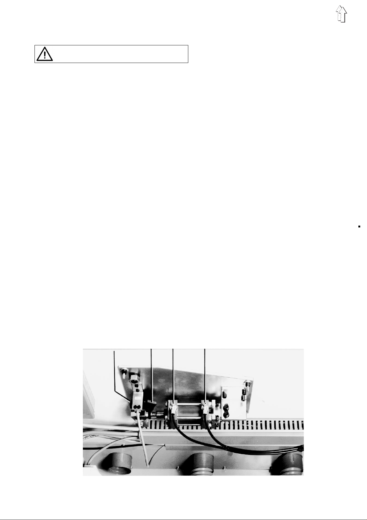
3._ Material stopper mounting and material stopper
Tur n main switch off
- R i sk of Injury -
The materia l st opper mounting 2 mu s t b e i n a
specific initial position in order to be able to
interchange m at erial stoppers for vari ou s s ea m
configurations without having to make further
adjustments.
At the stopper bolt 5 lying on the stopper there
must be a distance of 88_mm between the front of
the guide pipe_10 and the front edge_1 of the
material st op pe r mo un ti ng 2.
– Loosen nu t 4 .
– Move the stopper bolt 5 so that there is a gap of
88 mm between t he front edge_1 an d t he
angle_11.
– Tighten nut 4.
The equidista nt in te rval from the seam to the
material edge (seam interval) is determined by the
material st op pe r 6.
Prerequisite for the setting is that the adjustments
for the right transport carriage end position as per
Section 2.1 and the markings on the rail an d
material st op pe r as p er S e c ti on 2. 3 h ave been
carried out correctly.
– Loosen screw 3.
– Align the material stopper 6 so that there is an
equidistant seam interval between it and the
material guide rail along their complete length,
e.g. 10 mm.
– Tighten s c rew 3 .
The sewing unit can only be started when the
material stoppers have reached their end
position, thi s is, wh en th e switc h b3 for the le ft
stopper and t he switc h b 4 for th e right stopper
have been activated.
– Turn main switch on.
– Key in Program 63 on the "PROGRAM" switch
and activate with the S TOP key. Enter the
number 4 for switch b4.
– Push the s t op pe r al l t he way to the ba ck u nt il at
rest. - B4+ must appear in t he display.
– Should t his no t b e t he case then a gap of 0. 5
mm must be set between the contact maker 7
and the switch b4. Set contact maker so far
over the switch until B4+ appears.
– Set switch b3 in the same manner.
– The forward and b ack movemen ts o f t he
material s to pp er s s h ou ld be c on t inuous, not
jerky.
They can be adjusted at the throttle valves 8
and 9.
The right ma te rial stopper has an ad vanc e f un c ti on ,
this means that when the transport carriage has
passed the r i gh t m at erial stopper t his th en s ta rts its
movement to the front to again position the
material.
The timing is f ixed in th e c o nt r ol s.
b4 7 8 9
9