

Adler 743-221 Installation Instruction

Contents Page:
Home
Part 2: Installation Instructions Cl. 743-221
1. Scope of Delivery
2. General Information and Transport Safeguards
3. Installing the Sewing Unit
3.1 Transport of the Sewing Unit . . . . . . . . . . . . . . . . . . . . . . . . . . . . . . . . . . . . . 4
3.2 Setting the Working Height . . . . . . . . . . . . . . . . . . . . . . . . . . . . . . . . . . . . . . 5
3.3 Mounting for the Form Set . . . . . . . . . . . . . . . . . . . . . . . . . . . . . . . . . . . . . . 5
3.4 Attaching the Yarn Stand . . . . . . . . . . . . . . . . . . . . . . . . . . . . . . . . . . . . . . . 6
3.5 Checking the V-belt Tension . . . . . . . . . . . . . . . . . . . . . . . . . . . . . . . . . . . . . 6
4. Electrical Connection
4.1 Connecting the Microcontrol Control Unit . . . . . . . . . . . . . . . . . . . . . . . . . . . . . . 7
4.2 Checking the Nominal Voltage . . . . . . . . . . . . . . . . . . . . . . . . . . . . . . . . . . . . 7
4.3 Setting the Motor Protection Switch . . . . . . . . . . . . . . . . . . . . . . . . . . . . . . . . . 8
4.4 Checking the Direction of Rotation of the Motor . . . . . . . . . . . . . . . . . . . . . . . . . . 8
4.5 Checking the Positioning . . . . . . . . . . . . . . . . . . . . . . . . . . . . . . . . . . . . . . . 9
5. Pneumatic Connection
. . . . . . . . . . . . . . . . . . . . . . . . . . . . . . . . . . . . . . . . . . . 3
. . . . . . . . . . . . . . . . . . . . . . . . . 4
. . . . . . . . . . . . . . . . . . . . . . . . . . . . . . . . . . . . . . . . 10
6. Lubrication
7. Sewing Trial
. . . . . . . . . . . . . . . . . . . . . . . . . . . . . . . . . . . . . . . . . . . . . . 11
. . . . . . . . . . . . . . . . . . . . . . . . . . . . . . . . . . . . . . . . . . . . . . 12

2
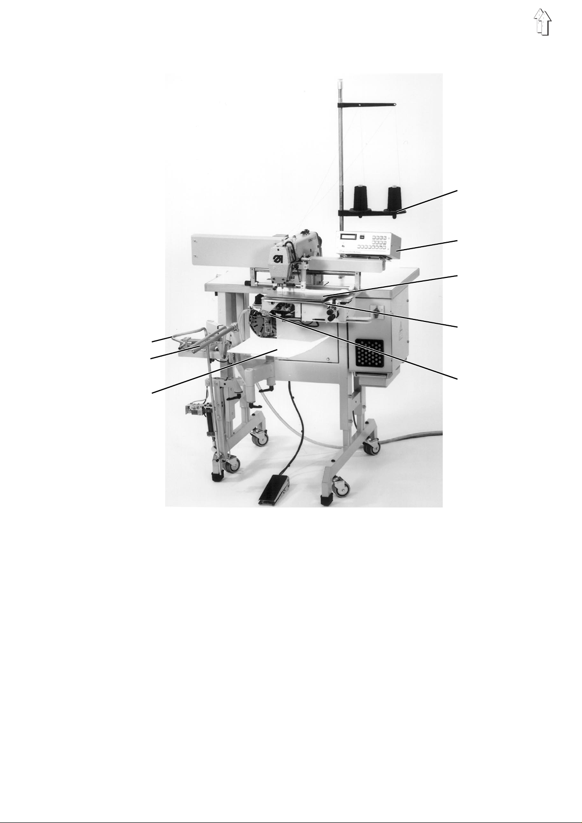
1. Scope of Delivery of the Sewing Unit
1
4
5
6
7
2
8
3
The scope of delivery is dependent on your order.
Before inst al l a tion please check i f al l re qu i r ed pa rt s a r e p r ese nt.
Standard equipment and optional equipment:
–
1
Smoother dev i c e
–
2
Bundle clamp with slewing arm and holder pipe
–
3
Placement t ab l e
–
4
Ya rn sta nd
–
5
Microcont rol c o nt r ol u ni t
–
6
Form set
–
7
Folding table
–
8
Blower pip e f r om ab ov e an d/ or f rom the right
–
Small parts in the accessories pack
3
2. General Information and T ransport Safeguards
ATTENTION !
The sewing unit may only be installed by trained, skilled personnel.
All work on the electrical e qu i pm en t o f t he s ew i ng un i t m ay o nl y b e
conducted by electricians or appropriately instructed persons.
The mains plug must be pulled.
The operatin g i n st ru c ti o ns f or the sewing driv e an d the step motor
drive are to be observed.
Before installation of the sewing unit the following
safeguards
–
The securing band from the sewing drive.
–
The angles which on the wooden pallet lock over the feet of the
frame.
–
Securing bands of the smoother and bundle clamp.
–
Securing bands of the placement table.
3. Installation of the Sewing Unit
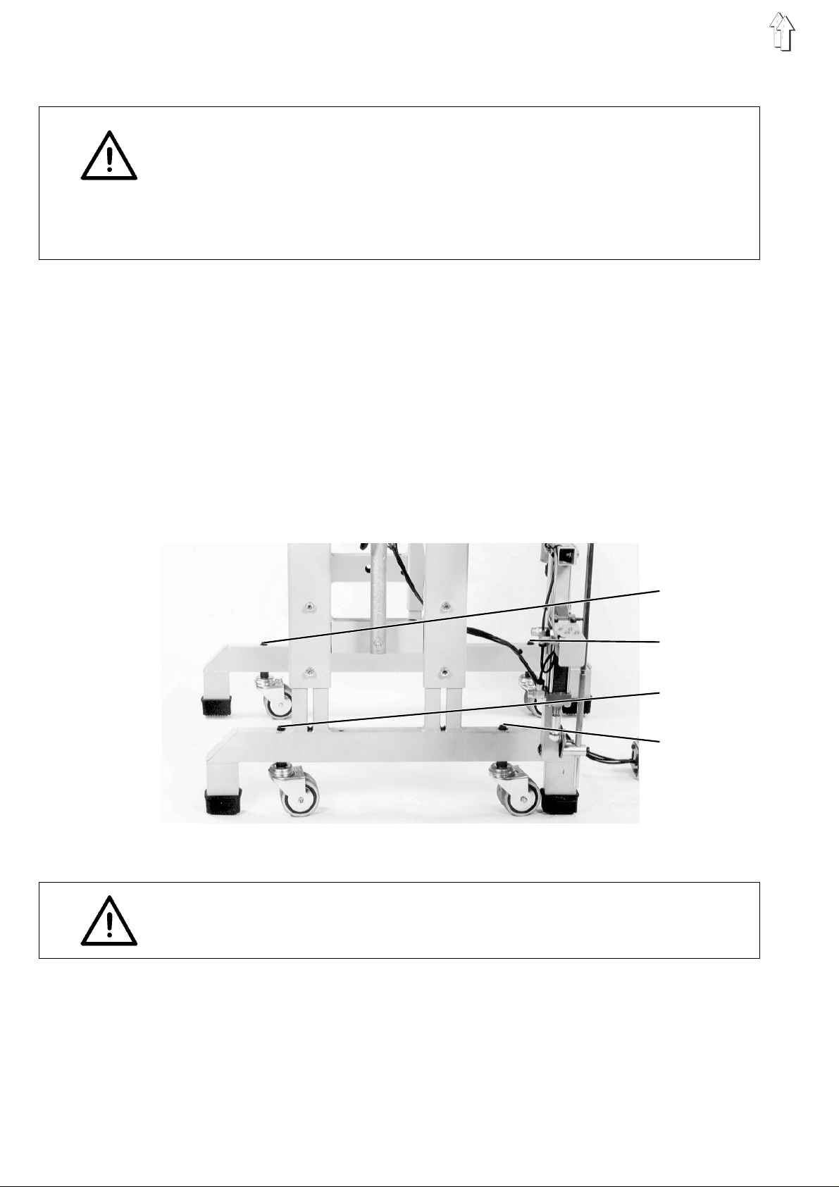
3.1 T ransport of the S ewing Unit
transport
are to be remov e d:
1
2
3
4
The sewing unit has 4 castors for in-house transport.
ATTENTION !
During opera ti o n o f t he s ew i ng un i t t he c as t or s m us t be turned in so
far that the unit rest s firm l y on i ts f ee t.
–
For transport turn the setting screws 1 to 4
The feet must h av e en ou gh fl o or c learance for tra nsport.
–
Transport the sewing unit.
–
To lower the sewi ng un i t t urn the setting scr ew s 1 t o 4
The feet must rest firmly on the floor.
4
to the left
.
to the right
.
 Loading...