

Page 1

Contents Page
Home
Part 4: Instructions f or pr ogramming D A-Micr ocontr ol cl. 743-121
Progra m version : 7 43LC-A0 3
1. General . . . . . . . . . . . . . . . . . . . . . . . . . . . . . . . . . . . . . . . . . . . . . . . . . 3
2. Description of the Controls
2.1 Operating Elements on the Front Panel . . . . . . . . . . . . . . . . . . . . . . . . . . . . . . . 4
2.2 Operating Elements in the Controls . . . . . . . . . . . . . . . . . . . . . . . . . . . . . . . . . 5
3. Setting the Sewing and Testing Programs
3.1 Display of the Program Version . . . . . . . . . . . . . . . . . . . . . . . . . . . . . . . . . . . . 6
3.2 Sewing Programs . . . . . . . . . . . . . . . . . . . . . . . . . . . . . . . . . . . . . . . . . . . 6
3.3 Setting Blower Times . . . . . . . . . . . . . . . . . . . . . . . . . . . . . . . . . . . . . . . . . 7
3.4 Step Motor Controller Test . . . . . . . . . . . . . . . . . . . . . . . . . . . . . . . . . . . . . . 7
3.5 Timer and Memory Test . . . . . . . . . . . . . . . . . . . . . . . . . . . . . . . . . . . . . . . . 7
3.6 Current Passage Check . . . . . . . . . . . . . . . . . . . . . . . . . . . . . . . . . . . . . . . . 8
3.7 Test of the Front Panel Elements . . . . . . . . . . . . . . . . . . . . . . . . . . . . . . . . . . . 8
3.8 Test of the Input Elements . . . . . . . . . . . . . . . . . . . . . . . . . . . . . . . . . . . . . . . 9
3.9 Selecting the Input Elements . . . . . . . . . . . . . . . . . . . . . . . . . . . . . . . . . . . . . 9
3.10 Selecting the Output . . . . . . . . . . . . . . . . . . . . . . . . . . . . . . . . . . . . . . . . . 10
3.11 Positioning the Machine Head in the 2nd Needle Position . . . . . . . . . . . . . . . . . . . . . 10
3.12 Positioning the Machine Head in the 1st Needle Position . . . . . . . . . . . . . . . . . . . . . 11
3.13 Positioning the Machine Head without Thread Trimming . . . . . . . . . . . . . . . . . . . . . . 11
3.14 Positioning the Machine Head with Thread Trimming . . . . . . . . . . . . . . . . . . . . . . . . 11
4. Operation Displays and Error Messages . . . . . . . . . . . . . . . . . . . . . . . . . . . . . 11
5. Step Motor Output . . . . . . . . . . . . . . . . . . . . . . . . . . . . . . . . . . . . . . . . . . 12
5.1 Status display . . . . . . . . . . . . . . . . . . . . . . . . . . . . . . . . . . . . . . . . . . . . . 12
Page 2

2
Page 3

1. General
The DÜRKOPP ADLER 743-121 controls, with the int egrat ed MU LTITEST testing and monitoring system, assumes control and supervision
of the sewing process. Operating errors and malfunctions are displayed.
Special programs simplify mechanical adjustments and allow a quick
checking of the i np ut an d o ut pu t e le me nt s.
The data is sh own i n a 2 • 16-digit display.
All functions c an be al te r ed by pres sin g th e ap pr o priate button. The
machine must be in its in it ial setting. The set values (seam leng th , fu nction on/off, etc.) are put into the memory (battery- powered buffer)
and activated when th e m ac h in e i s next switche d o n.
3
Page 4
2. Description of the Controls
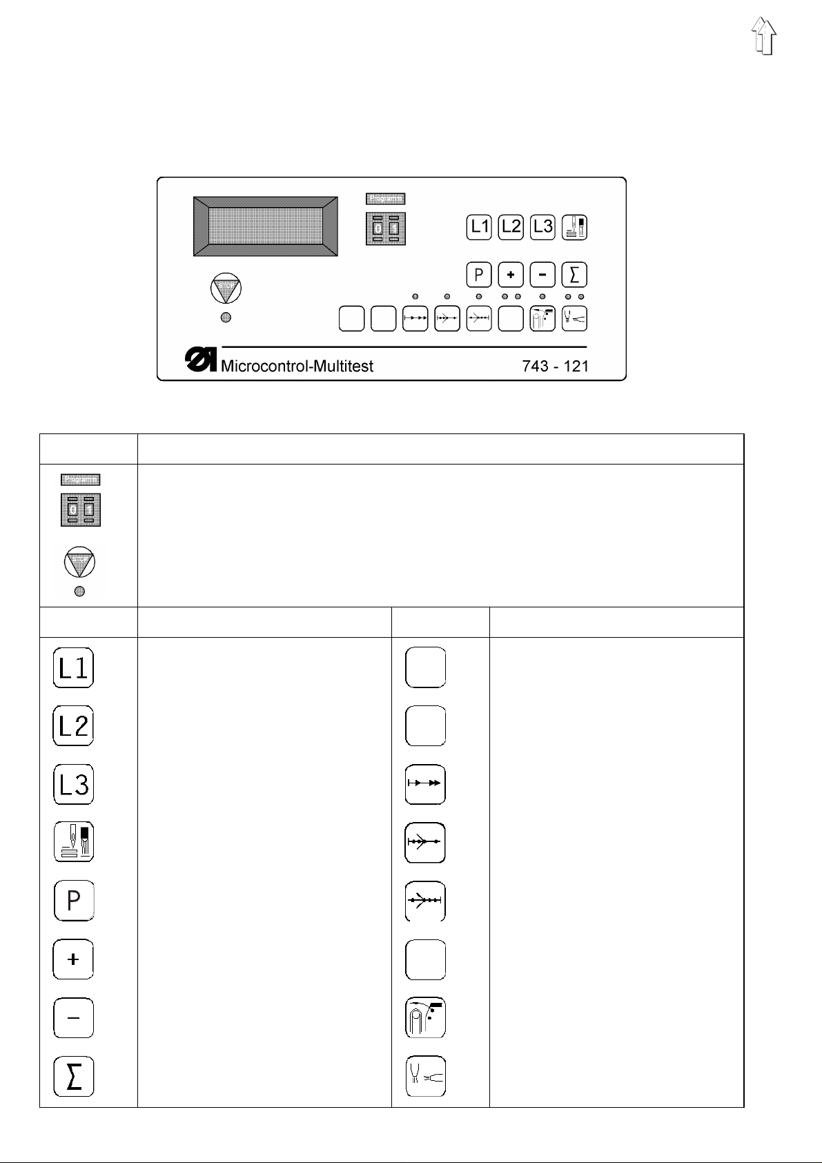
2.1 Operating El ements on t he Fr ont P ane l
Button Description
Selecting the sewing and testing programs
Stopping th e cu r r en t p rogr am
Activating the se lected program
Button Description Button Description
Seam length 1
Seam length 2
Seam length 3
Seam length v ia li gh t b a rrier
Normal stitch /
Stitch condensing stitch
- Reserve -
- Reserve -
Soft start
Stitch condensing at the seam
beginning
Stitch condensing at the seam end
Increase value
- Reserve -
Decrease value
Set counter
Start test program
4
Smoother
Blower from above/be low
Page 5
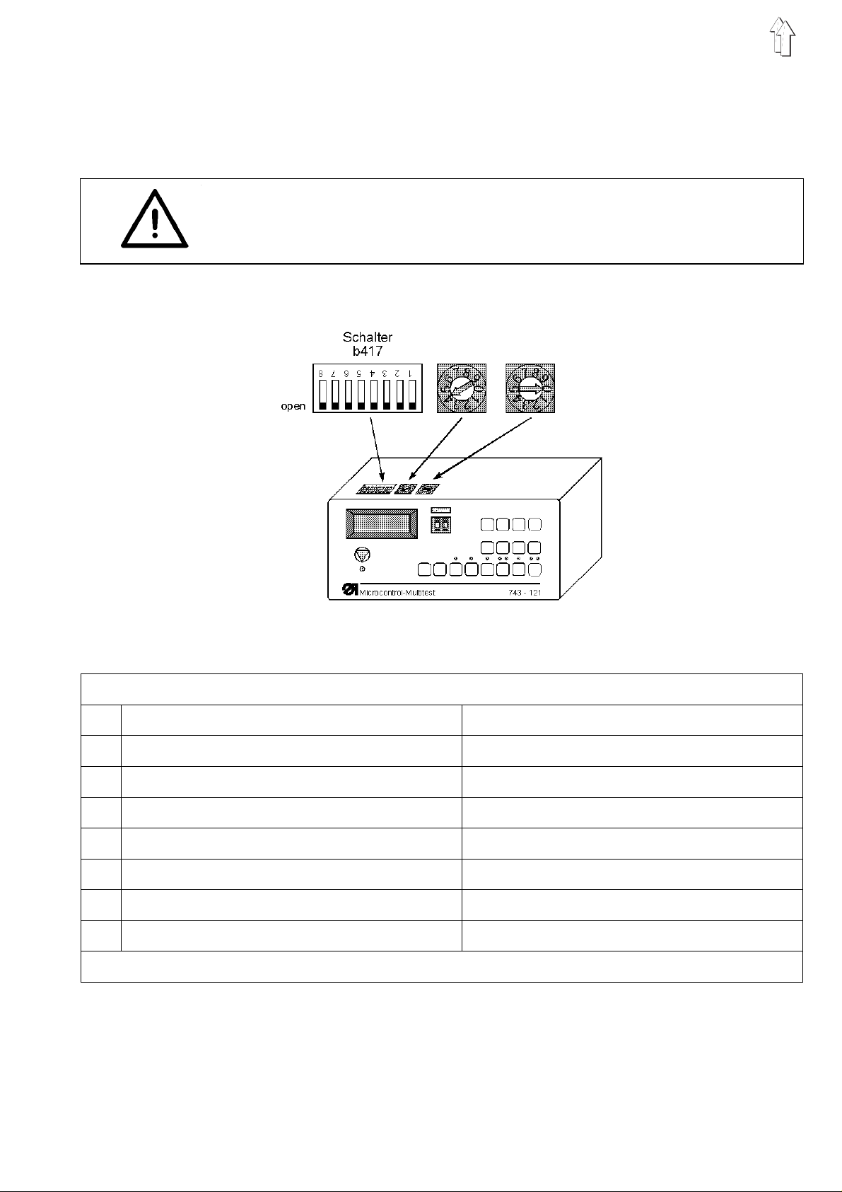
2.2 Operating Elements in the Controls
The switch b417 in the control must be set suitably for the individual
work methods.
The dials b401 un d b 40 2 a r e w it ho ut fu nc t io n f r om version " A 03 " .
Caution Current !
The switches may only be changed when the main switch is turned off.
Switch b417 open clo sed
1 Smoother - Reserve 2 Thread monitor activ Thread monitor not activ
3 - Reserve - - Reserve 4 Nmax. = 4.800 RPM Nmax. = 4.300 RPM
5 Chain stitch - Reserve 6 - Reserve - - Reserve 7 - Reserve - - Reserve 8 - Reserve - - Reserve Initial position = all switches in open status
5
Page 6

3. Setting the Sewing and T esting Pr ograms
The sewing and testing programs are selected via the
" Programm " preselector switch.
Switch Function
Program
00
01
02
40
57
59
60
61
62
63
64
66
67
68
69
–
Set " Programm " switch t o t he desired program.
–
" Turn on main switch " or press the " STOP " button.
The selected program is activated.
If the " P? " message appears, then an illegal program has been set.
Correct the setting and press the " STOP " button.
3.1 Display of the Pr ogram Version
Display of the program version
Sewing program e.g. dar t
Sewing program e.g. waist pleat
Setting the blower tim es
Step motor c on tr o ll er t es t
Timer and mem ory test
Current pa s s ag e c h eck
Test of the fron t p an el el em en ts
Test of the input el em en ts
Selecting th e i np ut el em en ts
Selecting the output elements
Sewing drive: Set value X, Pos. 2
Sewing drive: Set value X, Pos. 1
Sewing drive: Set value X, Pos. 1 Pos. 2
Sewing drive: Set value X, thread trimming,Pos.2
3.2 Sewing Pr ogram
The program version an d a c he ck su m a r e s h own i n t he di s play.
e.g.: 743A01 743 = class designation
A01 = code let te r an d s e r ia l nu mb er
All program version s wi th th e s a me c las s de s ignation and the same
code letter but a hi gh er serial number replac e al l l ower num be r ed versi ons ( e.g.: 743A03 replaces 743A01 and 743A02 ).
The check sum is o nl y me an t for use by th e facto ry servi c e d ep artment. This value shows whether the complete machine program is installed prop erly in the program me mo ry.
–
Set " Programm " switch to " 00 ".
–
Press " STOP " button.
The program is a c ti vated .
The 01 sewing pr ogram or t he 02 s ewing pro gra m c a n b e c a lled up.
The operating procedure is described in the operating instructions.
–
Set " Programm " switch to " 01 " or " 02 ".
–
Press " STOP " button.
The sewing program is activated.
6
Page 7

3.3 Set blower times
3.4 Step Motor Controller T est
The blower period for blowing out the piece to be sewn are adjustable.
–
Set " Programm " sw itch t o " 40 ".
–
Press " STOP " button.
The program is activated. The blower time is displayed.
–
The desired value is set with the " + " and " — " button s.
Adjustment ra ng e: 01...20 = 0, 1. ..2,0 seconds
This program ch ecks th e s t ep mo to r c on tro ll er a nd th e s t ep mo to r ou tput levels.
–
Set " Programm " sw itch t o " 57 ".
–
Press " STOP " button.
The test program is activated. The results are displayed.
Display Explanation
3.5 Timer and Memory T est
AMP ERR
LINK OK
LINK ERR
EPROM OK
EPROM ERR
XCOU OK
XCOU ERR
SCOU OK
SCOU ERR
CAUTION !
This program completely erases t he me mory.
Sewing lengths, blower ti me s an d a ll other values must be set anew.
The RAM and the timer switchings are checked automatically by the
program.
–
Set " Programm " sw itch t o " 59 ".
–
Press " STOP " button.
The program is ac t ivated.
Fault in the power output
Transmission cable not plugged in
Transmission to the controller OK
Fault in the transmission
EPROM OK
EPROM defective
Counter component for pulse counting OK
Counter compo ne nt for pul s e co un ti ng de fective
Counter component for pulse generation OK
Counter component for pulse generation defective
Display Explanation
OK
ERROR 0
ERROR 6
ERROR 7
RAM and timer OK
RAM-error
Timer 1 defective
Timer 2 defective
7
Page 8

3.6 Current P as sage Che c k
1. This program checks to see if the 24 V power unit supplies current
when the output drivers are switched off.
2. The program checks all output elements, the output drivers and the
installation for current passage.
–
Set " Programm " switch to " 60 ".
–
Press " STOP " button.
The program is a c ti vated .
Display Explanation
V?
S17
(Example)
3.7 T est of the Front P anel Elements
The program checks the front panel elements.
–
Set " Programm " switch to " 61 ".
–
Press " STOP " button.
The program is a c ti vated .
1. Check buttons
–
Press the button to be tested.
The display shows the allocated value.
e.g. P61 8 (allowable values: 1, 2, 4, 8 )
2. Check LED s
–
Set " Programm " switch to " 61 .. .6 8 " .
–
Press " Σ " butt on.
The selected diode will light up.
Shor t c i r cui t i n t he in s ta ll at io n o r an output driver is de fective.
Interru pt io n i n the output elemen t S 1 7, in its installation od er d river.
Continue the i ns p ection at the next element by
pressing th e " Σ " butt on.
No. LED
61
62
63
64
65
66
67
68
8
Stitch co nd en s in g a t t he be gi nn ing of the seam
- Reserve Soft start
Blower from above
Blower from underneath
Smoother
- Reserve Stitch condensing at the seam end
Page 9

3.8 T est of the Input Elements
The program check s th e status of the input e le me nt s.
–
Set " Programm " sw itch t o " 62 ".
–
Press " STOP " button.
The program is ac t ivated.
–
Operate input el em en t.
If any input element is operated, then the display will show the circuit
diagram designa ti on an d i ts s t at us.
The display changes when any other input element is operated.
e.g.: b03+ The switch for "Table forward" is switched on.
+ means:
contact switch = open contact
proximity switch = metal in front of the switch
reflecting light barrier = no reflection
transmitted light barrier = beam not broken
Input Designation
Element
3.9 Selecting the Input Elements
CAUTION !
All input elements are carefully set at the factor y.
Adjustment an d c o r rec t io n c a n o nl y be un de rtaken by trained se rvice
personnel.
The program is used to set the input elements.
–
–
–
–
b03
b04
b05
b07
b15
b16
b45
Set " Programm " sw itch t o " 63 ".
Press " STOP " button.
The program is ac t ivated.
Set " Programm " switch to the desired input element (see section
3.8).
Adjust the input element (switch flag, control cam, etc.) until the de-
sired status i s di spl ayed.
Tabl e forward
Sewing released
Transport carriage left
Transport carriage right
Form assembly slew
Form assembly control
Light barri er s e am en d
9
Page 10

3.10 Selecting th e Output El ements
Caution Danger of Injury !
Do not put your hands into the machine while it is operating.
Choose your position so that no injury is possible
(e.g. Function check s17: Table back).
The program checks the function of an output element.
–
Set " Programm " switch to " 64 " .
–
Press " STOP " button.
The program is a c ti vated .
–
Set " Programm " switch to the output element.
–
Press " Σ " butt on.
The selected output element is switched on.
–
Press " Σ " butt on.
The selected output element is switched off.
Output Designation
Element
s17
s18
s19
s 9
s10
s25
s28
s29
s30
s31
s32
Table back
Table free
Thread tension
Blower from right
Blower from above
Smoother
Trimmer
Sle w form as semb l y
Trimmer trans po rt and
Pressure increase for thread clamp
Release thread chain
Low er form assembly
3.11 P osit ioning the Ma chin e Head in t he 2nd Needle P o sition
The machine head is positioned in the 2nd position (needle up) with
this program.
–
Set " Programm " switch to " 66 ".
–
Press " STOP " button.
The program is a c ti vated . Display " SW? "
–
With the " Programm " switch s e t t he drive revolutions to " 01 "...
" 13 " .
01 = Minimum revolutions
13 = Maximum revolutions
–
Press " Σ " button and hold down.
The drive runs at th e s elec t ed revolutions. The actual revolutions
will be displayed after a few seconds.
After the " Σ " button is released the needle is positioned in the
2nd (needle up) position.
10
Page 11

3.12 Positioning the Machine Head in the 1st Needle Position
The machine he ad is p oi s it io ne d i n the 1st position ( n ee dl e down) with
this program.
–
Program procedure and description as 3.11.
Positioning is in the 1st position.
3.13 Positioning the Mac hine Head without Thread T rimm ing
The operation is as described under program P66, but the positioning
of the machin e h ea d o c cur s i n t he 1s t ne ed le po s it io n (n ee dl e d own) .
–
Set the "program" switch to "68".
–
Press the "STOP" key.
8
The program is ac t ivated.
After a short break the needle positions in the 2nd needle position
(needle up).
3.14 Positioning the Machine Head with Thread T rimming
The operation is as described under program P66, but the positioning
of the machine head occurs in the 2nd needle position (needle up).
–
Set the "program" switch to "69".
–
Press the "STOP" key.
9
The program is ac t ivated.
During the last half machine head revolution thread trimming occurs.
11
Page 12

4. Operation Displays and Err or Messa ges
Display Explanation Comments
P?
743A01
---REF--->
REF--->
---x--POS-ERR
--( )-SW?
E2
STOP
b417
b16
b4
SMC-TEST
AMP ERR
LINK OK
LINK ERR
EPROM OK
EPROM ERR
XCOU OK
XCOU ERR
SCOU OK
SCOU ERR
Illegal progra m
Display of the program version
Run to reference point
Run to reference point
Thread breakage
Motor not turning
No signal from the position transmitter
invalid r evol u tion level s e t
Fuse E2 on the control trans former defective
Stop button defective
Glide plate not locked in
invalid switch position from b417
Form assembly not present
Sewing released
Step motor controller is being tested
Fault in the power ou tput
Transmission cable no t pl ug ge d in
Transmission to controller OK
Error in data transfer
EPROM OK
EPROM defective
Counter componen t for pulse co un ti ng OK
Counter comp. for pulse counting defective
Counter compon en t for pulse ge ne ra ti on OK
Counter comp. for pulse generation defective
Set
" Programm "
-
-
Reinsert thread
Check motor protection switch
Check position tran sm it te r
Set
" Programm "
Replace fuse
Replace stop button
Lock-in glide plate
Set b417 switch anew
Insert form assembly
-
Call factory service dept.
Plug in transmission cable
Call factory service dept.
Install new EPROM
Call factory service dept.
Call factory service dept.
switch anew
switch anew
ERROR 0
ERROR 1
ERROR 2
ERROR 3
ERROR 4
ERROR 5
ERROR 6
ERROR 7
ERROR B5
ERROR B45
Error Bxx
PROG
ERROR 1
PROG
ERROR 2
RAM-error
Fault in the input elements
Fault in the front panel elements
Program switch defective
Error in data transfer to sewing drive
controller
Short voltage drops in the mains
Timer 1 defective
Timer 2 defective
Transport carriage lef t (en d po si ti on)
Light barrier (no sewing material present)
Fault in input element Bxx
Error in the values in the memory
Error in putting the check sum into memory
Call factory service dept.
Check input elements
Check front panel el em en ts
Replace progra m switch
Call factory service dept.
Stabilize voltage supp ly
Call factory service dept.
Call factory service dept.
Manually push into the initial position
Insert sewing material
Bxx defective or mis-adjusted
Reset seam lengths, blower tim es, etc.
Program not pro pe r ly s tor ed in me mo ry
12
Page 13

1
2
5
3
6
4
13
Page 14

5. Step Motor Output
Caution Electric Current !
Turn the main switch off !
The switches may not be adjusted carrying currrent.
5.1 Status Dis pla y
The switches must be in the positions shown !
1 = Step motor output
2 = Status indicators see Chapter 5 .1
3 = Parameter switches see Illustration
4 = Current selector F
5 = Voltage convertor 230 V
6 = Operation light on / off
LED 1 Undervoltage
Shor t fall in t he operating voltage of m ore than 30 %
LED 2 Phase monitoring
Interrupti on in on e o r mo re m otor wires
14
LED 3 Short circuit
Short circuit between two or more motor phases
or motor phase and ground
LED 4 Overheating
Exceeding the allowable temperature of the unit
LED 1 and 2 Reset
ENABLE in pu t is no t a c ti vated by the c o nt rol s
 Loading...