


739-23
Additional Instructions for the Manufacture
of Material Clamps
Manufacture and Installation
Postfach 17 03 51, D-33703 Bielefeld • Potsdamer Strae 190, D-33719 Bielefeld
Telefon (0521) 925-01 • Telefax (0521) 925 13 15


Contents Page:
Additional Instructions for the Manufacture of Material Clamps Class 739-23
1. Introduction ................................................. 3
2. Kits ...................................................... 5
2.1 Flap kit (0739 417524) ........................................... 5
2.2 Waistband extension kit (0739 41534) .................................. 7
3. Manufacture of material clamps .................................... 8
3.1 Determination of seam coordinates.................................... 8
3.1.1 Positioning seam templates for flaps on the contour templates ................... 10
3.1.2 Positioning seam templates for waistband extensions on the contour templates ......... 11
3.2 Transferring contours of material clamps to contour templates ................... 12
3.3 Transferring stitching contours to stitching plates ........................... 13
3.4 3.4 Infeed and exit of edge cutter ..................................... 14
3.4.1 Infeed and exit of material clamps for flaps ............................... 14
3.4.2 Infeed and exit of material clamps for waistband extensions..................... 15
3.5 Trimming of bed-plate, intermediate sheet and clamping plate ................... 16
3.6 Manufacture of fullness plates....................................... 17
3.7 Drill holes for clamping elements ..................................... 18
3.7.1 Holes in material clamps for flaps..................................... 18
3.7.2 Holes in material clamps for waistband extensions .......................... 19
3.8 Unlocking of clamping plate (material clamps for flaps)........................ 20
3.9 Position of material stops ......................................... 21
3.10 Slots in intermediate plate for material clamps for flaps ....................... 23
4. Assembly of material clamps ...................................... 24
4.1 Bed-plate ................................................... 24
4.2 Fullness plate ................................................ 24
4.3 Adhering of foam strips to clamping plate ................................ 25
4.4 Installation of tension lever ........................................ 25
4.5 Installation of clamping plate ....................................... 26
4.6 Installation of material stops ........................................ 26
4.7 Installation of holder and transponder .................................. 27
4.8 Application of sliding foil .......................................... 28
1
2
1. Introduction
This manual describes the manufacture of material clamps for the
739-23
sewing machine in appropriate sequence.
The following kits are available:
No. Description Parts No.
1 Flap kit 0739 417524
2 Waistband extension kit 0739 417534
CAUTION!
Only authorised and instructed personnel may carry out the operations
described in this manual!
Caution! Risk of injury!
Use the standard clamping and safety devices (goggles etc.) for cutting
to size and processing of prefabricated plates and sheets.
5-3
22
8
6
7
9
10
4
5
11
3
12
2
13
1
14
16
21
23
20
18
15
5-4
19
17

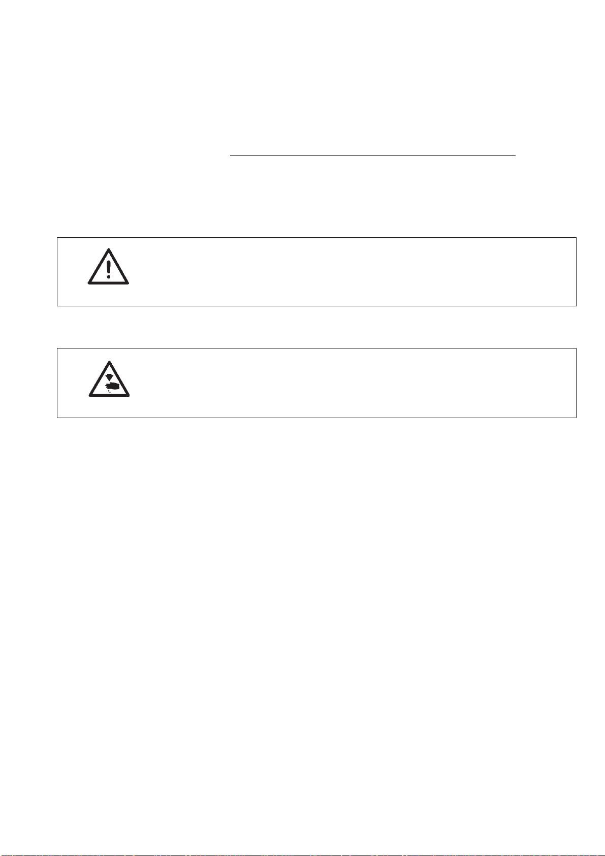
2. Kits
2.1 Flap kit (0739 417524)
The kit contains the following parts:
Item Part No. Description
1 0739 41003 0 Bed-plate
2 0739 41005 0 Intermediate plate
3 0739 41004 0 Clamping plate
4 0739 41007 0 Fullness plate
5 9129 02303 0 Straight pin
6 0739 41001 0 Plastic holder
7 9835 90100 3 Transponder
8 0739 41009 4 Clamping element
9 9049 04100 9 Adhesive
10 Small parts
11 0739 41008 3 Foamed strip
12 0739 41018 0 Long threaded shackle
13 0739 41006 0 Threaded shackle
14 0699 97392 7 Sliding foil
15 0739 41017 0 Material stop
16 (20, 21) 0739 00505 5 Distance piece
17 Screws, nuts,
washers
18 0739 00541 7 Intermediate ring
19 9830 50200 5 Distance bolt
20 0739 00505 6 Push rod
(14) 0699 98914 8 Adhesive tape (double-sided)
0990 31002 3 Sanding paper
21 9357 00009 0 Locking washer
22 0739 410190 Bushing
23 0739 410200 Pointing plate
5-5
5
6
7
8
4
9
3
2
15
14
11
10
13
17
18
16
1
19
21
12
15
20
23
22
5-6

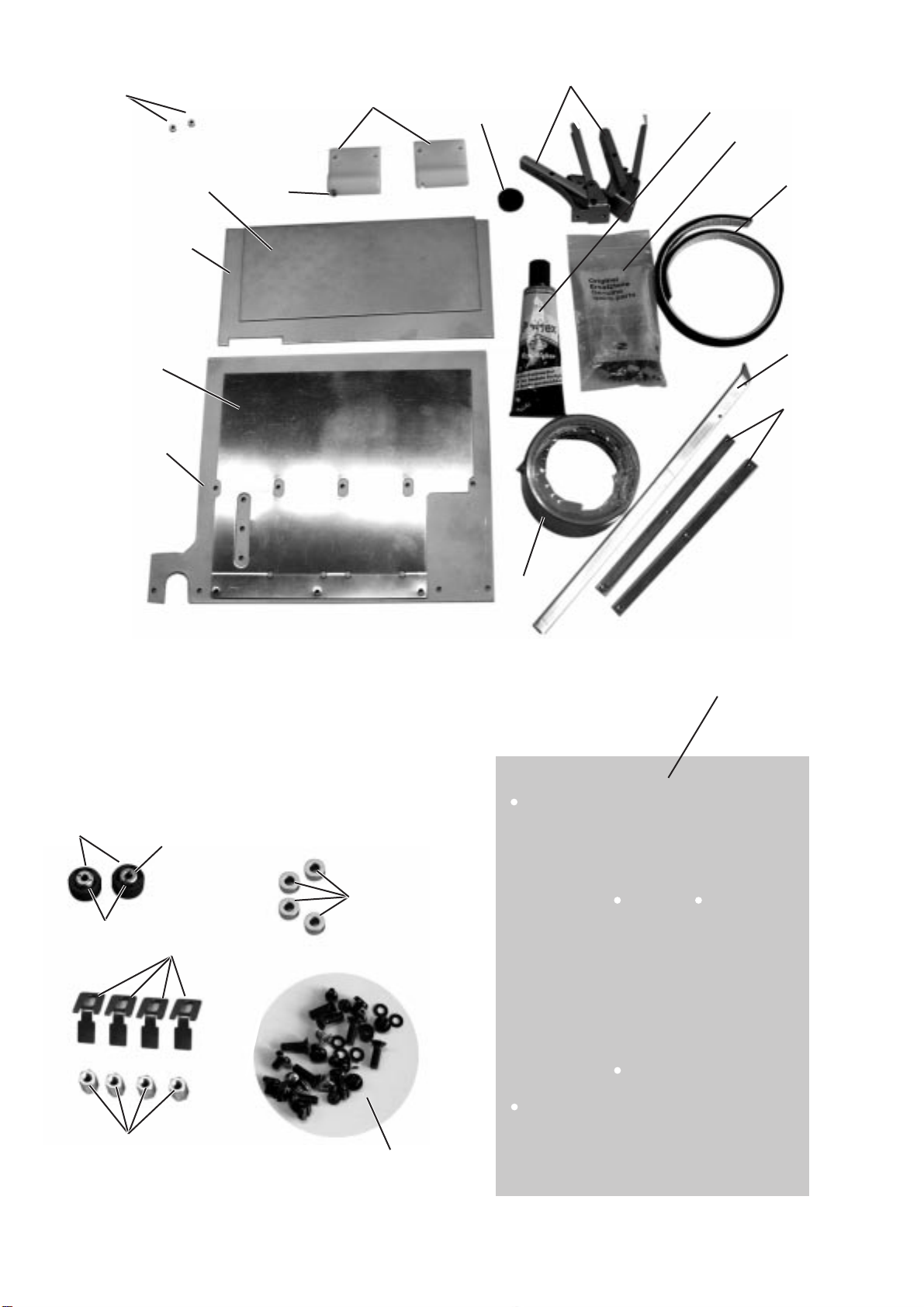
2.2 Waistband extension kit (0739 41534)
The kit contains the following parts:
Item Part No. Description
1 0739 41011 0 Bed-plate
2 0739 41012 0 Intermediate plate
3 0739 41013 0 Fullness plate
4 0739 41016 0 Clamping plate
5 9129 02303 0 Straight pin
6 0739 41001 0 Plastic holder
7 9835 90100 3 Transponder
8 0699 97392 7 Sliding foil
9 0739 410083 Foamed strip
10 Screws, nuts,
11 9049 04100 9 Adhesive
12 0739 41018 0 Long threaded shackle
13 (17,18) 0739 00505 5 Distance piece
14 0739 41009 4 Clamping element
15 0739 41015 0 Stop
washer
16 0739 41014 0 Lever
17 0739 00505 6 Push rod
18 9357 00009 0 Locking washer
19 0792 038615 Intermediate ring
20 9830 50200 5 Distance bolt
21 0797 00063 9 Shackle
(8) 0699 98914 8 Adhesive tape (double-sided)
0990 31002 3 Sanding paper
22 0739 410190 Bushing
23 0739 410200 Pointing plate
5-7
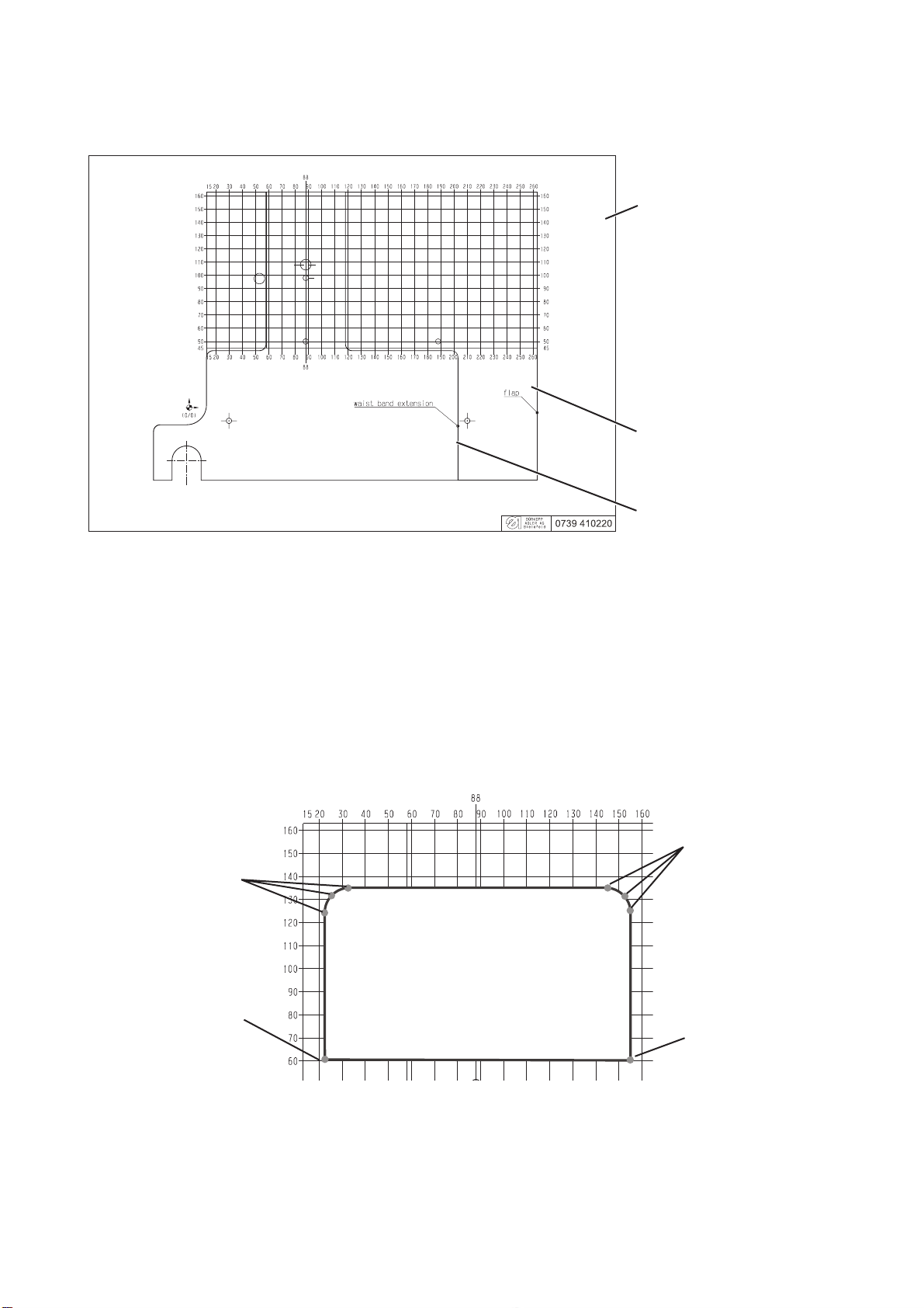
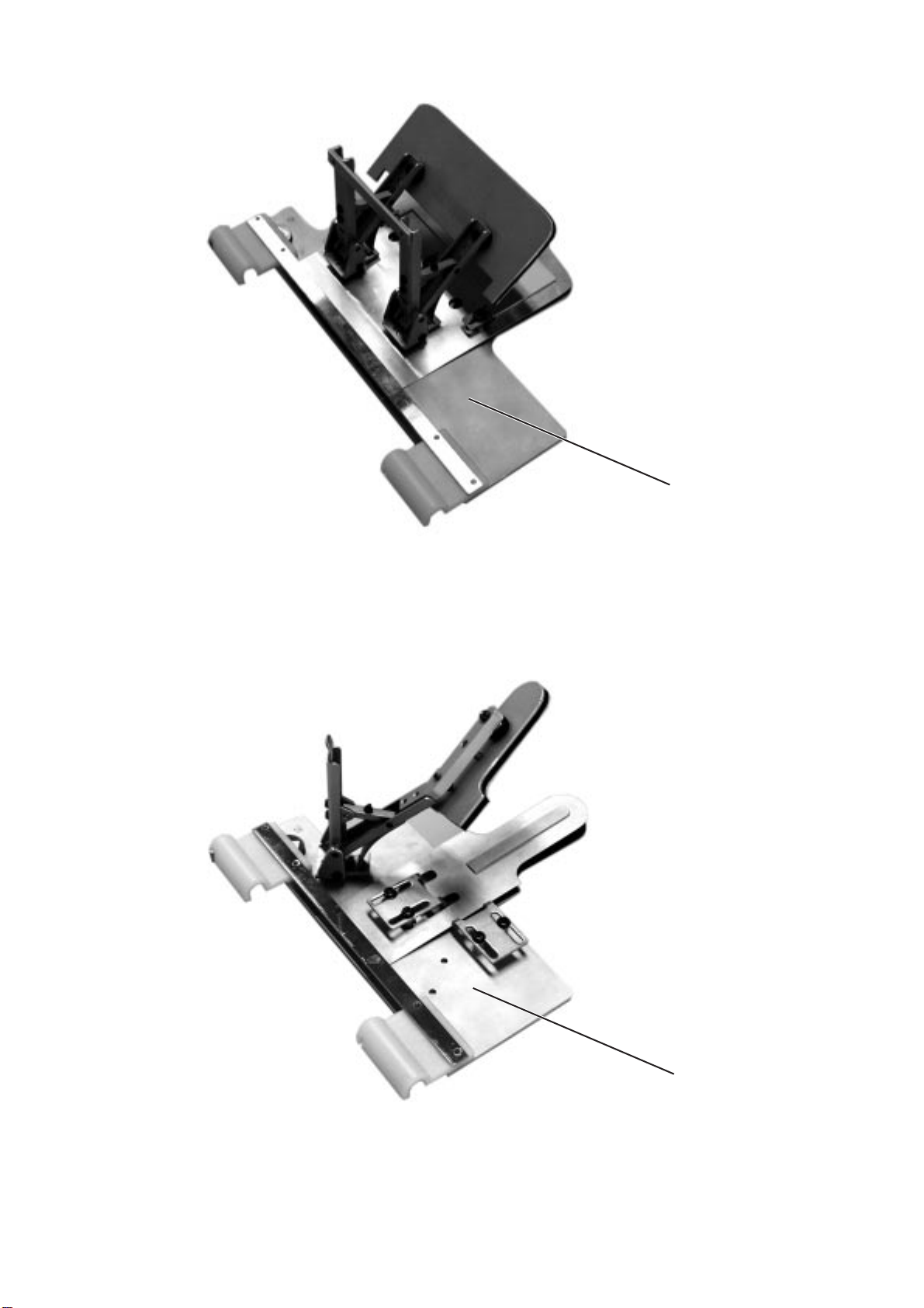
3. Manufacture of material clamps
3.1 Determination of seam coordinates
Contour template
Bed-plate for flaps
Bed-plate for
waistband extensions
Upon the setting up of the sewing programme, the exact seam contour
must be entered in the Dacs739 software. Therefore, the individual
coordinate points of the seam contour must be determined
The coordinate points are determined by means of the 0739 410220
contour TAGtemplate included in the “transponder loader” kit.
–
Position and adjust seam template on the contour template.
For adjusting of a flap template see chapter 3.1.1.
For adjusting of a waistband extension template see chapter 3.1.2.
3
2
1
4
5-8

Sewing range of diagonal flaps
CAUTION! Risk of damage!
For diagonal flaps, do not sew an angle of less than 45°.
–
Determine the coordinates for the individual points 1 to 4 and enter
the values in the Dacs739 software.
Note
In the Dacs793 “Documents” folder, sample files for frequently used
flaps and waistband extensions are saved. The sample files can be
edited for the creation of your own designs.
CAUTION!
Prior to editing, save the sample files under a different name.
Files for flaps
flap-1.dac to flap-7.dac
Files for waistband extensions
waist-band-1.dac to waist-band3.dac
5-9

3.1.1 Positioning of seam template for flaps on the contour template
12 3
–
Place flap template 3 onto the contour template.
–
Align template as follows:
Vertically (A)
The centre of flap 3 is to be positioned at the level of hole 2 for the
clamping element 4.
Horizontally (B)
Seam 1 is to run with a minimum distance of 30 mm to the left and
right of the clamping elements 4 and 5 respectively.
CAUTION! Risk of damage!
If the distance from the seam line to the clamping elements 4 and 5 is
less than 30 mm, there is a risk that the device may collide with the
suction device.
Note
Due to the minimum distance of 30 mm to the clamping elements on
both sides, the use of two clamping elements is only possible for a flap
widths of 100 mm and larger.
For flap widths < 100 mm, only one clamping element can be used.
45
5-10

3.1.2 Positioning of seam template for waistband extensions on the contour template
2
1
–
Place template 1 centred onto the “88 mm” line of the contour
template.
–
Align template vertically (A):
CAUTION! Risk of damage!
If distance a (see drawing below) is longer than 25 mm, there is a risk
of collision with the extraction unit.
Shorten lever 2 of the clamping device accordingly and define new
location hole.
Sewing contour
Material clamp contour
Edge of waistband strip
Zero point
Note
The distance of the edge of the waistband strip to the stops may vary
between 58 mm and 80 mm.
5-11

3.2 Transferring contours of material clamp to stitching plates
1
After the sewing programme has been set up by means of the Dacs739
software, contour 1 of the material clamp can be stitched to provide a
template.
Note
If the sewing programme is to be tested first, transfer the seam picture
to the stitching plate and stitch.
–
Set up sewing programme.
Thereby take into account the position of the sewing piece on the
respective bed-plate (see chapters 3.1.1 and 3.1.2).
–
Place zero gauge with transponder 1 onto the transponder loader.
The gauge is included in the delivery of the 739-23 sewing
machine.
1
1
5-12
–
Transfer seam contour by means of the Dacs739 software to the
transponder.
or
–
Draw material clamp contour.
Select “Objects > Calculate seam template” from the menu.
An line that runs parallel to the seam at a distance of 3 mm is
created.
–
Transfer template contour by means of the Dacs739 software to the
transponder.

3.3 Transfer of stitching contour to the stitching plate
21
Preparation of sewing machine
–
Remove cutting device 2 from the sewing machine.
–
Replace needle 1 with a shortened pointed needle.
–
Position pointing plate 3 on gauge 4.
–
Insert gauge in such a way that the pointing plate is positioned
below the needle.
–
Turn needle bar downwards and check the height of the shortened
needle (pointer).
The pointer must only touch the pointing plate.
–
Turn needle bar upwards.
–
Remove zero gauge.
Pointing of contour
–
Switch on sewing machine
–
Press the “OK” key.
The sewing machine is referenced.
–
Place zero gauge on the guide.
–
Press “S” key.
The stitching programme is read.
“Pointing” appears on the display.
The contour is being pointed.
43
5-13
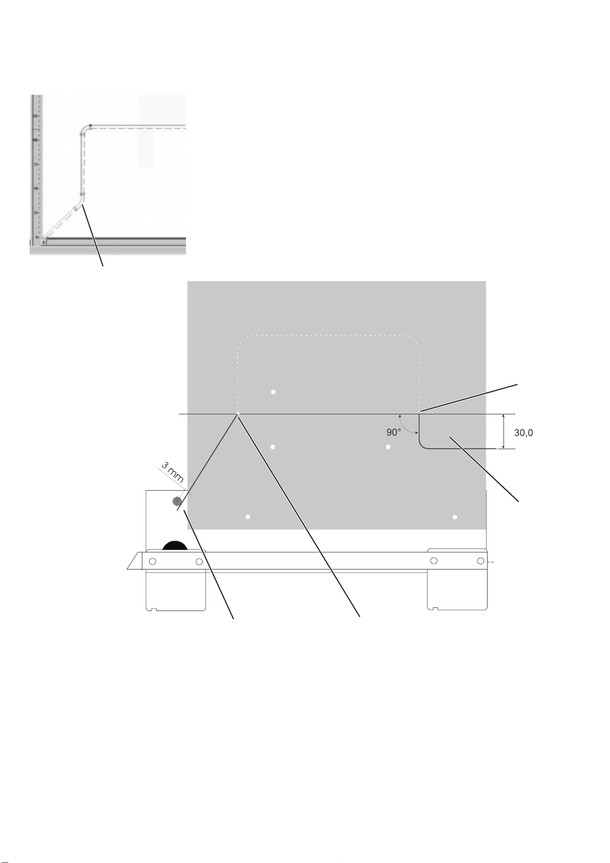
3.4 Infeed and exit of edge cutter
3.4.1 Infeed and exit of material clamps for flaps
During the referencing of the sewing machine, the edge cutter is
positioned parallel to the material clamp guide.
To ensure that there is sufficient room for it to turn at the beginning and
at the end of the seam, the bed-plate must be equipped with the
respective infeed and exit openings.
For the calculation of the equidistant by the Dacs739 programme, a
vertical line is automatically drawn from the sewing start downwards
and an additional point 1 is generated. This point 1 is the switch-on
point for the edge cutter.
1
32
Flap beginning
–
Draw a straight line from the first stitching point 2 to a point
that is 3 mm to the side of the zero point 3.
4
5
5-14
Flap end
Clearance 5 is required for the cutting and clamping of the thread.
–
Draw a vertical line of 30 mm from the last stitching point 4
downwards. Draw a horizontal line from the endpoint of this line to
the edge.
–
The two lines may also be joined by a curved line.

3.4.1 Infeed and exit of material clamps for waistband extensions
4
5
End of waistband extension
Clearance 5 is required for the cutting and clamping of the thread.
–
Draw a vertical line of 20 mm (for a radius of 10 mm) from the last
stitching point 4 downwards. Draw a horizontal line from the
endpoint of this line to the edge.
–
The two lines may also be joined by a curved line.
5-15

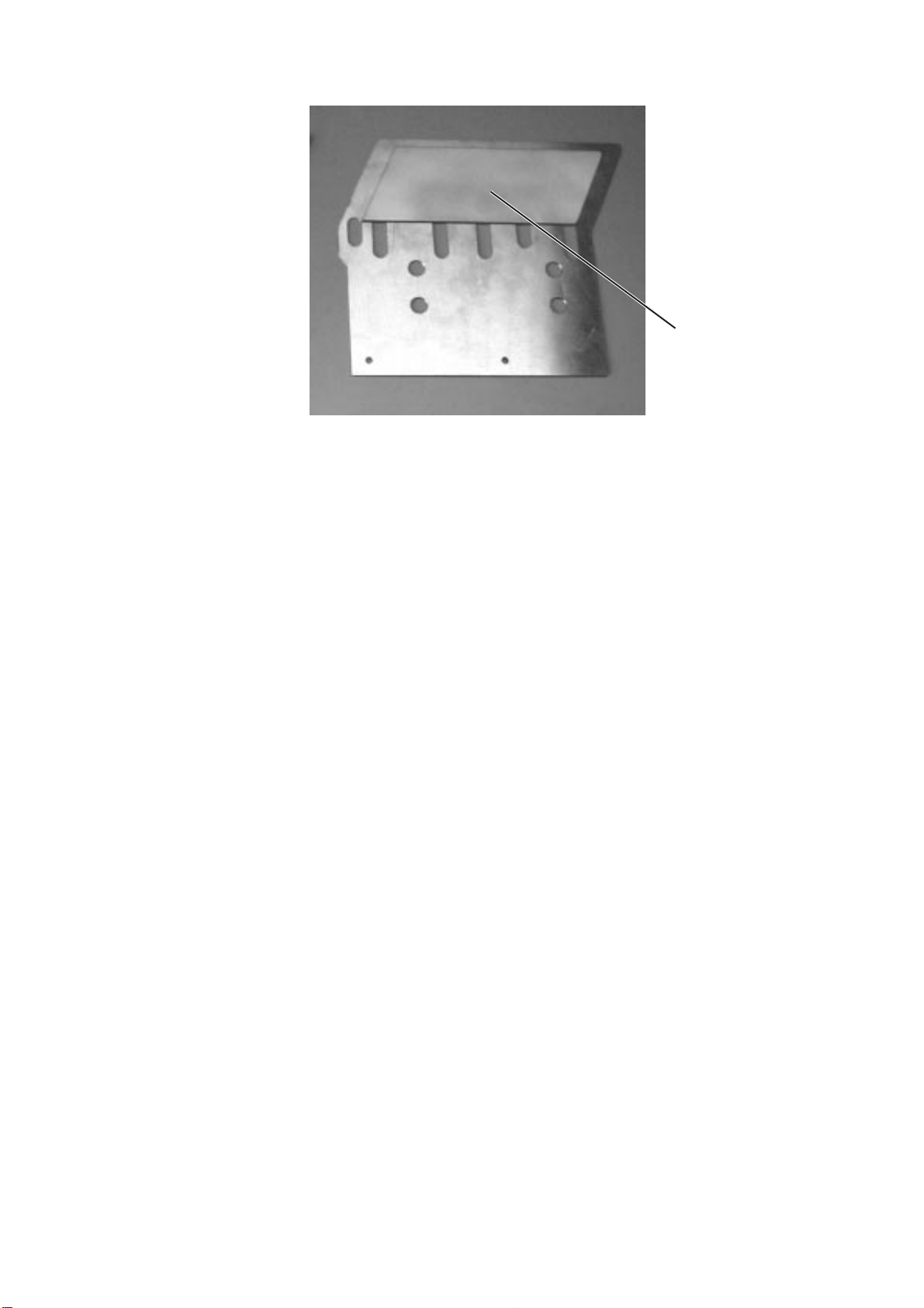
3.5 Trimming of bed-plate, intermediate sheet and clamping plate
43 21
–
Place bed-plate 4, intermediate sheet, clamping plate and pointing
plate on top of each other and secure with two countersunk screws,
washers and nuts.
For flaps, put screws through holes 1 and 3,
for waistband extensions put screws through holes 2 and 3.
Note
If the contour runs through one of the holes 1, 2 or 3, first assemble the
package and drill a new hole with a diameter of
Ø 4 mm through all four plates.
–
Cut out contour.
–
Deburr contour.
5-16
5
–
Produce edge crimp 5 of approximately 1.5 mm at the base side of
the bed-plate near the seam line.
3.6 Manufacture of fullness plates
The fullness plate 1 is also calculated by the Dacs739 software.
–
Generate fullness contour.
Select “Objects > Calculate fullness contour” from the menu.
–
Place zero gauge with transponder onto the transponder loader.
–
Transfer fullness contour by means of the Dacs739 software to the
transponder.
–
Transfer fullness contour to the stitching plate as described in
chapter 3.3.
–
Cut fullness plate to size.
–
Deburr the edges of the fullness plate.
1
5-17

3.7 Holes for clamping elements
3.7.1 Holes in material clamps for flaps
2
1
Material position
Measurements in mm
The bed-plate and the clamping plate are already equipped with
holes 1 and 2 for a clamping element.
Hole 2 should be positioned on a line going through the centre of
gravity of the material clamp contour. If the preset position does
not fulfil this requirement, new holes must be drilled.
–
Define position of clamping elements.
The length of B depends on the width of the flap.
–
Indicate holes on the bed-plate and the clamping plate (for
dimensions, see drawing).
–
Drill and deburr holes.
5-18

3.7.2 Holes in material clamps for waistband extensions
Tension lever
1
Measurements in mm
The bed-plate and the clamping plate are already equipped with holes
for the clamping element. Depending on the handling, the clamping
element can be positioned to the right or the left respectively.
If the preset holes 1 are not appropriate (collision with the suction
pipe), the tension lever can be shortened and new holes can be drilled
into the clamping plate and the tension lever.
Note:
Install tension lever to the left or right, depending on the handling.
5-19

3.8 Unlocking of clamping plate (material clamps for flaps)
Measurements in mm
1 32
For the installation of the stops 1 on a material clamp for flaps, the
clamping plate 2 has to be unlocked at the base 3.
–
Define release 3.
–
Cut out and deburr release 2.
5-20

3.9 Position of material stops
1
Material clamps for flaps can be equipped with up to 4 material stops
1, while clamps for waistband extensions can have max. two stops 2.
–
Define position of material stops.
–
Drill holes.
2
5-21

Measurements in mm
For material clamps for waistband extensions, only the position of the
material stop 3 for the width of the waistband strip must be defined.
–
Define material stop position depending on the position of the
clamping element.
–
Drill holes.
5-22
3

3.10 Slots in the intermediate plate for material clamps for flaps
1
To be able to adjust the material stops 1, the intermediate sheet must
be equipped with slots.
–
Define position of slots (see drawing).
–
Cut slots.
Measurements in mm
5-23

4. Assembly of material clamps
4.1 Bed-plate
4
4.2 Fullness plate
1
–
Adhere emery cloth onto the top surface of the bed-plate 1 in the
area of the sewing material.
Cut emery cloth to size and stick it with double-sided adhesive
tape.
–
Stick fullness plate 4 onto intermediate sheet 2
(double-sided adhesive tape).
4
2
11
2
5-24
3
–
Connect bed-plate 3, intermediate sheet 2 and threaded shackle 1
with three countersunk screws.

4.3 Adhering of foam strips to clamping plate
–
Cut foamed strip 1 to size.
–
Stick foamed strip to the inner side of clamping plate 2 (Pattex
adhesive).
1
2
4.4 Installation of tension lever
43
–
–
8
–
76 5
Secure tension lever 3 with two countersunk screws and two
distance bolts 4 from below.
Connect tension levers 5 and 7 with threaded shackle 6
(if necessary, shorten threaded shackle).
For material clamps for waistband extensions, adjust the
distribution of pressure of the clamping plate by means of the
pressure screw 8
(for inversion of pressure:
drill additional hole in clamping plate and secure tension lever 1
with cheese head screw from below).
5-25

4.5 Installation of clamping plate
3
–
4.6 Installation of material stops
2
1
21
Secure clamping plate 1 with pressure piece 2 and circlip 3 at
the tension levers.
5-26
4
4
–
Secure material stops 4 with hexagon nuts 6 and screws 5 to the
bed-plate.
5
4
6
5

4.7 Installation of holder and transponder
1
2
543
–
Insert transponder 8, pin 3 and the two bushings 6 and 9 into the
left plastic holder 4.
–
Secure both plastic holders 1 and 4 with countersunk screws and
threaded shackle 2 onto the bed-plate.
The nose 5 of the threaded shackle on the left side of the material
clamp must point to the table-top.
–
Align plastic holder 1 in longitudinal direction to the toothed belt.
The edge 7 must be flush to the bed-plate.
9876
5-27

4.8 Application of sliding foil
21
To ensure that the material clamp can be moved with minimum friction
across the table-top, a sliding foil must be adhered to the base of the
clamp.
–
Cut sliding foil 2 to size and adhere it to the base of the
bed-plate.
CAUTION!
The transponder 1 may not be covered with sliding foil.
21
5-28

 Loading...