


Contents Page:
Home
Part 2: Setting-up guide, class 69
1. Items supplied
2. General and transport packing
3. Assembling the frame
3.1 MG 5 6-2 f rame . . . . . . . . . . . . . . . . . . . . . . . . . . . . . . . 5
3.1.1 Assembling the fra me components . . . . . . . . . . . . . . . . . . . . 5
3.1.2 Assembling the table plate and mounting it on the frame . . . . . . . . 5
3.2 MG 5 3-3 f rame . . . . . . . . . . . . . . . . . . . . . . . . . . . . . . . 7
3.2.1 Assembling the fra me components . . . . . . . . . . . . . . . . . . . . 7
3.2.2 Assembling the table plate and mounting it on the frame . . . . . . . . 7
3.2 .3 Adjusting t he working height . . . . . . . . . . . . . . . . . . . . . . . . 7
4. Assembling and connecting the sewing drive
4.1 General . . . . . . . . . . . . . . . . . . . . . . . . . . . . . . . . . . . 9
4.2 Mounting the sewing drive beneath the table plate . . . . . . . . . . . 9
4.3 Connecti ng the sewing dri ve . . . . . . . . . . . . . . . . . . . . . . . . 11
4.4 Che cking the nominal voltage . . . . . . . . . . . . . . . . . . . . . . . 12
4.5 Adjusti ng the motor- protection switc h . . . . . . . . . . . . . . . . . . . 12
5. Mounting the upper part of the machine
5.1 Attaching the upper part to the table plate . . . . . . . . . . . . . . . . 13
5.2 Fitting and tensioning the V-belt . . . . . . . . . . . . . . . . . . . . . . 15
5.3 Fitting the bobbin winder . . . . . . . . . . . . . . . . . . . . . . . . . . 15
5.4 Fitting the pedal . . . . . . . . . . . . . . . . . . . . . . . . . . . . . . . 16
5.4 .1 MG 56-2 frame . . . . . . . . . . . . . . . . . . . . . . . . . . . . . . . 16
5.4 .2 MG 53-3 frame . . . . . . . . . . . . . . . . . . . . . . . . . . . . . . . 17
5.5 Potential equalisation . . . . . . . . . . . . . . . . . . . . . . . . . . . 19
5.6 Fitting the operating panel (Quick QD554/A51K01 drive unit) . . . . . 19
5.7 Fitting the knee lever . . . . . . . . . . . . . . . . . . . . . . . . . . . . 21
6. Fitting, connecting and adjusting the proximity switch
6.1 Fitting and adjusting the pro ximity sw itch . . . . . . . . . . . . . . . . . 22
6.2 Che cking the directi on of rotation . . . . . . . . . . . . . . . . . . . . . 2 3
6.3 Checking the positioni ng . . . . . . . . . . . . . . . . . . . . . . . . . . 24
6.4 Adjusti ng positions . . . . . . . . . . . . . . . . . . . . . . . . . . . . . 24
6.4 .1 Efka VD554KV/6F 62AV sewing drive . . . . . . . . . . . . . . . . . . . 25
6.4 .2 Quick QD554/A51K01 s ewing drive . . . . . . . . . . . . . . . . . . . . 26
7. Pneumatic connection
7.1 Compress ed-air maintena nce un it . . . . . . . . . . . . . . . . . . . . 29
8. Lubrication
9. Sewing test
. . . . . . . . . . . . . . . . . . . . . . . . . . . . . . . 3
. . . . . . . . . . . . . . . . . . . . . 3
. . . . . . . . . . . . . . . . . . . . . . . . . . . . . . . . . 31
. . . . . . . . . . . . . . . . . . . . . . . . . . . . . . . . . 32
6
7
1
2
3
4
5
14
8
9
10
11
12
13

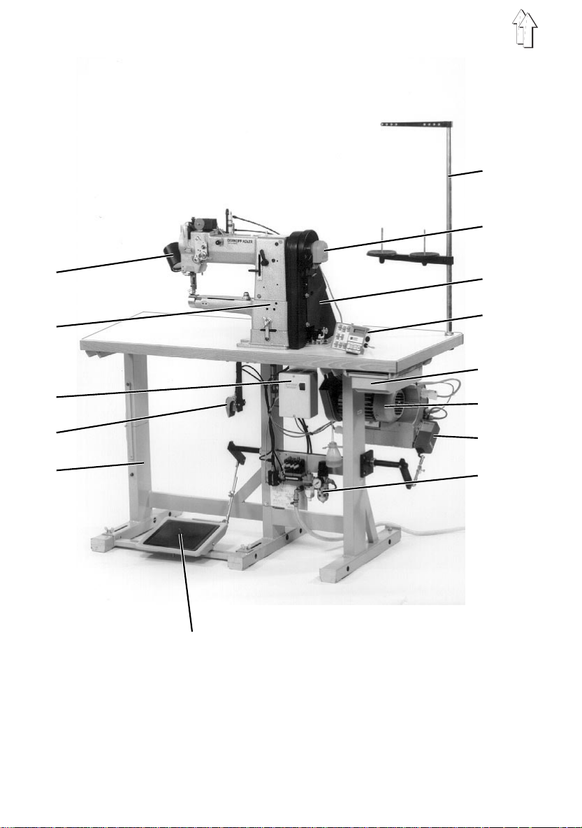
1. Items supplied
What items are supplied depends on your order.
Before setting the machine up, please check that all the required components are
present.
This description applies to sewing machines, all components of which have been
supplied by
DÜRKOPP ADLER AG
.
Basic equipment
–
upper part
2
–
motor-protection switch
3
–
frame (MG 56-2 frame illustrated) with table plate
5
–
reel stand
6
–
proximity switch (depending on drive unit)
7
–
belt guard
8
–
operating panel (depending on drive unit)
9
–
drawer
10
–
sewing drive (depending on drive unit)
11
–
desired-value transmitter (depending on drive unit)
12
–
pedal with pedal linkage
14
– belt pulley and V-belt
– minor components
Optional extras
–
lamp
1
–
knee switch (when fitted with HP 11-1)
4
–
compressed-air maintenance unit
13
(with or without thread clipper, depending on the subclass):
2. General and T ransport packi ng
CAUTION:
The special sew i ng machine may o nl y be set up by
qualified personnel.
Various drive units are a vailable for th e 69 (see also
chapter 4.1 ).
All the illustrations in this setting-up guide relate to a
special sewing m achine with the Qui ck QD554/A51K01
sewing drive.
Please note that because of the many different models
your special sewing machine may be differ ent from the
illustrations.
Transport packing
If you have pu rchased a ready-mounted speci al sewing machine, the following transport
packing must be removed:
– safety straps and battens on the upper part, table and frame
– safety blo ck and straps on the sewing drive
3
6
1
2
3
7
4
8
9
10
11
5
12
13
14
frame MG 56-2
4

3. Assembling the frame
Two frame sets are available for the 69 with different table plates:
frame table plate (W x D) version
MG 56-2
MG 53-3
1200 x 600 mm folds out separately
1060 x 550 mm 1-piece, with or without op ening
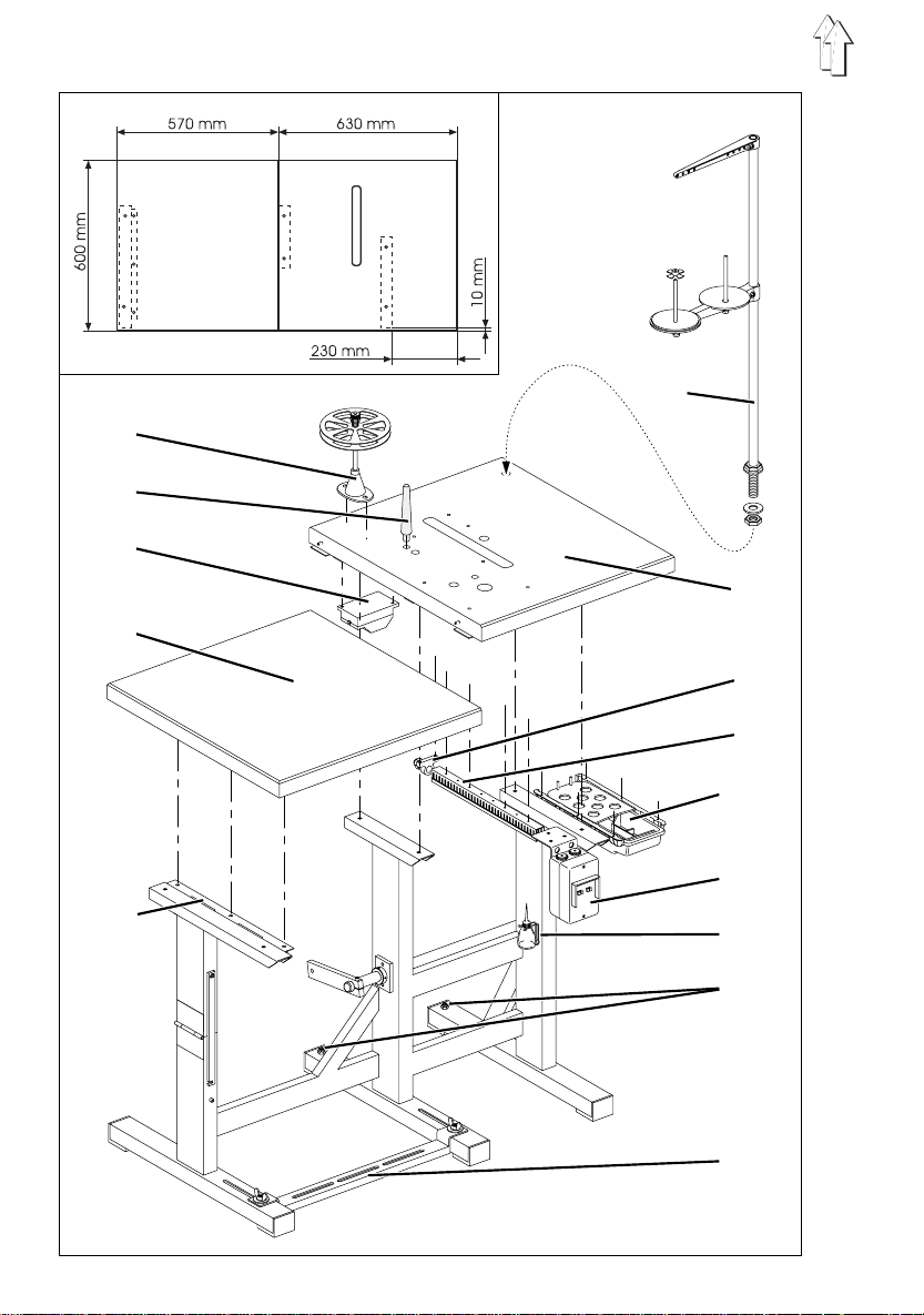
3.1 MG 56-2 frame
3.1.1 Assembling the frame components
– Fit the cross-brace 14 as shown in the illustration.
– Adjust the set screws 13 so that the frame is stable.
All six of its feet must be in firm contact with the floor.
3.1.2 Assembling the table plate and mounting it on the frame
– Hammer the support 2 into the hole in the table pla te.
This supports the upper part when it is folded back.
– Screw the drawer 10 with its mountings under the right-hand half of the table plate 7.
–Screw the
right-hand half of the table plate 7.
–Screw the
right-hand half of the table plate 7.
–Screw
the right-hand half of the table plate 7.
– Mount the
right-hand half of the table plate 7.
–Pass
9 and holder 8.
–Pass
transformer 3
– Attach the right-hand half of the table plate 7 to the frame with timber screws
(B8 x 35). Its alignment on the frame can be seen from the dimensions in the sketch.
– Attach
(B8 x 35).
– Insert
washers.
Fix and align the reel holders and unwinding arms.
The reel holders and unwinding arms must be vertically in line.
–Screw the
–Screw
ribbon binder, sewing attachment E4 or E5).
motor-protection switch 11
cable channel 9
the holder 8 for the ma i n s-lead cleat
sewing-light transformer 3
the mains cable
the connection cables of the sewing drive a nd sewing-light
from the motor-protection switch 11 through the cable channel 9.
the left-hand half of the table plate 4
the reel stand 6
oil-can holder 12
reel holder 1
behind the motor-protection switch 11 under the
of the motor -protection sw i t ch 11 through the cable channel
in the hole in the table plate and secure it with nuts and
to the right-hand frame upright.
to the right-hand half of th e table plate 7 (o nl y when fitted wit h
with its attachment bracket underneath the
behind the cab l e channel 9 under
(optional ex t ra) at the back under the
to the hinge 5 with timber screws
5
8
1
2
9
3
4
10
11
5
12
6
7
13
14
6
MG 53-3 frame

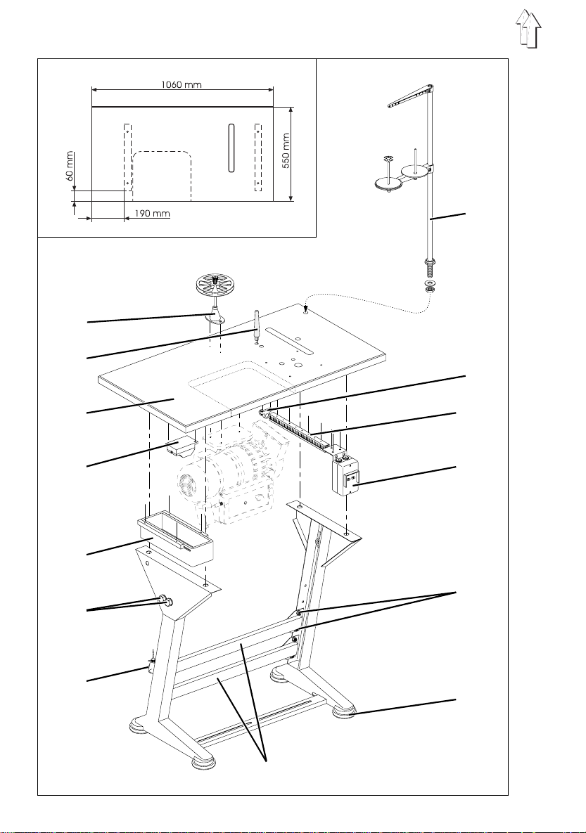
3.2 MG 53-3 frame
3.2.1 Assembling the frame components
– Assemble the frame components as shown in the illustration.
– Fit the four frame feet 13.
– Slightly un do the screws 12 on both sides of the cross-braces 14 and ensure that
the frame is stable.
All four of its feet must be in firm contact with the floor.
3.2.2 Assembling the table plate and mounting it on the frame
– Hammer the support 2 into the hole in the table pla te 3.
This supports the upper part when it is folded back
–Screw the
–Screw the
plate 3.
–Screw the
plate 3.
–Screw the
the table plate 3.
–Screw the
– Pass the
channel 10 and holder 9.
– Pass the
transformer 4
– Attach
Its alignme nt on the frame can be seen from t he dimensions i n the sketch.
– Insert
washers.
Fix and align the reel holders and unwinding arms.
The reel holders and unwinding arms must be vertically in line.
–Screw the
–Screw
sewing atta chment E4 or E5).
wooden drawer 5
motor-protection switch 11
cable channel 10
holder 9 for the mains- l ead cleat
sewing-light transformer 4
mains cable
connection cable of the sewing drive and the sewing-light
from the motor-protection switch 11 through the cable channel 10.
table plate 3
the reel stand 8
oil-can holder 7
reel holder 1
to the frame with timber screws (B8 x 35).
to the table plate 3 (only when fitted with ribbon binder,
with its guides on the left under the table pla te 3.
with its attachment bracket under the table
behind the motor-protectio n switch 11 under the table
behind the cable channel 10 under
(optional extra) under the table plate 3.
from the motor-protection switch 11 through the cable
in the hole in the table plate 3 and secure it with nuts and
to the left-hand frame upright.
3.2.3 Adjusting the working height
The working height is adjustable between 750 and 840 mm (measured to the upper
edge of the ta bl e plate).
– Undo screws 6 on both frame uprights.
– Adjust table plate 3 to the desired working height and ensure it is level.
To avoid tilting pull the table plate 3 out or push it in equally at each side.
– Tighten screws 6.
7
1 2
5
6
MG 56-2 frame
7
1
2
3
4
6
MG 53-3 frame
8

4. Assembling and connecting the sewing drive
4.1 General
Drive units
Complete driv e units are availab l e for the 69.
The drive unit depends on what attachments are fitted to the special sewing machine.
The following table shows which drive unit is required depending on the subclass and
optional extr as.
subclass sewing drive operating panel optional extra
FLP 1 4-2 R AP 14-1 HP 11- 1
69-373
69-FA-373
Components of all drive units:
– sewing drive
– pedal linkage
– V-belt pulley (Ø = 112 mm)
–V-belt
– installati on plan
– attachment and connection material
Extra components for FIR 1147-F-554.3 drive unit:
– mains switc h with attachme nt material and connection leads
Extra components for Efka VD554KV/6F62AV and Quick QD554/A51K01 drive units:
– holder for proximity switch
– earth lead
– motor-protection switc h (2,5 - 4,0 A) with at tachment material and connecti on leads
– AB4 operating panel (only for Quick QD554/A51K01)
FIR1147-F-554.3 Efka VD554KV/6F 62AV - X
Quick QD554/A51K01 AB4 X X
Quick QD554/A51K01 AB4 X X X
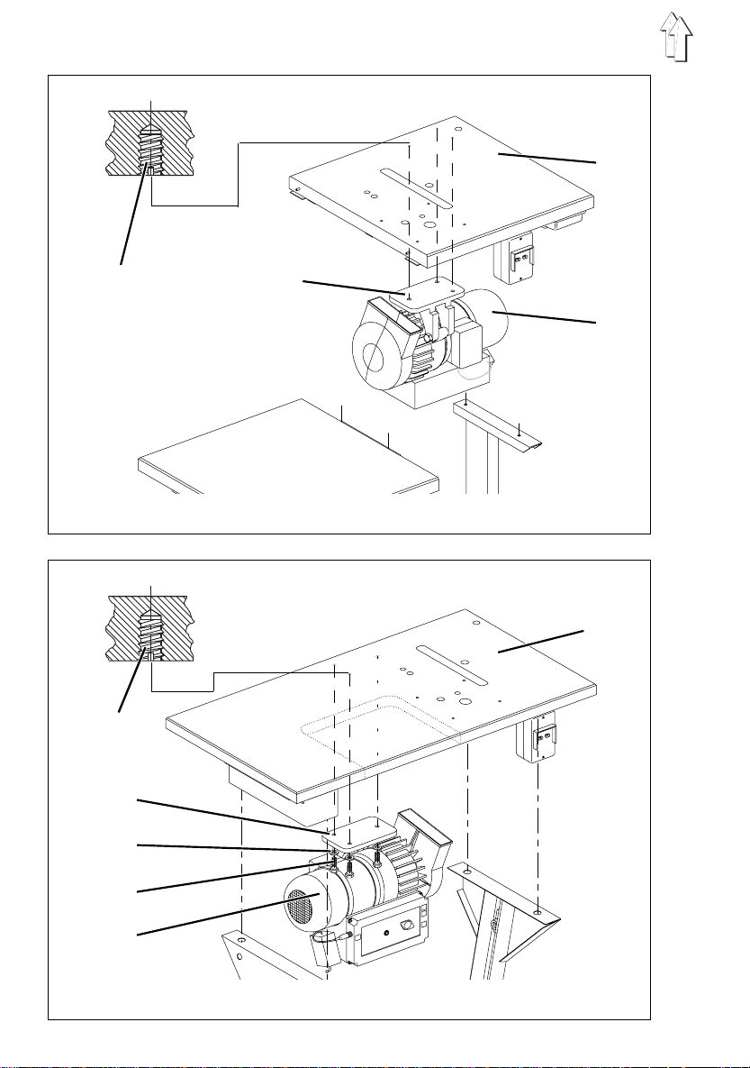
4.2 Mounting the sewing drive beneath the table plate
– Attach sewing drive 6 (Quick in the illustration) with its base 2 to the underside of
the table plate 7 or right-hand half of the table plate 5 (MG 5 6-2 frame).
Screw in the three hexagonal screws 4 (M8 x 35) with washers 3 into the nuts 1 of
the table plate.
9
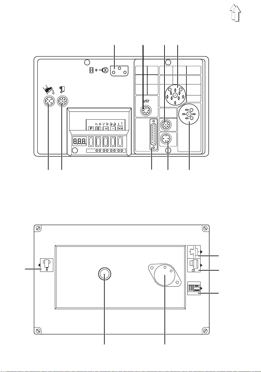
Efka VD554KV/6F82AV connection sockets:
B2 B 18 B4 B3
B80 B1 B776 B12 B5
Quick QD554/A51K01 connection sockets:
1
10
2
3
4
5 6

4.3 Connecting the sewing drive
CAUTION:
All work on the electrical equipment of this special sewing
machine may o nl y be carried out by qualified e l ectricians or
other appropri ately trained p ersons.
The mains plug must be removed.
It is essential to comply with the manufacturer’s
operating instructions (supplied).
All sewing drives (FIR, Efka, Quick):
– Connect the electrical connection lead from the main switch to the sewing drive.
Efka VD554KV/6F82AV sewing drive:
– Plug the connection cable of the clutch/brake into socket B2 of the control box.
– Plug the connection cable of the desired-value transmitter (pedal) into socket
of the control box.
connection sockets:
- proximity switch
B1
- clutch / brake of the sewing drive
B2
- upper part of machine
B3
- keypad
B4
- upper part of machine
B5
- keypad
B12
- light barrier
B18
- desired-va l ue transmitte r (pedal)
B80
- operating p anel
B776
B80
Quick QD554/A51K01 sewing drive:
– Plug the connection cable of the clutch/brake into socket 2 of the control box.
– Plug the connection cable of the desired-value transmitter (pedal) into socket 1 of
the control box.
connection sockets:
- desired-va l ue transmitte r (pedal)
1
- clutch/brake of the sewing drive
2
- proximity switch
3
- operating p anel
4
- knee switch
5
- upper part of machine
6
11

4.4 Checking the nominal voltage
CAUTION:
The mains vol t age must coincide with the rated voltage
specified on the model-ident i fication plate.
The unit is ad apted to the lo cal mains supply vi a the connecti on terminals of the
sewing-driv e transformer.
– Check the arrangement of the connections on the sewing-drive transformer.
– If necessary, change the connections in accordance with the mains voltage (see
circuit diagram).
4.5 Adjusting the motor-protection switch
With the
motor-protection switch on the induction regulator 1 must be set in accordance with the
mains voltage:
Efka VD554KV/6F82AV
3 x 220-240 V, 50/60 Hz: 4 A
3 x 380-415 V, 50/60 Hz: 2.5 A
and
Quick QD554/A51K01
sewing drives the
1
12

5. Fitting the upper part
5.1 Attaching the upper part to the table plate
1
2
3
4
Attaching the upper part to the table plate
– Attach the upper-part base 3 to the tabl e plate with th e four screws 4 (M 6X60),
washers and nuts.
Turning the upper part back
– Undo wing-nut 1.
– Swivel hook 2 to the left.
The upper part is released.
– Turn the upper part back and lay it on the supp ort.
13

1 2
7
3 4 5 6
3 9
10 11
14
8
3 4 5
12 6

5.2 Fitting and tensioning the V-belt
Removing the protective devices
– Remove the two-part belt guard 1 and 2 on the upper part.
The attachment screws are accessible through the holes in both parts of the belt
guard.
– Remove the belt guard 10 on the sewing drive 9.
Fitting the V-belt and belt guard
– Attach the belt pulley (supplied) to the sewing-drive shaft 9.
– Place the V-belt 3 on the belt pull ey on the upper p art.
– Pass the V-belt 3 down through the opening in the table plate.
– Turn the upper pa rt back.
– Place the V-belt 3 on t he belt pulley of t he sewing drive 9.
– Turn the upper pa rt forward again.
– Fit the two-part belt guard 1 and 2 to the upper part.
– Screw on the anti-twist device 8 for the proximity switch 7 (
and
Quick QD554/A51K01
Tensioning the V-belt
– Undo screw 11 on the base of the sewing drive 9.
– Tension the V-belt 3 by swivelling the sewing-drive 9.
When the belt is correctly tensioned It must be possible to depress it by about 10
mm by gently pressing on it with a finger at its mid-point.
–Tighten screw 11.
Fitting the belt guard to the sewing drive
– Adjust the run-off protectors (adjustable cams or joints, depending on the drive
type) of the belt guard 10 as fo l l ows:
With the upper part turned back the V-belt 3 must remain in contact with the belt
pulleys.
– Fit the belt guard 10 to the sewing drive 9.
(if they are fitted when the machine is delivered)
Efka VD554KV/6F62AV
drive units only).
5.3 Fitting the bobbin winder
The V-belt 3 drives the bobbin winder via the bobbin-winder wheel 4.
– Swivel the bobbin-winder l ever 5 against t he bobbin.
– Attach the bottom of the bobbin winder 6 to the table plate with two timber screws.
Use the slots 12 to align the bottom of the bobbin winder 6 as follows:
The bobbin-w i n der wheel 4 must be in contact w i t h t he V-belt 3 under very sli ght
pressure.
– Turn the handwhe el .
The bobbin-winder wheel 4 must turn with it.
15

5.4 Fitting the pedal
5.4.1 MG 56-2 frame
3
1 2
5
6
7
8
4
10 11
– Attach the pedal 10 to frame strut 11.
There is a slot in frame strut 11 for this purpose.
– Fit pedal l i nkage 3 to the pedal 10 and att a ch lever 1.
– Attach the linkage 6 to lever 7 and the desired-value transmitter 5 of the sewing
drive.
– Undo the threaded pins on b ot h adjustment rings 2.
– Undo locki n g screws on lever s 1 and 7.
– Align the shaft 8 axially with levers 1 and 7.
Linkages 3 and 6 must be vertical when seen from the operating side.
– To fix the shaft 8 push the adjustment rings 2 up against t he bearing plat es 9.
– Tighten locking screws on levers 1 and 7.
– Slightly undo screw 4.
– Adjust the height of pedal l i nkage 3 as follows:
When not under pressure the peda l 10 must be at an in cl i nation of about 10°.
– Tighten screw 4.
9
16

5.4.2 MG 53-3 frame
1
2
3
4 5
– Attach pedal 4 to the frame strut 5.
There is a slot in frame strut 5 for this purpose.
– Attach pedal linkage 2 to the pedal 4 and desired-value transmitter 1 of the sewing
drive.
– Slightly un do screw 3.
– Adjust the height of pedal linkage 2 as follows:
When not unde r pressure the ped al 4 must be at an incl i nation of abou t 10°.
– Tighten screw 3.
17

1
2
3
4
5
18
6 7 8

5.5 Potential equalisation
On the
Efka VD554KV/6F62AV
3 conducts static charges from t he upper part 1 via the sewing drive 5 to earth.
– Attach the cable lug of the earthing lead 3 to the base 4 of the sewing drive 5 with
screw (M4) and washer.
A threaded hole is provided in the ba se 4 for this pur pose.
– Pass the earthing lead 3 up through the hole in the table plate.
– Attach the earthing lead 3 to the base 2 of the upper part with receptacle, tab,
antiturn washer and screw (M 4).
A threaded hole is provided in the ba se 2 for this pur pose.
and
Quick QD554/A51K01
drive units the earthing lead
5.6 Fitting the operating panel (Quick QD554/A51K01 drive unit)
– Attach external operating p anel 7 to the tabl e plate with att achment bracket 6 and
timber screws.
– Pass connection lead 8 down through the hole in the table plate.
– Insert the plug of the co nnection lead 8 i nto the socket 4 of the drive-co ntrol unit
(see illustration on page 10).
19

1
5
6
7
8
9
2
10
11
3
12
13
4
14
7 9 10
2
8
3
13
12
11
20
4

5.7 Fitting the knee lever
The sewing feet are mechanically raised with the knee lever 4.
The movement of the knee lever is transmitted to the lifting lever 1 via the chain 6 and
tension bar 5.
– Attach the shaft 10 with both supports 2 and 13 and 4.5 x 20 timber screws
beneath the table plate.
– Place stop cams 8 and 12 against supports 2 and 13.
– The stop cam s 8 and 12 limit the movement o f the knee lever 4 i n both directions.
Turn the stop cams on the shaft 10 accordingly and tighten the locking screws.
– Attach chain 6 with hook 7 to the pressure bar 3.
– Move the adjustment block 9 along shaft 10 and tighten the locking screw.
The chain 6 must pass vertically down through the hole in the table plate.
– Move the block 11 along shaft 10 and tighten the locking screw.
The knee lever 4 must be easy for t he operator to us e i n a normal sitting position.
– Undo locking screw 14.
– Adjust the height of knee lever 4.
– Tighten locking screw 14.
21

6. Fitting, connecting and adjusting the proximity switch
2
1
3
4
5
6.1 Fitting and adjusting the proximit y switch
– Place the proximity switch 3 (Quick in the illustration) on the handwheel flange.
The groove in the proximity-switch housing must engage with the belt guard via the
antitwist device 4.
– Tighten both threaded pins 1 on the proximity-switch ring 2.
– Pass the con nection lead 5 dow n through the hole in the table plate.
– Insert the plug of connection lead 5 in the appropriate socke t of the drive-co ntrol
unit (see illustrations on page 10).
22

6.2 Checking the direction of rotation
CAUTION:
Before the special sewing machine is started it is essential
to check the direction of rotation of the motor.
Switching it on can cause damage if the direction of
rotation is incorrect.
The sewing drives are fitted t o the frames in t wo different
positions.
The direction of rotation of the sewing drive depends
on which frame is used.
MG 53-3 frame: MG 56-2 frame
left rotation right rotation
:
1
frame direction of sewing-drive rotati on
MG 53-3
MG 56-2
In the three-phase sewing drives used it is the rotating field of the supply voltage which
determines the direction of rotation.
– Insert the mains plug.
– Check the direction of rotation of the motor fan (behind the fan grille 1) by briefly
turning on the main switch. The arrows in the above illustration show the correct
direction of rotation for the two frame types.
– If the direction of rotation is wrong, two phases in the mains plug must be swapped
over.
(looking at the belt pulley)
left rotation (anticlockwise)
right rotation (clockwise)
CAUTION:
If the direction of rotation has been changed the positions
must be reset or re-programm ed.
23

6.3 Checking the positioning
– Turn on the main switch.
– Move the pedal briefly forwards.
The sewing machine assumes
dead centre). Check the pos i tion of the nee dl e.
CAUTION
Subclass
edge, eye of the needle and the surface of the needle plate are all at the same
level.
– Move the pedal fully back and hold it there.
On machines with a thread clipper the thread is severed.
The sewing machine assumes
thread leve r, i.e. the tension in the thread shou l d j ust have been released).
– Check whet her the thread l ever is just behi nd its top dead centre.
To do this, turn the handwheel a few degrees in both directions.
– This is normally all the checking which is necessary.
Should any adjustment to the works settings be necessary, proceed as follows.
assumes a position such that after top dead centre the upper
69 FA
position 1
position 2
(loop-stroke position, i.e. 2 mm after top
(just behind t he highest positi on of the
6.4 Adjusting positions
The proximity switch must be re-adjusted after the following work has been carried out:
– fitting the proximity switch when setting up the special sewing machine
– unscrewing the proximit y switch
– replacing the proximity switch
– replacing the microprocessor of the dri ve-control unit
– replacing the entire drive -c ontrol unit
24
1 2 3
4

6.4.1 Efka VD554KV/6F62AV sewing drive
Caution: danger of injury
Turn off the main switch before adjusting positioning
pulleys 1 and 4.
The utmost care must be taken when adjusting the
positioning pulleys. The positioning pulleys and the
generator (innermost) pul ley must not be damaged.
The position of positioning pulleys 1 and 4 determines the machine positions.
Position 1
–Use the ">>" button on the control box to select the basic "
position(the left-hand LED beneath the button lights up).
– Move the pedal briefly fo rwards.
The sewing machi ne stops in the 1s t position.
– Check whether the needle is in the loop-stroke position (2 mm after bottom dead
centre).
CAUTION:
Subclass
edge, eye of t he needle and th e surface of the ne edle plate are al l at the same
level.
– Turn off the mai n switch.
– Remove cover 3 after undoi ng the attachm ent screw.
– Slightly undo locking screw 2.
– Turn the middle positioning pul ley 4 for position 1 in the des i red direction.
assumes a posi tion such that af ter bottom de ad centre the up per
69 FA
needle down
"
Position 2 (thread lever just behind top dead centre)
– Turn on the main swi tch.
–Use the ">>" button on the control box to select the basic "
right -hand LED beneath the button light s up).
– Move the pedal briefly fo rwards.
The sewing machi ne stops in the 2nd position.
– Check whether the thread l ever is just behi nd top dead cent re.
The tension in t he thread shoul d j ust have been rel eased.
– Turn off the mai n switch.
– Turn the outer positioning pulley 1 for position 2 i n the desired direction.
– Turn on the main swi tch.
– Check the 1st and 2nd positions again.
Repeat the process if necessary.
– Tighten locking screw 2.
– Replace cover 3.
CAUTION:
After the direction of rot at ion has been ch anged the
positions must be reset.
needle up
" position(the
25

6.4.2 Quick QD554 / A51K01 sewing drive
No mechanical adjustment to the digital proximity switch is required.
Only the reference position must be set prior to the machine’s first use.
The machine positions are registered by the proximity switch in steps (increments) and
displayed.
One revolution of the handwhe el i s equivalent to 480 steps. The display is updated
every 2 steps. A change from one displayed value to the next thus corresponds to an
angle of rotation of about 1.5°.
The angle of positions 1 and 2 to the reference position is defined in each case by a
fixed number of increments.
Reference position
The reference position is start i ng point for all pre-set positio ns.
In the reference position the needle is just entering the needle plate.
The tip of the needle is on a level with the upper side of the needle plate.
Position 1
In the 1st position the needle must be in the loop-stroke position, i.e. 2 mm after bottom
dead centre.
On machines with thread clipper s t he severing process is initiated in the 1st position.
Subclass
eye of the needle and the surf ace of the needle plate are all at the same level.
position 2
In the 2nd position the thread lever must be just behind its upper dead centre.
Programming steps:
1. Selecting programming mode
-
Turn off the main switch.
-
Simultaneousl y press and hold down the "G" and "-" buttons.
-
Turn on the main switch again.
The control unit switches to t echnician level .
"
*MANUAL
assumes a posi tion such that af ter bottom de ad centre the up per edge,
69 FA
" appears in the display.
2. Programming the reference position
-
Simultaneousl y press the "G" and "-" buttons.
-
Release both buttons.
"
-
Press the "G" button repeatedly until "
-
Press the "F" button.
"
"
is screwed on.
-
Move pedal briefly forwards.
The upper part takes up any position.
-
Turn the handwheel to move the upper part to the reference position (needle tip
on the upper edge of the needle plate).
Caution:
For all settings the
rotation.
" appears in the display.
ENTER
G7******
700*XXXX
XXXX
" appears in t h e display.
" stands for the number value of the position at which the proximity switch
handwheel must be turned in the machine’s direction of
" appears in t h e display.
26

-
Move pedal briefly forwards.
The programmed reference position is saved.
-
Simultaneously press the "G" and "-" buttons.
"
*MANUAL
3. Programming position 1
-
Simultaneously press the "G" and "-" buttons.
-
Release both buttons.
"
ENTER
-
Press the "F" button.
appears in the display "
-
Press the "F" button repe at edly until "
-
Move pedal briefly forwards.
The upper part moves to pre-set position 1.
-
Turn the handwh eel until the 1st position (loo p-stroke posit i on) is reached.
CAUTION:
Subclass
edge, eye of the needle and the surface of the needle plate are all at the same
level.
-
Move pedal briefly forwards.
The programmed 1st position i s saved.
4. Programming position 2
-
Press the "F" button.
"
703*XXXX
-
Move pedal briefly forwards.
The upper part moves to pre-set position 2.
-
Turn handwheel un til the 2nd posit i on (thread lever j ust behind its top dead
centre) is reached.
-
Move pedal briefly forwards.
The programmed 2nd position is sav ed.
" appears in t h e display.
" appears in t h e display.
700*XXXX
assumes a position such that after bottom dead centre the upper
69 FA
" appears in the display.
".
702*XXXX
" appears in the display.
5. Leaving programming mode
-
Simultaneously press the "G" and "-" buttons.
"
*MANUAL
-
The sewing machi ne is ready for operation.
" appears in t h e display.
27

2
3
1
1
4
5
6
4
8
2
10
6
1
28

7. Pneumatic connection
The pneumatic optional extras require a supply of m oisture-free compressed air.
CAUTION:
The pneumatic assemblies will only function properly at a
mains pressure of 8 to 10 bar.
The operating pressure of the special sewing machi ne is
.
6 bar
– Connect the special sewing machine to the local compressed-air supply with
connection hose 1 (Ø = 9 mm).
–
Pneumatic connection kit
A pneumatic connection kit is available for frames with a compressed-air
maintenance unit and pneumat i c optional extras under order no. 0797 003031.
It contains the following components: - connection hose, 5m long , Ø = 9 mm
7.1 Compressed-air maintenance unit
The WE-6 compressed-air maintenance unit for pneumatic opt i onal extras is av ailable
under order no . 9781 000002.
Connecting the compressed-air maintenance unit
– Attach the compressed-air maintenance unit 4 with bracket 3 and plate 2 to the
frame.
– Connect the compressed-air maintenance unit 4 with connection hose 1 (Ø = 9
mm) and R1/4" hose connec tor to the local compressed-air supply.
- hose connectors and ties
- connector plug and sock et
Adjusting the operating pressure
The operating pressure is
It can be read off at the pressure gauge 6.
– To adjust the operating pressure, lift and turn rotary handle 5.
to increase pressure: turn rotary handle 5 clockwise
to decrease pressure: turn rotary handle 5 anticlockwise
6 bar
.
29

1 2 3 4 5 6 7 8
9 10 11
30

8. Lubrication
Caution: danger of injury
Oil can cause skin eruptions.
Avoid protracted contact with t he skin.
In the event o f contact, thorou ghly wash the affect ed area.
CAUTION:
The handling an d disposal of mine ral oils is subject to legal
regulation.
Deliver used oil to an authorised collection point.
Protect your environment.
Take care not to spill oil.
To lubricate the special sewing machine use only
ESSO SP-NK 1 0
or an equivalent oil of the fol l owing specificati on:
– viscosity a t 40° C : 10 mm
– flashpoint: 150 °C
lubricating oil
2
/s
ESSO SP-NK 1 0
following part numbers:
2-litre container: 9047 000013
5-litre container: 9047 000014
Oiling lubrication points
– Remove top, cap, needle plate and lower part of needle plate.
– Us a cloth to clean all visible parts of rust-i nhibiting grease and dirt.
– Oil lubrication points 1-17 shown in the illustration with a few drops of oil.
NB:
Subclass
– Replace top , lower part of needle plate, needle plate and cap.
is available from
69-FA-373
has no lubrication point 8.
DÜRKOPP AD LER AG
retail outlets under the
12 13 1 4 15 16 1 7
31

9. Sewing test
A sewing test must be carried out on completion of the setting-up process.
– Insert the mains plug.
Caution: danger of injury
Turn off the main switch.
The looper thr ead may only be threaded for windi ng on
with the sewing machine switched off.
– Thread the looper thread for winding on (see operating instructions).
– Lock the sewing feet in the raised position (see operating instructions).
– Turn on the main switch.
– Fill the bobbin at low sewing speed.
Caution: danger of injury
Turn off the main switch.
The needle and l ooper threads m ay only be threaded wi t h
the sewing machine switched off.
– Thread the needle and looper threads (see operating instructions).
– Select the material to be pr ocessed.
– Carry out a s ewing test, first at low speed and t hen at gradually increasing spee d.
– Check that the seams are of the required quality.
If not, alter the thread ten sions (see operating instructions).
If necessary the settings gi ven in the servic i ng instructions should be check e d and
adjusted.
32
 Loading...