


Contents Page:
Home
Preface and general safety instructions
Part 1: class 69 operating instructions
1. Product description
2. Designated use
3. Subclasses
3.1 Opt ional extras . . . . . . . . . . . . . . . . . . . . . . . . . . . . . . . 6
4. Technical data
5. Operation
5.1 Folding down left-hand half of table plate (MG 56-2 frame only) . . . . 9
5.2 Threading the needle thread . . . . . . . . . . . . . . . . . . . . . . . . 10
5.2. 1 Subclass 69-373 . . . . . . . . . . . . . . . . . . . . . . . . . . . . . . 10
5.2. 2 Subclass 69-FA-373 . . . . . . . . . . . . . . . . . . . . . . . . . . . . 11
5.3 Adjusting t he n eedle-t hread tensi on . . . . . . . . . . . . . . . . . . . 13
5.4 Opening the nee dle-thread ten sioner . . . . . . . . . . . . . . . . . . . 13
5.5 Winding on the loop er thread . . . . . . . . . . . . . . . . . . . . . . . 15
5.6 Fitting the looper-th read bob bin . . . . . . . . . . . . . . . . . . . . . . 15
5.7 Adjusting the looper-thr ead t ension . . . . . . . . . . . . . . . . . . . . 17
5.8 Fitting and cha nging the needl e . . . . . . . . . . . . . . . . . . . . . . 17
5.9 Lifting the sew ing feet . . . . . . . . . . . . . . . . . . . . . . . . . . . 19
5.1 0 Loc king the sewing feet in the raised position . . . . . . . . . . . . . . 19
5.11 Adjusting the sewing-foot str oke . . . . . . . . . . . . . . . . . . . . . 19
5.12 Adjusti ng th e sewing-foot pressure . . . . . . . . . . . . . . . . . . . . 20
5.1 3 Adjusting t he stitch le ngth . . . . . . . . . . . . . . . . . . . . . . . . . 20
5.1 4 Welting . . . . . . . . . . . . . . . . . . . . . . . . . . . . . . . . . . . 21
5.1 5 Ribbon binder (class 69-373) . . . . . . . . . . . . . . . . . . . . . . . 22
. . . . . . . . . . . . . . . . . . . . . . . . . . . . 5
. . . . . . . . . . . . . . . . . . . . . . . . . . . . . . 5
. . . . . . . . . . . . . . . . . . . . . . . . . . . . . . . 6
6. Control unit and operating panel
6.1 General . . . . . . . . . . . . . . . . . . . . . . . . . . . . . . . . . . . 2 3
6.2 Efka VD5 54KV/6F82AV sewing drive . . . . . . . . . . . . . . . . . . . 24
6.2 .1 Control-b ox buttons . . . . . . . . . . . . . . . . . . . . . . . . . . . . 24
6.2 .2 Altering parameter values . . . . . . . . . . . . . . . . . . . . . . . . . 26
6.3 Qui ck QD554/A51 K01 sewi ng drive . . . . . . . . . . . . . . . . . . . . 28
6.3 .1 Operat ing-panel b utt ons . . . . . . . . . . . . . . . . . . . . . . . . . . 28
6.3 .2 Altering parameter values . . . . . . . . . . . . . . . . . . . . . . . . . 30

Contents Page:
7. Sewing . . . . . . . . . . . . . . . . . . . . . . . . . . . . . . . . . . . 32
8. Maintenance
8.1 Cleaning and test ing . . . . . . . . . . . . . . . . . . . . . . . . . . . 34
8.2 Lubrication . . . . . . . . . . . . . . . . . . . . . . . . . . . . . . . . . 37
9. Optional extra s
9.1 HP 11-1 pne umatic r apid str oke adjuster . . . . . . . . . . . . . . . . 38
. . . . . . . . . . . . . . . . . . . . . . . . . . . . . . . 34
. . . . . . . . . . . . . . . . . . . . . . . . . . . . . . 38

1. Product description
The
DÜRKOPP ADLER 69
Double-lockstitch free-arm machine with underfeed, needle feed and alternating
•
foot overfeed.
Depending on the subclass, a single-needle machine wi t h or without thread clippe r
•
beneath the needle plate.
Slim free arm wi th large pass age space and large sewing-foot stroke.
•
Maximum passage space beneath raised sewing feet: 12 mm (with
sewing-foot-raising knee lever).
Small horizont al shuttle.
•
The sewing machine can be supplied with a closed, cut-out or fold-down left-hand
•
table-plate half. The fold-down version permits the unobstructed manipulation of
large items round the free arm.
Smooth, draw-f ree edging and precision sewing of i nner and outer arcs by an
•
integral follow binder mechanism.
Knee-operat ed pneumatic rapid stroke-a djustment mechanism to swit ch the foot
•
overfeed to maximum sewing-foot stroke (optional extra).
is an all-purpose special sewing machine.
2. Designated use
The 69 is a special sewing machine d esigned to be u sed to sew light to medium-h eavy
materials. As a rule such material consists of textile or synthetic fibres, but it also
includes leather.
These materials are used in the clothing, footwear and leatherwear industries, as well
as in domestic and automobile upholstery.
This special sewing machine can also be used t o execute so-c al l ed technical seams.
However, the operator must carry out an assessment of the possi ble dangers (with
which
DÜRKOPP ADLER AG
comparatively unusual and they are potentially of enormous diversity. Depending on the
outcome of this assessment it may be necessary to take special safety precautions.
Generally speaking material processed with this special sewing machine must be dry,
its thickness when compressed by the lowered sewing fee t must not exceed 7 mm and
it must contain no hard objects, since otherwise the operator of the machine would have
to wear protective goggles (which cannot at present be supplied).
The seam is generally executed with textile-fibre sewing threads up to 30/3 NeB (cotton
yarns), 40/3 Nm (synthetic yarns) or 30/3 Nm (covering yarns) in size. The use of any
other threads must also be subject to an assessment of the risks involved and the
taking of any necessary safety precautions.
The premises in which this special sewing machine is set up and operated must be dry
and well-maintained. If it i s t o be used in premises which are no t dry and
well-maintained, special precautions may be necessary: these must be the subject of
an agreement (see EN 60204-3-1:1990).
As manufactu rers of industrial sewing machines we work on the assumpt i on that
personnel working on our machines will be at least semi-skilled, so that they can be
presumed to be familiar with all normal operations and with the dangers inherent in
them.
would be hap p y to assist), as such applicat i ons are
5

3. Subclasses
class 69-373
class 69-FA-373:
: single-needle double-lockstitch free-arm sewing machine with
underfeed, needle feed and alternating-f oot overfeed
as class 69-373, but with electromagneti c thread clipper beneath
the needle plate
3.1 Optional extras
order no. optional extra
FLP 14-2 ele ct ro-pneuma tic sewing-foot-raising mechanism
RAP 14-1 electro-pneumatic bar-tack and sewing-foot-raising mechanism
HP 11-1 Pneumatic rapid stroke-adjustment mechanism for the overfeed
WE-6 Maintenance unit
0797 003031 Pneumatic connection pack
9822 510001 Halogen lamp
0798 500088 Lamp transformer
0707 487519 Lamp-attachment set
pedal-operated.
pedal-operated.
knee-operated.
For pneumatic optional extras .
For the pneumat i c connection of frames with th e m aintenance uni t
and pneumatic optional extras.
Consisting of connecting hose (length 5 m, diameter 9 mm),
connectors, bands, coupler plug and socket.
WALDMANN, with 12V/20W bulb, attached to the upper part of the
machine.
For 230V, with mains connector, without switch,
for 9822 5101 25 and 9822 510001 lamps.
For 9822 510001 lamp.
4. T e chnical dat a
Lc noise-level
indicator:
6
workplace-related emission valuein accordance with
DIN 45635-48 -A-1-KL2
Lc = 81 dB (A)
class: 69-373, 69-FA-373
stitch length: 4 mm
sewing-foo t stroke: 3.2 mm
stitch rate: 1700 [min
material: double Skai 1.6 mm 900 g/m
-1
]
2
DIN 53352
Needle system: 134
Needle thickne ss (depending on E no.) [Nm] 110 - 130
Maximum sewing-thread thicknesses:
- cotton [NeB] 30/3
- synthetic endless [Nm] 40/3
- covering yarn [Nm] 30/3
stitch rate:
- maximum [min
- ex works [min
-1
]2000
-1
]1700
maximum stitch length:
- forwards [mm] 5
- backwards [mm] 5
maximum sewing-foot stroke: [mm] 7
maximum passage space beneath raised sewing feet:
- sewing foot raised by lifting lever [mm] 7
- sewing foot raised by knee lever [mm] 12
operating pre ssure: [bar] 6
rated voltage: 3 x 220-240 V, 50/60 Hz
3 x 380-415 V, 50/60 Hz
dimensions:
- MG 53-3 frame (H x W x D) [mm] 1540 x 1060 x 550
- MG 56-2 frame (H x W x D) [mm] 1560 x 1200 x 600
working height: ...
- MG 53-3 frame [mm] 760 - 850
- MG 56-2 frame [mm] 780
weight (upper part only): ca. [kg] 33
7
3
1 2 3 4
8
5. Operation
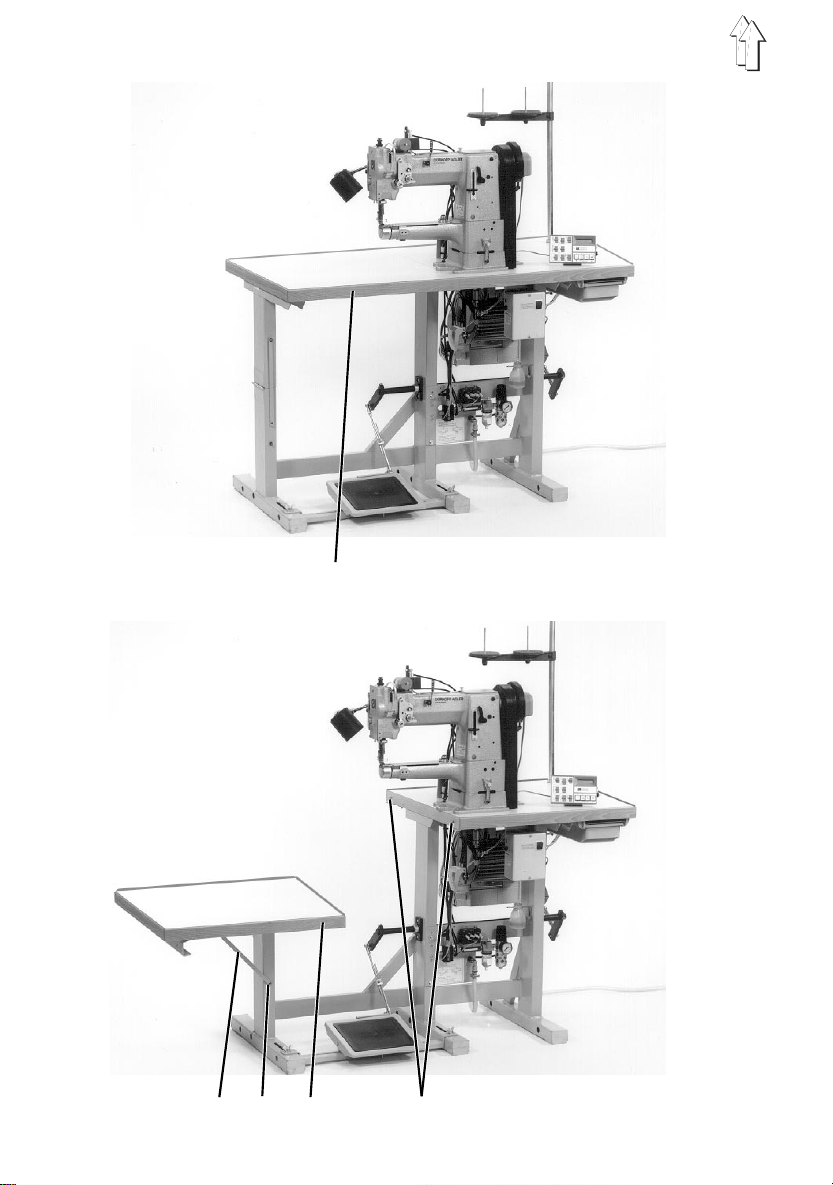
5.1 Folding down left-hand half of tab le plate (MG 56-2 f rame only)
When the special sewing machine is fitted with the
consists of two parts. The left-hand half 3 can be folded down to permit the
unobstructed manipulation o f large items ro und the free arm.
MG 56-2
frame the table plate
5
3
7
6
8
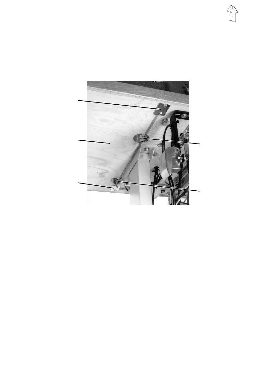
Folding down the left-hand half of the table plate
–
Turn fasteners 7 and 8 beneath the table plate anticlockwise to unlock the
left-hand half 3 of the table plate.
–
Fold the left- hand half 3 of the table plate down and to the l eft.
–
Hook shackle 1 onto the pin 2 of the left- hand frame upright.
Folding the left-hand half of the table plate back into place
–
Unhook shackle 1 from pin 2.
–
Lift the left-hand half 3 of the table plate, swivel it to the right and lower it onto
support plates 5 and 6.
The pins 4 in the right-hand half of the table plate must fi t i nto the holes i n the
left-hand half 3.
–
Turn fasteners 7 and 8 beneath the table plate clockwise to lock the left-hand
half 3 of the t able plate.
9
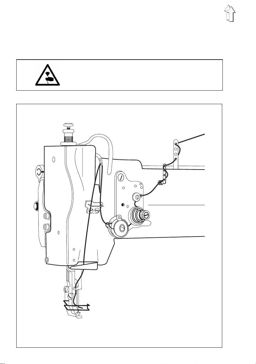
5.2 Threading the needle thread
5.2.1 Subclass 69-373
Caution: danger of injury
Turn off the main switch
The needle thread may only be threaded with the sewing
machine turned off.
10
5.2.2 Subclass 69-F A-373
Caution: danger of injury
Turn off the main switch
The needle thread may only b e t hreaded with the sewing
machine turn ed off.
11
1
2
3
12
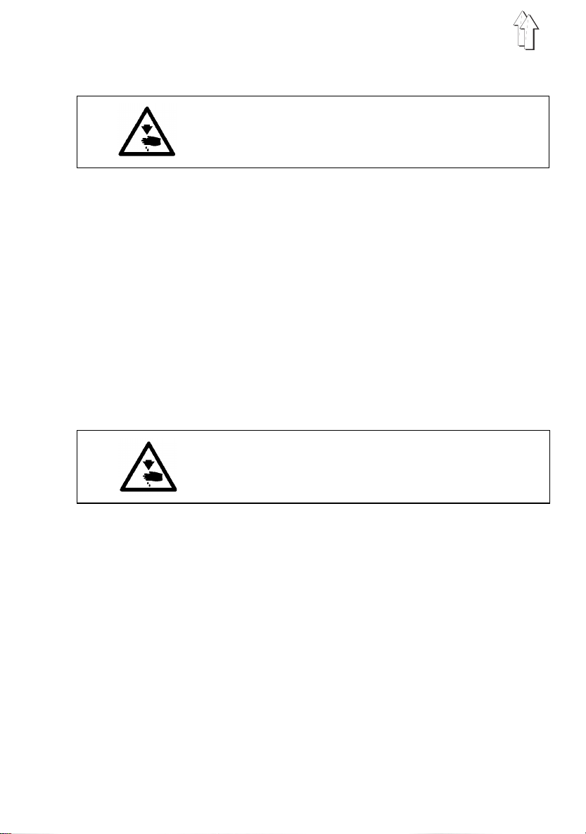
Fig. a: correct thread loop in the centre
Fig. b: needle-thread tension too weak or
Fig. c: needle-thread tension too strong
of the material
looper-thre ad tension too s t rong
looper-thread tension too weak
or

5.3 Adjusting the needle-thread tension
Pre-tensioning mechanism (subclass 69-FA-373)
On subclass
thread cutter to function reliably when the main tensioner 2 is open.
This residual tension is created by the pre-tensioning mechanism 1.
The pre-tensioning mechanism 1 also determines the length of the needle-thread end
after the thread has been clipped.
The pre-tension 1 should be set lower than the main tension 2.
–
Adjust pre-ten si oning mechani sm 1 by turning th e knurled nut.
–
After major changes to prel i minary tensi on 1 the main tension 2 should also be
adjusted accordingly.
Main tension
The main tension 2 should be set as low as possible.
The looping of the threads must be in the centre of the material (see fig. a).
With thin material excessive th read tension can cause unwanted gathering and thread
breakage.
–
Adjust the main tensioner 2 so that the stitches are uniform.
69-FA-373
the needle thread needs to be under residual tension for the
5.4 Opening the needle-thread tensioner
Automatic
The main tensioner 2 is opened automatically:
–
when the thread is severed (subclass
–
when the foo t is raised (pedal 1 position backwards)
69-FA-373
).
Manual
The main tensioner 2 is opened manually:
–
when the rele ase lever 3 is pr essed towards the arm.
The main tension er 2 remains open f or as long as pressur e is maintained on the
release lever 3.
–
when the sewing feet are raised mechanically with the knee lever (see chapter 5.9).
–
when the sewing feet are locked in the raised position (see chapter 5.10).
13

1
2 3
4
5
9
14
8 7 10 11
6 7 8
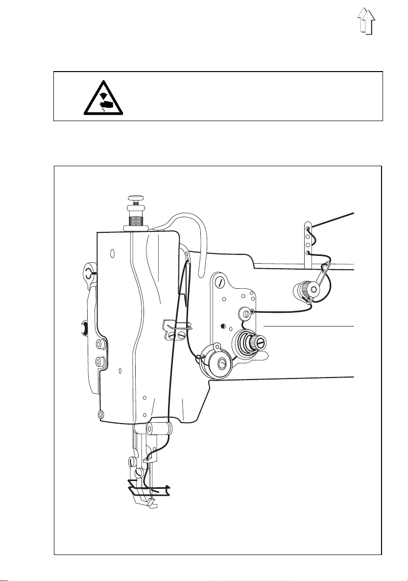
5.5 Winding on the looper t hread
Caution: danger of injury
Turn off the main switch.
The looper thread may be threaded for winding on only
when the sewing machine is switched off.
–
When winding on for sewing with no underlay material:
arrest the sewing feet in the up position (see chapter 5.10).
–
Thread looper thread as shown in the upper illustration.
–
Wind about 5 coi l s of looper thread clockwise onto the bobbi n core.
–
Place bobbin 3 on bobbin-winde r shaft 5.
–
Swivel bobbin-winder lever 4 against the bobbin.
The bobbin-wi nder wheel 2 is pr essed against t he V-belt.
–
Adjust tension 1.
The looper thr ead should be wo und on with mini m al t ension.
–
Sew.
The bobbin-wi nder lever 4 termi nates the process as soon as the bobbin is full.
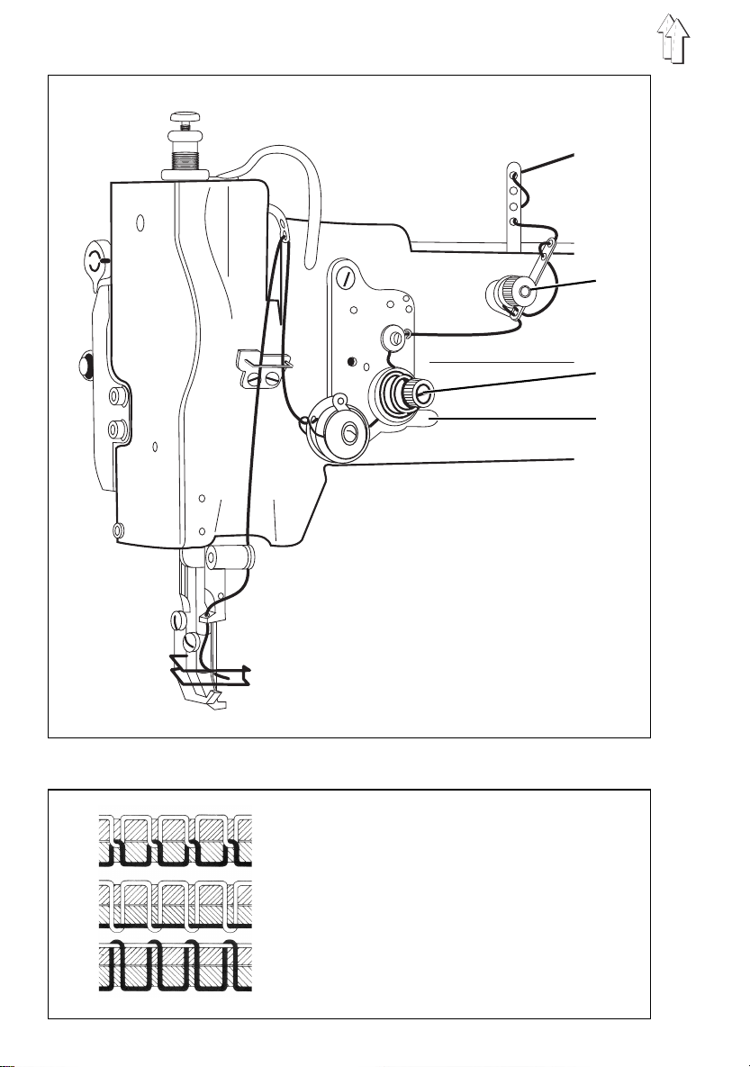
5.6 Fitting the looper-thread bob bin
Caution - danger of injury
Turn off the main switch.
The looper-thread bobbin may only be changed with the
sewing machine switched off.
Removing empty looper-thread bobbin
–
Turn handwheel until the needle bar reaches its highest position.
–
Pull off cap 6 in t he direction of t he arrow.
–
Raise bobbin-housing flap 8.
–
Remove top 7 of bobbin housing with bobbin.
–
Remove empty bobbin from top 7 of bobbin housing.
Threading looper thread
–
Place full bobbin 11 in top 7 of bobbin housing:
when the thread is wound off the bobbin 11 must rotate in the direction of the arrow.
–
Draw looper thread down through slit 10 under tensioning spring 9. Pull about 8
cm of looper thread out of the top 7 of the bobbin housing.
–
Replace top 7 of bobbin housing.
–
Close bobbin-housing flap 8.
15

1
3
2 4 5
16
6
7
8

5.7 Adjusting looper-thread tension
Caution: danger of injury
Turn off the main switch.
The looper-thread tension may only be adjusted with the
sewing machine switched off.
Adjusting brake spring 1 (class 69-FA-373)
On subclass
the machine halts or if the looper thread is wound off spasmodically.
–
Unscrew regulating screw 4 until no tension remains in tension spring 3.
–
Adjust brake spring 1 with regulating screw 5.
The braking force is correctly adjusted if brake spring 1 is about 1 mm above
surface 2.
Adjusting tension spring 3
–
Adjust tensio n spring 3 with regulating screw 4.
to increase looper-thread tension: turn screw clockwise
to reduce looper-threa d t ension: turn screw anticlo ckwise
For stitch for mation see sketc h a on page 12.
69-FA-373
the brake spring 1 prevents the bobbin from "running on" when
5.8 Fitting and changing the needle
Caution: danger of injury
Turn off the main switch.
The needle may o nl y be changed wi t h the sewing machi ne
switched off .
–
Turn the handwheel until the needle bar 6 reaches its highest position.
–
Undo screw 7.
–
Pull needle dow nwards out of needle bar 6.
–
Insert new needle
Caution:
When seen from the operati ng side of the m achine the f urrow 8 of the needle must
point to the rights(see sketch).
–
Tighten screw 7.
Failure to comply with this instruction can cause the following faults:
when fitting a thinner needle: faulty stitches, damage to thread
when fitting a thicker needle: damage to the shuttle tip and needle
as far as it will go
CAUTION:
When a thicker needle is fitted the distance from the
shuttle to the needle must bed corrected (see servicing
instructions).
into the hole in needle bar 6.
17

1
2 3
4
5
18
2
6

5.9 Lifting the sewing feet
The sewing feet are raised mechanically or electro-pneumatically, depending on which
mechanism is fitted to the machine.
Mechanical sewing-foot-raising mechanism
–
Operate knee lever 1.
The sewing feet remain raised as long as pressure is maintained on knee lever 1 [].
Electro-pneumatic sewing-foot-raising mechanism
(when FLP 14-2 or RAP 14-1 are fitted)
–
Push pedal half-way back.
The sewing fee t are raised with t he machine at a h al t .
–
Push pedal all the way back.
The thread clipper is activated and the sewi ng feet raised.
(with the machine at a halt)
5.10 Locking the sewing feet in the raised position
The mechanically or pneumatically raised sewing feet 3 are locked in the raised
position with lever 2 (e.g. for the looper thread to be wound on or the sewing foot
changed). Lever 2 is locat ed on the back of the machine arm.
–
With the mach i ne at a halt, swivel lever 2 up.
The sewing feet 3 are locked in the raised position.
–
Swivel lever 2 down.
The sewing feet are no longer locke d.
5.11 Adjusting the sewing-foot stroke
The height of the sewing-foot stroke is determined by the position of tension bar 6.
Caution: danger of injury
Turn off the main switch.
The sewing-foot stroke may only be adjusted with the
sewing machine switched off.
Adjusting the sewing-foot stroke
–
Undo nut 4 on the back of the machine arm.
–
Push tension bar 6 into rocker lever 5.
tension bar fully up: maximum sewing-foot stroke (4.5 mm)
tension bar fully down: minimum sewing-foot stroke (2.5 mm)
–
Tighten nut 4.
19

5.12 Adjusting the sewing-foot pressure
1
Sewing-foot pressure is adjusted with screw 1.
–
to increase sewing-foot pressure: turn screw 1 clockwise
–
to reduce sewing-foot pressure: t urn screw 1 ant i clockwise.
2
3
4
5.13 Adjusting the stitch length
Caution: danger of injury
Turn off the main switch.
The stitch length may only be adjusted with the sewing
machine switched off.
–
Turn wing-nut 2 anticlockwise as far as it will go.
–
Adjust the desired stitch length with screw 3.
To increase sti tch length: turn screw 3 anticlockwise.
To reduce stitch length: turn screw 3 clockwise.
–
Tighten wing-nut 2 clockwise.
To sew bar tacks manually (backwards sewing):
–
Swivel the stitch-length handle 4 up as far as it will go (to position "R").
The machine sews backwards as long as the stitch-length handle 4 is held up.
20
The stitch-length handle 4 moves down.
The stitch-length handle 4 moves up.

5.14 Welting
1
2
The rapid-adjustment welt-guide mechanism with three positions is used to sew welts
between two layers of material. It can be swivelled in or out at the beginni ng and end of
the seam.
Four welt guides 2 are available (sewing attachments E20 - E23) with welt grooves from
3 to 6 mm.
Caution: danger of injury
Turn off the main switch.
The welt may only be inserted with the sewing machine
switched off .
Inserting the welt
–
Undo screw 1.
–
Feed welt in through welt guide 2.
–
Adjust welt guide 2 to the width of the welt.
The welt must be guided at t he sides, but at the same ti me it must be easy to pull it
through the welt guide 2.
–
Tighten screw 1.
Sewing in the welt
–
Lay the welt between the two layers of material.
–
Pull out ball handle 4 and turn lever 3 as far as it will go to the left (position P).
–
Start sewing until the needle has reached approximately the middle of the welt.
–
To continue sewing in the welt pull out ball handle 4 and turn lever 3 to the centre
position (pos i tion S), where it engages.
–
At the end of t he seam pull out ball handle 4 and turn lev er 3 to its basi c position
(position 0).
3
4
21

5.15 Ribbon binder (class 69-373)
1
4 5 6
Two ribbon-binder sets are available for subclass
sewing attachment E4: for narrow bindings
sewing attachment E5: for broad bindings
Caution: danger of injury
Turn off the main switch.
The ribbon band may only be inserted with the sewing
machine switched off.
2
3
69-373
7
8
:
Inserting the ribbon band
–
Place the ribb on band on the lower pulley of the reel holder 3 .
–
Place upper pu l l ey and pressure spring 2 on reel holder 3.
–
Screw knurled nut 1 onto reel holder 3.
The ribbon band should be kept under slight pressure.
–
Slightly raise t he arm cover 6 and swivel it forwards (towards t he operating side).
–
Pass the ribbon band between the guide pins 5, through the ribbon guide 4, into
the ribbon binder 8 and under the sewing fee t.
–
Swivel the arm c over 6 back into p l ace.
Adjusting the distance of the seam from the ribbon edge
–
Undo screws 7.
–
Adjust the d i stance of the seam from the ribbon edge as required by mo vi ng the
ribbon binder 8.
–
Tighten screws 7.
22

6. Control unit and operating panel
CAUTION:
These operatin g i nstructions describe
the buttons and the change of parameters by the operator.
For a detailed description of the control unit please see the
current oper ating instruc tions of the m otor manufacturer
(supplied).
6.1 General
The control unit is program m ed and the seam functions set with the cont rol-unit buttons
or the operat i ng panel (for programming see motor manufacturer’s manual).
Depending on the seam requi red, sewing c an be executed manually or by
seam-progra mming (only wit h the operating panel).
Three different seam cycles can be programmed for various sewing requirements, in
which the various functions (starting bar tack, ending bar tack, stitch count, thread
cutting etc.) and parameter values (stitch rate, seam length, rpm etc.) are individually
assigned.
Entry is carried out in program m i ng mode.
The paramete rs and the values assigned are di splayed.
The seam progr a m s are not lost even when the sewing machin e i s switched off (battery
buffer).
In order to a void the inadvertent alteration of pre-set functio n s, operation is divided into
various levels (operator, technician).
The operator (seamstress) can program directl y.
Access to the technician lev e l i s contingent on the entry of a code numb er (EFKA) or on
switching on the main switch by simultaneously holding down two buttons (QUICK).
the functions of
only
RESET
If the control unit is hopelessly misadjusted, this function allows the technician to reset
all adjusted values to their default (ex-works) settings.
This function is described in the Servicing instructions.
23

6.2 Efka VD554KV/6F82AV sewing drive
6.2.1 Control-box buttons
In programming mode
button function
P
E
+
-
>>
24
programming m ode (start / end)
confirm parameter-val u e change
switch to ne xt paramete r
increase displayed parameter value
switch to ne xt paramete r
increase code no.
reduce displayed parameter value
switch to l ast parameter
reduce code no.
select next character in display

Button functions in sewing mode
button function after the thread has been clipped LED display
select programming mode
starting bar tack
- single *
- double *
- OFF
ending bar tack
- single *
- double *
- OFF
Automatic sewing-foot-raising mechanism
- when stopping in mid-seam
- at the end of the seam
- when stopping in mid-seam and at the end of
the seam
- OFF
Basic needle position
- up
- down
* Starting an d ending bar tacks cannot be sewn with this m a chine.
CAUTION:
The + and - butt ons increase or reduce the maximum rpm
before the thread is clipped
.
25

6.2.2 Altering parameter values
Parameter values are altered at operator level with the five buttons "P", "E", "+", "-" and
">>" on the sewing-drive control box.
The parameter list on the nex t page gives all parameters which c an be altered at
operator level.
1. Selecting programming mode
-
Press the "P" button.
The first parameter number (
2. Displaying the first operator-level parameter
-
Press the "E" button.
The appropriate parameter value (
3. Changing the displayed parameter value
-
Increase or reduce the pa rameter value with the "+" and "-" buttons.
If the "+" or "-" button is held down, th e parameter va lue continue s t o change unt i l
it is released.
4. Selecting the next parameter value
-
Press the "E" button.
The next operator-level parameter appears in the display.
-
Press the "E" button.
The appropria te parameter value appears i n the display.
Repeatedly pressing the "E" button successively calls up all operator-level parameters and parameter values.
When the param eter is displayed the + or - buttons can also be used to switch to
the next or previous parameter.
) appears in the display.
0 0 0
) appears in the display.
0. 0. 0.
5. Leaving programming mode
-
Press the "P" button.
The control unit leaves progra mming mode.
CAUTION:
The changed pa rameter values are not saved until a seam
is started by pressing the pedal down.
If the sewing machine is sw i tched off imme di ately after
programming without sewing, the changed parameter
values are
26
not
saved.

"Operator-level" parameter list:
Paramet er fun ction setti ng
max. min. ex wo rks
000 *
001 *
002 *
003 *
004 *
005
006
007
008
009
013
014
015
this parameter is vacant on this machine class
*
starting ba r-tack stitches forwards 254 0 2
starting ba r-tack stitches backwards 254 0 4
ending bar- tack stitches backwards 254 0 2
ending bar-tack stitches forwards 254 0 2
light-barr i er compensation stitches 254 0 7
* light-barrier filter stitch rate 254 0 0
for knitted yard goods
* number of light-b arrier seams 15 1 1
seam stitch rate with stitch count 254 0 20
assigning ato the "3" button 3 1 1
technician -l evel parameters
(only when operating the control unit
with a Variocontrol operating panel)
1 = softstart ON / OFF
2 = ornamental- st itch bar tack ON/OFF
3 = sewing-on with light barrier light
blocked ON / OFF
* light barrier ON / OFF OFF
* thread clipper ON / OFF ON
* thread retractor ON / OFF ON
stitch co unt OFF
27

6.3 Quick QD554/A51K01 sewing drive
6.3.1 Operating-panel buttons
button function in programming mode
28
select programming mode leave progra m m ing mode
(in conjunction with "-" button) (in conjunction with "-" button)
suppress starting / ending bar tack switch to n ext parameter
single depression:sew 1 stitch increase displayed value
held down: sew at n
change program reduce displayed value
(MANUALLY - SEAM-A - SEAM-B)
min
number

button function
ornamental bar tack
normal bar tack
starting double bar tack
starting single bar tack
starting ba r tack on
starting ba r tack off
sewing-foot position up before thread clipping
sewing-foot position down before thread clipping
ending bar tack double
ending bar tack single
ending bar tack on
ending bar tack off
smooth seam start
normal seam start
vacant
29

6.3.2 Altering parameter values
A operator level par am eter values a re changed wit h t he four program buttons ("G", "F",
"+", "-") on the right-hand side of the operating panel.
The parameter list on the nex t page gives all parameters which c an be altered at
operator level.
1. Selecting programming mode
-
Turn on the main switch.
"
MANUAL
-
Press and hold down the "G" button.
-
Press the "-" button.
"
- - - - - - >F
-
Release both buttons.
The control unit is in programming mode.
NB:
The sewing drive is inoperative in programming mode.
2. Selecting parameter number
-
Press the "G" button.
The button must be pressed r epeatedly until the group number (e.g. 6xx) appears.
-
Press the "F" button repeatedly until the required parameter number appears in
the display (e.g. "
If the "F" button is held down the parameter number continue s to change un t i l it is
released.
" appears in t h e display.
" appears in t h e display.
102*0002
").
3. Changing the displayed parameter value
-
Use the "+" and "-" buttons to increase or reduce the parameter value.
If the "+" or "-" button is held down the parameter number continues to change until it is released.
-
If you leave the parameter-number routine the last-displayed parameter value is
automatically saved.
4. Leaving programming mode
-
Simultaneously press the "G" and "-" buttons.
The control unit leaves progra mming mode.
The last-displayed parameter value is saved.
-
"
MANUAL
-
The control uni t i s r eady for use.
The new settin g s can be checked by executing a test seam.
" appears in the display.
-
30

"Operator-level" parameter list:
paramet er function setting
101
102
103
108
109
111*
201
301
302
303
505
506
507
508
521
this parameter is vacant on this machine class
*
switch betwee n seam programs MAB
(the "P" button executes the switch)
MAB: MANUAL - SEAM-A - SEAM-B
M+A: MANUAL - SEAM-A
M+B: MANUAL - SEAM-B
A+B: SEAM-A - SEAM-B
starting ba r tack - stitch rate forwards 0 255 2
starting ba r tack - stitch rate backwards 0 255 1
ending bar tack - stitch rate backwards 0 255 2
ending bar tack - stitch rate forwards 0 255 1
light-barrier compensation stitches 0 30 1
stitch rate of seam section A 0 255 20
stitch rate of seam section B1 0 255 10
stitch rate of seam section B2 0 255 10
number of seam sections B1 and B2 0 255 2
starting or namental bar tack - stitch 0 30 3
rate forwards
starting or namental bar tack - stitch 0 30 3
rate backwards
ending ornamental bar tack - stitch 0 30 3
rate backwards
ending ornamental bar tack - stitch 0 30 3
rate forwards
needle position before thread clipping III II
(I = up, II = dow n)
min . max. ex work s
31

7. Sewing
This description is based on th e following assu mptions:
–
the machine in question is a special sewing machine with thread clipper
(subclass
-
RAP 14-1
-
HP 11-1
–
The following f unctions are set at t he operating pan el :
starting bar tack: ON
ending bar tac k: ON
sewing-foot position bef ore and after clipping: DOWN
–
The main switch is on.
–
The last sewing operation was concluded with an ending bar t ac k and thread
clipping.
Operating and function sequence f or sewing:
sewing operation operation / explanation
69-FA-373
electro-pneumatic bar-t ack and sewing- foot-raising mechanism,
pedal-operated
pneumatic rapid stroke-adjustment mechanism, operated by a knee lever
) and the fol l owing optional extras:
Before starting sewing
starting po si tion
position material at start of
seam
At start of seam
sew starting bar tack and
continue sewing
sew only star t ing bar tack
do
sew starting bar tack
not
- pedal i n neutral position
the machine is at a standstill
needle up - sewing feet down
- move pedal back and hold it there
the sewing feet rise
- place material under the needle
- release the pedal
the sewing feet lower onto the material
- move pedal forward and hold it there
starting ba r tack is sewn
the machine then continues sewing at the
motor speed set by the pedal
- move pedal briefly forwards
the machine stops after sewing the
starting ba r tack in the needle-down position
-press "F" button (suppress starting bar tack)
- move pedal forward and hold it there
the machine then sews at the
motor speed set by the pedal
- the next seam is begun with a starting bar tack
32

sewing operation operation / explanation
In mid-seam
interrupt sewing operation
resume sewing operation
sew transverse seam
(with rapid stroke-adjustment
mechanism)
At the end of the seam
remove material
do not raise sewing feet
do not sew ending bar tack
- release pedal (neu tral position )
the machine s t ops in the needle-down position
the sewing feet are lowered
-press the "F" button (ending bar-tack
suppression)
- move pedal briefly backwards
the machine assumes the needle-up position
- move pedal forwards
the machine sews at the motor speed
set by the pedal
starting bar tack is sewn
no
- operate knee switch
the maximum sewing-foot stroke is activated
the operatin g t i m e depends on what mode the
rapid stroke-adjustment mechanism is set to:
a) switch mode:
- activated until knee switch is operated again
b) key mode:
- activated for as long as knee switch is
operated
- move pedal back and hold it there
the ending bar tack is sewn
the thread is severed
the machine assumes the needle-up position
the sewing feet rise
- move pedal briefly backwards
the ending bar tack is sewn
the thread is severed
the machine assumes the needle-up position
the sewing feet remain lowered
-press the "F" button (ending bar-tack
suppression)
- move pedal back
the ending bar tack is not sewn
the thread is severed
the machine assumes the needle-up position
the position of the sewing feet depends on the
position of the pedal:
a) pedal pressed backwards and held:
- sewing feet raised
b) pedal released (i n neutral position):
- sewing feet lowered.
33

8. Maintenance
Caution: danger of injury
Turn off the main switch!
Maintenanc e work may only be carried out on the sewing
machine when it is switched off.
Maintenance work must be carried out no less frequently than at the intervals given in
the tables ( see "operating hours" column).
Maintenanc e i ntervals may need to be shorter when processing heavy -shedding
materials.
8.1 Cleaning and testing
A clean sewing machine i s a trouble-free sewing ma chine.
6
4
8
2
10
1
34
2
3

maintenance work explanation operating
to be carried out hours
Upper part of machine
- Remove lint, pi eces of
thread and other debris.
Sewing drive
- Check the co ndition and
tension
of the V-belt.
Compressed-air
maintenance
unit (optional extra)
- Check the water level in
the pressure regulator.
Places in specia l need of cleanin g:
- area under the needle plate
- feeder
- area around the shuttle
- bobbin housing
- needle-thread tensioner
- thread clipper (class 69-FA-373)
It must be p ossible to depress the V-belt
by about 10 mm by pressing on it with a
finger at its mid-point.
The water leve l must not reach
the filter insert 2.
- After screwing in the drain plug 3 blast
the water out of the water separator
under pressure.
8
160
40
- Clean the filter insert.
NB:
The water separator 2 is fitted with a
semi-automatic condensation drain.
Condensation is automatically drained
when the pressure falls below a pre-set
level.
Dirt and condensation ar e separated by
filter insert 1.
- Disconnect the machine from the
compressed-air supply.
- Screw in drain pl ug 3.
There must be no pressure in the
machine’s pneumatic system.
- Unscrew water separator 2.
- Unscrew filter i n sert 1
Wash the filter shell and insert
with cleaning fluid (
and blast clean.
- Re-assemble and connect the
maintenance unit.
not
solvent)
500
35

1 2 3 4 5 6 7 8
9 10 11
36

8.2 Lubrication
Caution: danger of injury
Oil can cause skin eruptions.
Avoid protracted contact wit h the skin.
In the event o f contact, thor oughly wash the a ffected area.
CAUTION:
The handling an d disposal of mi neral oils is subject to legal
regulation.
Deliver used oil to an authorised collection point.
Protect your environment.
Take care not to spill oil.
To lubricate the special sewing machine use only
ESSO SP-NK 1 0
or an equivalent oil of the fo l l owing specifica t i on:
–
viscosity at 40° C : 10 mm2/s
–
flashpoint: 150 °C
lubricating oil
ESSO SP-NK 1 0
following part numbers:
2-litre container: 9047 000013
5-litre container: 9047 000014
maintenance work explanation operating
to be carried out hours
oil lubrication points 1 to 17
is available from
DÜRKOPP AD LER AG
- Remove the top.
- Oil all the lubrication points shown
in the illustration with a few drops
of oil.
NB:
Subclass
lubrication point 8.
69-FA-373
retail outlets under the
has no
12 13 14 15 16 17
40
37

9. Optional extras
9.1 HP 1 1-1 pneu matic rapid st roke adjuster
The HP 11-1 pneumatic rapid stroke adjuster is only available for special sewing
machines with the
This optional extra allows a larger sewing-foot stroke to be set in mid-seam
(e.g. for t h i cker pieces of m aterial or to oversew transv erse seams).
Quick QD554/A51K01
sewing drive.
1
–
Operate knee switch 1.
This activates the maximum sewing-foot stroke, which has two operating modes.
Operating modes
The rapid stro ke-adjustment m echanism can be used in either
The desired operating mode is determined by the setting of parameter number
technician l evel - see servic i n g instructio ns or motor manufacturer’s manual (supplied).
mode operation / explanation
switch mode activated until the knee switch is operated again
401 = I - Operat e knee swit ch.
The maximu m sewing-foot stroke is activated.
- Operate knee switch again.
The seam is continued with the set sewing-foot stroke.
touch mode activated until the knee swit ch i s released
401 = II - Oper ate knee switch and hold it i n place.
The maximu m sewing-foot stroke is activated.
- Release knee switch.
The seam is continued with the set sewing-foot stroke.
switch
or
touch mode
401
at
38
.
 Loading...