


Contents Page:
Home
Part 2: Installation Instructions Cl. 506
1. Scope of Delivery
2. Installation of the Unit
2.1 Transport . . . . . . . . . . . . . . . . . . . . . . . . . . . . . . . . . . . . . . . . . . . . . . . . 3
2.2 Setting the Work Height . . . . . . . . . . . . . . . . . . . . . . . . . . . . . . . . . . . . . . . . 3
2.3 Attaching the Yarn Stand . . . . . . . . . . . . . . . . . . . . . . . . . . . . . . . . . . . . . . . 4
2.4 Checking the V-belt Tension . . . . . . . . . . . . . . . . . . . . . . . . . . . . . . . . . . . . . 4
3. Electrical Connection
3.1 Connecting the Microcontrol Control Unit . . . . . . . . . . . . . . . . . . . . . . . . . . . . . . 5
3.2 Checking the Nominal Voltage . . . . . . . . . . . . . . . . . . . . . . . . . . . . . . . . . . . . 6
3.3 Setting the Motor Protection Switch . . . . . . . . . . . . . . . . . . . . . . . . . . . . . . . . . 6
3.4 Checking the Direction of Rotation of the Motor . . . . . . . . . . . . . . . . . . . . . . . . . . 7
3.5 Checking the Positioning . . . . . . . . . . . . . . . . . . . . . . . . . . . . . . . . . . . . . . . 8
4. Pneumatic Connection
. . . . . . . . . . . . . . . . . . . . . . . . . . . . . . . . . . . . . . . . . . . 3
. . . . . . . . . . . . . . . . . . . . . . . . . . . . . . . . . . . . . . . . 3
. . . . . . . . . . . . . . . . . . . . . . . . . . . . . . . . . . . . . . . . 5
. . . . . . . . . . . . . . . . . . . . . . . . . . . . . . . . . . . . . . . . 9
1. Scope of Delivery
2. Installation of the Unit
–
Frame with se win g d r i ve a nd ta bl e 1100 x 736 mm
–
Sewing machine with integrated bobbin winder
–
Microcont rol c o nt r ol u ni t
–
Compressed air maintenance unit
–
Ya rn sta nd
–
Foot switches
–
Sewing light
–
Tools and small parts in the accessories pack
ATTENTION !
The unit may only be set up by trained personnel.
Before installing the unit it is essential that all transport fastenings be
removed!
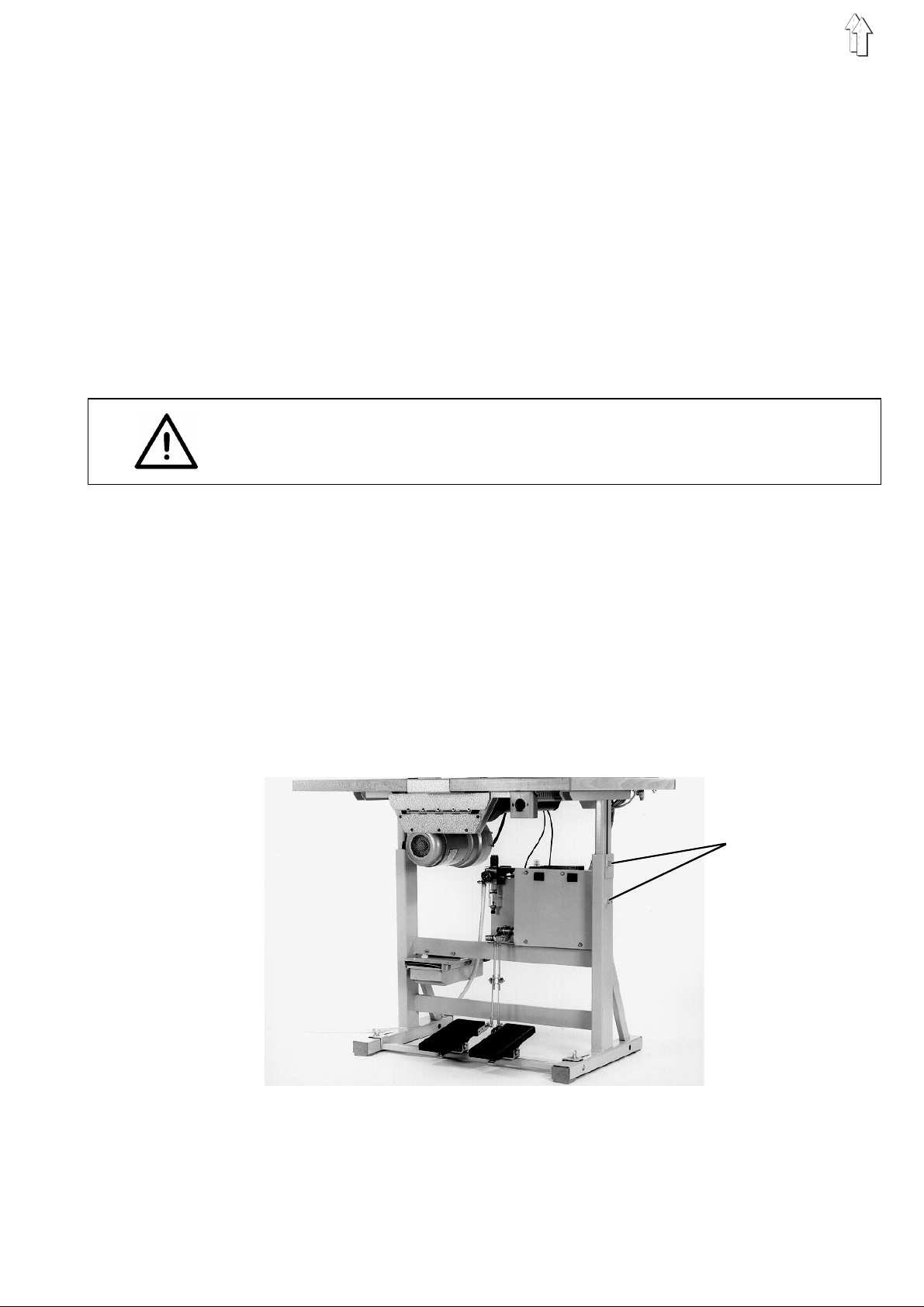
2.1 Transport
2.2 Setting the Work Height
For in-house transport lift the unit and transport on a suitable wagon
(e.g. lift truck).
The work height can be set between 76 cm and 106 cm (measured to
the upper edge of the table).
The unit is set at a work height of 82 at the factory.
1
–
Loosen the locking screws 1 on both sides of the frame.
–
Set the base plate horizontally at the desired work height.
In order to avoid a tilt pull out or push in the base plate uniformly
on both sides .
–
Tighten the locking screws 1.
3
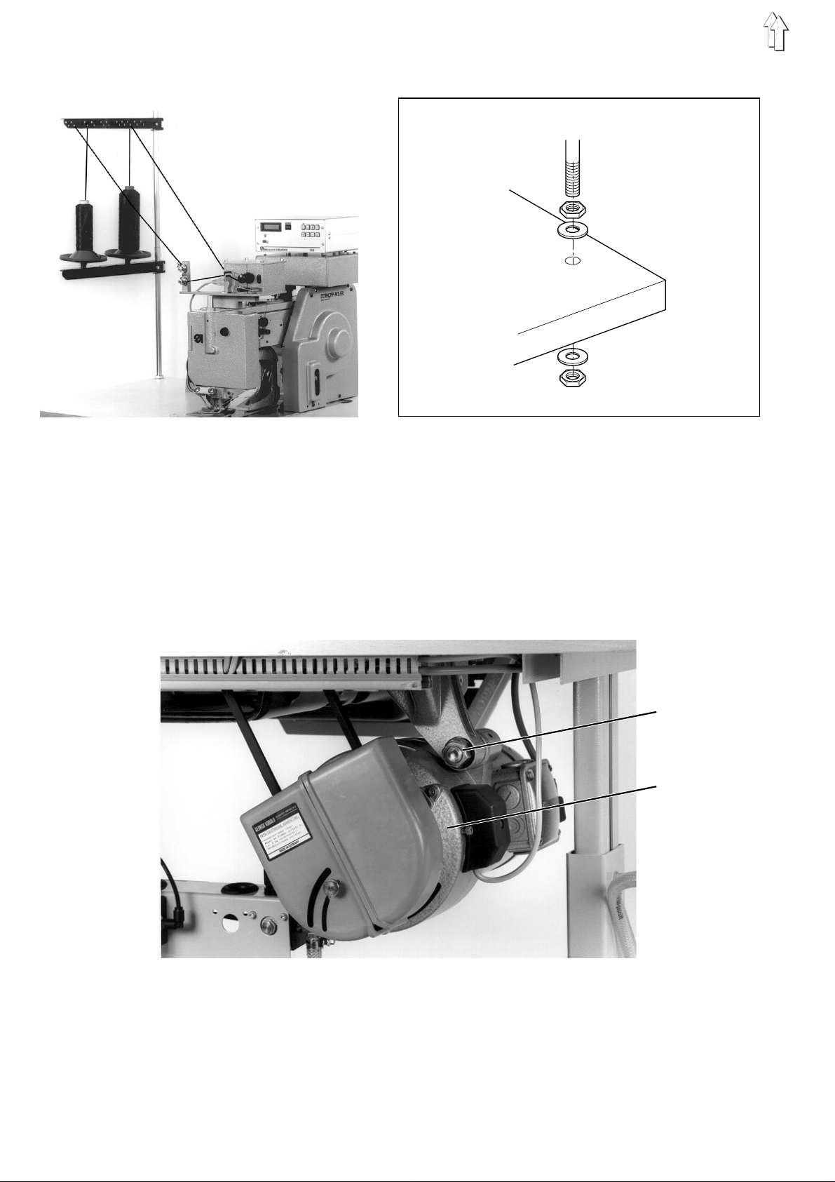
2.3 Attaching the Ya rn Stand
–
Insert the ya rn s t an d i n to the appropriate h ol e i n t he table and
attach with the nuts and washers.
2.4 Checking the V -belt Tension
After transport the V-belt tension set at the factory is to be checked.
The notched V-belt must be under sufficient tension for the unit to run
softly into th e e nd po s iti o n.
Tension the V-belt so that it can be pushed in at the center approx.
10 mm by finger p r ess u r e.
1
2
Correcting the V-belt tension:
–
Loosen nut 1.
–
Swing the s ew i ng dri v e 2 u nt i l th e d es i re d V-belt t en si on i s
achieved.
–
Tighten nut 1.
4

3. Electrical Connection
ATTENTION !
All work on the electrical components of the s ewing unit may b e
carried out only by electr ic i an s or a ppropriately t rai n ed personnel.
The mains plug must be pulled.
3.1 Connecting the Microcontrol Control Unit
The Microcontrol control unit is equipped with the catch plate 1 for
quick attachment and removal.
1
–
Place the Microcontrol control unit on the catch plate 1 and push
back until it catches.
–
Make the cable connections.
Attention !
Insert the pl ug s c are fu l l y into the back of th e c o nt r ol u nit.
In as far as these are present, match the designations on the
cables and the unit back.
Also observ e t he di ffer e nt ou tf i tting of the plug s wi t h c o nt ac t pi n s
or contact sockets, as well as their number and arrangement.
–
Tighten the screws on the plugs.
5

3.2 Checking the Nominal Voltage
The nominal voltage listed on the rating plate of the sewing drive and
the mains vol t ag e m us t ag r ee !
For conversi on to a different mains v ol t ag e t he appropriate vol t ag e k i t
must be mounted.
The voltage kit consists of:
V-belt pulley, V-belt, protection switch insert
Nominal voltage: Order no.:
3 ~ 380 - 415 V + N, 50 Hz 9880 506001
3 ~ 220 - 240 V, 50 Hz 9880 506002
3 ~ 220 - 240 V, 60 Hz 9880 506003
Delta"
"
When converting to a different mains voltage the wiring must be
changed. The wiring is shown in the components connection schematic.
The bridges i n t he motor terminal b ox a re to be switched i n "
Delta
"
" according to the mains voltage .
3.3 Setting the Motor Protection Switch
The motor prot e cti o n s w i tc h 1 m us t be s et ac c o rdi n g t o t he mains
voltage.
220 - 240 V: 2.5 - 4 A
380 - 415 V: 4 - 6.3 A
"Star"
Star
" or
1
6

3.4 Checking the Direction of Rotation of the Motor
ATTENTION !
Before commisssioning of the unit it is essential that the direction of
rotation of the motor be check e d.
Turning the unit on with an incorrect direction of rotation can cause
damage to the u ni t .
The direction of rotation of the ventilator fan on the sewing drive must
agree with the dir e cti o n o f r o ta tio n s h ow n i n th e p i ctu r e (c lo c k wi se ) .
–
Insert the mains plug.
–
By turning on the main switch for a brief period check the direction
of rotation of the ventilat or f an .
–
With an incorrect direction of rotation check if the current supply
creates a rig ht - ha nd r ot ary f i el d .
In this case 2 p ha s es o n the mains plug mu s t b e i n te rc ha ng ed .
7

3.5 Checking the Positioning
1
Before commissioning check the positioning set at the factory.
2
After being t ur n ed on th e u ni t mu s t p os i t i on i n t he 2n d n ee dl e po s i ti o n
(thread lever h i gh po s i tion).
Checking the positioning
–
Turn the main switch off.
–
By turning the ha nd wh ee l bri n g t he th rea d l e v er i n to a m idd l e
position.
–
Turn the main switch on.
The unit pos i ti o ns i n th e 2nd needle posi t i on
(thread lever high position).
–
Check the position of the thread lever.
Correct the positioning if necessary.
Correcting the positioning
–
Loosen the cl am pi n g s c re w s 2 on the synchronizer ring 1.
–
Hold the synchronizer ring 1 tight.
–
By turning the handwheel bring the thread lever into its upper dead
center.
–
Tighten the clampin g s c rews 2.
–
Check the positioning again.
For setting the 1st and 3rd needle positions see the Service
Instructions.
8

4. Pneumatic Connection
1
2
3
For the operation of the clamp lifting, thread tension opening, needle
cooling, etc. the unit must be supplied with water-free, lightly oiled
compressed air.
ATTENTION !
For a flawless functioning of the pneumatic control processes the
compressed air supply must be laid out as follows:
Even at the in s ta nt of greatest air c o ns u mp ti o n t he mi n i mu m o pe r at i ng
pressure may no t f al l b elo w
5 bar
.
4
Connecting the compressed air maintenance unit
–
Connect the connection hose 3 for the maintenance unit to the
compressed air supply with the enclosed coupling.
Filling the oil reservoir of the oil mister
For filling the oil reservoir use only
SP-NK 10 can be obtained from
–
Shut the co mp res s e d a i r off c om pl e te l y by turning the kn ob 1
counterclockwise.
–
Screw out the oil filler screw 4.
–
Fill the oil reservoir 5 up to the groove marking with
ESSO SP-NK 10
–
After filling the oil release the compressed air again by pulling up
on and turning th e k n ob 1 c l o c kw i se .
Setting the operating pressure
–
The operating pressure is
It can be seen on the pressure gauge 2.
–
For setting the operating pressure pull knob 1 up and turn.
Turning clockwise = Increase pressure
Turning counterclockwise = Decrease pressure
lubricating oil.
ESSO SP-NK 10
DÜRKOPP ADL ER AG
6 bar
.
lubricating oil.
sales offices.
5
9
 Loading...