


Contents Page:
Home
Part 4: Instructions for programming DA-Microcontrol Cl. 506
Program v ersion: 50 6 B03
1. General
2. Description of the Controls
2.1 Keys on the Front Panel . . . . . . . . . . . . . . . . . . . . . . . . . . . . . . . . . . . . . . . . 4
2.2 Internal Switches . . . . . . . . . . . . . . . . . . . . . . . . . . . . . . . . . . . . . . . . . . . . 5
2.3 Display . . . . . . . . . . . . . . . . . . . . . . . . . . . . . . . . . . . . . . . . . . . . . . . . . 6
3. Description of the Function Keys
3.1 Softstart . . . . . . . . . . . . . . . . . . . . . . . . . . . . . . . . . . . . . . . . . . . . . . . . . 7
3.2 Foot Switch Mode . . . . . . . . . . . . . . . . . . . . . . . . . . . . . . . . . . . . . . . . . . . 7
3.3 Burner Settings . . . . . . . . . . . . . . . . . . . . . . . . . . . . . . . . . . . . . . . . . . . . . 8
3.4 Machine Head Rpm . . . . . . . . . . . . . . . . . . . . . . . . . . . . . . . . . . . . . . . . . . 8
3.5 Bobbin Change . . . . . . . . . . . . . . . . . . . . . . . . . . . . . . . . . . . . . . . . . . . . . 9
3.6 Resetting the Counter for the Bobbin Winder . . . . . . . . . . . . . . . . . . . . . . . . . . . . 9
3.7 Resetting the Piece Counter . . . . . . . . . . . . . . . . . . . . . . . . . . . . . . . . . . . . . 9
4. Calling up the Sewing, Service and Testing Programs
5. Base Position a n d O per ati o nal Re ad i nes s
. . . . . . . . . . . . . . . . . . . . . . . . . . . . . . . . . . . . . . . . . . . . . . . . . 3
. . . . . . . . . . . . . . . . . . . . . 10
. . . . . . . . . . . . . . . . . . . . . . . . . . . . 11
6. Sewing Programs
6.1 Sewing Program P01 . . . . . . . . . . . . . . . . . . . . . . . . . . . . . . . . . . . . . . . . . 12
6.2 Sewing Program P02 . . . . . . . . . . . . . . . . . . . . . . . . . . . . . . . . . . . . . . . . . 12
6.3 Sewing Program P03 . . . . . . . . . . . . . . . . . . . . . . . . . . . . . . . . . . . . . . . . . 12
6.4 Sewing Program P11 . . . . . . . . . . . . . . . . . . . . . . . . . . . . . . . . . . . . . . . . . 13
7. Service Programs
7.1 Setting the Underthread Counter . . . . . . . . . . . . . . . . . . . . . . . . . . . . . . . . . . . 14
7.2 Programming Variable rpm Ranges . . . . . . . . . . . . . . . . . . . . . . . . . . . . . . . . . 14
7.3 Burner T est: Glowing . . . . . . . . . . . . . . . . . . . . . . . . . . . . . . . . . . . . . . . . . 16
7.4 Burner T est: Lowering and Glowing . . . . . . . . . . . . . . . . . . . . . . . . . . . . . . . . . 16
7.5 Burner T est: Lowering in Stages . . . . . . . . . . . . . . . . . . . . . . . . . . . . . . . . . . . 16
7.6 Burner T est: Slow Sewing, Lowering in Stages . . . . . . . . . . . . . . . . . . . . . . . . . . . 17
8. Testing Programs
8.1 Displaying the Program Version and Check Sum . . . . . . . . . . . . . . . . . . . . . . . . . . 18
8.2 Checking the Serial Interface . . . . . . . . . . . . . . . . . . . . . . . . . . . . . . . . . . . . . 18
8.3 Memory Test and Timer Test . . . . . . . . . . . . . . . . . . . . . . . . . . . . . . . . . . . . . 19
8.4 Continuity Test . . . . . . . . . . . . . . . . . . . . . . . . . . . . . . . . . . . . . . . . . . . . . 20
8.5 Checking the Front Panel Elements . . . . . . . . . . . . . . . . . . . . . . . . . . . . . . . . . 20
8.6 Checking the Input Elements . . . . . . . . . . . . . . . . . . . . . . . . . . . . . . . . . . . . . 20
8.7 Calling Up Input Elements . . . . . . . . . . . . . . . . . . . . . . . . . . . . . . . . . . . . . . . 21

Contents Page:
8.8 Calling Up Output Eleme nts . . . . . . . . . . . . . . . . . . . . . . . . . . . . . . . . . . . . . 22
8.9 Sewing Drive: Rpm Test, Position 2 . . . . . . . . . . . . . . . . . . . . . . . . . . . . . . . . . 23
8.10 Sewing Drive: Rpm Test, Position 1 . . . . . . . . . . . . . . . . . . . . . . . . . . . . . . . . . 23
8.11 Sewing Drive: Rpm Test, Position 1, Position 2 . . . . . . . . . . . . . . . . . . . . . . . . . . 23
9. Function Displays and Error Messages
9.1 Displays of Operating Aids . . . . . . . . . . . . . . . . . . . . . . . . . . . . . . . . . . . . . . 24
9.2 Displays of Malfunctions . . . . . . . . . . . . . . . . . . . . . . . . . . . . . . . . . . . . . . . 24
9.3 Error Messages . . . . . . . . . . . . . . . . . . . . . . . . . . . . . . . . . . . . . . . . . . . . 25

1. General
MICROCONTROL controls
The
as an integra l pa rt the comprehensi v e
monitoring system.
A microcomputer assumes the control tasks, monitors the sewing
process and displays operator errors and malfunctions.
Special programs simplif y m ec h an i c al se ttings and make po ss i bl e th e
quick inspec t i on of i np ut and output elem en ts without additi o na l
measuring de v ic es .
Errors and test results are shown in a 2 x 16 digit display.
During fault- fre e f un c ti o nin g t he di s p lay s h ow s i nf or m at ion to th e
operation and the sewing process.
With an opera to r err o r or a ma l fu nc t i on th e f un c ti o n s e qu en c e i s
interrupted . The cause is sho wn i n t he di s p l ay by the appropriat e er ro r
symbol.
In most cases the error symbol disappears after the cause of the error
has been remed i ed .
In some cases the main switch must be turned off for safety reasons
while the error is being corrected.
A part of the error messa ge s i s me an t o nl y f or t he maintenance s t aff.
All functions can be called up and changed by pressing the
appropriate key. For this the unit must be in the base position.
When the uni t i s t ur n ed on th e c o nt r ol s c o nd uc t a n um ber of
comprehensive self-tests. Thereby the program and data memories
and the displ ay, among other t hi n gs, are checked as t o f l aw l es s
functioning .
After the ma chi n e i s t urned off the set val ue s of the individua l
functions ar e st o red i n t he pr o gr a m a nd da ta me mo r i es ( b at te r y
buffered) and automatically activated when next turned on.
of the
DÜRKOPP ADL ER 50 6
MULTITEST
testing and
have
3
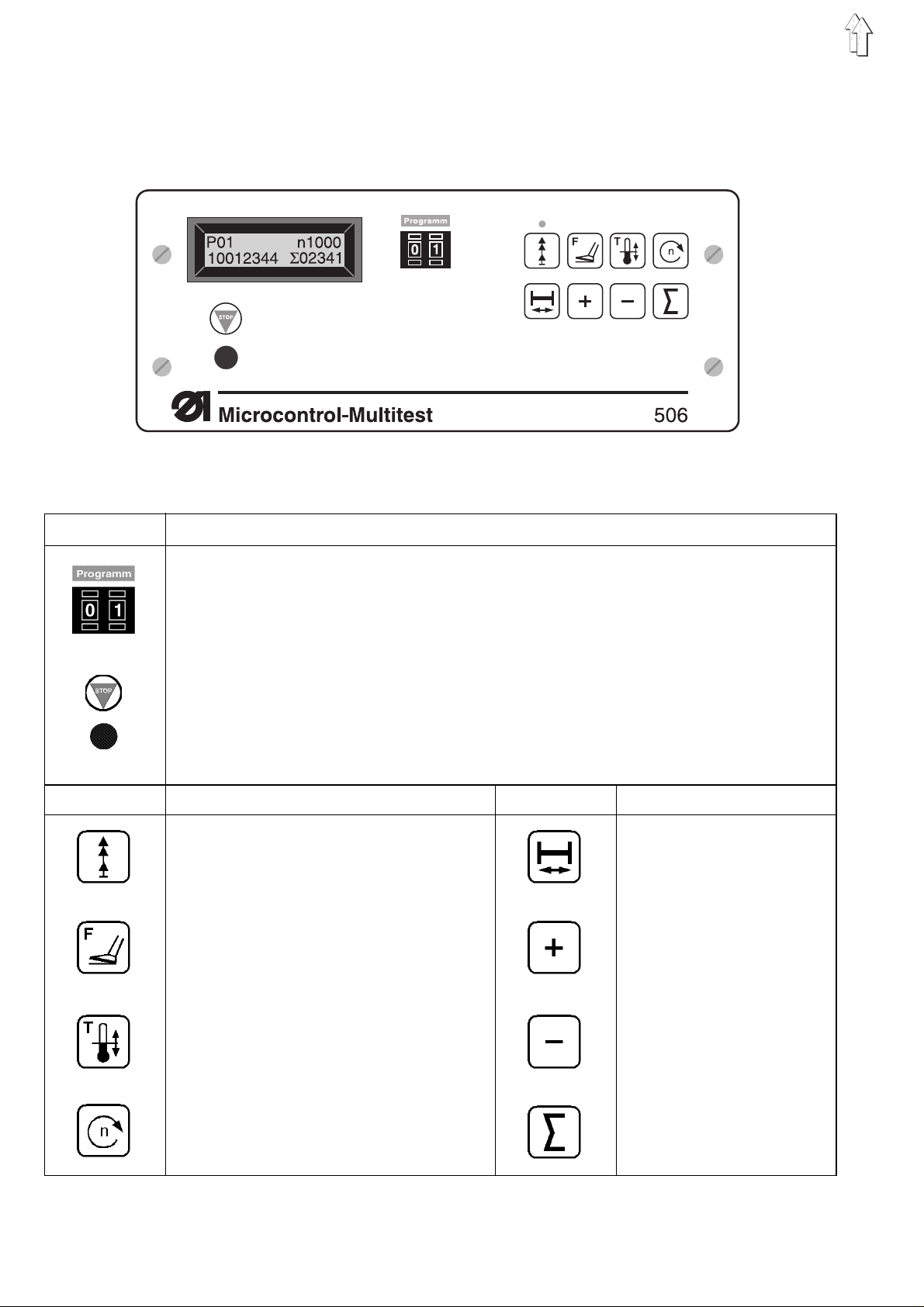
2. Description of the Controls
2.1 Keys on the Front Panel
Key Function
Calling up sewing and testing programs
Stopping the current program
Activating the selected program
Key Function Key Function
Switching t he softstart on / o ff Bobbin chang e
Setting the fo ot s wi t c h m od e Increasing th e p ara me ter
value
Setting the bu rne r Decreasing th e p ara me te r
value
Setting the rpm Setting the counter
4
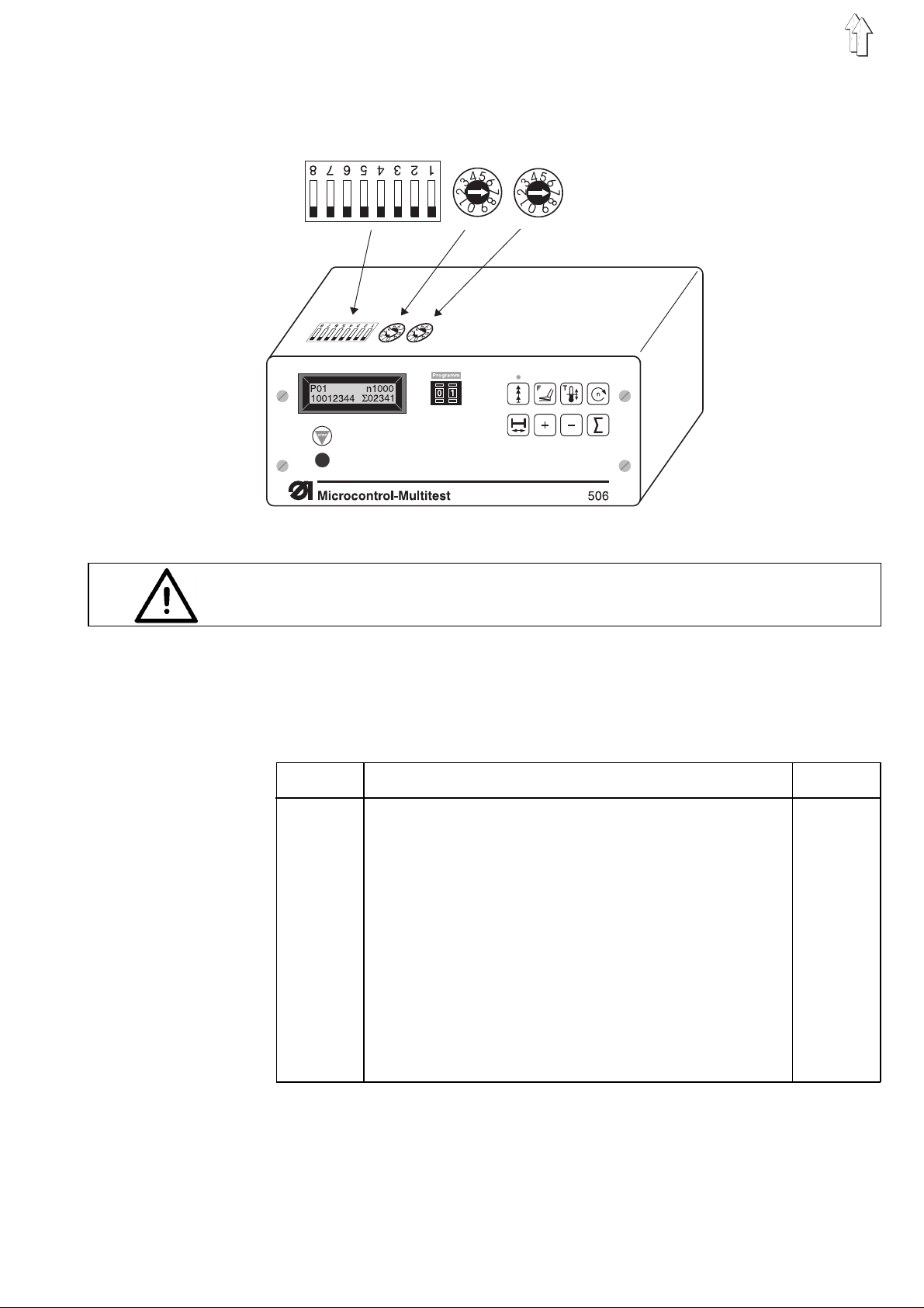
2.2 Internal Switches
on
off
DIP switch b500
Caution Electrical Current !
Set the switch only with the main switch turned off.
DIP switch b500:
With the aid of the internal DIP switch b500 the number of stitches per
curve disk revolution is set.
The allowable settings are to be found in the following table.
Switch12345678No. of Stit.
off off off off off X Y Z 42
on off off off off X Y Z 58
off on off off off X Y Z 72
on on off off off X Y Z 84
off off on off off X Y Z 116
on off on off off X Y Z 144
off on on off off X Y Z 21
on on on off off X Y Z 29
off off off on off X Y Z 36
on off off on off X Y Z 14
off on off on off X Y Z 24
off on off on off X Y Z 168
6: X = on: needle cool i ng no r ma l
6: X = off: needle cooling continuous operation
7: Y = on: without burner
7: Y = off: with burner
8: Z = on: w i th transport lever
8: Z = off: withou t t r an spo r t l e v er
5
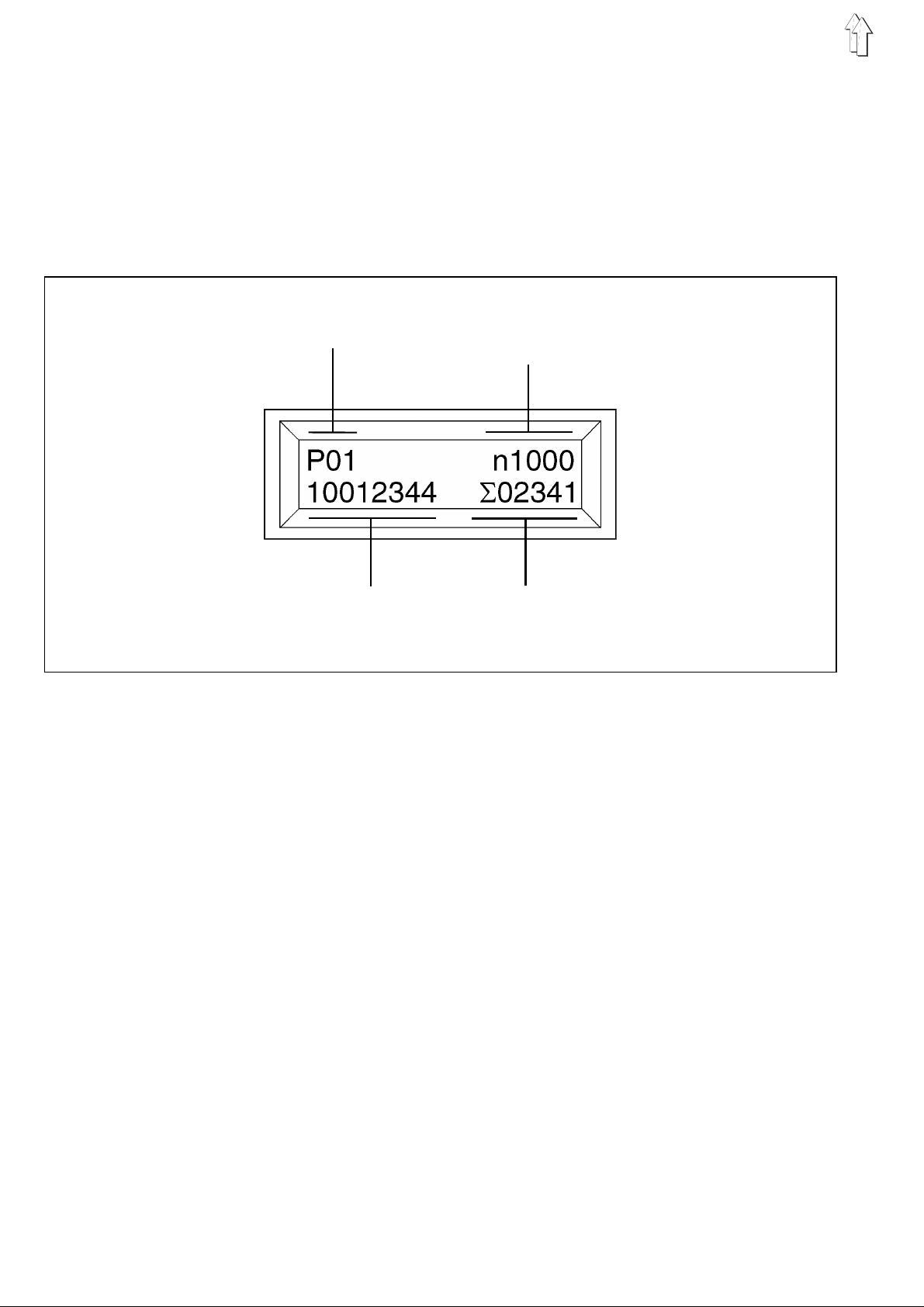
2.3 Display
The Microcontrol controls are equipped with a 2 x 16 digit display.
It shows the program number, machine head rpm and piece count.
With operato r err o rs or m al f un c ti o ns the function s eq ue nce is
interrupted an d t he c au s e s h ow n b y th e a pp r op ri at e e r ror s ymbol.
The display o f the piece coun t in the right half o f t he s eco nd half of the
display signals the operational readiness of the unit.
Program Numb er Machine Head Rp m ,
Error Messages
Production Counter Piece Counter
Program number
The left half of the first line o f t he di s p l ay s h ows the number of th e j u st
selected program.
Machine head rp m / er ror me ss ag e s
The right half of the first li n e o f the display sh ow s th e c u rr en tl y set rpm
of the machine head.
By the occura nc e of an operator error or malfunctions the appropriate
error symbol is shown.
Production counter
The production counter shows the sum of the pieces sewn up to that
moment. It ca nn ot be r es e t.
Piece counter
The piece counter shows the number of pieces sewn since the last
resetting of th e c o un te r. It can be res e t t o z e ro by pressing th e "Σ" key.
When the main switch is tu rned off the current count of the piece
counter is stored.
If the display remains blank after the main switch is turned on
then the 1.6 A fuse (on the underside of the mains unit) is to be
replaced.
6
3. Description of the Function Keys
The values for the various functions can be set as follows:
–
Call up the desired function by pressing the appropriate function
key.
The selected function is shown in the display with a blinking cursor.
–
Change the set value with the "
–
Press the sa me function key aga i n.
The change is completed.
The unit is re ad y fo r op era t io n again.
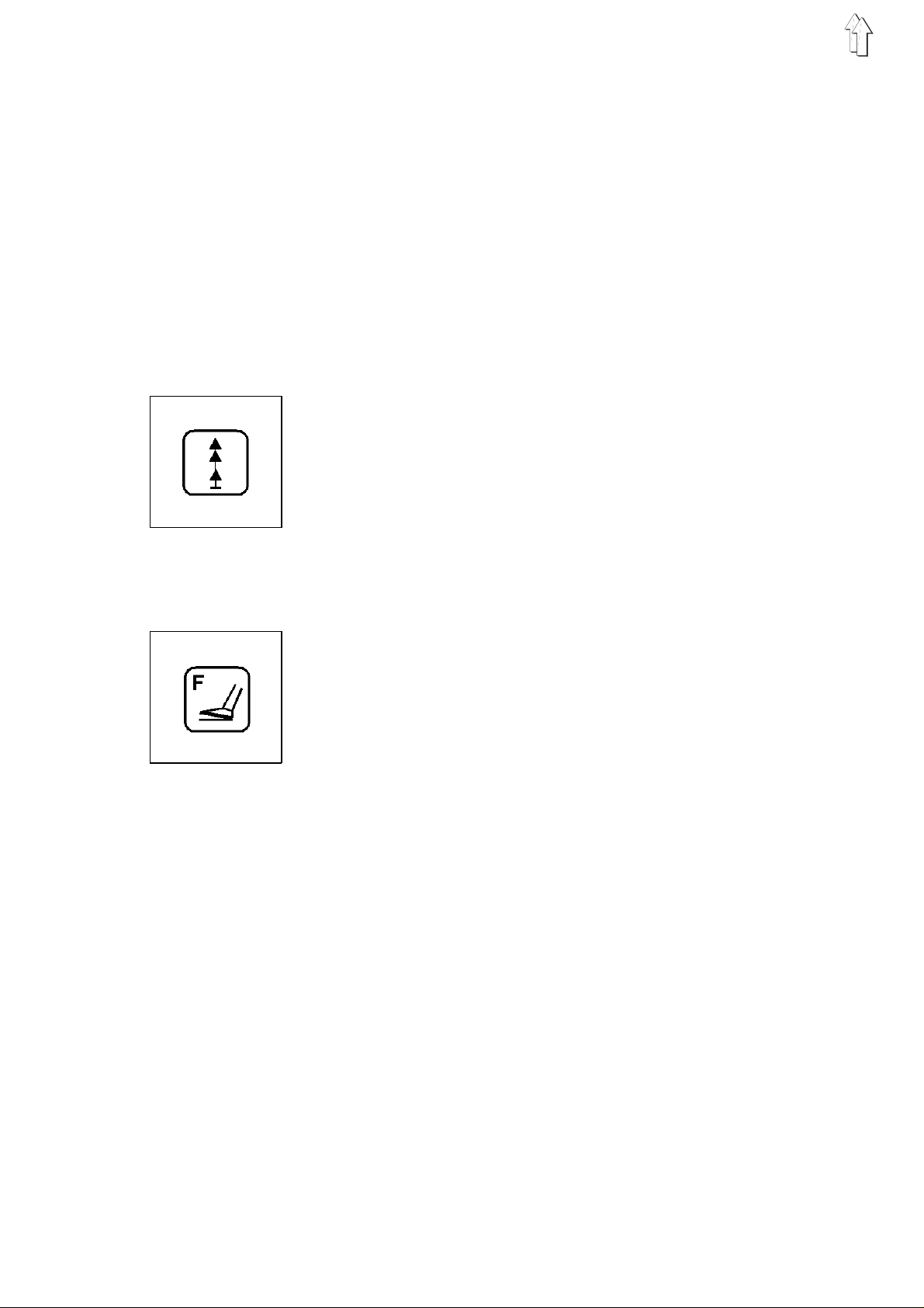
3.1 Softstart
With the softstart switched on the first stitches on the seam beginning
are sewn at reduced rpm.
The softstart is turned on and off by operating the key.
The softstar t i s ac t i v e w he n t he LE D above the key is l i t.
+ / -
" - keys.
3.2 Foot Switch Mode
Two different foot switc h mo de s are av a i l ab l e.
–
Set the desired foot switch mode with the "+/-" keys.
Mode 1
–
–
–
Mode 2
–
–
–
–
(Display:
After the first operation of the right fo ot switch both clamps are
lowered together.
With the clam ps l o we red th e s e win g s e qu en c e is s t art ed by
operating the l ef t f oo t s w i tc h .
With the sec o nd op er a ti o n o f t he r i gh t f oo t s w i tc h bo th c l am ps a re
raised again.
(Display:
Through operation of the left foot switch the left clamp is lowered.
Through opera tio n o f t he r i gh t f oo t sw i tc h th e l o we ri ng of th e ri g ht
clamp occurs.
As long as only one clamp is lowered this can be raised again by a
second opera ti o n o f t he ap pr o pr ia t e fo ot s wi t c h.
If both clamps are already lowered the sewing sequence is started
by operating th e l e ft fo ot s wi t c h.
F=01
F=02
)
)
7
3.3 Burner Sett ings
Two different types of bu rne r op era t io n are available :
–
with preheatin g
–
without preheating
If the sewing t i me ne ces sa r y fo r th e s e am fo rma ti o n is s h ort er t ha n t he
heating tim e re qu i r ed by the burner the co nt r ol s automatically s w i tc h
over to "wit h p r eh ea ti n g" .
With aid of th e preheating the bu rne r i s pre he at ed to a specific ba s e
temperature. T hi s r e du c es the time requir ed fo r he at i ng to the
operating tem perature.
The sewing ti m e r e qu i red i s de pe nd en t o n t he number of stitch es p er
curve disk revolution and the selected rpm.
With preheating
–
In the first line of the display the symbol "*" appears in fro nt of the
machine head rpm.
–
Press the key.
"G" blinks in the display.
–
Set the period for the preheating with the "
period, 10 = longest period).
Without preheating
–
Press the key.
"B" blinks in the display.
–
Set the time for tu rni n g o n t he th rea d b urn er w ith th e "
(1 = earliest switch-on time, 10 = latest switch-on time).
Note:
The earliest switch-on time means a longer glowing period.
–
Press the key again.
"E" blinks in the display.
–
Set the switch-off time of the thread burner with the "
(1 = shortest period switched on, 10 = longest period switched on).
+ / -
" keys ( 1 = shortest
+ / -
+ / -
" - keys
" - keys
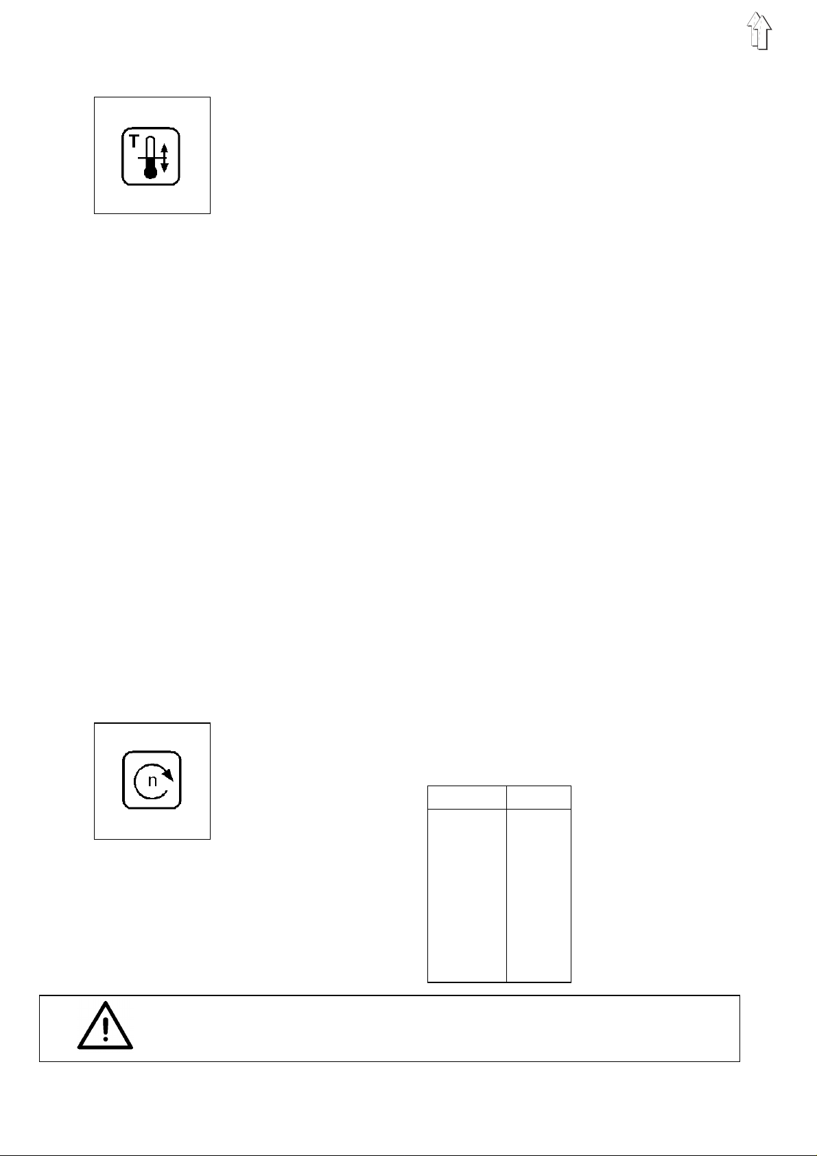
3.4 Machine Head R pm
With the aid of this key the machine head rpm can be set.
The rpms which can be set can be found in the table below.
–
Set the desir e d rpm with the "
Rpm [1/min]
Attention!
At plans with a middle to large zig-zag-stitch the machine head rpm
must be lowered to a adequate level.
+ / -
" - keys.
1400
2500
3600
4700
5800
6900
71000
81100
8

3.5 Bobbin Change
Caution Risk of Injury !
Turn the main switch off.
Change the bobbi n on l y wi t h t he ma i n switch turned off.
–
Press the " " key.
The machine head positions in position 3.
The bobbin ca n b e c h an ge d.
Note:
For better accessibility by the seamstress there is a second alternative
key on the left side of the head cover of the unit.
3.6 Resetting the Counter for the Bobbin Winder
If the windi ng procedure is int err u pt ed pr e ma tu r el y m an ually the
counter must be reset as follows:
–
Turn the main switch off.
–
Turn the main switc h on an d at the same time pr e ss th e " " k e y.
The counter is reset to the beginning value set in program P41.
–
As long as t he k ey is o pe r at ed "
SP-RESET
" appears in the display.
3.7 Resetting the Piece Counter
The piece counter is reset to zero with this key.
The piece counter shows the number of pieces sewn since the last
resetting of th e c o un te r.
The production counter cannot be reset !
9

4. Calling Up the Sewing, Service and T esting Programs
The sewing, service and testing programs listed below are selected
with the "
Switch Setting Program Function
00 P00 Displays t he program version
01 P01 Sewing progr a m
02 P02 Sewing program with intermediate stop after 50% of the stitches
03 P03 Sewing program with intermediate stop after 50% of the stitches
11 P11 Sewing progr a m w i th th e r p m ranges programme d i n P 41
40 P40 Setting the number of bartacks per bobbin
41 P41 Program used to set the progra mm ab l e r p m ranges used
42 P42 Burner test : g l ow i ng
43 P43 Burner test: lo we r ing an d g l ow i ng
44 P44 Burner test: lo we r ing i n s t ag es
45 P45 Burner test: slow sewing, lowering in stages
Program
and opening o f t he r ight half of the cl a mp
and opening of the left half of the clamp
in P11
" selector switch.
58 P58 Checking the serial interface
59 P59 Timer test and memory test
60 P60 Continuity t est
61 P61 Checking the front panel elements
62 P62 Checking the input elements
63 P63 Selecting i n pu t e l em en ts
64 P64 Selecting output elements
66 P66 Sewing driv e : rpm test, posit i on 2
67 P67 Sewing driv e : rpm test, posit i on 1
68 P68 Sewing driv e : rpm test, posit i on 1, po s iti o n 2
–
Set the "
–
Turn the main switch on or press the "
The select ed pro gr a m i s a cti v a te d.
–
If the symbol "P?" appears in th e ri ght half of the fi r s t l i ne of th e
display an i nv a l i d p rogram number was s e t.
A sewing sequence running at the time the "
pressed will be interrupted.
–
Correct the se tt ing an d p r ess t he "
Program
" switch to the desired program.
STOP
" key.
STOP
STOP
" key.
" key was
10

5. Base Position and Operational Readiness
Base position
–
Turn the main switch on.
–
The microcomputer checks the base position of the unit.
–
When findin g a n error this is shown by the appr op ri at e s y m bo l i n
the display.
The unit can n ot be s ta r te d.
–
Correct the error.
If the display shows "
position manually with the handwheel.
–
Turn the main switc h off and on again or pre s s th e "
The base posi t i on of th e u ni t i s che c k ed ag ai n .
–
After the unit is turned on the note "
right half of th e f i r s t li n e o f the display:
–
Press the "Σ" key.
The machine head runs into the unit’s base position.
Operational re adi n es s
The sewing sequence can only be started when the unit is in
operational r ea di n ess .
Operational readiness is signaled by the display of the piece count in
the right half of the first line of the display.
Before the st ar t of a s e wi n g s e qu en c e t he mi cr o c om pu te r pe rma ne ntly
checks the momentary positions of the devices.
Errors found are shown in the display.
POS2
" the unit mu st b e turned into the 2n d
REFERENZ->
Σ" ap pe ars i n th e
STOP
" key.
11

6. Sewing Programs
6.1 Sewing Program P01
6.2 Sewing Program P02
The exact wor k s e qu en c e o f t he s ewing program P0 1 i s d esc r ibed in
the Operatin g I ns t r uct i on s .
–
Set the "
–
Press the "
The program i s ac t i vated.
–
With the preheating of the burner switched on the symbol "*"
appears in the right half of the first line of the display in front of the
value for the machine head rpm.
With low machine head rpms the preheating is automatically
turned off. The "*" symbol di sa pp ears.
Program
STOP
" switch to "01".
" key.
6.3 Sewing Program P03
–
Set the "
–
Press the "
The program i s ac t i vated.
Difference to P01:
–
After complet i ng 50 % o f t he nu mb er o f s t i tch es t he s ew i ng dri ve
stops in position 2.
The right ha l f o f t he c l am p i s r a i s ed .
In this posi t i on , f or e x am pl e , l a bles to be sewn in to th e m at er i a l
can be aligned.
–
Operate the r i gh t f oo t s w i tc h .
The right hal f o f t he cl am p i s lo we r ed .
Through renewed operation of the right foot switch the right half of
the clamp ca n b e r a i sed again.
–
With the right ha l f o f t he c lam p l o we red op er a te th e l e ft fo ot sw it c h.
The sewing s e qu en c e is s t ar t ed ag ai n .
–
Set the "
–
Press the "
The program i s ac t i vated.
Program
STOP
Program
STOP
" switch to "02".
" key.
" switch to "03".
" key.
12
Difference to P02:
–
At the intermediate stop in position 2 the left half of the clamp is
raised.

6.4 Sewing Program P1 1
–
Set the "
–
Press the "
The program is activated.
Difference to P01:
–
The constant machine head rpm selected for the entire seam
before starting work is replaced by rpm ranges which are
programmed i n t he
This makes it possible to adjust the speed profile individually to the
seam pattern. The current machine head rpm is shown in the
display, and is also tag ge d w i th a p r ec e ding symbol for th e
variable machine head rpm.
–
Pressing th e "n" key to set th e m ac h i ne he ad rpm has no effect in
this program.
–
Altering t he nu mb er o f s t i tc h es p er c a m-d i s c rev o l ut i on
automatical l y era s es t he pr o gra mm ed rpm ranges for th e o l d
number of sti tc h es .
The number of stitches of the cam-disc is displayed with a
preceding "?".
–
Press the "Σ" key to leave this display.
–
The "=> P41 !" prompt appears.
This is to re mi n d t he us e r that the
program new rpm ranges.
–
Turn t he "
–
Press the "
Program 41 i s ac t i v at ed ( see s ec t i on 7. 2)
Program
STOP
Program
STOP
" switch to "11".
" key.
P41
setting prog r am .
" switch to "41"
" key.
P41
program must be used to
13

7. Service Programs
7.1 Setting the Underthread Counter
Program P40 sets the number of pieces which can be sewn per bobbin.
–
Set the "
–
Press the "
The program i s ac t i vated.
In the display, next to the bobbin symbol, the set value appears.
–
Set the desired value with the "
(input = e.g. 0020)
–
The cursor can be moved to different positions with the "Σ" key.
7.2 Programming vari able rpm r anges
Up to 6 different r p m r a ng es c a n b e p r og r am me d i n P rog r am P4 1. The
programmed rpm ranges are only execut ed in sewing program P11.
–
Set the "
–
Press the "
The program i s ac t i vated.
Programmin g rp m r a ng es ca n be carried out i n tw o d i ffer en t w ay s :
–
Programmin g in s i ng l e-s t i tc h mo de .
The display is as follows: S+1 +> Sx-Sy
This proces s s h ou l d b e u s ed i f n o r p m ra nges have yet been
assigned to th e s e am pa tt er n .
–
Programming in range-specifying mode.
The display is as follows: S+1 <+ Sx-Sy
This proces s s h ou l d b e u s ed i f r p m ra ng es h av e al ready been
assigned to th e s e am pa tt er n .
Program
STOP
Program
STOP
" switch to "40".
" key.
" switch to "41".
" key.
+ / -
" - keys.
Press the "+" key to toggle between the two modes.
–
Press the "Σ" key to invoke the selected programming mode.
Programming in single-stitch mode
Setting the first rpm range
–
The machine head rpm "n" flashes in the display.
Set the required initial value for the machine head rpm with the
+/-
"
" keys.
Caution Risk of Injury !
Do not reach into the ma chine while it is in operation.
–
Press the "Σ" key and hold it down until the number of completed
stitches a ft er w hi c h a n ew ma c hi n e h ea d r p m i s t o take effect
appears in the display. As long as the "Σ" key is held down the
stitches are executed and the number of completed stitches is
increased.
As soon as t he " Σ" key is released the machine head rpm set is
saved for th e ra nge in question .
14

Setting the second rpm range, at maximum up to the sixth one
–
The machine he ad r pm " n" flashes in the d i s pl a y.
Set the required initial value for the machine head rpm with the
+/-
"
" keys.
–
Press the "Σ" key a nd ho l d i t do wn un ti l t he nu mb er o f c o mp l et ed
stitches after which a new machine head rpm is to take effect
appears in the display. As long as the "Σ" key is held down the
stitches are ex e c ut ed an d the number of co mp l et ed s titches is
increased.
As soon as the "Σ" key is released the machine head rpm set is
saved for the range in question.
–
When the in dic a te d s t i tc h nu mb er (S ) is r e ac h ed , t he
previously-programmed rpm ranges are saved.
There is then an automatic return to the start of program
Attention:
If the value of the currently co nducted indivi du al s t i tc h es i s l e s s
than "4" or greater than/equal to the result of "number of stitches-2",
then no new machine head speed "n" can be set with the aid of the
+/-
"
" keys. Thes e v al u es are indicated i n th at th ey ar e shown blinking
in the display and the machine head speed does
Programming in range-specifying mode
not
blink.
P41
.
ATTENTION!
In order to ensure trouble-free operation in sewing program P11,
programming must always encompass the entire stitch-number range.
Setting the first rpm range:
–
The cursor f l ashes in the termi na l v al u e o f t he s ti t c h-n um ber range.
The cursor can be moved with the "Σ" key.
The value at t he c urs o r po s iti o n c a n b e c h an ge d with the "
–
Once the required terminal value of the stitch-number range has
been set, sw i tch to rpm setting by pr e s si ng th e "n" key.
The machine head rpm "n" flashes in the display.
Set the machine head rpm with the "
–
Confirm th e rp m r a ng e s e t b y pre s s ing the "Σ" key.
–
The terminal value of the rpm range is increased by one to form
the starting v al u e o f t he ne x t r p m ra ng e.
Setting the second to sixth rpm ranges:
–
These are pro gr a mm ed i n t he s am e w ay a s th e f i rs t r p m ra nge.
–
Care must be taken that the terminal value of each stitch-number
range is between the starting value and the highest stitch number.
–
Input is termi n at ed wh en th e h i gh est s ti t c h num be r is en te r ed as a
terminal value.
There is then an automatic return to the start of program
+/-
" keys.
+/-
P41
" keys.
.
Attention:
If the final value of the stitch number range is less than "4" or greater
than/equal t o t he r esu l t o f "n umber of stitche s - 2", then no new
machine head s p ee d " n " c an be s et wi t h t he ai d of th e "
In the first c a se no change over to th e s p ee d s e tt i ng oc o ur s a fter the
"n" key is oper at ed . I ns t ea d, the value "
as the final v a l ue of th e s t i tc h nu mb er ra ng e. In the second cas e t he r e
is also no change over to the speed setting after the "n" key is
operated. Instead, the "number of stitches" is shown in the display as
the final value of the stitch number range.
0004
" is shown in the display
+/-
" keys.
15

7.3 Burner Test: Glowing
Caution Risk of Injury !
Danger of Burns !
During the burner test keep hands clear of the area of the glowing
burner.
–
Set the "
–
Press the "
The program i s ac t i vated.
–
B-TEST->
"
display.
The set number of stitches per curve disk revolution (e.g. S = 72)
appears in the right half of the first line of the display .
–
Press the "Σ" key.
The burner is t ur n ed on fo r a sh or t pe r i od .
7.4 Burner Test: Lowering and Glowing
Caution Risk of Injury !
Danger of Burns !
During the burner test keep hands clear of the area of the glowing
burner.
–
Set the "
–
Press the "
The program i s ac t i vated.
–
B-TEST->
"
display.
In the right h al f of the first lin e o f t he di s p l ay t he s et nu mb er o f
stitches per curve disk revolution (e.g. S = 72) appears.
–
Press the "Σ" key.
The burner is t ur n ed on .
A sequence as at the seam end is run through.
Program
STOP
Σ" appears in the right half of the second line of the
Program
STOP
Σ" appears in the right half of the second line of the
" switch to "42".
" key.
" switch to "43".
" key.
7.5 Burner Test: Lowering in Stage s
–
Set the "
–
Press the "
The program i s ac t i vated.
–
B-TEST->
"
display.
In the right h al f of the first lin e o f t he di s p l ay t he s et nu mb er o f
stitches per curve disk revolution (e.g. S = 72) appears.
–
Press the "Σ" key repeatedly.
With each operation of the key the sequence as at the seam end is
run through i n s ta ge s .
The burner re ma i ns sh ut off hereby.
16
Program
STOP
Σ" appears in the right half of the second line of the
" switch to "44".
" key.

7.6 Burner T est: Slow Sewing, Lowering i n Stages
–
Set the "
–
Press the "
The program is activated.
–
B-TEST->
"
display.
In the right half of the first line of the display the set number of
stitches per curve disk revolution (e.g. S = 72)appears.
–
Press the "Σ" key.
The unit sews slowly to the seam end.
–
Press the "Σ" repeatedly.
With each ope r at i on of th e k e y th e s e qu en c e a s at the seam end is
run through in stag es (see program P44).
The burner remains shut off hereby.
Program
STOP
Σ" ap pe ars i n th e ri g ht half of the sec o nd l i ne of th e
" switch to "45".
" key.
17

8. T esting Programs
8.1 Displaying the Program V e rsion and Check Sum
The display shows in succession the program version and a check
sum.
e.g.:
By program versions with the same class designation and the same
identification letter the higher version replaces all lower versions
(Example: 506V03 replaces 506V01 and 506V02).
The check sum is meant only for the factory service staff.
It allows ex pe r ts to see if the prog r am me mo r y (E P RO M ) of the unit
controls flawlessly contains the complete program.
Dürkopp Adler AG
506A01 5C A9
506 = Class desi gn at ion of th e u ni t
A01 = Identif ic at i on l et te r an d s e ri al n um be r
5CA9= Check sum
–
–
8.2 Checking the Serial Interface
Program P58 checks the SIO component of the controls.
–
–
–
Display Explanation
OK
Err
no SIO
Set the "
Press the "
The program i s ac t i vated.
Plug the SIO testing plug into the socket b109 on the main board.
The testing pl u g c o nn ect s th e t ran s mi t te r wi t h t he rec e i ver.
In this man ne r a t es t of the loop is poss i bl e .
Set the "
Press the "
The program i s ac t i vated.
Program
STOP
Program
STOP
" switch to "00".
" key.
" switch to "58".
" key.
SIO componen t i s o k ay
SIO componen t i s d ef ec t i ve,
SIO testing plug is not in place
Controls are b ein g r u n w i th ou t S I O
18

8.3 Memory Test and Timer Test
ATTENTION !
Program P59 erases all values in the memory!
All values must be reset.
Program P59 checks the working memory (RAM) and all timer
switchings of the controls.
8.4 Continuity T est
–
Set the "
–
Press the "
The program is activated.
Display Explanation
OK
ERROR 0
ERROR 6
ERROR 7
Program P60 checks if the 24V power supply delivers current with the
output drive r s s wi t c he d o ff.
Program P60 checks all output elements (including output drivers and
installation) for continuity.
–
Set the "
–
Press the "
The program is activated.
Program
STOP
Program
STOP
" switch to "59".
" key.
Working memory and all timer switchings
are okay
RAM error
Timer 1 defective
Timer 2 defective
" switch to "60".
" key.
Display Explanation
V?
OK
s17
(Example) installation or driver
Short circuit in the installation or
one of the output drivers is defective
All circuits have continuity
Interruption in the output element s17, in its
Output eleme nt s17 does not ex is t be c au s e i t i s part
of the special optional equipment
Continue th e t es t i ng at th e n ex t el e me nt
by pressing th e "Σ" key.
19

8.5 Checking the Front Panel Elements
Program P61 checks the front panel elements.
–
–
–
Key Function
b513/512 Program switch
b829 Softstart on/off
b828 Foot switch mode, lowe r cl am ps
b825 Bobbin change
b826 Machine head rpm
b827 Burning period correction
b500 Number of stitches per curve disk revolution
8.6 Checking the Input Elements
Program P62 checks the switching status of the input elemen ts.
Set the "
Press the "
The program i s ac t i vated.
Press the key to be checked.
The display shows the value assigned to this switch.
Program
STOP
" switch to "61".
" key.
(together or individually)
–
Set the "
–
Press the "
The program i s ac t i vated.
–
Press the input element to be checked.
The display shows the wiring diagram designation and the
switching status of the input elements (e.g. "+b25").
–
The display c h an ge s wh en th e s w i tc h i ng s ta tu s of an y ot he r input
element is c h an ge d.
The switching status "+" means:
–
By contact switch = Contact open
–
By proximity switches = Metal in front of the switch
The following switches cannot be checked with program P62:
–
b101 Head cove r mo ni t or ( S t op )
Program
STOP
" switch to "62".
" key.
20

8.7 Selecting Input Elements
ATTENTION !
All input elements were carefully set at the factory.
Adjustments and corrections may only be made by trained service staff.
Program P63 ser v e s for the setting of the input elem en ts .
–
Set the "
–
Press the "
The program is activated.
The display shows "B?".
–
Set the "
element.
The short designations of the circuit diagram serve as code
numbers (see table). This does not apply for the keys on the front
panel (see Chap te r 7. 5).
The display s h ow s th e wiring diagra m d es ig nation and the
switching status of the input element (e.g. "
–
Adjust the i n pu t e l em en t ( e .g . p r oxi m i ty s w i tc h ) un ti l t he de s i r ed
switching s t at us i s s h own in the displa y ( see program P 62).
Input Function
Element
b09 R ear transport lever in the base position
b10 Base position Stop
b12 R ight clamp up
b16 Forward transport lever in the base position
b17 Left clamp up
b18 Foot switch right
b20 Foot switch left
b23 Bobbin change
b35 Synchronizer position 1 (needle down)
b37 Synchronizer position 2 (needle up)
b38 Synchronizer position 3
Program
STOP
Program
" switch to "63".
" key.
" switch to the code number of the desired input
(needle mov i ng fro m down to up)
+B25
").
The following switches cannot be checked with program P63:
–
b101 Head cover monitor (Stop)
21

8.8 Selecting Out put Element s
Caution Risk of Injury !
During the function testing of the output elements do not reach into the
running machine, especially not under the clamps.
Program P64 checks the function of the output elements.
–
Set the "
–
Press the "
The program i s ac t i vated.
The display shows "S?".
–
Set the "
element.
The short de si gn ations of the cir c u it diagram serve as c o de
numbers (see table).
–
Turn the selected ou tp ut el e me nt on and off by press i ng th e
"Σ" key in tapping operation.
Output Function
Element
s01 Lower left clamp
s02 Lower right clamp
s03 Open thread tension
s04 Pull thread
s18 Needle cooling
s19 Transport lever forward
s20 Thread wiper forward
s22 Lower burner
s26 Burner forward
s28 Hook lubrication
Program
STOP
Program
" switch to "64".
" key.
" switch to th e c o de nu mb er o f t he de s i r ed input
22

8.9 Sewing Drive: Rpm Test, Position 2
Program P66 serves for testing the different rpms of the sewing drive.
Different rpms can be selected with th e "
Program
" switch.
–
Set the "
–
Press the "
The program is activated.
The display shows "
–
Press the "Σ" key.
–
Select the rp m o f t he s ew i ng dri ve wi t h t he "
A total of 13 rpm levels are available.
Switch setting "13": Maximum rpm
Switch setting "01": Minimum rpm
–
With an allowable value "
line of the di spl a y, with an unallo wa bl e v alu e "
–
Press the "Σ" key and hold.
The sewing dr iv e r un s at th e s e l ect ed rpm.
After a few seconds the current rpm (actual rpm of the machine
head) is sho wn i n t he r igh t half of the fir st l i n e o f t he display.
–
Release th e " Σ" key.
The sewing un i t p os i t i on s in p os i t i on 2 ( t hre ad lever high pos i t i on ).
8.10 Sewing Drive: Rpm Test, Position 1
–
Set the "
–
Press the "
The program is activated.
The display shows "
Program
STOP
Program
STOP
" switch to "66".
" key.
N-TEST->
" switch to "67".
" key.
N-TEST->
Σ".
0000
" appears in th e ri g ht ha l f o f t he fi rs t
Σ".
Program
SW?
" appears.
" switch.
Difference to program P66:
–
After releasing the "Σ" key the sewing unit positions in position 1
(thread lever l o w p osi t i on ).
8.11 Sewing Drive: Rpm Test, Position 1, Position 2
–
Set the "
–
Press the "
The program is activated.
The display shows "
Difference to program P66:
–
After rele ase of the "Σ" key the sewing unit stops fo r a b r i ef pe ri od
in position 1 ( t hre ad l ev e r low position).
–
Then the sewing unit positions in position 2 (thread lever high
position).
Program
STOP
" switch to "68".
" key.
N-TEST->
Σ".
23

9. Function Displays and Error Messages
9.1 Displays of Operating Aids
Display Explanation Remedy
P?
506B01
REFERENZ->Σ
STZ-ERR
H->
B-TEST->Σ
N-TEST->Σ
UNTFVZ-RESET
S+1 <+> Sx-Sy
Invalid program selected
Display of the program version
Machine head must co nduct a re ferenc e run
The "number of stitches" (b500) switch
in an invalid switch setting
Underthread bob bi n em pt y
Activate th e t es t pr o gra m f or t he bu r ne r
Activate the test i ng pro gram f or rp m
Underthread co un te r r ese t
Selection between single-stitch
operation (S +1 ) or ra ng e s e tt i ng ( S x- S y )
for the requi red r pm s ection
9.2 Displays of Malfunctions
Display Explanation Remedy
E2
V?
STOP
--<>-POS2
POS2->Σ
STRT-ERR
KL-ERR
TIME
GRUNDST
TR-ERR
STICHZAHL-ERR.
TAB.-OV
=> P 41 !
Fuse e2 in the transformer (24V)
defective
Error message in program P60
STOP key defective,
Termination of the sewing sequence
Synchronizer not plugged in
Needle not in t he up pe r po s i tio n
Needle not in t he up pe r po s i tio n
Short in the switch lead at the
foot switch,
Foot switch was already operated when
the main switch was turned on
Incorrect clamp lowering
Sewing driv e do es n ot s to p q ui ck l y
enough
Machine not i n t he base position
Incorrect transport lever operation
Stitch-num be r ran ge s et i s to o s m all
Table for a maximum of 6 rpm ranges
exceeded.
No rpm ranges programmed
Reset the "
Press the "Σ" key
Reset the "number of stitches" (b500)
switch
Change the bobbin
Press the "Σ" key
Press the "Σ" key
Replace fuse e2
See Chapter 5. 6 (" Co nt i nu i ty Test")
Replace STOP key
Plug in the synchronizer
Turn the needle into the upper position
with the handwheel
Press the "Σ" key
Check the le ad
Release the foot switch, press the STOP
key
Check switches b12, b17 and movement
of the clamps
In program P66 check if motor and
controls function correctly
Reset switch b10
Carry out programming in P41
Program
" switch
24

9.3 Error Messages
Display Explanation Remedy
PROM-ERR
RAM-ERR
DISP-ERR
Faulty EPROM check sum when turning
on
Faulty RAM tes t wh en tu r ni n g o n
Display error when turning on
Program not correctly stored in memory
Call factory service
ERROR 0
ERROR 1
ERROR 2
ERROR 3
ERROR 4
ERROR 5
ERROR 6
ERROR 7
ERR Bxx
no SIO
ERR
RAM error
Error in the i n pu t e l em en ts
Error in the f r on t p an el e l em en ts
Program switch defective
Regulator card for the sewing drive defective
Short voltage drops in the mains
Timer 1 defective
Timer 2 defective
Error in rea din g i n pu t element bxx
Controls have no S IO c o mp on en t
Interruption in th e S I O s en d /
receive loop
Call factory service
Check the input elements
Check the front panel elements
Replace the pro gr a m switch
Replace the regulator card
Stabilize the voltage supply
Call factory service
Call factory service
Replace defective switch bxx,
reset switch bxx
Press the STOP key
Press the STOP key
25
 Loading...