

Page 1

Contents Page:
Home
Preface and General Safety Information
Part 1: Operating Instructions Cl. 506
1. Product Description
1.1 Description of the Proper Use and Proper Application . . . . . . . . . . . . . . . . . . . . . . . 5
1.2 Short Description . . . . . . . . . . . . . . . . . . . . . . . . . . . . . . . . . . . . . . . . . . . . 5
1.3 Technical Data . . . . . . . . . . . . . . . . . . . . . . . . . . . . . . . . . . . . . . . . . . . . . 6
2. Operation
2.1 Automatic Sewing Sequence . . . . . . . . . . . . . . . . . . . . . . . . . . . . . . . . . . . . . 7
2.2 Needles and Yarns . . . . . . . . . . . . . . . . . . . . . . . . . . . . . . . . . . . . . . . . . . . 9
2.3 Threading the Needle Thread . . . . . . . . . . . . . . . . . . . . . . . . . . . . . . . . . . . . . 10
2.4 Changing the Bobbin . . . . . . . . . . . . . . . . . . . . . . . . . . . . . . . . . . . . . . . . . 12
2.5 Thread Tension . . . . . . . . . . . . . . . . . . . . . . . . . . . . . . . . . . . . . . . . . . . . . 14
3. Bobbin winder
4. Maintenance
4.1 Cleaning . . . . . . . . . . . . . . . . . . . . . . . . . . . . . . . . . . . . . . . . . . . . . . . . 16
4.2 Lubrication . . . . . . . . . . . . . . . . . . . . . . . . . . . . . . . . . . . . . . . . . . . . . . . 17
. . . . . . . . . . . . . . . . . . . . . . . . . . . . . . . . . . . . . . . . . . . . . 15
Page 2

Page 3

1. Product Description
1.1 Description of the Proper Use and Proper Application
The 506 is a robust, heavy-duty, curve-guided single needle doulble
saddle stitch short seam unit for seams of stitch type 301.
This short seam unit is designed for use in sewing heavy-weight fabric,
as well as thick and hard leather.
Thick and hard leathers find use in the sewing on of trim pieces, in the
sewing of buckle caps, tabs, suitcases, tarpaulins, knapsacks and
backpacks.
Heavy-weig ht fa br ic s a r e u sed i n t he sewing of heav y -d uty carrying
belts, car belts, as well as belts for aviation.
Generally only dry sewing material may be worked with this machine.
The material m ay b e n o t hi ck e r th an 16 mm wh en pre s sed to ge th er b y
the lowered cl am pi n g f ee t.
The machine m us t be op er a te d w i th ey e protection. The information to
be found print ed on the yellow s ign on the head cov er i s t o b e s t r i ctl y
adhered to.
The seam is generally made with synthetic sewing yarns with a
dimension of 30 /3 to 8/3. Those wi s hing to use other th reads must first
evaluate the d angers arising therefrom and, i f n ecessary, take safety
measures.
This heavy short seam unit may only be installed and operated in dry
and clean are as . If th e u ni t i s used in other areas , wh i c h a r e n ot dry
and clean, f urt he r, to be agreed upon, measur es m ay b ec o me
necessary (see EN 60204-3-1:1990).
We, as manufactu r er o f in dustrial sewi ng ma c hi n es , pre s um e t ha t t he
operating personnel working on our products have been given
instruction so that all normal operations and the dangers possibly
arising the ref r om c an be as sumed to be know n.
1.2 Short Description
Uniform Quality
The unit always produces a uniform seam formation.
The high thread tension necessary for the working of heavy materials
is achieved through a hinge d t hr e ad l eve r.
Direct Power Transmis si on
The power transmission from the motor to the arm shaft occurs via a
special V-belt. This results in a particularly strong perforating power
for the sewing of thick materials or multiple layers.
Interchangeable Curve Disks and Material Clamps
The different s ea m f ormations are de te rmi n ed by e as i ly
interchangeable curve disks.
The material guidance occur s vi a a p at t e rn c u r ve with two guide
curves. The difficult and time-consuming turning of heavy pieces of
material by the seamstress is thus unnecessary.
The transmis s i on of th e m ov e me nt to th e m aterial clamps o c cur s vi a
lever systems. By changing the lever multiplication the seam formation
sizes can be varied within certain limits.
All curve disks belonging to a stitch number range are interchangeable
among each ot he r.
Large Put-through Area and Large Placement Surface
The large put-through area allows the making of short seams far from
the edge of the material. A rolling-in of flexible sewing material is
possible. Th e c l o s ed wi d th ba s e p l at e o ffer s a l ar g e pl a cement surface
and simplif i es t he fe ed .
5
Page 4

Pneumatic C la m p O pening
The stroke of the holder clamp is a maximum 20 mm. This stroke allows
the working of almost all sewable materials and leather thicknesses.
1.3 T e chnical D ata
Electric Thread Burning Device
The thread separator device separates the needle and underthread by
burning immediately at the top edge of the material. The synthetic
threads are melted together at the ends. The thus created hardening
hinders a loosening of the seam and a unthreading of the needle thread.
MICROCONTROL Controls
The complete control of the sewing unit occurs via a microcomputer. It
assumes the control tasks, monitors the sewing process and indicates
operator erro r s an d malfunctions .
Sewing area: maximum 60 x 100 mm
Needle system: 428; 428 Serv Nm 250;
794 (for thick s e wi n g m at eri a l on ly )
Needle thickn es s: Nm 120 - Nm 280
depending on th e t y pe of s ew i ng th r ea d
and the sewi ng ma te r ial .
Yarns: Synthetic yarns
Nm 30/3 - 8/3
Bobbin capacity: 23 m with 18/3 yarn
Stitch type: Double saddle stitch type 301
Number of stitches: 1100 / min
Number of sti tc h es p er 42, 58, 72 (wi t ho ut ge ar re du c er )
guide curve revolution: 84, 116, 144 (with gear reducer)
Seam formation 72 stitches in 3.5 sec. or
144 stitches i n 7 s e c.
Looping stro k e: 5 mm
Clamp stroke: max. 20 mm
Sewing mate ri al t hi c kness: max. 16 mm (sewing ma terial pressed
together by the c la mp )
Power: 0.55 kW
Motor rpm: max. 2800 rpm
Operating pressure: 6 bar
Air consumption: approx. 1,2 NL per work cycle
Nominal vol ta ge : 9880 506001 3~380-415 V + N , 5 0 Hz
9880 506002 3~220-240 V, 50 Hz
9880 506003 3~220-240 V, 60 Hz
The unit is supplied with one of the
listed voltage kits appropriate to the
nominal voltage.
Dimensions: (H x W x D) 1720 x 1100 x 736 mm
The listed height dimension applies to
the work heig ht of the frame set a t t he
factory.
Put-through area: 210 x 140 mm
Work height: 760...1060 mm (upper edge of the table
top)
Weight: 160 kg
Noise level Lc: 83 dB (A)
Workstation re l at ed em i s s ion ac c o r din g to DIN 45635-4 8-B - 1
Number of stitc h es : 1. 00 0 m i n-1
Commanding ca m: (Stitches) 116
Sewing cycles: 9,7 s on / 2,0 s off
Sewing mate ri al : 2x g i rdl e ta pe 1,5 mm 1.260 g/m
2
Measuring point to DIN 4895 Part 1
X = 0 mm Y = -400 m Z = 300 mm
6
Page 5
2. Operation
2.1 Automatic Sewing Sequence
1
ATTENTION !
Before commissioning it is essential that the number of stitches per
curve disk revolution be set at the internal DIP switch (b500) of the
controls appropriate to the curve disk used (see Part 4: Short
Description Multicontrol).
The starting of a sewing sequence is only possible with the head cover
and cover 3 for the hook area closed.
If the head cover or cover for the hook area is open all functions of the
controls are blocked.
2
3
4
5
Work procedure
–
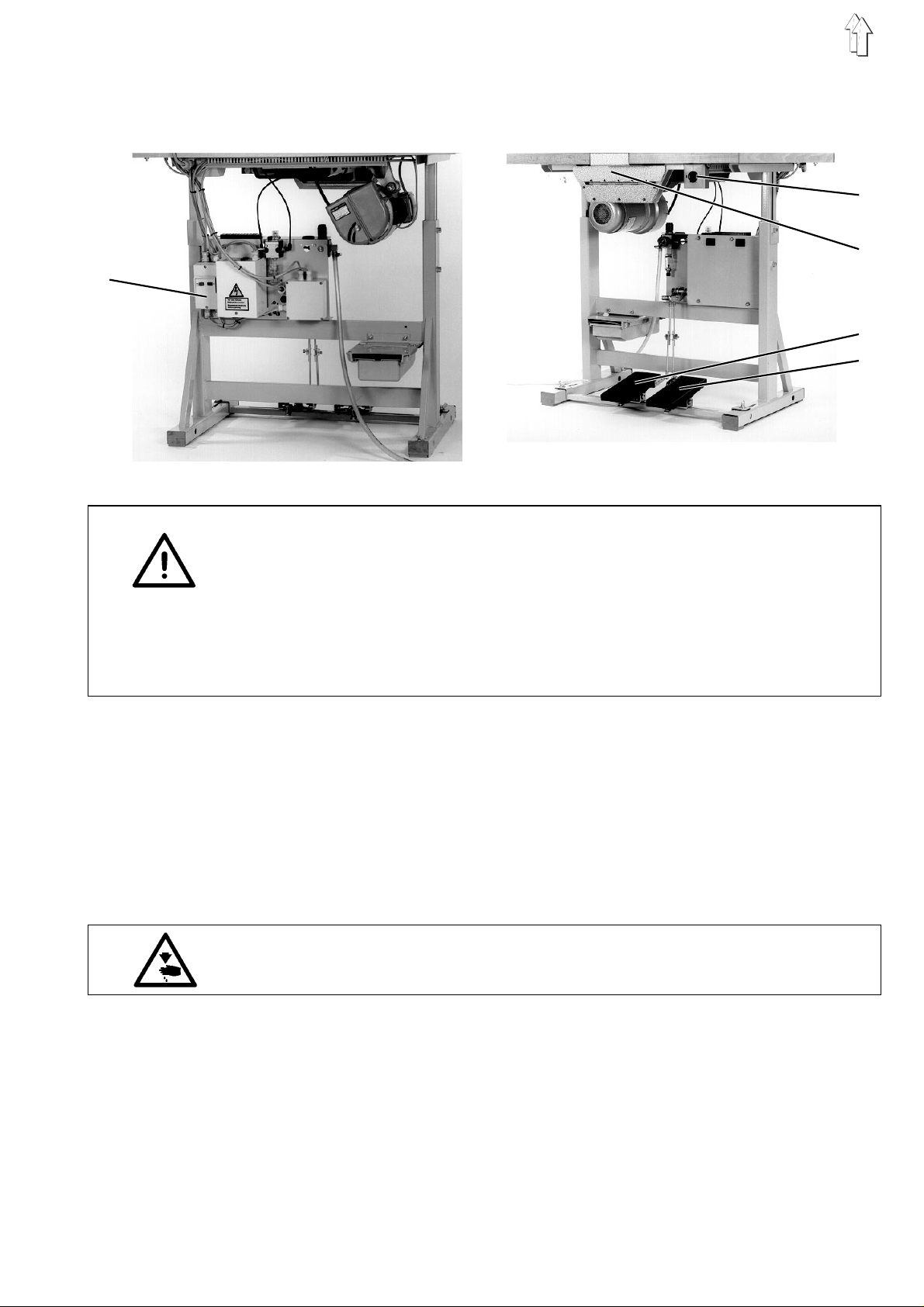
Turn on the motor protection switch 1 under the table top.
It normally remains turned on constantly.
–
Turn the main switch 2 on.
The clamps are in their upper position.
–
Select sew i ng pr o gra m.
–
Align the s ew i ng ma terial under the c l am ps .
Depending on th e t y pe of wo rk s eq uenc e th i s c an oc cu r acc o rdi n g
to the markin gs o r th e s t op s mo un te d s p ec i f i cal l y f or t he c ust omer.
Caution Risk of Injury !
Keep hands free of th e l o we ri ng c lam ps .
–
Operate the right foot switch 5.
Both clamps lower simultaniously.
–
Check the co r rec t al i g nm en t o f the sewing mate r i al.
To correct the sewing material alignment operate the right foot
switch again.
Both clamps rise.
–
Operate the le ft fo ot s witch 4.
The automatic sewing sequence starts.
(in foot swi tc h mo de 1)
7
Page 6
–
For a secure sewing-on draw th e t hre ad end hanging out of the
needle taut to th e s i d e w he n s t ar t i ng th e
and hold tight.
After the fi r s t st i tc h es t he th r ea d c a n b e re l ea s ed ag ai n .
–
The automatic s e wi n g se qu en c e ru ns t hro ug h a c cor d i ng to th e
selected s ew i ng pr o gra m ( P 0 1 - P 0 3) .
For an exact d es c ri p ti o n o f the different sew i ng programs see Par t
4 "Short Description Multicontrol".
–
After the sewing sequence en ds the clamps are r a i sed
automatically.
–
Remove the sew i ng ma te ri al.
Quick stop
first
sewing sequence
1
2
The safety system of the 506 has two different options for the
immediate sh ut - off of th e unit by operat or e r ror, needle bre ak a ge ,
thread breakage etc.:
–
Pressing the
The sewing se qu en ce i s in te r rup te d.
The thread l ev e r mo v es t o t he hi g h p os i t i on .
–
Pressing the
The sewing se qu en ce i s in te r rup te d.
The thread l ev e r mo v es t o t he hi g h p os i t i on .
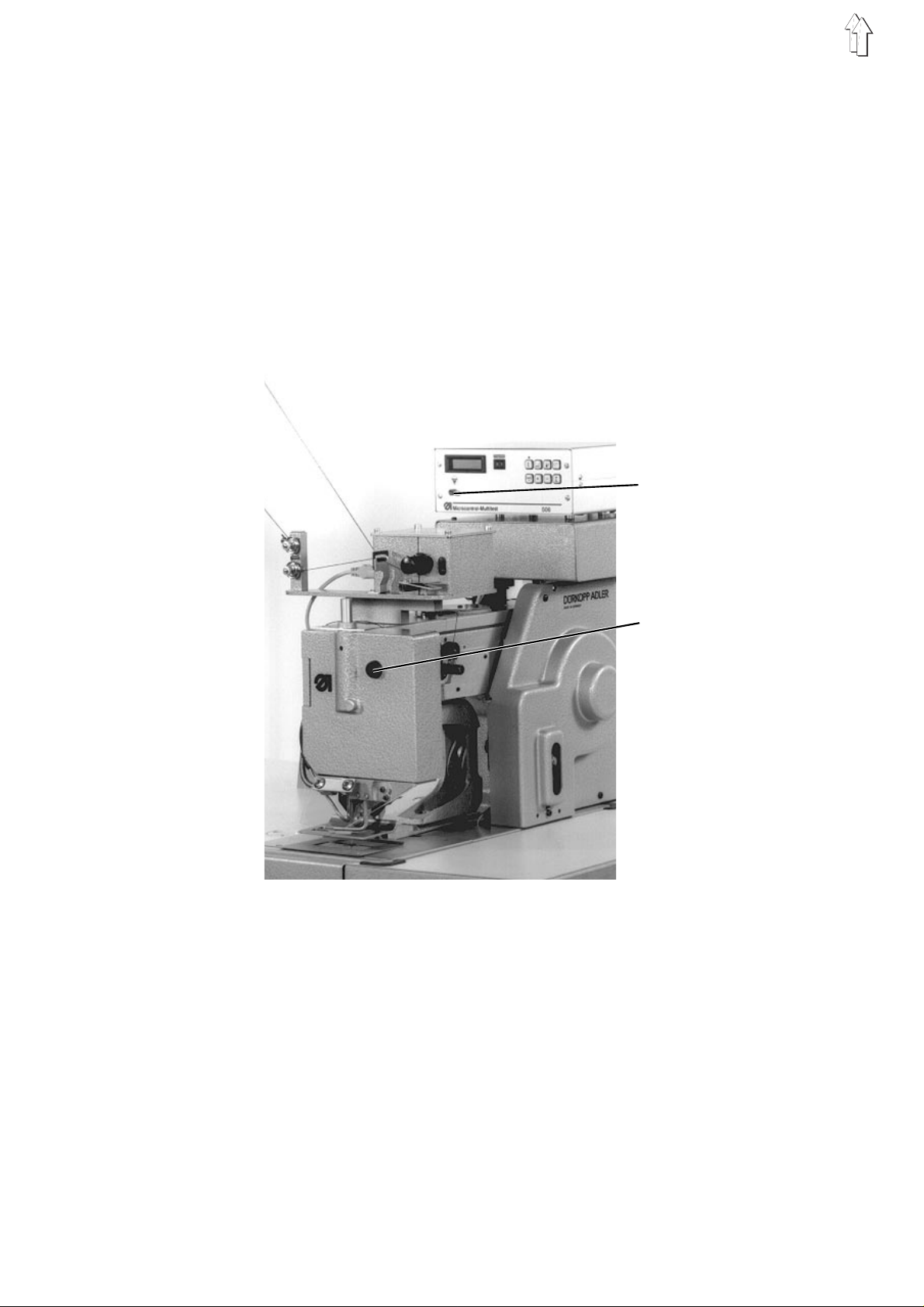
Stop
key 1 on the front panel of the controls.
Stop
key 2 on the head cover.
To continue the sewing sequence:
–
Operate the left foot switch.
8
Page 7

2.2 Needles and Yarns
Needle system: 428; 428 Serv Nm 250; 794
(depending on the type of sewing thread and sewing
material used)
Needle thickness: Nm 120 - Nm 280
(depending on the type of sewing thread and sewing
material used)
Yarns: Synthetic sewing yarns (30/3 to 8/3)
Changing the needle:
2 3
1
A
A
A-A
Caution Risk of Injury !
Turn the main switch off.
Change the needl e on l y wi t h t he un i t t urn ed off.
–
Open the hea d co v er.
–
Loosen screw 1.
–
Remove the needle.
–
Push the new n ee dle i nt o t he ho l e in th e n ee dl e ba r up to th e s t op .
Hereby align t he ne ed l e w i th th e f urro w 3 to th e h oo k .
The furrow 2 must show to the front (to the seamstress).
–
Tighten screw 1.
Attention Danger of Breakage!
After a change to a needle with a different needle thickness it is
essential to check the clearances
driver-needle
If neccessary reset the clearances (see Part 3: Service Instructions).
.
hook point-needle
and
9
Page 8

2.3 Threading the Needle Thread
Caution Risk of Injury !
Turn the main switch off.
Thread the needle thread only with the unit turned off.
The threadin g o f t he ne ed l e t hr e ad oc c u rs as sh own in the pictu r es
alongside i n i n c rea s i ng nu me r ic al o r de r:
–
–
–
–
–
–
–
–
–
–
–
–
–
–
–
–
Place the ya rn r o l l on th e y a rn s t an d.
Thread the thread through the holes 1 of the yarn stand.
Thread the thread through thread guide 2.
Lead the thread through between the tension disks of the first
needle thread tension 3.
Thread the thread consecutively through thread guides 4 and 5.
Guide the thread through between the tension disks of the second
needle thread tension 6.
Thread the thread consecutively through the hole in the thread pull
7 and thread gu ide 8.
Wind the thre ad fr o m t he bo tt om approx. two ti m es a rou nd the
thread roller 9.
Guide the thread through the thread controller spring 10.
Guide the thread under the thread guide 12.
Open the head cover.
Thread the thread through the hole in the thread lever 13.
Guide the thr ea d t hr o ug h t he ho l e i n th e t hr e ad c on trol plate 14.
Insert the thread from the side into the thread gripper 15.
Thread the thr e ad th rou gh the thread gui de 17 on th e n ee dl e ba r.
Thread the thr e ad fro m the front to the b ac k t hro ugh the eye of the
needle.
10
1
Page 9

76542312 10 9 8 7 6 5 4 2 3765423
13
14
15
17
11
Page 10

2.4 Changing the Bobbin
1 2 3 4 5
Remove the empty bobbin
–
Press the " " key.
For better accessability by the seamstress a second key with the
same functi on i s to be fo un d a t the left on the he ad cov e r.
–
Hold the cover 4 and push the arresting lever 1 up to unlock the
cover.
–
Tilt cover 4 to the front.
ATTENTION !
Cover 4 is moni t ore d b y th e sa fe ty s w i tch 5.
With the cov er open all funct i on s of the controls a r e b l oc ke d.
Starting the s ew i ng s eq ue nc e af te r a c h an ge of bo bb i n i s o nly p os s i b le
with the cover closed.
–
To swing the bobbin case 3 out press the ejector lever 2 to the left.
–
Remove the em pt y bo bb i n f rom the bobbin case .
12
Page 11

1 2 3 4
Inserting a full bobbin
–
Place the fu l l bo bb i n i n th e b ob bi n c as e 2.
Here take care th at when thread is b ein g p ul l e d o ff the bo bb in
must turn
–
Swing in the bobbin case 2.
–
Pull the thread through the slot 1 into the opening 3 on the spring 4.
ATTENTION !
A thread sliding out of slot 1 can lead to missing st i tc h es
and needle bre ak a ge .
Therefore pu ll th e t hr e ad s o f ar t hro ugh slot 1 until it lies secure in the
opening 3 on the spring 4.
–
Pull the thr e ad ap pr o x . 5 cm o ut of the bobbin c as e .
–
Close the co v er.
–
Start a new sewing sequence .
counterclockwise
(see the arrow di r e c ti o n)!
13
Page 12

2.5 Thread Tension
Set the thread tensions app rop r i at e t o t he y ar n typ es a nd
thicknesses used so that a clean seam formation results.
Too high thread tensi o ns ca us e a c r im pi n g o f t he se win g material. Too
low a bobbin thread tension can lead to missing stitches.
Setting the needle thread tension
1
2
–
Set the upper needle thread tension by turning the knurled screw 1
and the lowe r ne ed l e t hr e ad te ns i o n b y tu rni n g t he knurled screw 2.
Setting the bobbin thread tension
3
4
14
–
Loosen the fastening screw 3.
–
Set the bobbin thread tension by turning the setting screw 4.
–
Tighten the fastening screw 3.
Page 13

3. Bobbin winder
23 456
7 8 9 10 11
1
Reeling on the spool thread
–
Place yarn r e el o n reel stand.
–
Thread the thread through the holes 1 in the reel stand.
–
Pass the thread through the tension discs of tensioner 2.
–
Pass the thread through the tension discs of tensioner 3 of the reel.
–
Pass the thr e ad th r ou gh th e s lo t in guide 4.
–
Pass the thr e ad th r ou gh th e h ol e 7 i n th e e mp ty re el .
–
Place the empty reel on the bobbin shaft 8.
The pin 10 of th e b obbin shaft mus t f i t i n to th e h ol e 7.
–
Pass the thread through the star 10 and clamp it in the tensioner 11.
–
Use the thread clipper 6 to cut off the end of the thread.
–
Raise the t hre ad l ay e r 5.
The bobbin wi nd er i s s witched on and t he wi n di n g p r ocess begins.
–
As soon as t he r ee l i s fu l l th e t hr e ad l aye r 5 s p ri ng s ba c k i nt o
position and the winding process is terminated.
15
Page 14

4. Maintenance
4.1 Cleaning
Caution Risk of Injury !
Turn the main switch off.
Maintenance work on the unit may only be conducted with the machine
turned off.
A clean machine protec t s ag ai n s t m alfunctions !
Daily cleaning:
–
Particula rl y th e a rea s ar o un d t he ne ed l e t hr e ad gu i de s an d
tensions, t hr e ad c on troller spring and hook are to be cl ea ne d of
sewing dust and lint accumulations (e.g. with a compressed air
gun).
For cleanin g t he parts attached un de r th e foundation pla te ti l t th e
machine head to the side.
–
Clean the motor ventilator grill 1 with a compressed air gun.
–
Check the water level in the pressure regulator.
The water level should not be allowed to rise to the filter insert 2.
After screwing in the drain screw 4 blow the water out of the water
separator 3 un de r pr e s s ure .
Dirt and condensation water are eliminated through the filter insert 2.
Wash out the dirty filter bowl and filter insert with naphtha after a
certain period of operation and blow clean with compressed air.
ATTENTION !
Do not use solv en ts f or w as h i ng !
They destroy th e f i l te r bo wl .
1
2
16
3
4
Page 15

4.2 Lubrication
For lubrica ti o n o f t he ma c hi n e u s e o nl y
SP-NK 10 is available from
Check the oil level in the oil reservoir of the oil mister
The run of the barrel shuttle is lubricated and cooled by compressed
air enhanced with oil from the oil mister.
–
The oil level in the oil reservoir 5 may not fall below the groove
marking.
–
If necessar y top up the oil to th e g r oo v e m ark i n g.
–
For this shut off the compressed air completely by turning the
knob 1 to the le ft .
–
For topping up screw out the oil filler screw 4.
–
After topping up set the operating pressure at 6 bar by pulling up
the knob 1 and tu rni n g t o the right.
The set opera ti n g p res s u re c a n b e s e en on th e pressure gauge 2.
DÜRKOPP ADL ER AG
ESSO SP-NK 10
sales offices.
lubricating oil.
1
3
2
Check the feed quantity of the oil mister weekly
–
Under operat i ng pr e s sur e a d r op of oi l sh ou l d d r i p o ut of th e p i pe
under the viewing glass 5 after every 2 to 3 work cycles.
–
Regulate the strength of the thus created oil mist at the setting
screw 3.
4
5
17
Page 16

Daily lubrication:
–
All lubric at i on po i nt s ma r ked on the two follow ing pictures mus t b e
given a few drops of oil
daily without fail
.
18
Page 17

Weekly lubrication:
–
All lubrication points marked on the two following pictures must be
given a few drop s of oi l
For this remove the side cover of the curve disk.
weekly without fail
.
19
 Loading...