


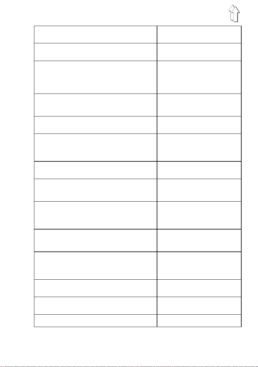
Contents page:
Home
Preface and general safety instructions
Part 1: Operat ing instruc tions Cl. 467
1. Product description
2. Designated use
3. Sub-classes
3.1 Op tional Equipment . . . . . . . . . . . . . . . . . . . . . . . . . . . . 6
4. Technical data
5. Operation
5.1 Threading the needle threa d . . . . . . . . . . . . . . . . . . . . . . . . 9
5.2 Adjustin g needle-thre ad t ension . . . . . . . . . . . . . . . . . . . . . . 9
5.3 Opening the needle-thread tensioner . . . . . . . . . . . . . . . . . . . 9
5.4 Winding on the lo oper thread . . . . . . . . . . . . . . . . . . . . . . . 11
5.5 Fitting th e looper-thread bobbin . . . . . . . . . . . . . . . . . . . . . . 11
5.6 Adjustin g looper-thre ad t ension . . . . . . . . . . . . . . . . . . . . . . 13
5.7 Fitting and repl acing the needle . . . . . . . . . . . . . . . . . . . . . . 13
5.8 Lifting the sewi ng feet . . . . . . . . . . . . . . . . . . . . . . . . . . . 15
5.9 Arres ting the sewing feet in the up posi tion . . . . . . . . . . . . . . . 15
5.1 0 Adjusting the sewing-foo t stroke . . . . . . . . . . . . . . . . . . . . . 15
5.11 Adjusting the sewing-foot pressure . . . . . . . . . . . . . . . . . . . . 16
5.1 2 Adjusting the stitch leng th . . . . . . . . . . . . . . . . . . . . . . . . . 16
6. Control unit and operating panel
6.1 Gener al . . . . . . . . . . . . . . . . . . . . . . . . . . . . . . . . . . . 17
6.2 Opera ting-pane l keys . . . . . . . . . . . . . . . . . . . . . . . . . . . . 18
6.3 Ch ang ing parameter values . . . . . . . . . . . . . . . . . . . . . . . . 19
. . . . . . . . . . . . . . . . . . . . . . . . . . . . 5
. . . . . . . . . . . . . . . . . . . . . . . . . . . . . . 5
. . . . . . . . . . . . . . . . . . . . . . . . . . . . . . . . 6
. . . . . . . . . . . . . . . . . . . . . . . . . . . . . . . 6
7. Sewing
8. Maintenance
8.1 Clean ing and testin g . . . . . . . . . . . . . . . . . . . . . . . . . . . . 23
8.2 Lubrication . . . . . . . . . . . . . . . . . . . . . . . . . . . . . . . . . 27
. . . . . . . . . . . . . . . . . . . . . . . . . . . . . . . . . . . 21
. . . . . . . . . . . . . . . . . . . . . . . . . . . . . . . . 23

9. Optional Equipment
9.1 Electropneumatic Seam Bartacking and Sewing Foot Lift (RAP 13-4) 28
9.1.1 Function . . . . . . . . . . . . . . . . . . . . . . . . . . . . . . . . . . 28
9.1.2 Keys on the Machine Arm . . . . . . . . . . . . . . . . . . . . . . . . 29
9.1.3. Sewing . . . . . . . . . . . . . . . . . . . . . . . . . . . . . . . . . . . 30
. . . . . . . . . . . . . . . . . . . . . . . . . . . 28

1. Product description
The
DÜRKOPP ADLER 467
of applications.
Flat-bed double lockstitch sewing machine with underfeed, needle feed and
•
alternating-foot overfeed.
Sub-classes av ai l able with or without thread cutter b eneath the needle pl ate.
•
Thread control wi t h one main tensioner.
•
Maximum cleara nce beneath lifted sew i ng feet 16 mm.
•
Stroke of alternating sewing feet with the sewing m achine at a halt ad j u stable
•
between 1.5 and 6 mm by press-button and handwheel (adjusting cam).
Three oil-filling points for manual lubrication of sewing head and shuttle bearing.
•
Large, two-part vertical shutt l e (to the right of the needle) with bo bbin-housing lift .
•
A safety coupling prevents the shuttle from disturbance or damage if thread gets
•
into the shuttle track, blocking the shuttle.
is a special sewing machine with a comprehensive range
2. Designated use
The
materials. As a rule such materials are fabrics consisting of textile fibres, but they also
include leather. They are used in the clothing, domestic-upholstery and
automobile-upholstery industries.
This special sewing machine can also be used to execute so-called technical seams.
However, the operator must carry out an assessment of the p ossible dangers (wit h
which
comparatively unusual and they are potentially of enormous diversity. Depending on the
outcome of this assessment it may be necessary to take special safety precautions.
Generally speaking material processed with this special sewing machine must be dry,
its thickness when compressed by the lowered sewing fe et must not exceed 10 mm and
it must contain no hard objects, since otherwise the operator of the machine would have
to wear protective goggles (which cannot at present be supplied).
The seam is gene rally executed with tex tile-fibre sewing thr eads of dimensions up t o
11/3 NeB (cotton thread), 11/3 Nm (synthetic thread) or 11/4 Nm (covering yarn). The
use of any ot her threads must a lso be subject to an assessment of the risks involved
and the taking of any necessary safety precautions.
The premises in which this special sewing machine is set up and operated must be dry
and well-maintained. If it is to be used in premises which are not dry and
well-maintained, special precautions may be necessary: these must be the subject of
an agreement (see EN 60204-3-1:1990).
As manufactu rers of industrial se wing machines we work on the assumption that
personnel working on our machines will be at least semi-skilled, so that they can be
presumed to be familiar with all normal operations and with the dangers inherent in
them.
is a special sewing machine designed for use with light to medium-heavy
467
DÜRKOPP ADLER AG
would be hap p y to assist), as such applications are
5

3. Sub-classes
467-183080
467-183081
: single-needle flat-bed double-lockstitch sewing machine with
underfeed, needle feed and alter nating-foot overfeed
: as 467-183080,
but with electromagnetic thread cutter beneath the needle plate
3.1 Optional equipment
Order no. Optional equipment
RAP 13-4 Electropneumatic seam bartacking and sewing foot lift
WE-6 Maintenance unit
797 3031 Pneumatic connection package
For sewing machines with thread trimmer (Subclass
End bartack foot-operated, in t e rmediate bartack hand-operated,
bartack suppression,
stitch-in-stitch sewing, sewing foot lift foot-operated.
For electropne um atic optional equipment RAP 13-4.
For the pneumat i c connection of stands with maintenance un i t
and pneumat i c optional equipment. Consisting of connection
hose (length 5 m, diameter 9 mm), hose nozzles, hose clamps,
coupling socket and coupling plug.
467-183081
4. T echnical data
Noise:
workplace emission value
as specified by DIN 45635-48-A-1-KL2
).
467-183080
467-183081
6
:
:
Lc = 84 dB (A)
stitch length: 7,2 mm
sewing-foo t stroke: 1.5 mm
stitch rate: 2800 per min.
Sewing material: G1 DIN 23328 4-layer
Lc = 85 dB (A)
stitch length: 7.2 mm
sewing-foo t stroke: 5.0 mm
stitch rate: 2000 per min.
Sewing material: 2-ply Skai 1.6 mm 900 g/m
Lc = 84 dB (A)
stitch length: 7,2 mm
sewing-foo t stroke: 1.5 mm
stitch rate: 2800 per min.
Sewing material: G1 DIN 23328 4-layer
Lc = 85 dB (A)
stitch length: 7.2 mm
sewing-foo t stroke: 5.0 mm
stitch rate: 2000 per min.
Sewing material: 2-ply Skai 1.6 mm 900 g/m
2
DIN 53352
2
DIN 53352
needle system: 134-35
needle thickne ss (depending on the E no.):[Nm] 90 - 160
maximum sewing-thread thickness:
- cotton [NeB] 11/3
- synthetic sewing yarn [Nm] 11/3
- covering yarn [Nm] 11/4
maximum bobbin capacity
with synthetic sewing yarn Nm 30/3: ca. [m] 35
maximum stitch rate: 2800 per min.
maximum stitch length:
- forwards: [mm] 9
- backwards: [mm] 9
maximum sewing-foot stroke: [mm] 6
feeder stroke: [mm] 0.5
(above needl e plate)
maximum clearance under sewing feet:
- when sewing [mm] 10
- when raised [mm] 16
Operating pressure: [bar] 6
(when equipp ed with RAP 13-4)
rated voltage: 3 x 400 V, 50 Hz
3 x 230 V, 50 / 60 Hz
1 x 230 V, 50 / 60 Hz
dimensions (H x W x D): [mm] 1570 x 500 x 1050
working height (ex works): [mm] 790
weight (upper part of machine only ): c a.[kg] 56
7
1
2
3
Fig. a: correct threa d l oop in the centre
Fig. b: needle-threa d t ension too strong or
Fig. c: needl e-thread tension too strong
8
of the materi al
too weak
or
looper-threa d tension too weak

5. Operati on
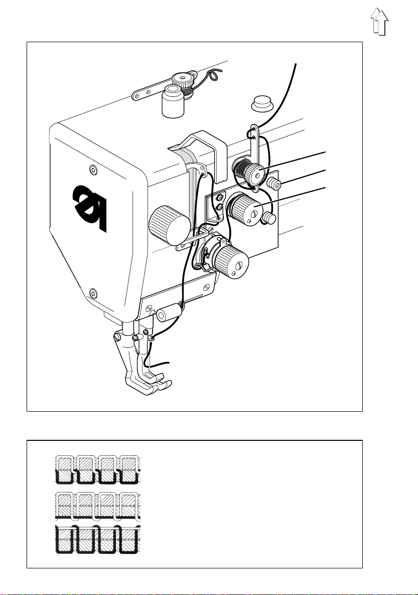
5.1 Threading the needle thread
Caution - danger of injury
Turn off the main switch.
The needle thread may only be threaded with the sewing
machine at a hal t .
–
Thread the needle thread as shown in the illustration.
5.2 Adjusting needle-thread tension
Preliminary tension 1
On the
467-183081
the thread cutter to function reliably when the main tensioner 3 is open.
The preliminar y t ension 1 should be set l ower than the main te nsion 3.
–
Adjust preliminary tension 1 by rota t i ng the Knurled nut.
–
After major changes to prelimin ary tension 1 the ma i n tension 3 should als o be
adjusted accordingly.
Main tension 3
The main tension 3 should be set as low as possible.
The looping of the threads must be in the centre of the material (see fig. a).
With thin material excessive thread t ension can cause unwanted gathering and thread
breakage.
–
Adjust the main tension 3 so that the stitches are uniform.
machine the needle thread needs to be under residual tension for
5.3 Opening the needle-thread t ensioner
Automatic
The main tensioner 3 is opened automatically:
–
when the thread is severed (sub-class
Manual
The main tensioner 3 is opened manually:
–
when button 2 i s pressed.
The main tensi oner 3 remains open for as long as button 2 is hel d down.
–
when the sewing feet are raised with the knee lever (see chapter 5.8).
–
when the sewing feet are arrested in the up position (see chapter 5.9).
467-183081
).
9
1 2
4 5
3
10
4 8
6 7 5
6 7
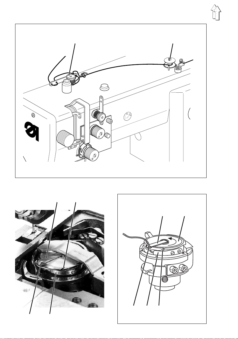
5.4 Winding on the looper thread
Caution - danger of injury
Turn off the main switch.
The looper thread may be threaded for winding on only
when the sewing machine is switched off.
–
When winding on for sewing with no underlay material:
arrest the sewing feet in the up position (see chapter 5.9).
–
Thread looper thread as shown in the upper illustration.
–
Wind about 5 coil s of looper thread anti -clockwise onto the bobbin core.
–
Place bobbin on bobbin winder 2.
–
Swivel bobbin-winder lever 3 against the bobbin.
–
Adjust tension 1.
The looper thr ead should be wound on with minimal tension .
–
Sew.
The bobbin-wi nder lever 3 terminates the process as soon as t he bobbin is full.
5.5 Fitting the looper-thread b obbin
Caution - danger of injury
Turn off the main switch.
The looper-thread bobbin may only be changed with the
sewing machine at a halt.
Removing empty looper-thread bobbin
–
Press leaf spr i ng down and push righ t-hand needle-plate slide aside.
–
Raise bobbin-housing shutter 4 .
–
Remove empty looper-thread bobbin.
Threading looper thread
–
Place full bobbin 8 in bobbin housing:
when the thread is wound off the bobbin must rotate in the direction of the arrow.
–
Draw looper thread through slit 5 down to tensioning spring 7.
–
Draw looper thread into slit 6.
–
Cut looper thread to a length of about 3 cm.
–
Close bobbin-housing shutter 4.
–
Draw looper thread through the guide of bobbin-housing shutter 4.
–
Push needle-plate slide back into place.
11

1
2
3
12
4
5

5.6 Adjusting looper-thread tension
Caution - danger of injury
Turn off the main switch.
The looper-thread tension may only be adjusted with the
sewing machine switched off .
Adjusting tensioning spring 2
–
Release right-hand needle-plate s l i de and push aside.
–
Adjust tensioning spring 2 by rotating regulating screw 1.
To increase looper-thread tension:= rotate screw 1 clockwise
To decrease looper-thread tensi on= rotate screw 1 anti-clo ckwise
–
Push needle-plate slide back into place.
Note:
The conical spri ng in the bobbin housing has the following functions:
–
When the bobbin-housing shutter is open it raises the bobbin slightly for removal.
–
It prevents the bobbin from "running on" when the machine halts or if the looper
thread is wound off spasmodically.
5.7 Fitting and replacing the needle
Caution - danger of injury
Turn off the main switch.
The needle may o nl y be changed with the sewing machine
switched off .
–
Rotate the ha ndwheel until the needle bar 3 has reached its uppermost position.
–
Undo screw 4.
–
Draw the needl e downwards out of the needle bar 3.
–
Insert a new needle as far as it will go into the hole in the needle bar 3.
Important
When viewed from the operating side of the sewing machine the furrow 5 of the
needle must point to the right (see sketch).
–
Tighten screw 4.
IMPORTANT
When fitting a thicker needle the distance of the shuttle
from the needle must be corrected (see Servicing
instructions).
Failure to comply with the above note may lead to the following errors:
when fitting a thinner needle: faulty stit ches, damage to thread
when fitting a t hicker needle: damage to the shutt l e t i p and needle
13

2
1
3
4
5
stitch-length range adjusting cam sewing-foot max. stitch rate
[mm] [item] stroke [mm] per min.
A 1.5 2800
B2600
0 - 6 C 2450
D2300
E2150
F 6,0 2000
14

6 - 9 A - F 1.5 - 6.0 2000
5.8 Lifting the sewing feet
With the machine at a halt the sewing feet are mechanically raised with knee lever 1:
–
Operate knee lever 1.
–
The sewing feet remain lifted for as long as knee leve r 1 is operated.
5.9 Arresting the sewing feet in the up position
The mechanically lifted sewing feet are arrested in the up position with lifting lever 2
(e.g. to wind on the looper thread or replace the sewing f oot).
Lifting lever 2 is located at the rear of the machine arm.
Caution - danger of injury
Turn off the main switch.
Only arrest the sewing feet with the sewing machine
switched off .
–
Swivel lifting lever 2 downwards.
The sewing feet are arrested in the up pos ition.
–
Swivel lifting lever 2 upwards.
The sewing feet are released.
5.10 Adjusting the sewing-foot stroke
The height of the sewing-foot stroke is adjusted with button 3 and handwheel 4.
Caution - danger of injury
Turn off the main switch.
The sewing-foot stroke may only be adjusted with the
sewing machine switched off .
Adjusting the sewing-foot stroke
–
Press button 3 and hold it down.
–
Rotate handwheel 4 until it locks.
–
Continue to rotate the handwheel until the required letter (items A - F) appears in
inspection window 5.
item A: minimum sewi ng-foot stroke (1.5 mm)
item F: maximum sewing-foot stroke (6 mm)
IMPORTANT
Sewing-foot stroke, stitch length and stitch rate are
mutually inte rdependent.
To ensure reliable operation and a long machine life, do not
exceed the maximum stitch rate given in the table.
15

5.11 Adjust ing the sewing-foot pressure
1 2 3
The required sewing-foot pressure is set with knob 1 .
–
To increase sewing-foot pressure = turn knob 1 clockwise
To decrease sewing-foot pressure = turn knob 1 anti-clockwise
5.12 Adjusting the stitch length
–
Set the required stitch length with knob 2.
To increase sti tch length = turn knob 2 cl ockwise
To decrease stitch length= turn knob 2 anti-clockwise
–
To sew bar tacks manually press stitch-regulating lever 3 downwards.
The machine sews backwards for as long as stitch-regulating lever 3 is held down.
The stitch length is the same as that set for forwards sewing.
See also chapter 7.
16

6. Control unit and operating panel
IMPORTANT
This operating m anual covers
change of parameters by the operator.
For a detailed description of the control unit please see the
motor manufacturer’s current operating manual (attached).
6.1 General
The operating panel is used to pro gram the control un i t and to set the seam f unctions.
Depending on the nature of the job, sewing may be executed manually or by seam
programming.
For differing jobs seams can be prog rammed for which th e functions (starting bar tack,
ending bar tack, stitch count, thread cutting etc.) and parameter values (stitch rate,
seam length, rpm etc.) are indiv i dually assigned.
Entry is carried out in programming mode.
The paramete rs and the values assigned are displayed.
The seam progr a m s are not lost even w hen the sewing machine is switched off (battery
buffer).
In order to a void the inadverten t alteration of pre-set functions, operation is divided i nto
various levels (operator, technician, fitter).
The operator (seamstress) can progra m di rectly.
On the other levels access is contingent on the entry of a code number (EFKA).
the key functions and
only
RESET
If the control unit is hopelessly misadjusted, this function allows the technician to reset
all adjusted values to their default (ex-works) settings.
This function is described in the Servicing instructions.
17

6.2 Operating-panel keys
key function settings
start or end programming mode
P
confirm a par a m eter-value change
E
increase a displayed parameter value
+
decrease a d i splayed paramete r value
-
stitch counting ON / OFF
1
programming / executing seams
2
function key (programmable)
3
basic needle position UP / DOWN
4
auto foot lift on stop in mid-seam
5
auto foot lift after thread cut-off
6
starting bar tack
7
ending bar tac k
8
thread cutter THREAD CUTTER /
9
1
1
1
1
ON / OFF
ON / OFF
SINGLE / DOUBLE / OFF
SINGLE / DOUBLE / OFF
THREAD CUTTER
+ TURN BACK / OFF
light-barrie r f unction
0
1
Only by sewing machines with thread trimmer (Subclass 467-183 081) and
2
ON / OFF
electropneumatic seam bartacking and sewing foot lift (RAP 13-4)!
2
Key function is not assigned with this machine class!
18

6.3 Changing parameter values
At the operator level parameter values are change d with the four green keys ("P", "E",
"+", "-") beneath t he display.
The parameter list on the next page lists all the parameters which can be changed from
operator level.
1. Start programming mode
-
Press "P" key.
The LED above th e key flashes.
This indicates t hat the control unit is in programming mode.
2. Display first operator- l evel parameter
-
Press "E" key.
The first par ameter appears in t he display with the c orresponding parameter value.
Example: "
3. Change displayed parameter value
-
Increase or reduce the parameter value with den "+" and "-" keys.
If the "+" or-" key is held down, the parameter value continues to rise or fall until it
is released.
4. Save changed parameter value
-
Press "E" key.
The changed parameter value is saved.
-
The next operator-level parameter appears in the display.
Repeatedly pressing the "E" key successi vely calls up all operator-level parameters.
Arv 250
"
= abbreviated parameter designation
Arv
= parameter value set
250
5. Leaving programming mode
-
Press "P" key.
The last parameter value to have been changed is saved.
-
The control unit leaves programming m ode.
19

"Operator-level" para me ter list:
par ameter function s ettin g
max. min. pre-set value
1
Arv
Arr
Err
Erv
LS
LSF
2
starting bar-tack stitches forwards 254 0 2
1
starting bar-tack stitches backwards 254 0 4
1
ending bar-tack stitches backwards 254 0 2
1
ending bar-tack stitches forwards 254 0 2
light-barrier differential sti tches 254 0 6
2
stitch rate of light-barrier f i l ter 254 0 0
for yard goods
2
LSn
Stc
number of light-barrier seams 15 1 1
stitch rate of seam with stitch- 254 0 10
counting
F
assigns a technician-level 5 1 2
parameter t o key 3
1 = needle cooling ON / OFF
2 = stroke adjustmen t ON / OFF
3 = stroke adjustment
2
2
2
4 = softstart
1
SAv
starting ornamental-stitch bar tack - 254 0 3
stitch count forwards
1
SAr
starting ornamental-stitch bar tack - 254 0 3
stitch count backwards
1
SEr
ending ornamental-stitch bar tack - 254 0 3
stitch count backwards
1
SEv
ending ornamental-stitch bar tack - 254 0 3
stitch count forwards
2
cFw
stitch count r esidual-thread monitor 2540 0 0
stitch counting
2
FES
operating mode of thread-drawin g 6 0 0
mechanism
1
Only by sewing machines with thread trimmer (Subclass 467-183 081) and
electropneumatic seam bartacking and sewing foot lift (RAP 13-4)!
2
Parameter has no function with this machine c l ass!
20

7. Sewing
The descripti on of the sewing proc ess is based on the fo l l owing:
–
The machine in question is a special sewing machine with thread cutter
(sub-class 467-183081).
–
The following function is set on the operating panel:
Basic needle position: DOWN (item 1)
–
Main switch on.
–
The last sewing process was terminated by severing the thread.
Operating and function sequence for sewing:
sewing process operation / explanation
1
Before starting sewing
Initial position
Position the material
at the start of t he seam
At the start of the s eam
Start sewing
Sew starting bar tack
- Pedal in rest position.
Sewing machine at a standstill.
Needle up. Sewing feet down.
-Operate knee lever.
The sewing feet rise.
- Bring material into position.
- Release knee l ever
The sewing feet are lowered onto the material.
- Push pedal forwards and hold it there.
The machine sews at the speed determined by
the pedal.
- Press stitch-regulating lever 1 downwards.
The machine sews backwards for as long as the
stitch-regulating lever is held down.
Speed is determ i ned by the pedal.
21

sewing process operation / explanation
In mid-seam
Interrupt sewing process
Sew the corner
Continue sewing process
(after releasing the pedal)
Sew intermediate bar tack
At the end of the seam
Sew ending bar tack.
Remove material
- Release pedal (rest position).
The machine halts in the 1st posi t i on
(needle down).
The sewing feet are down.
- Release pedal.
The machine halts in the 1st posi t i on
(needle down).
-Operate knee lever.
The sewing feet rise.
- Rotate the material round the needle.
- Release knee lever.
The sewing fee t are lowered onto the m at erial.
- Push the pedal forwards.
The machine sews at the speed determined by
the pedal.
- Press stitch-regulating lever 1 downwards.
The machine sews backwards for as long as the
stitch-regulating lever is held down.
Speed is determined by the pedal.
- Press stitch-regulating lever 1 downwards.
The machine sews backwards for as long as the
stitch-regulating lever is held down.
Speed is determined by the pedal.
- Push the pedal b ackwards.
The thread is sev ered.
The machine ha l ts in the 2nd position .
The sewing feet are down.
-Operate knee lever.
The sewing feet rise.
- Remove sewing material.
1
22

8. Maintenance
Caution - danger of injury
Turn off the main switch.
Maintenance of the sewing machine may only be carri ed
out when it is switched off.
Maintenance work must be carried out no less freque ntly than at the intervals given in
the tables (see "operating hours" column).
Maintenance intervals may need to be shorter when processing heavy-shedding
materials.
8.1 Cleaning and testing
A clean sewing machine is a trouble-free sewing machine.
maintenance work explanation operating
to be carried out hours
Upper part of machine
- Remove lint , pieces of
thread and o t her debris.
Places in specia l need of cleaning:
- area under the needle plate
- feeder
- area around the shuttle
- bobbin housi ng
- thread cutter
- needle-thread tensioner
8
- Clean oil collector.
Sewing drive
- Check the condition and
tension of the V-belt.
- Remove lint and oil spills with a cloth
It must be p ossible to depress the V-belt
by about 10 mm by pressing it with a
finger at its mid-point.
8
160
23

6
4
8
2
10
1
2
3
24

Compressed air maintenance unit (optional equipment)
If the specia l sewing machine is eq ui pped with the compressed air maintena nce unit
WE-6, the maintenance work listed in the table below is also to be conducted.
Required Remarks Operating
maintenance work hours
Compressed air
maintenance unit
- Check the water level in
the pressure regulator.
- Clean the filter insert.
The water level should not climb to the
filter insert 1.
- After screwing in the drain screw 3,
blow the water out of the waterseparator
2 under pressure.
Note:
The water separator 2 is equipped with a
semi-automatic condensation drain.
When falling below a certain pressure,
the condensation is automatically
drained.
Dirt and condensation are removed
through filter insert 1.
- Separate the machine from the
compressed ai r supply.
- Screw in the drain screw 3.
The pneumatic system of the
machine mus t be pressure-free.
- Screw water separator 2 off.
- Screw filter insert 1 off
Wash out the fi l ter case and filte r
insert with naptha (
solvents!
- Reassemble the maintenance unit again
and connect.
) and blow ou t clean.
no
40
500
25

2
1
3
26
4

8.2 Lubrication
Caution - danger of injury
Oil can cause skin eruptions.
Avoid protracted contact with the s ki n.
In the event o f contact, thoroughly wash the affected area .
IMPORTANT
The handling an d disposal of mineral oi l s is subject to legal
regulation.
Deliver used oil to an authorised collection point.
Protect your environment.
Take care not to spill oil.
To lubricate the special sewing machine use only
equivalent oi l of the following specification:
–
viscosity at 40° C : 10 mm2/s
–
flashpoint: 150 °C
ESSO SP-NK 1 0
following part numbers:
2-litre container: 9047 000013
5-litre container: 9047 000014
maintenance work explanation operating
to be carried out hours
- Lubricate the upper part of
the machine.
- Lubricate the shuttle. - Remove knee lever.
- Lubricate the lower part
of the machine.
is available from
DÜRKOPP-ADL ER A G
- Fill tube 1 to the brim with oil.
The oil slowly reaches the upper part
of the machin e through the felt beneath
the tube.
- Turn the upper p a rt of the machine over.
- Fill tube 4 with oil up to the "
mark.
- Unscrew oil-filler cap 2.
- Top up with oil.
- Check oil le vel at sight glass 3.
The oil level must be between the
upper red line and the "
- Replace oil-filler cap.
- Remove any oil which has overflowed
into the oil collector.
ESSO SP-NK 1 0
retail outlets under the
lubricating oil or an
"
max.
" [] line.
LEER
8
8
40
27

9. Optional Equipment
9.1 Electropneumatic Seam Bartacking and Sewing Foot Lift (RAP 13 -4 )
The electropneumatic seam bartacking and sewing foot lift (
for special sewing machines with thread trimmer (Subclass
It makes possible the following supplementary functions:
–
Beginning and end bartack sewin g , foot-operated (vi a pedal)
–
Bartack suppression
–
Stitch-in-stitch sewing (fancy bartacking)
–
Intermediate bartack sewing, hand-operated (via key on the machine arm)
–
Sewing foot lift, foot-operated (via pedal)
RAP 13-4
467-183 081
9.1.1 Function
4
1
2
2
3
) is only available
).
Seam bartacking
–
At the beginning of the bartack the piston rod of cylinder 1 runs out and moves the
stitch regulator into the position for sewing in reverse.
–
The machine sews in reverse as long as the piston rod is run out.
The stitch length corresponds to the stitch length set for sewing forward.
During the seam bartacking, the bartacking rpm (fa ctory setting 1200 m i n
effect.
Sewing foot lift
–
Step the pedal half back.
The piston rod of cylinder 3 runs out and operates the lever 4 via the slide 2.
–
The sewing feet lift.
28
-1
) is in

9.1.2 Keys on the Machine Arm
1 2 3 4
Key Function / Operation
1 Activating the intermediate bartack during sewing
- Press key 1 and hold down.
The intermediate bartack is sewn.
The machine sews in reverse as long as key 1 is held down.
without function!
2
3 Suppressing the beginning or end ba rta ck
- Press key 3.
The next beginning or end bartack is
4 Positioning the needle in the high or low position
- Press key 4.
The needle positions in the high or low position.
not
sewn.
29

9.1.3 Sewing
In the description of the sewing, the following preconditions are assumed:
–
Special sewing machine with thread trimmer (Subclass 467-183081) and
electropneumatic seam bartacking and sewing foot lift (RAP 13-4).
–
The following f unctions are set on the control panel:
Beginning and end bartack: ON
Sewing foot position before and after trimming: DOWN
Needle positi on before trimming: DOWN (position 1)
–
The last sewi ng sequence was comp l eted with end bartack and thread trimmi ng.
Operation and function sequence during sewing:
1 2 3
Sewing sequence Operation / Remarks
Before the start of sewing
Initial position
Position the material at
the seam beginning
- Pedal in the rest position. Sewing machine is
stopped.
Needle up. Sewing feet down.
- Press key 3.
The needle positions in the low position.
- Step the peda l half back.
The sewing feet lift.
- Push the materi al t oward the needle.
- Release the pedal.
The sewing feet lower onto the material.
At the seam beginning
Beginning bartack and
continue sewing
Only sew beginni ng bartack
sewing the be gi nning bar-
Not
tack
30
- Step the pedal forward and hold down.
The beginning bartack is sewn.
Then the machine continues sewing with the rpm
determined via the pedal.
- Step the pedal briefly forward.
The machine stops in the 1st position (needle
down) after t he sewing of the begi nning bartack.
- Press key 2 (b artack suppression).
- Step the pedal forward. The machine sews with
the rpm determined via the pedal.

Sewing sequence Operation / Remarks
At the seam middle
Interrupting the sewing sequence
Sewing the corner
Continuing t he sewing sequence (after release of the pedal)
- Release the pe dal (rest position) .
The machine st ops in the 1st position
(needle down ).
The sewing feet are down.
- Step the pedal half back.
The machine st ops in the 1st position
(needle down ).
The sewing feet are raised.
- Turn the material aro und the needle.
- Step the pedal forward.
The machine sews with the rpm determined via
the pedal.
The beginning b artack is
not
sewn.
Sewing the intermediate bartack
At the seam end
Removing the material
lifting the sewing feet.
Not
sewing the end bartack
Not
- Press key 1 and hold the pedal .
The machine sew s i n reverse as long as key X
is pressed.
The rpm is determined via the pedal.
- Step the pedal completely back and hold down.
The end bartac k i s sewn.
The thread is trimmed.
The machine stops in the 2nd position .
The sewing feet are lifted.
- Briefly step the pedal completely back.
The end bartac k i s sewn.
The thread is trimmed.
The machine stops in the 2nd position .
The sewing feet are down.
- Press key 2 (bartack suppression).
Step the pedal completely back.
The end bartack i s
The thread is trimmed.
The machine stops in the 2nd position .
The position of the sewing feet i s dependent on
the position
of the pedal:
a) Pedal stepped back and held down:
- Sewing feet lifted.
b) Pedal released (rest position):
- Sewing feet down.
not
sewn.
31
 Loading...