

Page 1

Contents Page:
Home
Part 2: Installation Instructions Cl. 467
1. Scope of Delivery
2. General Information and Transport Safeguards
3. Assembling the Stand
3.1 Assembling the Stand P arts . . . . . . . . . . . . . . . . . . . . . . . . 5
3.2 Completing the Table Top and Mounting on the Stand . . . . . . . . . . 5
3.3 Setting the Work H eight . . . . . . . . . . . . . . . . . . . . . . . . . . 5
4. Mounting and Connecting the Sewing Drive
4.1 Ge neral Information . . . . . . . . . . . . . . . . . . . . . . . . . . . . 7
4.2 M oun ting the Sewing Drive un der the Table Top . . . . . . . . . . . . . 7
4.3 Connecting the Sewi ng Drive . . . . . . . . . . . . . . . . . . . . . . . 9
4.4 Checking the Nomina l Voltage . . . . . . . . . . . . . . . . . . . . . . . 9
5. Mounting the Machine Head
5.1 Inse rting the Machi ne Head . . . . . . . . . . . . . . . . . . . . . . . . 11
5.2 Placing and Tensioni ng the V-belt . . . . . . . . . . . . . . . . . . . . . 11
5.3 Attaching the Pedal . . . . . . . . . . . . . . . . . . . . . . . . . . . . . 13
5.4 Pote ntial Compensation . . . . . . . . . . . . . . . . . . . . . . . . . . 15
5.5 F astening the Knee L ever . . . . . . . . . . . . . . . . . . . . . . . . . 15
5.6 Attaching the Control Panel . . . . . . . . . . . . . . . . . . . . . . . . 15
6. Attaching, Connecting and Setting the Synchronizor
6.1 Attaching the Synchronizor . . . . . . . . . . . . . . . . . . . . . . . . 16
6.2 Connecting the Synchronizor . . . . . . . . . . . . . . . . . . . . . . . 16
6.3 Ch ecking the Direction o f Tu rn . . . . . . . . . . . . . . . . . . . . . . 17
6.4 Ch ecking the Position in g . . . . . . . . . . . . . . . . . . . . . . . . . . 18
6.5 Settin g the Positions . . . . . . . . . . . . . . . . . . . . . . . . . . . . 18
. . . . . . . . . . . . . . . . . . . . . . . . . . . . . 3
. . . . . . . . . . . 3
. . . . . . . . . . . . . 7
. . . . . . . . . . . . . . . . . . . . . . . 11
. . . . . . . . 16
7. Pneumatic Connection
7. Lubrication
7.1 Filling the Oil Reservoirs . . . . . . . . . . . . . . . . . . . . . . . . . . 24
7.2 Oiling the Wicks and Felt Pads . . . . . . . . . . . . . . . . . . . . . . 26
8. Sewing Trial
. . . . . . . . . . . . . . . . . . . . . . . . . . . . . . . . . 24
. . . . . . . . . . . . . . . . . . . . . . . . . . . . . . . . 27
. . . . . . . . . . . . . . . . . . . . . . . . . . 23
Page 2
5
6
7
1
2
3
4
12
8
9
10
11
Page 3

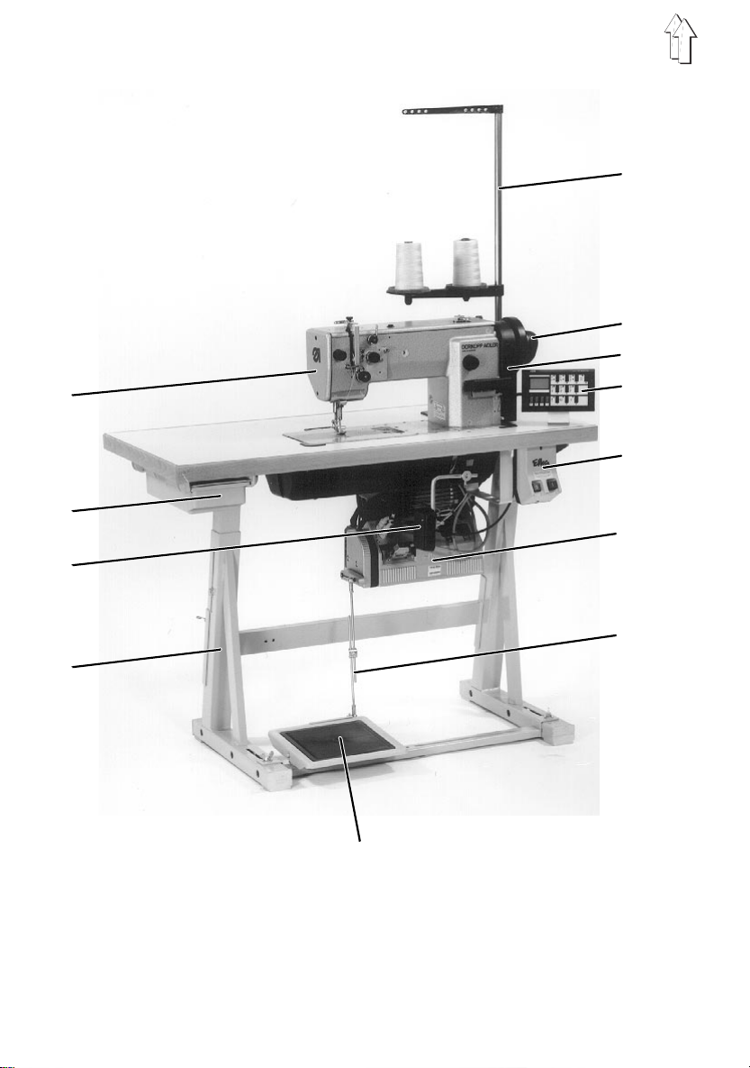
1. Scope of Delivery
The scope of del i very
Please check if all required parts are present before installation.
This descripti on applies fo r a sewing mach i ne whose individual components are all
supplied by
Standard equipment
–
–
–
–
–
–
–
–
–
–
–
–
–
–
DÜRKOPP-ADLER
Machine head
1
Drawer
2
Knee lever
3
Stand
4
Yarn stand
5
Synchronizor (dependent on drive package)
6
Belt guard
7
Control pane l (dependent on drive package)
8
Main switch
9
Sewing drive
10
Pedal rod
11
Pedal
12
Belt pulley and V-belt
Small parts in the accessories pack
is dependent on your order
.
(with or without thread trimmer depending on subclass):
.
2. General information and Transport Safeguards
ATTENTION !
The special sewing machine may only be installed by
trained, skilled personnel.
Different drive packages are available for the
Chapter 4.1 ).
All illustrations shown in these installation instructions refer
to a special sewing machine with following sewing drive:
Efka DC1600/DA820V.
Please note t hat your speci al sewing machine may deviate
from the illustrations because of the differing equipment
variants!
Transport safeguards
If you have bought a fitted special sewing machine, the following
transport safeguards are to be removed:
–
Securing bands and wooden slats on machine head, table and stand
–
Securing bloc k and bands on t he sewing drive
(see also
467
3
Page 4
11
1
2
4
3
4
8
9
5
10
12
6
13
7
14
15
4
Page 5

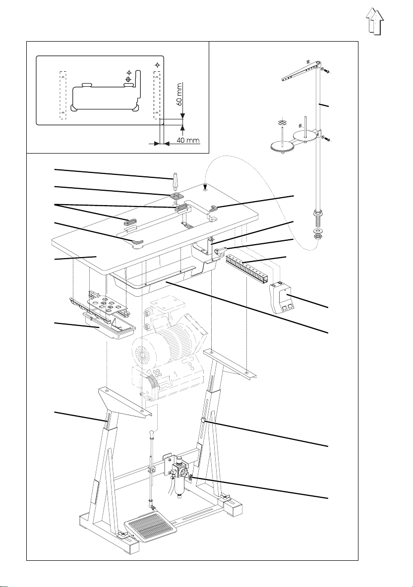
3. Assembling the Stand
3.1 Assembling the Stand Parts
–
Assemble the individual parts of the stand as shown in the illustration.
–
Turn the adjusting screw 15 for a sec ure positioning of the stand.
The stand must rest with all four feet on the floor!
3.2 Completing the Table Top and Mounting on the Stand
–
Hammer the
–
Insert the
–
Press the
top.
–
Screw on th e
–
Screw on th e
–
Screw on th e
–
Screw on th e
cable duct 10 under the table top.
–
Lay
mains cable
–
Lay the
duct 10.
–
Screw
for mounting the optional equipment RAP 13-4.
The bar 8 is mounted with the aid of the three threaded inserts in the table top.
–
Fasten the
–
Fasten the
The alignment on the stand can be seen in the dimensions in the sketch.
–
Insert the
and washers.
Mount and align the thread spool hold er and take-o ff arm.
The thread spool holder an d take-off arm m ust lie verti cally above eac h other.
machine head support 1
into the drilled hole for the cable passage through the table top.
plug 2
rubber rests 3 and 4
drawer 6
main switch 12
cable duct 10
mounting 9 for the tension relief
connection cable of the sewing drive
on under the table top. The bar serves to reinforce the table top and
bar 8
oil collector 13
table top 5
yarn stand 11
with its mountings at the left under the table top.
at the right under the table top.
behind the main switch 12 under the table top.
from main switch 12 through c able duct 10 and m ounting 9.
under the ta bl e cutout with wood screws.
on the stand with wood screws (B8 x 35).
into the drilled hole of the table top and fasten with nuts
into the drilled hole in the table top.
for the machine head into the recesses of the table
of the conn ection leads behind
from main switch 12 through c able
3.3 Setting the Work Height
The work height is adjustable between 750 and 900 mm (measured to the upper edge
of the table t op).
–
Loosen the screws 14 on both legs of the stand.
–
Set the table top horizontally to the desired work height.
In order to avoid tilting , pull out or push in the table top uniformly on both sides.
The scales 7 on the outer sides of the legs serve as setting aids.
–
Tighten both screws 14.
5
Page 6
1
2
3
4
5
6
Page 7

4. Mounting and Connecting the Sewing Drive
4.1 General Information
Drive packages
Complete drive packages are available for the
The sewing drives available for each subclass are to be found in the following table.
Subclass Sewing drive Control panel
467
.
467-183080
467-183081
The drive packages contain the following parts:
–
Sewing drive
–
Main switch with connect ion leads
–
Control panel
–
Pedal rod
–
Belt pulley
–
V-belt
–
Connection plan
–
Fastening and connection material.
Electro-connection packages
The electro-connection packages contai n all parts required to elect rically conne ct the
machine head wi th the sewing dr i ve:
–
Connection leads
–
Grounding kit
–
Wiring diagram.
FIR 1147-F.7 52.3 -
Efka VD552/4P72 0V V720
Efka DC1600/DA820V V720
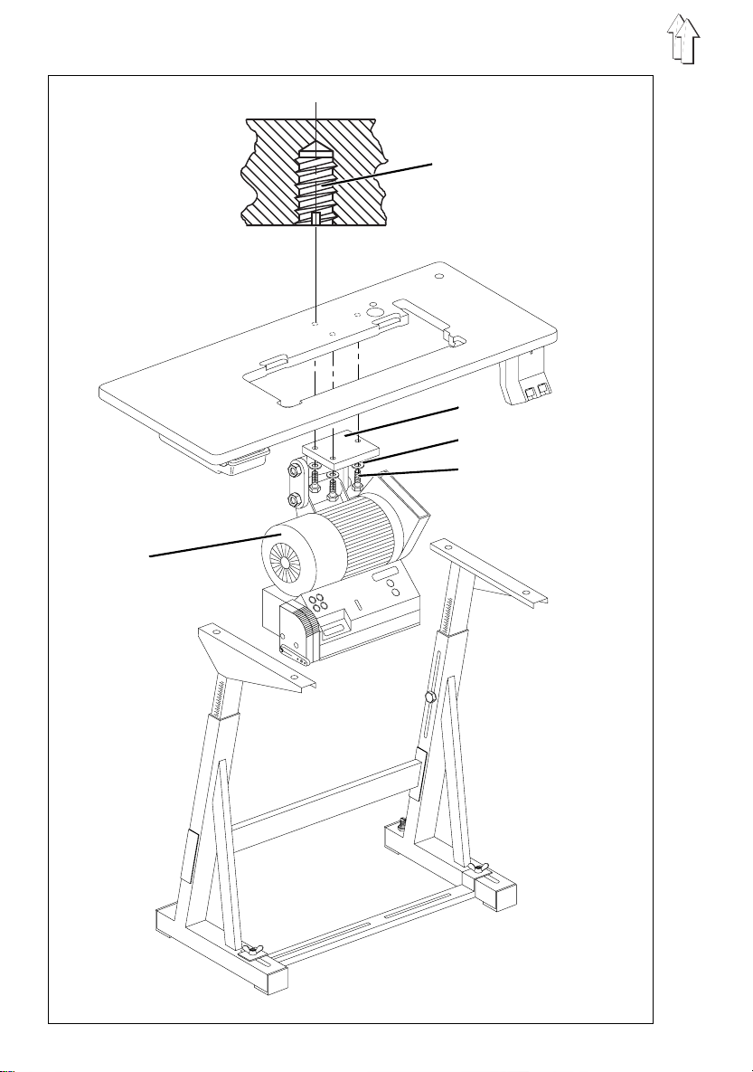
4.2 Mounting the Sewing Drive under the Table Top
–
Fasten the sewing drive 5 (in the illustration type Efka) with its base 2 on the
underside of the table.
For this, screw the three hex-head screws 4 (M8x35) with washers 3 in t o the
threaded inserts 1 in th e t able.
7
Page 8
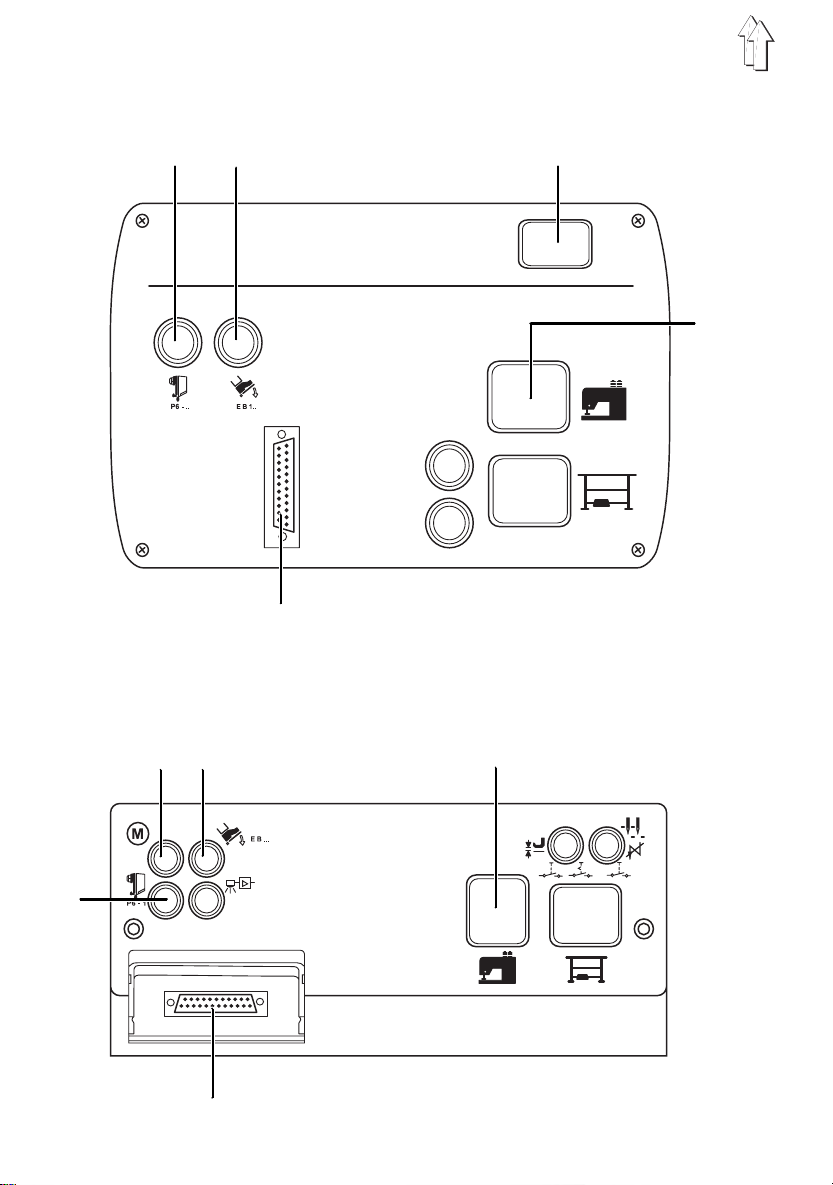
Connection jacks EFKA VD552/4P720V:
1 2 3
5
4
Connection jacks EFKA DC1600/DA820V:
1 2 3
4
5
8
Page 9
4.3 Connecting the Sewing Drive
ATTENTION !
All work on the electrical equipment of the special sewing
machine may o nl y be conducted by electricians or
appropriately trained perso ns.
The mains plug m ust be pulled!
It is essential to follow the operating instructions of
the manufacturer enclosed with the sewing drive !
With all sewing drives (FIR and EFKA):
–
Connect the electrical connection lead from t he main switch on the sewing dr i ve.
Sewing drive EFKA VD552/4P720V:
–
Connect the set value init i ator (pedal) and coupling/brake (see I l l us. pg.12)
Sewing drive EFKA DC1600/DA820V:
–
Connect the commutation initiator and set value initiator (pedal) (see Illus. pg.12).
Connection jack EFKA VD552/4P720V EFKA DC1600/DA820V:
1
2
3
4
5
Not identified connection jacks are
Synchronizor Commutation initiator for DC motor
Set value initiator (pedal) Set value initiator (pedal)
Coupling / brake Sewing machine head
Sewing machine head Synchronizor
Control panel Control panel
not active
with this machine class!
4.4 Checking the Nominal Voltage
ATTENTION !
The nominal vo l tage given on t he identification plate and
the mains voltage must be in agreement.
An adaption t o the local mai ns voltage occurs via the connection terminals on the
transformer of the sewing dri ve .
–
Check the arrangement of th e connections on t he transformer of the sewing drive.
–
If necessary, alter th e connections according to t he existing mains voltage (see
Wiring Diagr am ).
The direct current sewing drive used is operated with a "single-phase alternating
current". I n order that t h ere be no overl o ading of indi vidual phases with the conn ection
of multiple sewing machin es on a 3-phase supply, the following is to be observ ed:
The connections of the individual sewing machines must be spread equally over the
phases of the 3 -phase supply (Wi ri ng see Wiring Diagram).
9
Page 10

1 2 3
4
10
5 6 7
4
6 8 9
10 11
Page 11

5. Mounting the Machine Head
5.1 Inserting the Machine Head
–
Fasten the hinges 1 on the base plate 3 with countersunk screws M6X8.
–
Insert the machine head 2 into the cutout of the table top.
5.2 Placing and Tensioning the V -belt
Remove the protection devices
–
Remove the two-piece belt gu ard 4 and 6 on the machine head.
The mounting screws are accessable through the drilled holes in both parts of the
belt guard.
–
Remove the cover of the belt g uard 8 on the sew i ng drive.
Place the V-belt and attach the belt guard on the machine head
–
Mount the belt pulley 10 (in the accessories pack) on the shaft of the sewing drive.
–
Place the V-belt 5 on the belt pulley on the machine head.
–
Guide the V-belt 5 down through the cutout in the tab l e t op.
–
Tilt the machine head to the back.
–
Place the V-belt 5 on belt pulley 10 on the sewing drive.
–
Return the machine head.
–
Mount the two-piece belt guard 4 and 6 on the machine head.
–
Mount the twi st protection 7 f or the synchronizor on the right-hand part 6 of the belt
guard.
Tensioning the V-belt
–
Loosen screw 9 on the base of the sewing dr i ve.
–
Tension V-belt 5 by slewing the sewing drive 11.
With correct belt tension th e V-belt 5 c an be pressed in approx. 10 mm in t he
middle by fi nger pressure (without much force).
–
Tighten screw 9.
(if attached at delivery)
Mounting the belt guard on the sewing drive
–
Set the belt run-off protection (adjustable cams or a ngles dependi ng on the type of
drive) of the belt guard 8 as follows:
With the machine head tilted back the V-belt 5 must remain on the belt pulleys.
See also the enclosed operating instructions of the motor manufacturer!
–
Screw on the cover of the belt guard 8.
11
Page 12

1
2
3
1 - Set value initiator
4 - Sewing drive
5 - Control box
6 - Connecting cable for commutation output
4
5
6
7 8
12
Page 13

5.3 Attaching the Pedal
–
Mount pedal 7 on stand brace 8.
–
Align pedal 7 sideways as follows:
The hung-in pedal rod 2 must be vertical.
The frame brac e 8 is equipped with slots for the alignment of the pedal.
–
Hang in pedal rod 2.
–
Loosen screw 3 slightly.
–
Set the height of the pedal rod 2 as follows:
The released pedal 7 must have an incline of approx. 10°.
–
Tighten screw 3.
7
13
Page 14

1
2
4
3
5
14
6
5
Page 15

5.4 Potential Compensation
The ground lead 4 (part of the connection package) conducts static charges of the
machine head 2 to ground via the sewing drive 3.
–
Fasten the cable bracket of the ground lead 4 on the base of the se wing drive 3
with screw (M4) and washer.
–
Guide the ground lead 4 up through the drilled hole in the table top.
–
Fasten the ground lead 4 on the hinge 1 of the machine base plate with plug cap,
flat plug and toothed washer.
5.5 Attaching the Knee Lever
The knee lever 6 m echanically r aises the pressure feet.
–
Insert knee lever 6 into the hollow shaft 5 and let catch.
ATTENTION !
Before tilting the machine head back re move the knee
lever 6.
5.6 Attaching the Control Panel
–
Fasten the external control p anel 7 on the table top with mo unting angle 9 and
wood screw.
–
Guide connection lead 8 of the control panel down through the drilled hole in the
table top.
–
Insert the pl ug of the connection lead 8 into the appropriate jack of the drive
controls (see Table pg. 9).
7
8
9
15
Page 16

6. Mounting, Connecting and Setting the Synchronizor
2
3
1
4
5 6
6.1 Mounting the Synchro nizor
–
Place the synchronizor 3 on the handwheel flange.
The groove in the neck 6 of the s yn chronizor housi ng must catch over the twist
protection 5 on the belt guard.
–
Tighten both set screws 2 on the synchronizor collar 1.
6.2 Connecting the Synchronizor
–
Guide the connection lead 4 down through the drilled hole in the table top.
–
Insert the plug of the connection lead 4 into the appropriate jack of the drive
controls (see Table pg. 9).
16
Page 17

6.3 Checking the Direction of T urn
ATTENTION !
Before commissioning the special sewing machine it is
essential to check the directi on of turn of the sewing drive.
Turning on the special sewing machine with an incorrect
direction of turn can lead to damage.
The arrow in the illustration shows the correct direction of turn (
3-phase drives
The direction of turn is determined by the rotary field of the current supply.
–
Insert the mains plug.
–
Check the direction of turn of the motor ventilator wheel by briefly turning on the
main switch.
–
With an incorrect direction of turn chec k i f the current supply generates a clockwise
rotary field.
Is this the case, then two phases in the mains plug must be interchanged.
Direct current drives
The direction of turn is set to
If the special sewing machine was delivered in individual components, then the
direction of turn is to be checked.
The direction of turn is set at the control panel.
With
counterclockwise run
(see instruct i ons of the motor manufacturer).
counterclockwise run
the parameter
ATTENTION !
After a change in the direction of turn the positions must be
programmed ag ai n.
F-161
at the facto ry.
must be set to the value "0"
counterclockwise run
).
17
Page 18

6.4 Checking the Positioning
Reference position
The reference position is the starting point for all positions set at the factory. In the
reference position the lowering needle poi nt lies at the height of the top of the needl e
plate.
Position 1
By sewing machines with thread trimmer the trimming sequence is initiated in the 1st
position. The trimming must occur before the needle low position because the
thread-pull knife would otherwise collide with the bobbin case opener finger.
1
In the 1st position the lower edge of the needle eye of the lowering needle must lie at
one level with the hook covering ring 1.
Position 2
In the 2nd position the thread lever lies in the high position.
18
Page 19

Checking the positioning
–
Turn the main switch on.
–
Briefly step forward on the pedal.
The sewing machi ne positions in position 1.
Check the position of the needle.
–
Step the pedal completely back and hold.
The thread is tr i m m ed.
The sewing machine positions in position 2 (thread lever high position).
–
Check if the thread lever l i es at its upper dead center.
For this, turn the handwhee l back and forth sl i ghtly.
–
This normally completes the check.
Should a correction of the factory sett i ngs be necess ary, proceed as follows fo r the
programming of the positions.
6.5 Setting the Positions
The synchronizor must be reset after the following work:
–
Mounting of the synchronizor during installation of the special sewing machine
–
Screwing off of the synchronizor
–
Replacement of the synchronizor
–
Replacement of the microprocessor of the dirve controls
–
Replacement of the whole driv e c ontrols
No mechanical settings are necessary on the digital synchronizor.
Before commissioning only the reference position must be set.
The machine positions are registered by t he synchronizo r i n steps (incr em ents) and
shown in the di splay.
One rotation of the handwheel correspo nds to 512 steps.
The change in the display occurs in steps o f 2. A change from one to the next display
value thus corresponds to a rotation angle of approx. 1.4°.
The angle sett i ng of positions 1 and 2 to the reference posit i on is each defined by a
specific number of increments.
19
Page 20

Programming steps:
1. Accessing the correction mode
-
Turn the main switch off.
-
Press the "P" key and hold down.
-
Turn the main switch on.
The display shows "
-
Release the "P" key.
2. Changing to the technician level
-
Enter code number "
-
Press the "E" key.
The controls change to the "technician level".
The display shows the parameter no. "
-
When an incor rect code numb er is entered the text "
Repeat the ent ry.
3. Programming the reference position
-
Enter parameter number "
-
Press the "E" key.
The display shows the parameter "
vice routine 1).
The LED above the "F" key blink s.
-
Press the "F" key.
The display shows "
-
Turn the handwh eel at least on e revolution i n t he directio n of run until t he reference positio n i s reached (needle point at needle plate l evel).
-
Press the "P" key.
The set reference position is stored.
".
C-0000
" via the numeric keys "1...0".
1907
F-100
" via the numeric keys "1...0".
170
" with the sho rt designation "
F-170
Position 0
".
".
C-0000 Info F1
" appears.
" (Ser-
Sr1
4. Programming position 1
-
Enter parameter number "
-
Press the "E" key.
The display shows the parameter "
vice routine 2).
The LED above the "F" key blink s.
-
Press the "F" key.
The display shows "
-
Turn the handwh eel until the 1st position is reached.
5. Programming position 2
-
Press the "E" key.
The display shows "
-
Turn the handwheel until the 2n d position is rea ch ed.
Position 1
Position 2
" via the numeric keys "1...0".
171
F-171
" and the corre sponding number of increments.
" and the corre sponding number of increments.
20
" with the sho rt designation "
Sr2
" (Ser-
Page 21

6. Exiting the correction mode
-
Press the "P" key 2x.
7. Saving the setting
-
Briefly step forward on the pedal.
-
Step the pedal completely back.
Thread trimming occurs. The pressure feet rise.
The corrected setting is stored.
-
The sewing machi ne is ready for operation.
ATTENTION !
To complete the correction procedure it is essential to se w
a little. Only then is the changed setting finally stored.
If no sewing occurs the setting is lost when the main switch
is next turned off.
21
Page 22

1
2
3
4
5
6
6
4
8
2
10
7
22
5
Page 23

7. Pneumatic Connection
For the operation of the elect ropneumatic seam bartacking and sewing foot l i ft available
as optional equipment (
water-free compressed air.
–
Connect the electropneumat i c seam bartacking and sewing foot lift to the in-house
compressed air supply with connection hose 5 (Ø = 9 mm).
–
Pneumatic connection package
A pneumatic connection package for stands with compressed air maintenance unit
and pneumatic optional equ i pm ent is available under Order n o. 797 3031.
It contains following parts : - Connection hose, 5m long, Ø = 9 m m
RAP 13-4
7.1 Compressed Air Maintenance Unit
The compressed a i r maintenance u ni t WE-6 for pneum atic optional e quipment is
available under Order no. 9781 000002.
), the special sewing machine must be supplied with
ATTENTION !
The flawless functioning of th e electropneum atic seam
bartacking and sewing foot li f t (
when the line pressure is 8 to 10 bar.
The operating pressure of the special sewing machine is
.
bar
- Hose nozzle s and hose clamps
- Coupling socket and coupling plug
RAP 13-4
) is only assured
6
Connecting the compressed air maintenance unit
–
Fasten the compressed air maintenance u ni t 3 on the sta n d brace 4 with angle 2
and bracket 1.
–
Connect the compressed ai r m aintenance u nit 3 to the in-house compressed air
supply with connection ho se 5 (Ø = 9 mm) and hose coupling R1/4".
Setting the operating pressure
The operating pressure is
It can be seen at the manometer 7.
–
For setting the operating pressure pull up knob 6 and turn.
Increase pressure = Turn knob 6 clockwise
Decrease pressure = Turn knob 6 counterclockwise
6 bar
.
23
Page 24

7. Lubrication
Caution Risk of Injury !
Oil can cause s kin rashes.
Avoid longer ski n contact.
After contact wash yourself thoroughly.
ATTENTION !
The handling and disposal of mineral oils is subject to legal
constraints.
Deliver used oil to an authorized reception point.
Protect your environment.
Take care not to spill any oil.
For filling the oil reservoir use only
with following specification:
–
Visc osity at 40° C : 10 mm2/s
–
Fla sh point : 150 °C
ESSO SP-NK 10
following pa rt s no.s:
2 liter container: 9047 000013
5 liter container: 9047 000014
is available from
ESSO SP-NK 1 0
DÜRKOPP-ADLER AG
lubricating oi l or an equivalent oil
sales offices under the
7.1 Filling the Oil Reservoirs
Lubrication of the machine bottom
–
Screw out the oil fill screw 2.
–
Fill oil.
–
Check the oil l evel at the viewing glass 3.
The oil level must lie between the two red marking lines.
–
Screw the oil fill screw 2 in again.
–
Remove overflow oil from t he oil collector.
Lubrication of the machine head
–
Fill tube 1 up to the edge with oil.
The oil slowly rea ches into the machine head through the felt under the tube .
24
Page 25

Hook lubrication
–
Remove the knee lever.
–
Tilt the machine head back.
–
Fill the tube 4 up to the "
" mark with oil.
max.
ATTENTION !
In order to assure a sufficient lubrication of the hook during
the run-in period a relatively large quantity of oil was set at
the factory.
The setting is to be checked and reduced to the required
quantity after the run-i n period (see Se rvice Instruct i ons).
1
2
3
4
25
Page 26

7.2 Oiling the Wicks and Felt Pads
During inst al l ation and af t er longer idle periods the wicks and the f elt 1 in the ma schine
head are to be soaked with a little oil.
1
2 3
–
Screw off the head cover 2.
–
Soak the wicks and felt 1 with a little oil.
–
Replace the head cover 2 and screw fast.
Thereby clamp the felt tongue 3 of the head cover between the draw-off felt 6 and
the nippel of t he wick 5.
The foil 4 must touch on the inside of the head cover 2.
26
4
5
6
Page 27

8. Sewing Trial
A sewing trial is to be conducted after completion of the installation work!
–
Plug in the mains plug.
Caution Risk of Injury !
Turn the main switch off.
Thread the und erthread for wi nding only with the sewing
machine turn ed off.
–
Thread the underthread for winding (see Operating Instructions).
–
Arrest the pressure feet in the high position (see Operating Instructions).
–
Turn the main switch on.
–
Fill the bobbin at a low sewing speed.
Caution Risk of Injury !
Turn the main switch off.
Thread the nee dl e and underthr eads only with the sewing
machine turn ed off.
–
Thread needle and underthreads (see Operating Instructions).
–
Select the material to be sewn.
–
Conduct the sewing trial first with low and then with continuously increasing speed.
–
Check if the s eams meet the desired requirements.
If the requirements are not met, change the thread tensions
(see Operatin g I nstructions) .
the setting s given in the Se rvice Instruc tions are also t o be checked a s required
and, if ne cessary, corrected.
27
 Loading...