


Contents Page:
Home
Part 2: Installation Instructions cl. 381 - 382
1. Delivery scope
2. General and Transportation safety precautions
3. Stand installation
3.1 Installing stand parts . . . . . . . . . . . . . . . . . . . . . . . . . . . . 5
3.2 Completing table top and fastening to the stand . . . . . . . . . . . . . 5
3.3 Setting workin g height . . . . . . . . . . . . . . . . . . . . . . . . . . . 7
4. Installing and connecting sewing motor
4.1 General . . . . . . . . . . . . . . . . . . . . . . . . . . . . . . . . . . . 7
4.2 Fitting sewing motor under the table t op . . . . . . . . . . . . . . . . . 7
5. Installing machine head
5.1 Inserting machine head . . . . . . . . . . . . . . . . . . . . . . . . . . 9
5.2 Fitting the keys . . . . . . . . . . . . . . . . . . . . . . . . . . . . . . . 9
5.3 Placing and tensioning the V-belt . . . . . . . . . . . . . . . . . . . . . 9
5.4 Fitting the pedal . . . . . . . . . . . . . . . . . . . . . . . . . . . . . . . 11
5.5 Fastening the knee lever . . . . . . . . . . . . . . . . . . . . . . . . . . 11
5.6 Fittin g the control panel . . . . . . . . . . . . . . . . . . . . . . . . . . 13
5.7 Fitting the sewing lamp . . . . . . . . . . . . . . . . . . . . . . . . . . . 13
6. Electrical connection
6.1 General . . . . . . . . . . . . . . . . . . . . . . . . . . . . . . . . . . . 14
6.2 Checkin g no minal voltage . . . . . . . . . . . . . . . . . . . . . . . . . 14
6.3 Connecting sew ing motor . . . . . . . . . . . . . . . . . . . . . . . . . 14
6.4 Connection bushes on control b ox . . . . . . . . . . . . . . . . . . . . 15
6.5 Establishing cable co nnections . . . . . . . . . . . . . . . . . . . . . . 16
6.6 Installing the positioner . . . . . . . . . . . . . . . . . . . . . . . . . . 16
6.7 Equipotential bonding . . . . . . . . . . . . . . . . . . . . . . . . . . . 17
6.8 Checkin g the direction of rotation . . . . . . . . . . . . . . . . . . . . . 18
6.9 Ch ecking the positioning . . . . . . . . . . . . . . . . . . . . . . . . . . 19
6.10 Settin g the positions . . . . . . . . . . . . . . . . . . . . . . . . . . . . 19
. . . . . . . . . . . . . . . . . . . . . . . . . . . . . . . 3
. . . . . . . . . . . 3
7. Pneumatic connection
8. Oil lubrication
9. Sewing test
. . . . . . . . . . . . . . . . . . . . . . . . . . . . . . . 25
. . . . . . . . . . . . . . . . . . . . . . . . . . . . . . . . . 26
. . . . . . . . . . . . . . . . . . . . . . . . . . 23
6
7
1
8
variocontrol 720
0
98
7
6
45
32
1
+
E
P
9
2
I
0
10
3
11
12
4
13
5
14
15
2

1. Delivery scope
The scope of del i very
Before installing, please check whether all the required parts are available.
Equipment
–
–
–
–
–
–
–
–
–
–
–
–
–
–
–
–
–
(depending o n t he sub-class) :
1
2
3
4
5
6
7
8
9
10
11
12
13
14
15
Sewing lamp
Machine head
Table top
Drawer
Stand
Thread unwinder
Positioner
Belt guard
Control pane l
Main switch
Knee lever
Sewing motor
Conditioning unit
Pedal linkage
Pedal
Belt pulley and V-belt
Small parts in the accessories
depends on your order.
2. General and Tr ansportation safety precautions
NOTE !
The special sewi ng machine should be operated
exclusively by qualified operators.
If you have received a special sewing machine that has been prepared for a safe
transportation, remove following safety elements:
–
Safety bands and wooden ledges on the machine head, on the table and on the
stand
–
Safety block and bands on the sewing motor
3
7
1
2
8
3
9
10
11
4
I
0
12
5
6
13
14
15
16
4
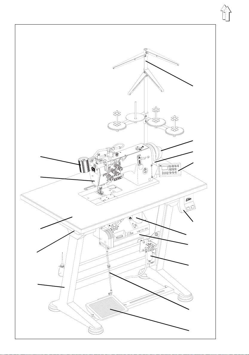
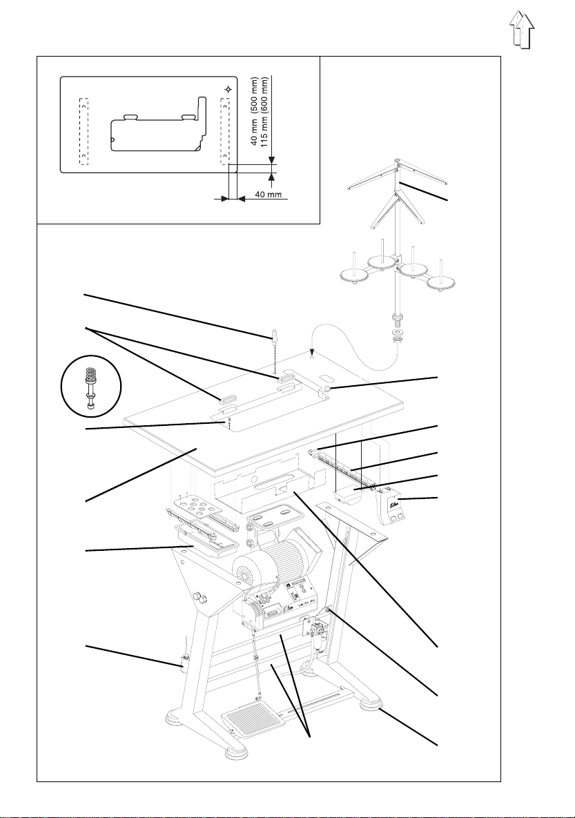
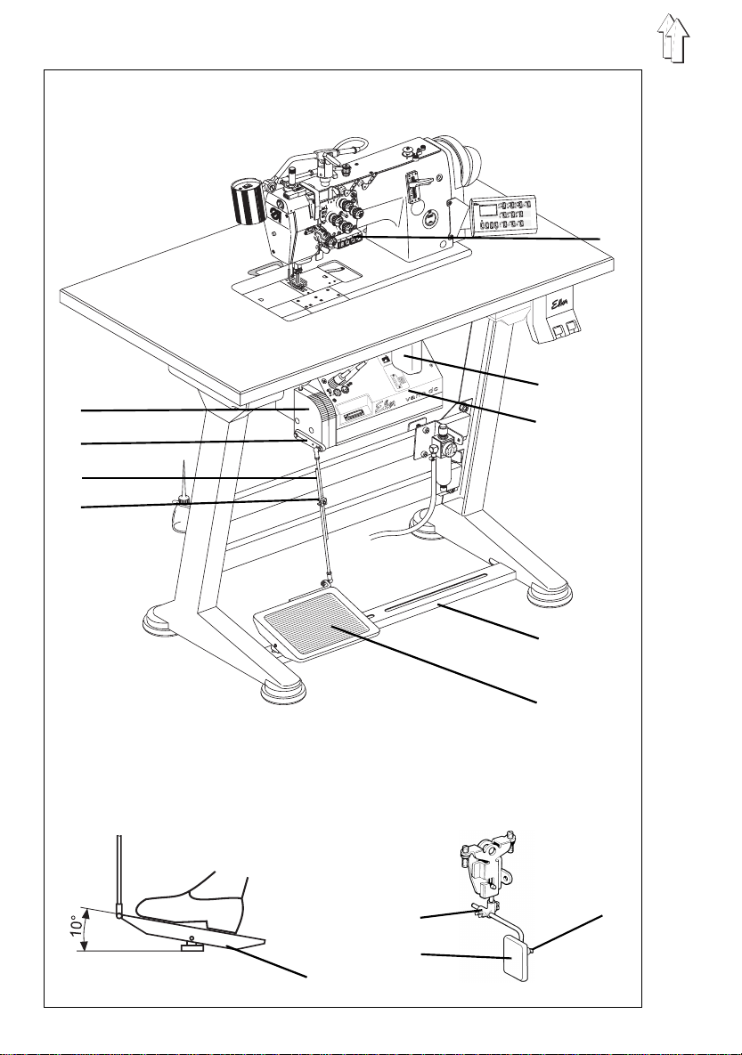
3. Stand installation
3.1 Installing stand parts
–
Install individual parts of the stand as shown in the illustration.
–
Slip-on the ava i l able stand feet 15.
–
Loosen slight l y the screws 14 on both lateral and transversal struts 16 and ensure
that the st and stands saf el y.
The stand should rest on the ground with all its four feet!
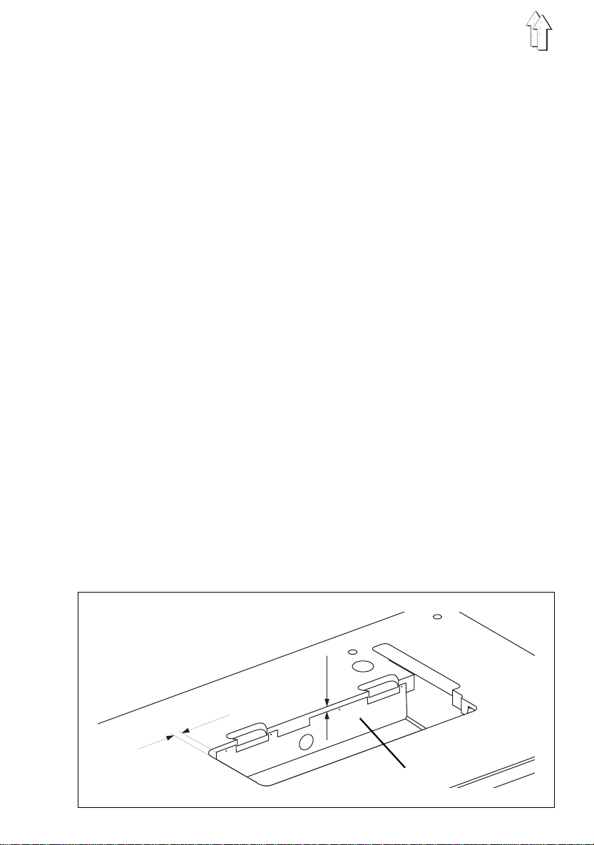
3.2 Completing table top and f astening t o the stand
–
Insert
machine head support 1
–
Insert the
and screw up .
–
Insert
–
Pull-in
–
Screw
–
Screw
–
Screw
–
Screw the
cable duct
–
Screw the
–
Fasten the
(For distan ce, see the sketch., nai l s i n the access ories)
–
Fasten the
the sketch)
–
Introduce the
nuts and shims .
Fit and align thread reel holder and unwind er arm.
The thread re el holder and the unwinder arm should be vertically superposed..
–
Screw the holder for the
hinge bottoms 2
rubber corner 8
rest plugs 3
drawer 5
main switch 12
cable duct 10
holder 9 for the strain relief of the connec tion c ables behind the
10 under the table top.
sewing lamp transformer 11
oil collector 13
table top 4
thread unwinder 7
.
and slip-on pressure spring.
with its holders on the left under the table top.
on the right under the table top.
behind main switch 12 under the table top.
on the stand by wood screws (B8 x 35).(for position, see
into the bore-hole of the table top.
for the machine he ad into the recesses of the table top 4
(additional e quipment) under the table top.
in the table t op recess by na i l s.
into the bore-hole in the table topand fasten by
oil can 6
to the left stand strut.
30 mm
25 mm
13
5
1
2
3
5
4
6
6

3.3 Setting working height
The working height is adjustable between 750 and 900 mm (measured from the upper
edge of the ta bl e top).
–
Loosen the screws 4 on both stand struts.
–
Adjust the table top horizontally for the desired working level.
For avoiding tilting, pull out or push in the table top equally on both sides.
–
Retighten both screws 4.
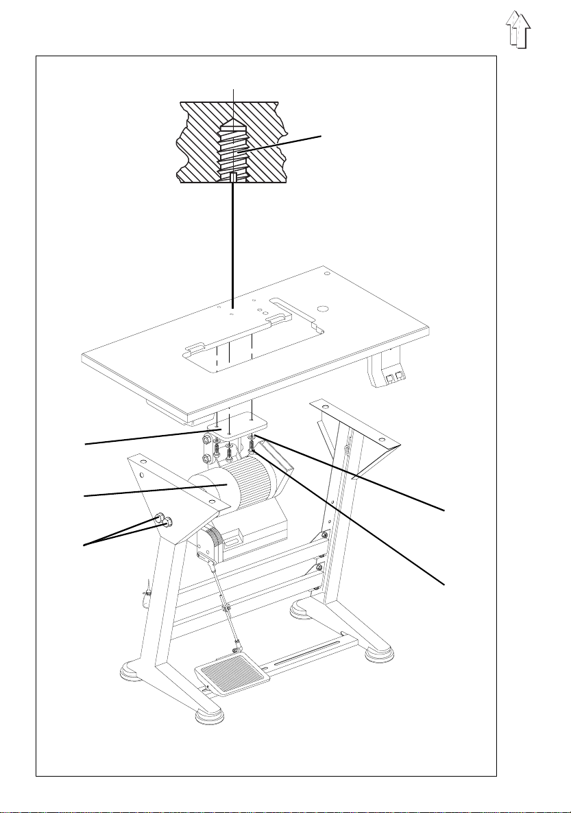
4. Installing and connecting sewing motor
4.1 General
Motor package
Under the ref. no. 9889 038201 8 the
package, incl uding follow i ng elements:
–
Sewing motor DC 1600 / DA82GA 3239
–
Main switch with connect ion cables
–
Control panel
–
Pedal linkage
–
Belt pulley
–
V-belt
–
Connection diagram
–
Fastening and connection material.
381 - 382
will be supplied with a complete motor
4.2 Fitting sewing motor under the table top
–
Fasten the sewi ng motor 3 wi t h its base 2 to the underside of the table top.
Turn the 3 hexagon screws 6 (M8x 35) with the shi ms 5 into the nuts 1 of the table
top.
7
1
2
3 4 5
6 7
8 9
8

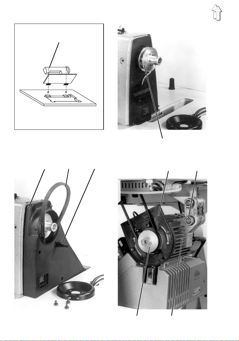
5. Installing machine head
5.1 Insert machine head
–
Insert machine head 1 into the cut-out of the table top.
5.2 Fitting the keys
The tension plate has 3 threaded holes for fastening the keys.
–
Fasten the key 11 to the tension plate by 2 screws as shown in the illustration on
side 10. Two screws are included in the accessories.
2 positions are possible. In the right hand position there is more space at the lever
for connecting and disconnecting the needles.
–
Remove the bobbin cover and pass the incoming cable through its duct.
–
Pass the plug through the table top cut-out and introduce into the bush B3 of the
drive controller.
5.3 Placing and tensioning the V-belt
Remove the safety devices
–
Remove the belt guard cover 6 from the sewing motor.
Place V-belt in position and fit belt guard 3 on the machine head
–
Fasten belt pu l ley 8 (in the acc e ssories) on the shaft of th e sewing motor.
–
Place the V-belt 4 through belt guard on the belt pulley 2 of the machine head.
–
Pass the V-belt 4 down through the cut-out in the table top.
–
Tilt the machine head backwards.
–
Place the V-belt 4 onto the belt pulley 8 of the sewing motor.
–
Return the machine head into its initial position..
When tilting, the belt guard should freely enter the cut-out in the table top.
–
Screw up the belt guard on the machine head.
Tensioning the V-belt
–
Loosen the sc rew 7 on the base of the sewing motor.
–
Tension the V-belt by swi nging the sewing motor 9.
When the ten si on of the V-belt is correct and when t he belt is pressed in its middle
(without any excessive force) it must yield inwards about 10 mm.
–
Re-tighten t he screws 7.
9
variocontrol 720
0
9
8
7
6
5
4
3
21
+
E
P
11
I
0
5
1
6
2
3
4
7
1 Setpoint generator
6 Sewing motor with control box
10
8
9
10
5
8

Fitting the belt guard on the sewing motor
–
Adjust the sa f e t y devices of the belt guard 6 (adjustable cams or square s,
depending on the motor typ e) as follows (see page 8):
After tilting the machine head, the V-belt 4 (seepage 8) must still rest on its pulley.
See also the available operating instructions of the motor manufacturer!
–
Replace the cover of the belt guard 6 (see page 8) and f asten it by screws.
5.4 Fitting the pedal
–
Fasten the pedal 8 to the stand strut 7.
–
For ergonomic reasons, adjust the pedal 8 sideways as fol l ows:
The middle of the pedal must s tand more or les s under the needle.
The stand strut contains l ongitudinal h o l es for the adj ustment of t he pedal.
–
Screw the spherical bolts from the middle into the
–
Hang-in pedal rods 3.
–
Loosen slight l y screw 4.
–
Adjust the height of the pedal rods 3 as follows:
The released pedal 8 should ha ve an inclinati on of about. 10°.
–
Re-tighten s crew 4.
bore-hole of the lever 2.
front
5.5 Fastening the knee lever
The knee lever 5 is used for mechanical lifting of the sewing feet.
–
Hang-in knee l e ver 5.
–
Loosen the sc rews on the joint 9 .
Adjust the knee lever so that it can be conveniently operated by the right knee.
Re-tighten the screws on the joint 9.
–
Loosen screw 1 0 .
Adjust knee pad.
Re-tighten screw 10.
NOTE !
Remove the knee lever 5 bef o re tilting the machine he ad.
11

variocontrol 720
P
+
E
7
45
1
0
98
6
32
12
3
12
5
4

5.6 Fitting the control panel
The machine head provides 2 threaded holes for fastening the control panel.
–
Fasten the external control panel 2 by a square and 2 screws at a side of the
sewing machine head.
–
Lead the connection cable of the contro l panel 2 through the table top cut-out and
pass it down.
–
Introduce the plug of the connection cable into the bush
controller.
B776
of the drive
5.7 Fitting the sewing lamp
NOTE!
The sewing lamp will be supplied with current also when
the main switch is turned off.
–
Stick the adhesive label with the safety indication to the front of the main switch.
–
Remove the bobbin cover.
–
Fasten the holder 3 to the bobbin cover by the screw 4 and the toohted washer 5
(see picture).
–
Place the sewing lamp.
–
Install the incoming cable in its duct.
–
Lead the connection cable through the hole in the table top and pass it down.
–
Fasten the sewi ng lamp tran sformer by chip board screws to the table top.
–
Fasten the connection cable by cable binder under the table top.
–
Connect the incoming cable to the sewing lamp transformer by a plug-in connector.
13

6. Electrical connection
6.1 General
NOTE !
Any work on the electrical equipment of t he special sewi ng
machine should be carried out exclusively by qualified
electricians or by accordingly instructed persons.
The mains plug must have been pulled out!
It is absolutely necessary to note the Operating
Instructions of the manufacturer, supplied together
with the sewing motor!
Connection package and grounding set
The electrical connection package and the grounding set are included in the
accessories of the special sewing machine.
The connection package includes all parts that are necessary for the electrical
connection of the sewing machine head to the sewing motor.
The grounding set serves for grounding the sewing machine head.
For connecting, see chapter 6.7.
6.2 Checking nominal voltage
NOTE !
The rated voltage and the nominal voltage, stated on the
rating plate, must agree.
The direct current drives, where used, are driven by single-phase alternating voltage.
For avoiding overloading of a single phase when connecting several machines to a
three-phase m ains, please note the followi ng:
The connections of the indivi dual machines mu st be evenly dist ri buted to the phases of
the three- phase mains (fo r cabling, see the circuit d i agram).
6.3 Connecting the sewing motor
–
Pass the inco m i ng cable of th e m ain switch th rough the cabl e duct to the s ewing
motor.
–
Connect the commutation transmitter and the setpoint generator (pedal).
–
Pass the mains cable of the ma i n s wi tch through the cable duct an d through the
holder.
–
Secure the mains cable by a s train relief cl amp.
14

6.4 Connection bushes on cont rol box
Connection bush Assignment
B1
B2
B3
B4
B5
B18
B80
B776
ST2
Positioner
Commutation transmitter for DC motor
Key block (on sewing ma chine arm)
not assigned!
not assigned!
not assigned!
Setpoint generator (pedal)
Control panel Variocontrol
Inputs and out puts (sewing mac hi ne head)
15

2
3
1
4 5 6 7
6.5 Establishing cable connectio ns
The electrical connections to t he machine head are passed th rough the central plug-in
connector 1.
–
Introduce the plug into the bush of the sewing machine head.
–
Pass the plug through the table top opening and introduce into the bush
drive controller.
ST2
of the
6.6 Installing the positioner
–
Slip the posit i oner 3 onto the handwheel flan ge.
The slot 6 on th e positioner housing must catch over the anti-rotation ele m ent 5 on
the belt guar d.
–
Tighten both threaded pins 2 on the position transmitter ring 4.
–
Lead the connection cable 7 through the table top bore-hole and pass it down.
–
Introduce the plug of the connection cable into the bush B1 of the drive controller.
16

6.7 Equipotential bond ing
1 2
The grounding cable 1 (in the accessories) guides the stat i c charges of the machine
head via the sewing motor to the ground.
–
Fasten the cable lug of the grounding cable by the screw (M4) and by the shim to
the base of the sewing motor.
–
Pass up the grounding cable.
–
Fasten the grou nding cable 1 by f l at connector 2 to the machin e base plate.
17

6.8 Checking the direction of rotation
NOTE !
It is absolutely necessary to check the direction of rotation
of the sewing motor prior to putting the special sewing
machine into operation.
Damages can result if the special sewing machine is
started to run in the wring direction of rotation.
The arrow in the illustration shows the proper direction of rotation (
rotation)
The special sewing machines, that are supplied fully assembled, have been factory-set
for the
If the special sewing machine is supplied by single components, check the direction of
rotation.
The direction of rotation is set on the control panel by means of the parameter
(drE).
For checking the di rection of rota t i on:
–
–
–
–
.
counter clockwise rotation
Introduce the mains plug.
Turn on main switch.
Call on the control panel the parameter
The parameter must be set to the value " 1 " (counter clockwise rotation).
If required, correct the parameter value.
NOTE !
Following a change of the direction of rotation, the
positions must be programmed once again.
(when looking at the belt pull ey.
of the technician level.
F-161
counter clockwise
F-161
18

6.9 Checking the positionin g
Reference position
The reference position is the starting point for all factory-set positions. In the reference
position, the point of the lowered needle stands level with the top of the throat plate.
Position 1
The 1st position serves for starting the cutting process if the sewing machine is supplied
with a thread cutter. The sewing machin e i s then 2 mm behind its lower dead point.
Position 2
In the 2ne position, the thread take-up lever must be in its upper position.
Checking the positioning
After thread cutting, the sewing machine must stop in the 2nd position (thread take up
lever in upper position).
–
Turn on main switch.
–
Lower the pedal briefly forwards.
–
Lower the pedal backwards completely and hold it lowered.
The thread will be cut.
The sewing machine will stop in the 2nd position (thread take-up lever in upper
position).
–
Check whethe r the thread t ake-up lever st ands in its upper dead position.
–
Normally, here ends the checking process. Should it be necessary to correct the
factory setting, proceed for programming the positions as follows.
6.10 Setting the positions
It is necessary to proceed to a new setting of the position transmitter after following
operations:
–
Fitting the position transmitter when installing the special sewing machine
–
Removing the position transmitter
–
Replacing the position transmitter
–
Replacing th e complete dri ve controller
The digital position trans m i tter does not require any me chanical adjustments.
It is only necessary to set the reference position when taking the machine into service
for the first time.
The machine positions are sensed by steps (increments) by the position transmitter and
they are shown by the display. One rotation of the handwheel corresponds to 512 steps.
The change of the display is done by 2 steps. A change from one display value to the
other corres ponds consequ ently to a rotation angle of about 1,4°.
The angle position of the positions 1 and 2 in respect top the reference position is
defined by a certain number of increments.
19

Programming steps:
1. Calling up programming mode
-
Turn off main switch.
-
Operate the key "P" and hold it op erated.
-
Turn on main switch.
The display will show "
-
Release the key "P".
2. Changing over to the tec hnician level
-
Enter code number "
-
Operate the key "E".
The controller will change over to the technician level ".
The display will show the parameter no. "
-
If a wrong code number is entered, the display will show "
Enter again.
3. Programming reference position
-
Enter parameter number "
-
Operate the key "E".
The display swill show the parameter "
"
" (Service routine 1).
Sr1
The LED above the key "F" will be blinking.
-
Operate the key "F".
The display will show "
-
Turn the handwheel until the reference position is attained (Needle point flush
with the throat plate level).
-
Operate the key "P".
The position set will be memorised.
4. Programming position 1
-
Enter parameter no. "
-
Operate the key "E".
The display will show the parameter "
"
" (Service routine 2).
Sr2
The LED above the key "F" will be blinking.
-
Operate the key "F".
The display will show "
Pos1 = 151 , Pos1a = 200
-
Turn the handwh eel until the 1st position is attained.
1907
171
".
C-0000
" by the digital keys "1...0".
F-100
" by the digital keys "1...0".
170
" together with the code designation
F-170
Position 0
" by the digital keys "1...0".
Position 1
".
" together with the code designation
F-171
" and the respective number of increment s.
".
C-0000 Info F1
".
5. Programming 2nd position
-
Operate the key "E".
The display will show "
Pos2 = 460 , Pos2a = 510
-
Turn the handwheel until the 2n d position is att ai ned.
Position 2
" and the respective number of increment s.
20

6. Parameter setting
Following parameters must be set before putting the mach i ne into operation.
(see also the parameter sheet 9800 130012 PB05)
–
F-111
–
F-115
–
F-119
–
F-190
–
F-191
–
F-202
7. Leaving correction mode
-
8. Memorizing the setting
-
-
-
n2 = 2500 upper limit of the maximum speed
n6 = 250 Softstart speed
nST = 2 Speed graduation slightly progressive
iFA = 300 Engagement angle FA
FSA = 100 Disengagement delay of the thread tension release
br1 = 5 Braking effect
Operate the key "P".
Tread the pedal briefly forw ards.
Tread the pedal completely backwards.
The threads will be cut. The sewing feet will be lifted.
The corrected setting will be memorised.
The sewing machi ne is ready to operate.
NOTE !
For terminat i ng the correct ion process it is absolutely
necessary to sew a short distance. This will finally
memorise the modified setting.
If no sewing is done, the setting will be lost after turning off
the main switch.
21

I
0
1
22
3
6
4
8
2
10
4
5
2
4

7. Pneumatic connection
NOTE !
A perfect function of the pneumatic elements will only be
ensured if th e l i ne pressure ran ges between 8 an d 10 bar.
The service pressure of the s pecial sewing m achine
amounts to
Pneumatic connection package
Under the ref. no. 0797 003031 you can order a pneumatic connection package for
stands with c om pressed air conditioning unit.
It includes following parts:: - Connection hose, 5 m long Ø = 9 mm
- Hose nozzles and hose binders
- Coupling socke t and coupling p l ug
Connecting compressed air conditioning unit
–
Fasten the compressed air conditioning unit 1 to the stand strut by a square, by
screws and by a shackle.
–
Connect the compressed air conditioning unit to the compressed air line by the
connecting hose 2 ( Ø = 9 mm) and by the hose coupling R1/4"
Connecting the compressed air conditioning unit to the sewing mac hine head
–
Connect the hose 4 (in the accessories) wi t h the distribution plate on the machin e
head.
6 bar
.
Setting the service pressure
Set the service pressure to
It is shown by the pressure gauge 5
–
For setting the service pressure, pull up the rotary handle 3 and turn it.
Increase t he pressure = by turning th e rotary handl e 3 clockwise
Reduce the p ressure = By turning t he rotary handle 3 counter clockwise 3
6 bar
.
23

variocontrol 720
E
P
7
45
1
+
0
98
6
32
1
3
2
24
4

8. Oil lubrication
Caution: Danger of bodily injuries !
Oil can cause skin irritations.
Avoid longer contacts with the skin.
Wash the contaminated skin thoroughly.
ACHTUNG !
The handling an d the disposal o f the mineral oil i s
subjected to legal rules.
Take the used oil to an authorised disposal centre.
Protect the env i ronment.
Take care not to spill any oil.
For replenishing the oil container use exclusively the oil quality
ESSO SP-NK 1 0
–
Viscosity at 40° C : 10 mm2/s
–
Flash point: 150 °C
ESSO SP-NK 1 0
following reference numbers:
2 litre container: 9047 000013
5 litre container: 9047 000014
Lubrication of the machine head
–
Fill the container with oil up to the mark "
Hook lubrication
–
Lubricate the points 2 and 3 by some drops of o i l .
–
Check whethe r the felt 4 under the hook drives is sufficiently lubricated.
If necessary, lubricate the felt 4 at the open right and left corner when installing.
The toothed wheels of the ho ok drive have oil f elts, supplie d with oil by the f el t 4.
The felt 4 must be in contact w i t h the oil felts of the hook driv e.
Oiling wicks and felt parts
–
When installing and after longs periods of standstill oil slightly the wicks and the
felt parts of t he sewing machine.
or an equal oil grade with following specifications:
can be obtained from sales centres of
max.
DÜRKOPP ADLER AG
".
under
25

9. Sewing test
Following the installation, proceed to a sewing test!
–
Introduce the mains plug.
Caution: danger of bodily injuries !
Turn off main switch.
Switch off the sewing machine before threading the needle
and the hook.
–
Thread the bo bbin (see the Operating Instructions).
–
Turn on main switch.
–
Fill the bobbin at low speed.
–
Thread the needle and the hook (see the Operating Instructions).
–
Select the material to be sewn.
–
Conduct the sewing test f i rst at low speed and then at an increasin gl y higher
speed.
–
Check whethe r the seems ar e m eeting the re quirements.
If the requirements are not met, modify thread tensions (see the Operating
Instructions).
If required, check and, if necessary, also correct the settings specified in the
Service Instructions.
26
 Loading...