

Page 1

Contents Page:
Service Instructions Cl. 381/382
1. General
1.1 Gauge set . . . . . . . . . . . . . . . . . . . . . . . . . . . . . . . . . . . . . . . . . . . . . . . 4
1.2 Description and adjustment of the integrated adjusting disk . . . . . . . . . . . . . . . . . . . 4
1.3 Position of the integrated adjusting disk in relation to the arm shaft . . . . . . . . . . . . . . . 5
1.4 Position of the lower toothed belt pulley . . . . . . . . . . . . . . . . . . . . . . . . . . . . . . . 6
2. Distance between the needle bar and the cloth presser bar
3. Position of the needle in the stitch hole . . . . . . . . . . . . . . . . . . . . . . . . . . . . . 8
4. Synchronism of the needle and of the lower feed . . . . . . . . . . . . . . . . . . . . . . . . 9
5. Feed dog height . . . . . . . . . . . . . . . . . . . . . . . . . . . . . . . . . . . . . . . . . . . 10
6. Aligning the feed dog . . . . . . . . . . . . . . . . . . . . . . . . . . . . . . . . . . . . . . . . 11
7. Position of the lifting eccentric . . . . . . . . . . . . . . . . . . . . . . . . . . . . . . . . . . 12
8. Upper puller feed
8.1 Synchronism of the lower feed and upper puller feed . . . . . . . . . . . . . . . . . . . . . . . 14
8.2 Distance between the puller and the needle . . . . . . . . . . . . . . . . . . . . . . . . . . . . 15
8.3 Puller lifting stroke . . . . . . . . . . . . . . . . . . . . . . . . . . . . . . . . . . . . . . . . . . . 16
8.4 Puller pressure . . . . . . . . . . . . . . . . . . . . . . . . . . . . . . . . . . . . . . . . . . . . . 17
8.5 Fabric repeller . . . . . . . . . . . . . . . . . . . . . . . . . . . . . . . . . . . . . . . . . . . . . 18
8.6 Toothed belt tension of the upper puller feed . . . . . . . . . . . . . . . . . . . . . . . . . . . . 19
8.7 Replacing the puller
9. Needle bar height . . . . . . . . . . . . . . . . . . . . . . . . . . . . . . . . . . . . . . . . . . . 20
10. Sewing foot height and sewing foot lift
10.1 Height of the cloth presser bar . . . . . . . . . . . . . . . . . . . . . . . . . . . . . . . . . . . . 21
10.2 Foot lift, mechanical . . . . . . . . . . . . . . . . . . . . . . . . . . . . . . . . . . . . . . . . . . 22
10.3 Foot lift, electropneumatic (autom. sewing foot lift) . . . . . . . . . . . . . . . . . . . . . . . . 23
10.4 Sewing foot power . . . . . . . . . . . . . . . . . . . . . . . . . . . . . . . . . . . . . . . . . . . 24
11. Thread guiding parts
11.1 Releasing the upper thread tension . . . . . . . . . . . . . . . . . . . . . . . . . . . . . . . . . 25
11.2 Thread tightening spring . . . . . . . . . . . . . . . . . . . . . . . . . . . . . . . . . . . . . . . 26
12. Bobbin winder . . . . . . . . . . . . . . . . . . . . . . . . . . . . . . . . . . . . . . . . . . . . 27
13. Hook adjustments
13.1 Loop stroke and distance of the hook tip to the needle . . . . . . . . . . . . . . . . . . . . . . 28
13.2 Bobbin case lifter . . . . . . . . . . . . . . . . . . . . . . . . . . . . . . . . . . . . . . . . . . . 29
GB
Page 2

Contents Page:
14. Thread cutter
14.1 Adjusting the control cam . . . . . . . . . . . . . . . . . . . . . . . . . . . . . . . . . . . . . . 30
14.2 Adjusting the thread cutter magnet . . . . . . . . . . . . . . . . . . . . . . . . . . . . . . . . . 31
14.3 Adjusting the roller bolt . . . . . . . . . . . . . . . . . . . . . . . . . . . . . . . . . . . . . . . 31
14.4 Timing the knife movement . . . . . . . . . . . . . . . . . . . . . . . . . . . . . . . . . . . . . 32
14.5 Height of the hook shaped knife and lateeral distance to the throat plate . . . . . . . . . . . . 33
14.6 Position of the hook shaped knife in relation to the counter knife . . . . . . . . . . . . . . . . 34
14.7 Cutting pressure . . . . . . . . . . . . . . . . . . . . . . . . . . . . . . . . . . . . . . . . . . . 35
14.8 Adjusting the thread clamp position . . . . . . . . . . . . . . . . . . . . . . . . . . . . . . . . 35
14.9 Thread clamp pressure . . . . . . . . . . . . . . . . . . . . . . . . . . . . . . . . . . . . . . . 36
14.10 Transmission rods for the action of the hook shaped knife . . . . . . . . . . . . . . . . . . . . 37
15. Needle bar crank and disconnectable needle bars
15.1 Removing the needle bar crank . . . . . . . . . . . . . . . . . . . . . . . . . . . . . . . . . . . 38
15.2 Removing a needle bar from the crank . . . . . . . . . . . . . . . . . . . . . . . . . . . . . . . 39
15.3 Stripping a needle bar . . . . . . . . . . . . . . . . . . . . . . . . . . . . . . . . . . . . . . . . 40
15.4 Assembling a needle bar . . . . . . . . . . . . . . . . . . . . . . . . . . . . . . . . . . . . . . . 40
15.5 Fitting the needle bars into the needle bar crank . . . . . . . . . . . . . . . . . . . . . . . . . 41
15.6 Fitting the needle bar crank . . . . . . . . . . . . . . . . . . . . . . . . . . . . . . . . . . . . . 43
16. Changing the sewing equipment . . . . . . . . . . . . . . . . . . . . . . . . . . . . . . . . . 44
17. Changing the toothed belt . . . . . . . . . . . . . . . . . . . . . . . . . . . . . . . . . . . . . 45
18. Lubrication
18.1 Oil circulation . . . . . . . . . . . . . . . . . . . . . . . . . . . . . . . . . . . . . . . . . . . . . 47
18.2 Hook-drive lubrication . . . . . . . . . . . . . . . . . . . . . . . . . . . . . . . . . . . . . . . . 48
19. Sewing motors . . . . . . . . . . . . . . . . . . . . . . . . . . . . . . . . . . . . . . . . . . . . 49
19.1 Sewing motor control unit DA82GA . . . . . . . . . . . . . . . . . . . . . . . . . . . . . . . . . 49
19.2 Sewing motor control unit 6F82FA . . . . . . . . . . . . . . . . . . . . . . . . . . . . . . . . . 49
19.3 Positioning . . . . . . . . . . . . . . . . . . . . . . . . . . . . . . . . . . . . . . . . . . . . . . 49
19.4 Setting the machine specifical parameteres . . . . . . . . . . . . . . . . . . . . . . . . . . . . 49
19.5 Masterreset . . . . . . . . . . . . . . . . . . . . . . . . . . . . . . . . . . . . . . . . . . . . . . 49
19.6 Parameter list . . . . . . . . . . . . . . . . . . . . . . . . . . . . . . . . . . . . . . . . . . . . . 49
20. Maintenance . . . . . . . . . . . . . . . . . . . . . . . . . . . . . . . . . . . . . . . . . . . . . 50
21. Optional equipment
21.1 Thread wiper . . . . . . . . . . . . . . . . . . . . . . . . . . . . . . . . . . . . . . . . . . . . . 51
NOTE !
The pictures shown in the present manual are originating from
different special machine classes or sub-classes.
Please note that your special sewing machine may deviate from the
picture.
Page 3
1. General points
The present Service Instructions 381-382 are describing the
adjustment of the special sewing machine.
381-160161 Twin needle flat bed double lockstitch machine
with disconnectable needles, lower feed and
needle feed, electromagnetic thread cutter
381-160162 as cl. 381-160161, but additionally with an automatic
electropneumatic -
bartacking mechanism and electropneumatic
sewing foot lift
382-160162 as cl. 381-160162, but additionally with puller feed
NOTE !
The actions described in the present Manual should be carried out
exclusively by specialists or by the properly qualified staff. !
Caution: Danger of bodily injuries !
Turn off main switch and disconnect the machine from the pneumatic
supply line when proceeding to repairs, transformations or
maintenance.
Any adjustment work and function tests on the running machine should
be carried out very carefully and noting all safety precautions.
The present Service Instructions are describing in proper sequence
the adjustment of the sewing machine. Please note that the different
adjustment positions are interdependent. Therefore, it is absolutely
necessary to follow the described sequence.
Introduce a new perfect needle before proceeding to the adjustments
of the stitch forming parts.
3
GB
Page 4
1.1 Gauge set
The following seting gauge enables a precise adjustment and checking
of the sewing machine.
Position Setting gauge Ref. no. Use
1 Setting pin 9301 022608 Locking the tracing positions
1.2 Description and adjustment of the integrated adjusting disk
1
3
II
I
V
III
IV
By means of the locking pin 3 and by the disk 1, flanged to the toothed
belt pulley of the arm shaft, it is possible to lock the sewing machine in
all adjustment positions.
The adjusting disk provides for this purpose 5 incisions.
The incision I (loop stroke position) is deeper than the other incisions.
Set in the individual positions:
I The adjusting disk in relation to the groove of the arm shaft crank,
loop stroke,
The distance of the hook tip in relation to the needle, the puller
action moment: the groove of the eccentric on the groove of the
traction rod
13
II 1. Needle position
III 2. Needle position
IV Control cam for the thread cutter
V Needle bar height
Standstill of the feed dog when moving the stitch regulator crank (feed dog at the upper dead point)
Feed dog height
4
Page 5
1.3 Position of the integrated adjusting disk in relation to the arm shaft
NOTE!
All adjustments made by the adjusting disk are only correct when the
setting has been done in compliance with the rules. Following an
adjustment of the arm shaft, check and, if necessary , correct all the
following settings.
Caution: Danger of bodily injuries !
Turn off main switch !
Turn off the sewing machine before correcting the arm shaft position
Rule and control
The machine includes an integrated adjusting disk. It is flanged to the
toothed belt pulley on the arm shaft.
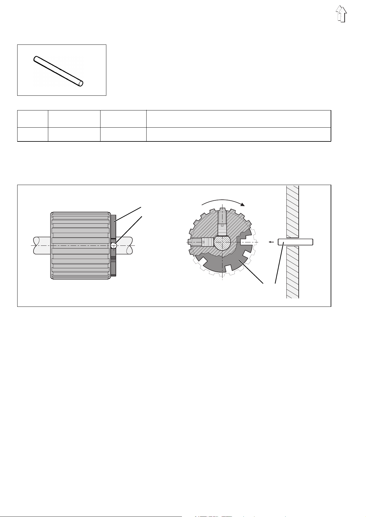
The basic position for the upper toothed belt pulley is defined in such a
way that, when tracing the crank by the tracing pin 3 or by the drill
shaft Ø 5 mm through the borehole X, the groove I of the adjusting disk
can be traced by the tracing pin 3 in the borehole Y.
The first fastening screw, seen in the direction of rotation of the pulley,
stands on the flat surface of the arm shaft (See the illustration).
The groove 2 and the incision I of the adjusting disk must be in
alignment X - Y.
–
Lock the arm shaft by a locking pin or by a pin of Ø 5 mm in
in the groove 2 of the arm shaft crank (through the hole X).
–
It should be possible to insert the locking pin through the hole Y in
pos. I.
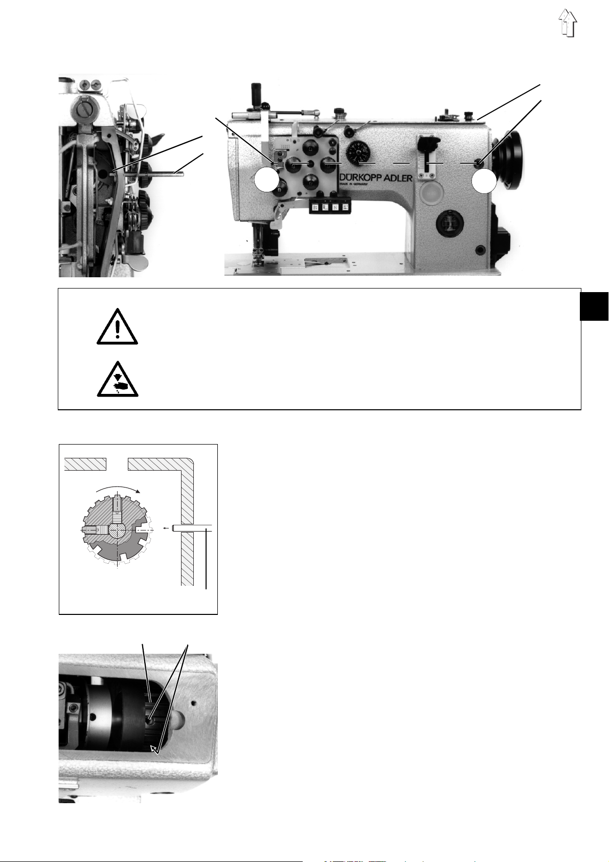
Correction
–
Remove the bobbin winder lid 4.
–
Loosen the screws 6 of the toothed belt pulley.
Introduce the wrench through the arm opening.
–
Lock the toothed belt pulley by the locking pin in position I .
–
Insert a 5 mm thick pin into the tracing hole X and let snap the
groove of the arm shaft crank 2.
–
In the axial direction, the toothed belt pulley 5 must rest against
the cover pin.
Retighten the screws of the toothed belt pulley
(See the illustration p.4).
II
I
V
IV
III
3
Y
X
1
2
3
4
5
56
5
GB
Page 6
1.4 Position of the lower toothed belt pulley
2
1
3
4
Caution: Danger of bodily injuries !
Turn off main switch.
Turn off the sewing unit before positioning the lower toothed belt pulley.
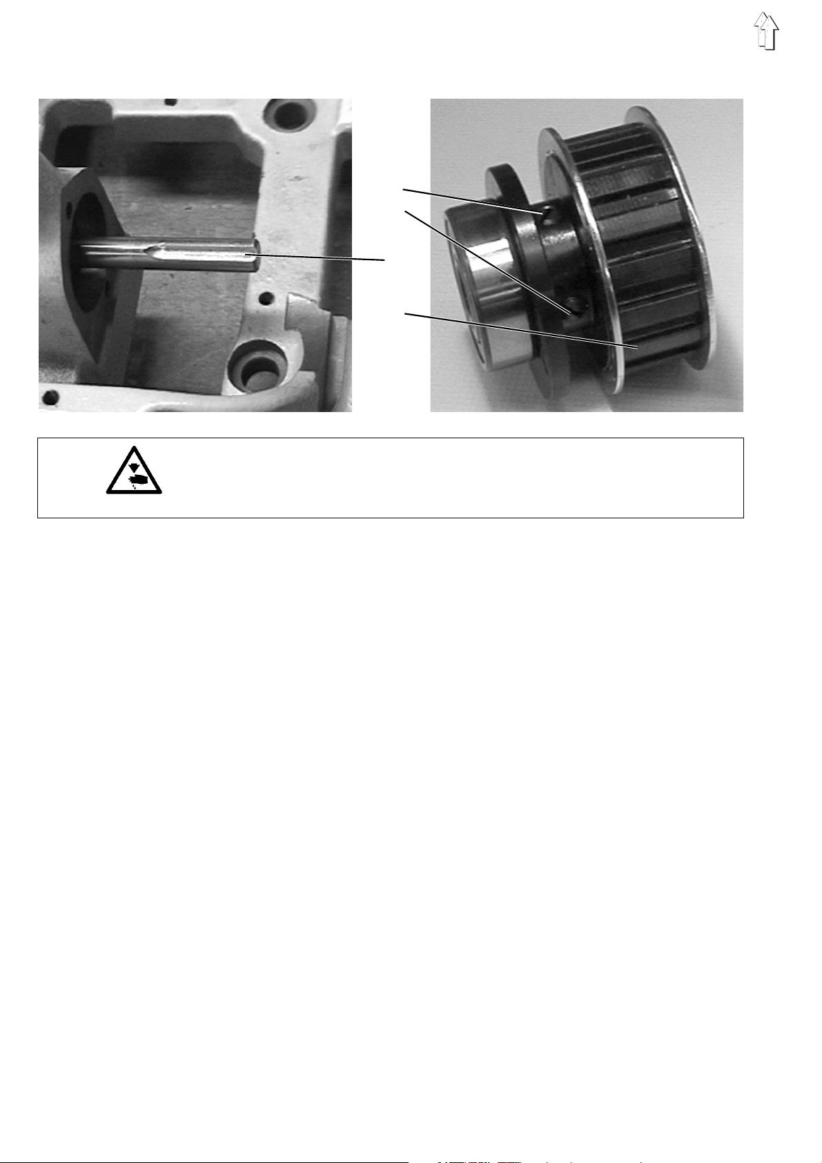
Rule and control
The point of the first screw, seen in the direction of rotation, snaps into
the groove 3 of the lower shaft.
Correction
–
Loosen the threaded pins 1 and 2.
–
Adjust the lower toothed belt pulley 4. The first screw 1, seen in
the direcrtion of rotation, (with the point) snaps into the groove 3 of
the lower shaft.
–
Retighten the threaded pinse 1 and 2.
–
Control and, if required, correct all the settings described
hereinafter.
6
Page 7
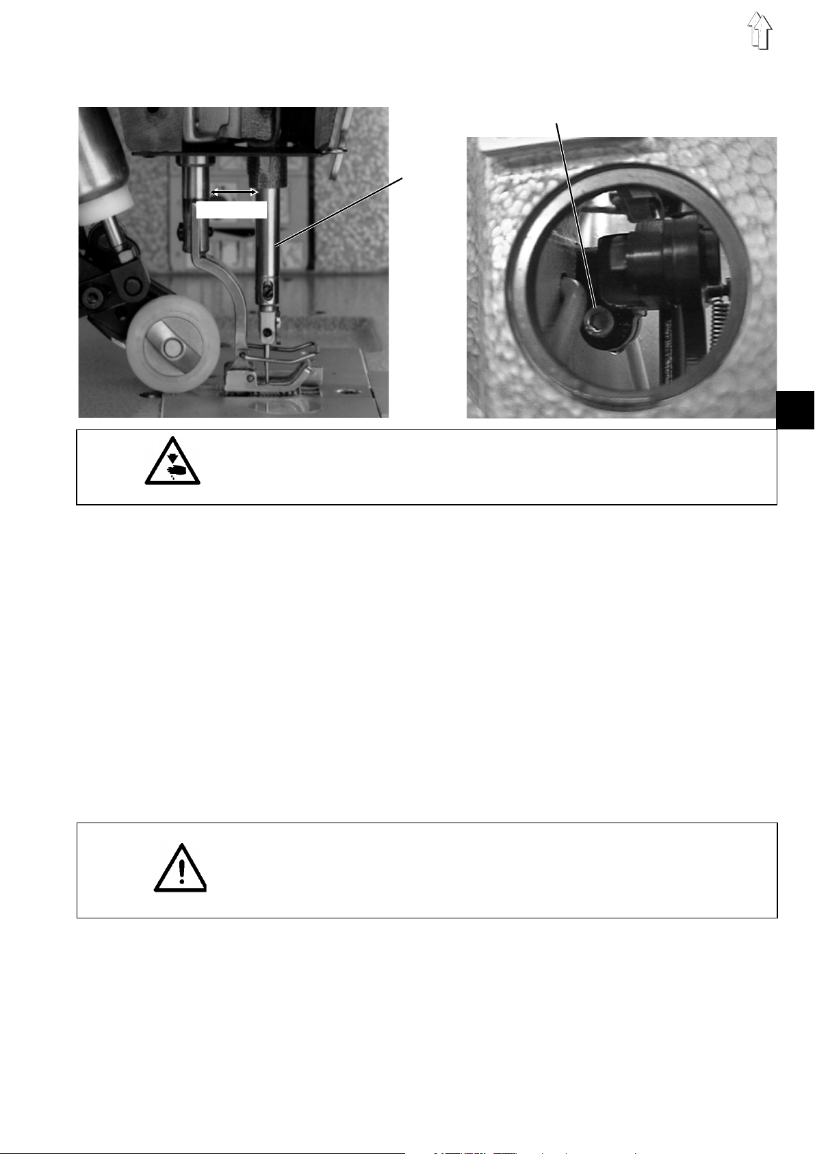
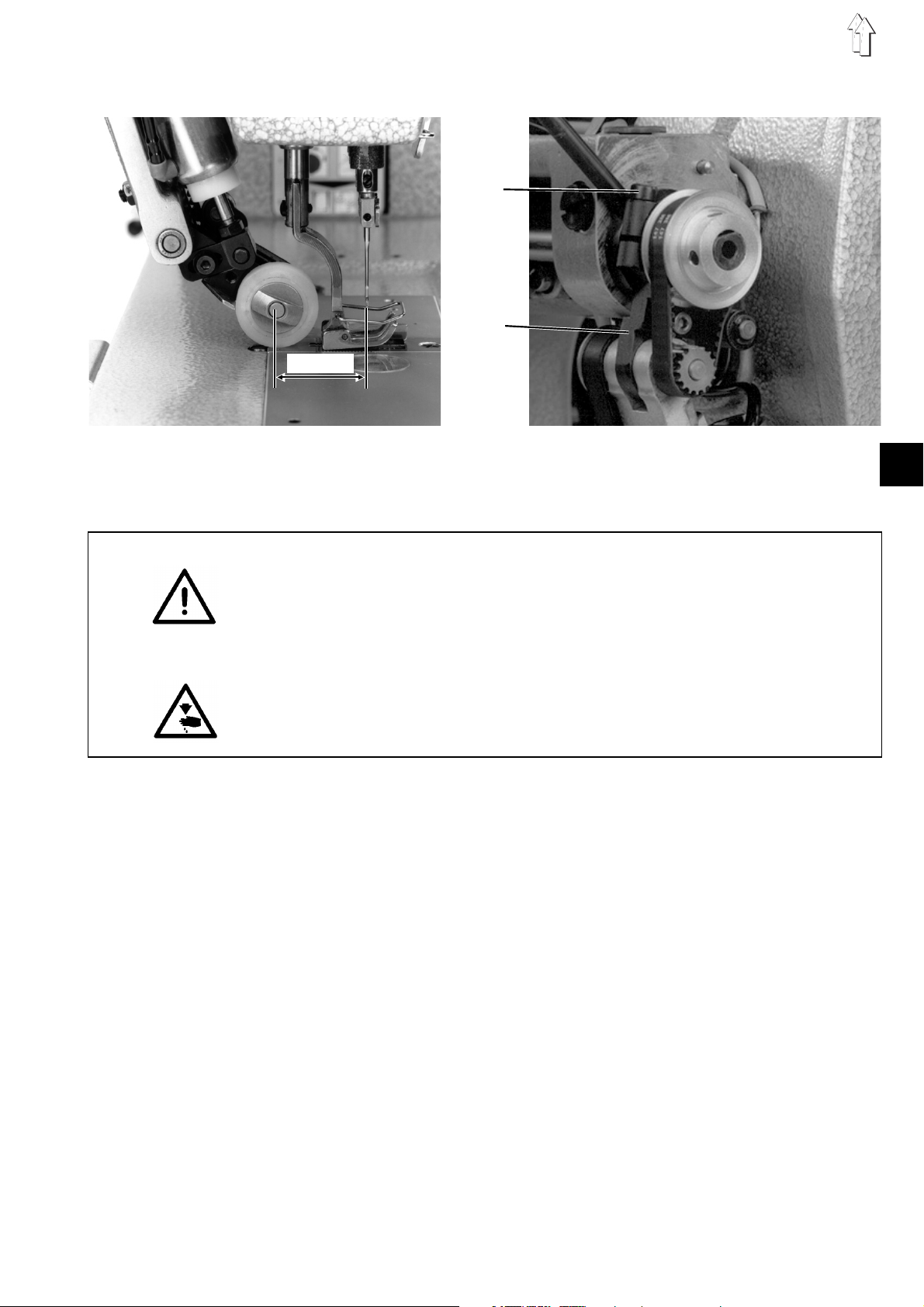
2. Distance between the needle bar and the cloth presser bar
Caution: Danger of bodily injuries !
Turn off main switch !
Turn off the sewing machine before correcting the distance.
Rule and control
When the stitch regulator stands on "0", the distance between the
needle bar and the cloth presser bar should amount to 14,3 mm.
Correction
–
Set "0" stitch length.
–
Remove the cap from the sewing machine arm.
–
Loosen screw 2.
–
Push needle bar crank 1 to and fro until the desired distance is
attained (14,3 mm).
–
Retighten screw 2.
–
Ensure that the needle feed shaft does not present any play in the
axial direction.
–
Replace the cover cap.
–
Proceed to a new adjustment of the feed dog (see chapter 6).
NOTE!
Following the adjustment and having the maximum stitch length, the
needle should not knock in the sewing foot slot nor should the feed
dog touch the throat plate.
Avoid damage to the needles.
14,3 mm
1
2
7
GB
Page 8
3. Position of the needle in the stitch hole
1
2
3
Rule and control
When the dist ance between the needle bar and the cloth presser bar
has been set, the needle should stitch in the middle of the stitch hole.
–
Turn the hand wheel.
–
Check whether the needle stitches in the middle of the stitch hole.
Correction
–
Set stitch regultor lever on "0".
–
Loosen the screws 3 of the clamping block 2.
–
Turn the clamping block on the shaft 1 accordingly
–
Retighten the screws 3
8
Page 9
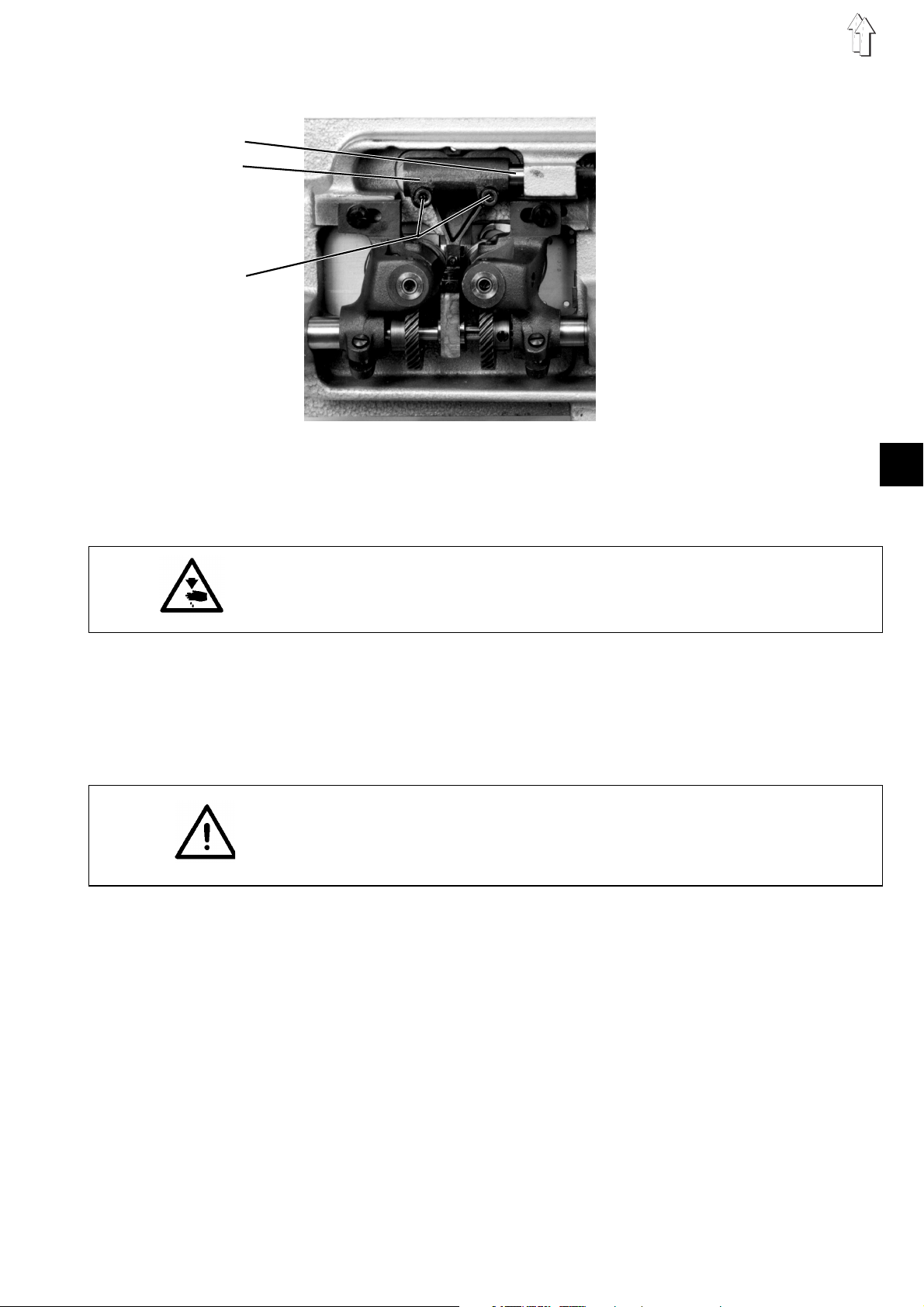
4. Synchronism of the needle and of the lower feed
Rule and control
The needle and the feed dog 1 should advance the material equally
when sewing forwards or backwards, i.e. the needle and the feed dog
should be well timed. The needle should not travel within the stitch
hole of the feed dog..
The needle and the feed dog have been set in the factory to the same
value.
–
Set the maximum stitch length.
–
Check the synchronism by turning the hand wheel..
Caution: Danger of bodily injuries !
Turn off main switch !
Turn off the sewing machine before correcting the needle and the
lower feed
korrigieren.
Correction
–
Remove the sealing cap 5.
–
Loosene the nut 2.
–
Displace the traction rod 4 in the oblong hole of the lever 3
accordingly.
–
Retighten the nut 2.
–
Replace the sealing cap 5.
1
5
2 3 4
9
GB
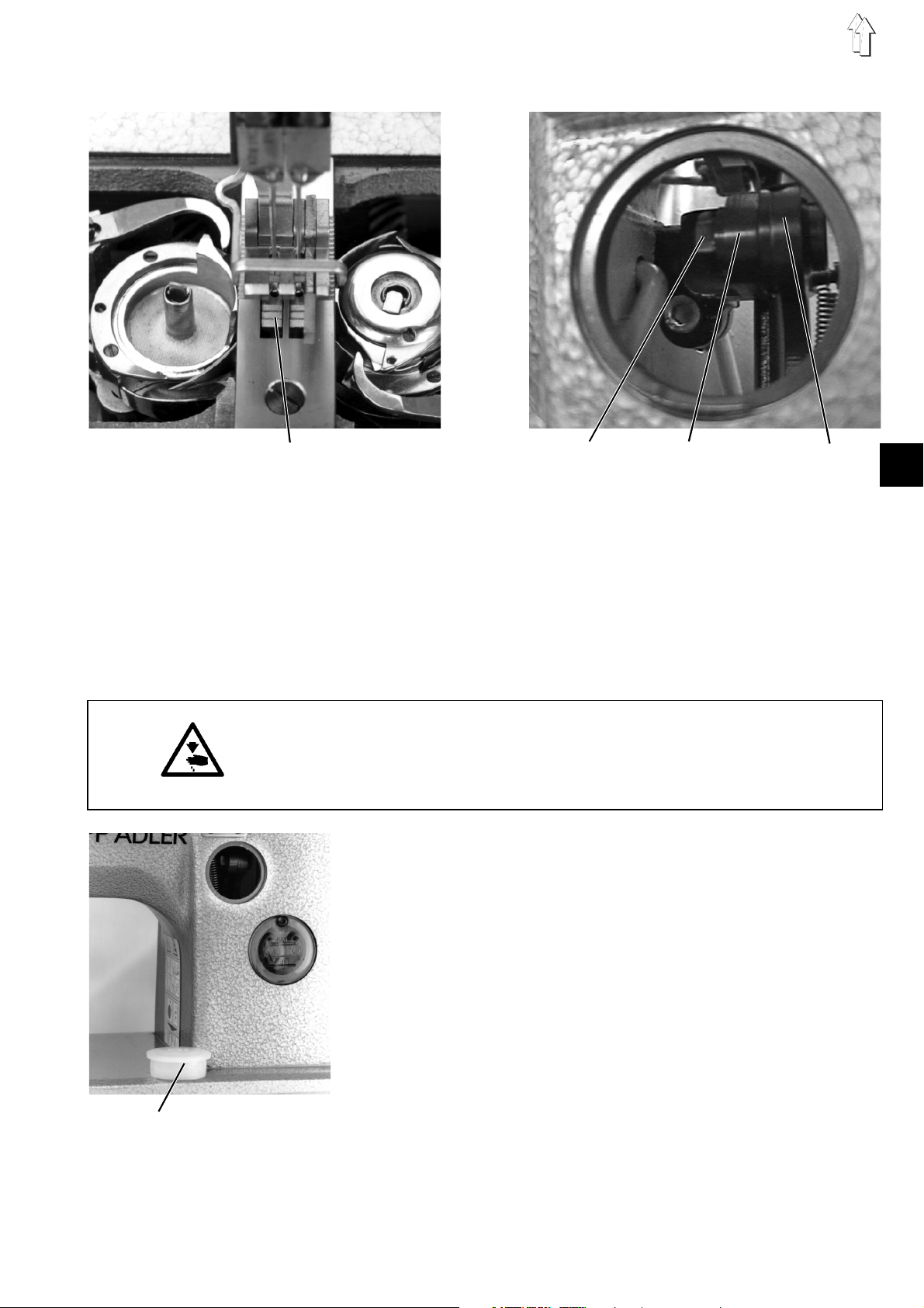
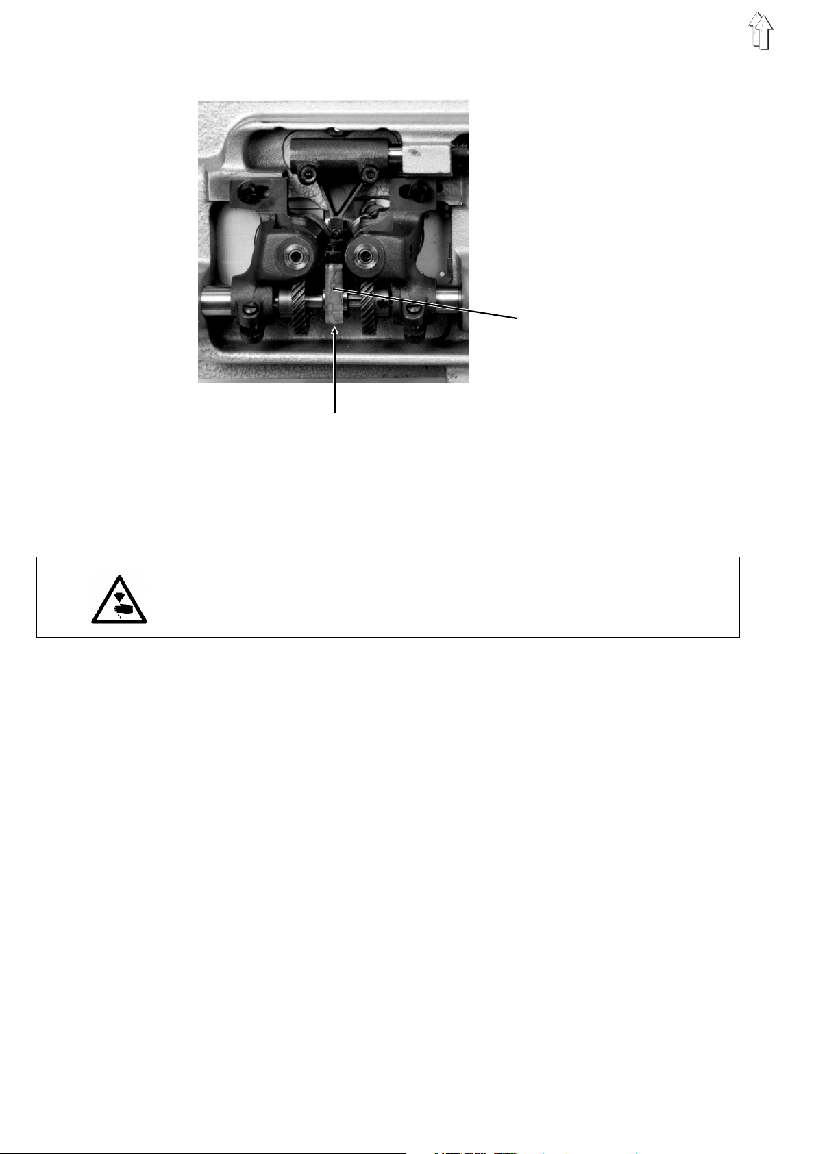
Page 10
5. Feed dog height
1234 56 7
7
4
5
6
Rule and control
For ensuring a safe material feed, the feed dog 10, when being at its
topmost point, should exceed the throat plate surface by 1.1 mm. The
feed dog teeth should be parallel to the throat plate surface.
8 9 10
Caution: Danger of bodily injuries !
Turn off main switch !
Turn off the sewing machine before correcting the lifting eccentric and
the feed dog height.
Correction
–
Lock the sewing machine in V position. (feed dog at its topmost
point).
–
Loosen the screws 6.
–
Remove the throat plate.
–
Turn the supporting screw 2 counter clockwise.
–
Set the feed dog bar higher or loweer
–
Replace the throat plate.
–
Set the feed dog height to 1,1 mm.
–
Retighten the screws 6.
–
After each adjustment, turn the supporting screw at low pressure
against the eccentric fork 1. The lifting eccentric should turn in the
fork 1 easily.
–
Loosen slightly the screws 3.
–
Loosen the counter nut 4.
–
Set the feed dog parallel to the throat plate surface by turning the
seting screw 5.
–
Retighten the screws 3.
–
Fasten the throat plate. Ensure that the nose 9 of the bobbin case
top snaps into the recess of the throat plate (also the left side).
–
Retighten the counter nut 4.
10
Page 11
6. Aligning the feed dog
Rule and control
With the stitch length being set to its maximum value, the feed dog
should have the same distance to the throat plate recess at the front
and at the rear, and laterally it should stand in the middle.
Caution: Danger of bodily injuries !
Turn off main switch !
Turn off the sewing machine before correcting the feed dog.
Correction
–
The distance between the presser/ skipping bar and the needle bar
should be set correctly.
–
Loosen the screws 3 of the clamping block 2.
–
Turn the clamping block on the shaft 1 accordingly.
–
Retighten the screws 3.
NOTE!
Ensure for the above adjustment that the needle stitches in the middle
of the feed dog stitch hole (see chapter. 3).
1
2
3
11
GB
Page 12
7. Position of the lifting eccentric
Access to the fastening screw of the lifting eccentric
Rule and control
The top of the feed dog should stand 0,1 - 0,2 mm above the throat
plarte surface when the point of the needle reaches the throat plate
(smooth sewing / avoiding needle breakage during the bartacking
action
5
Caution: Danger of bodily injuries !
Turn off main switch !
Turn off the sewing machine before correcting the position of the lifting
eccentric.
Correction
–
Loosen the fastening screw of the lifting eccentric.
–
Turn the eccentric 5 on the loweer shaft.
–
Retighten the fastening screw of the lifting eccentric.
12
Page 13
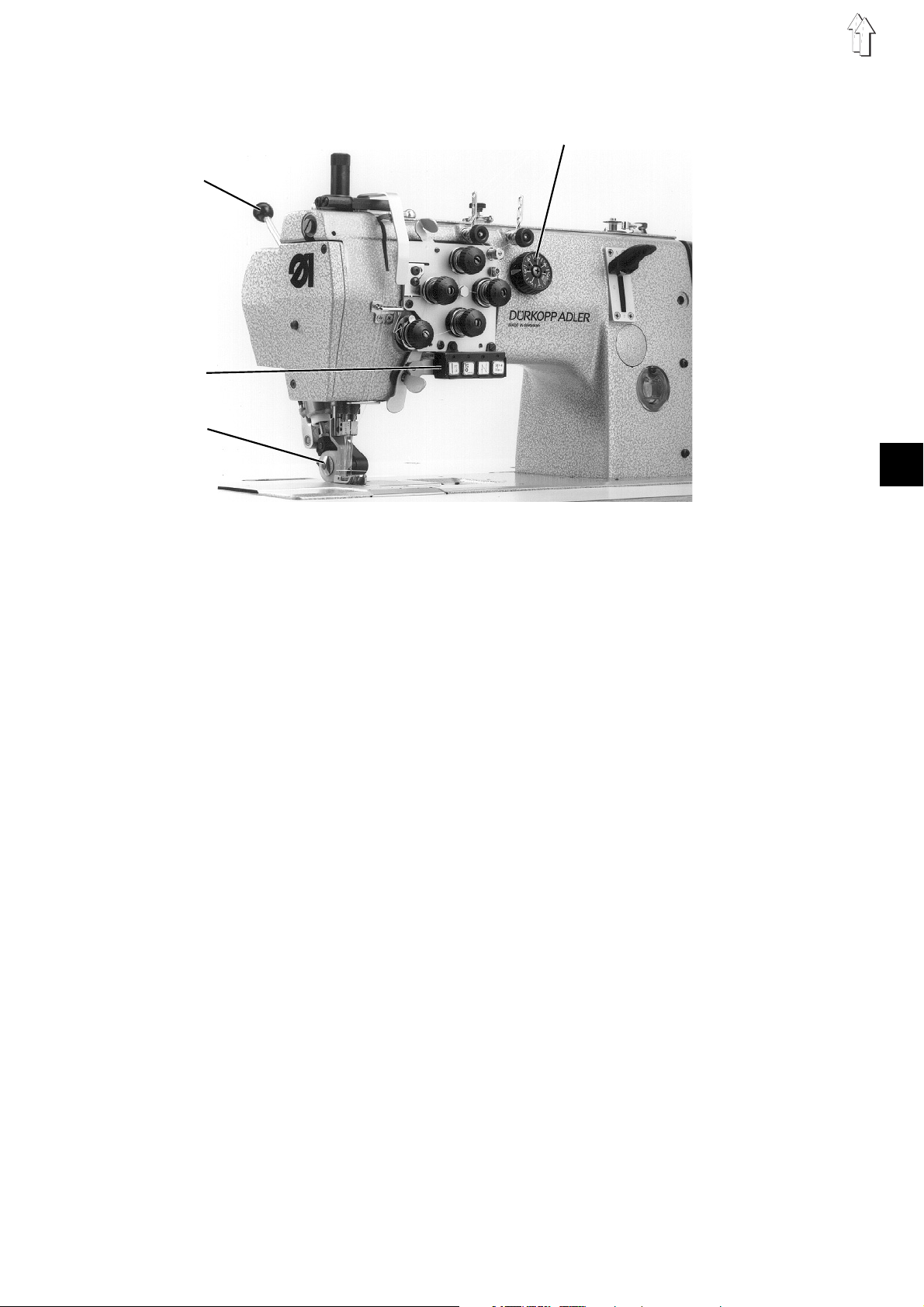
8. Upper puller feed (only in 382)
Rule and control
The puller 3 is lifted automatically when lifting the sewing foot and
when bartacking the seam.
The function must be entered on the control panel.
See Installation Instructions, chapter 12.
The maximum feed length of the intermittent upper puller feed
amounts to 7 mm. The feed length can be set by the wheel 4
independently from the lower feed.
1 = Hand lever Swivelling the roller in and out of the sewing area
2 = Key Lifting or lowering the puller automtically
The function is set on the control panel
Correcting the lifting and lowering function
–
Set the desired function on the control panel.
4
1
2
3
13
GB
Page 14
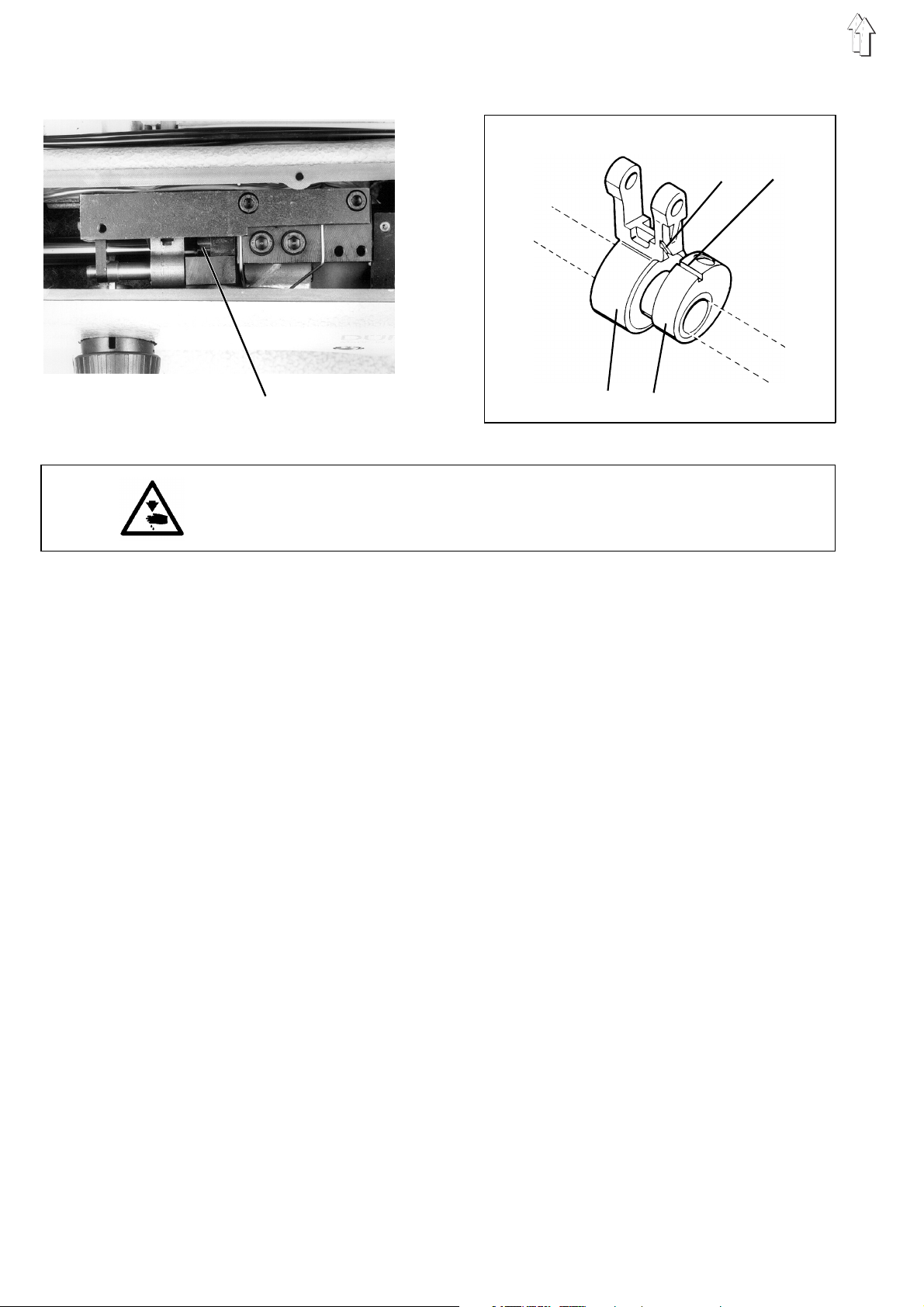
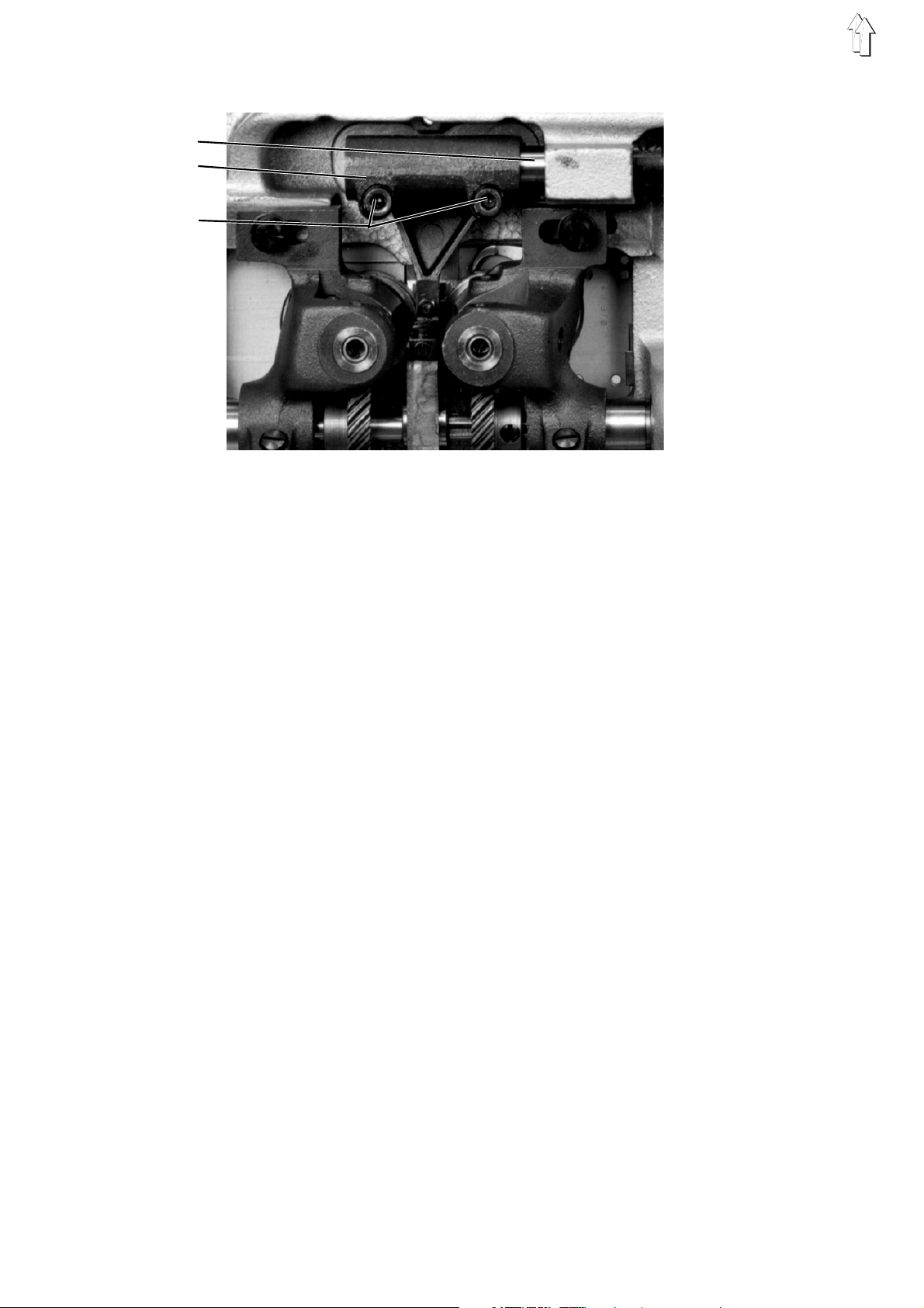
8.1 Synchronism of the lower feed and of the upper puller feed
34
4
Caution: Danger of bodily injuries !
Turn off main switch !
Turn off the sewing machine before correcting the synchronism.
Rule and control
The lower feed and the upper puller feed should be well timed.
The movement of the upper feed puller should din no case end before
the movement of the feed dog.
This is necessary to ensure that the material between the sewing foot
and the puller remains under tension, minimising thus the seam ruffing
by the stitch tightening.
–
Remove bobbin winder cover.
–
Lock the machine in position I.
–
The groove 4 of the eccentric 2 ande the groove 3 of the traction
rod 1 must be in alignment.
12
14
Correction
–
Remove the locking pin.
–
Loosen the fastening screw of the eccentric 2.
The eccentric should turn on the shaft easily.
–
Fix the eccentric 2 by a screwdriver.
–
Turn the hand wheel until the groove on the traction rod eye and
the groove of the eccentric flange are susperposed.
–
Note: In this position it is possible to set out the tracing pin in
position I of the adjusting disk.
–
Retighten the fastening screws of the eccentric 2.
–
Check wheher the groove 4 of the eccentric and the groove 3 of
the traction rod coincide.
In the negative, repeat the adjustment.
–
Replace the bobbin winder lid.
Page 15
8.2 Distance between the puller and the needle
Rule and control
In case of the stitch length = "0", the distance between the middle of
the puller and the middle of the needle amounts to 28,5 mm.
NOTE !
When proceeding to a new adjustment of the distance, it is necesssary
to readjust also the upper and the lowere end position !
(See chapter 8.3)
The puller should not knock against the sewing foot at the moment of
the automatic lift!
Caution: Danger of bodily injuries !
Turn off main switch !
Turn off the sewing machine before correcting the distance.
Correction
–
Set stitch regulator on "0".
–
Loosen the swcrew 1.
–
Turn the rocker 2 on the axle.
The distance between the middle of the puller and the middle of
the needle should amount to 28,5 mm.
–
Retighten the screw 1.
1
2
28,5 mm
15
GB
Page 16
8.3 Puller lifting stroke
1
2
3
4
5
Rule and control
The lifting stroke amounts to 7 mm.
The lifted puller should not knock against the sewing foot in the upper
end position.
In the lower end position, followiwng the descent of the puller onto
the throat plate, the rocker 1 should still yield 0,5 to 1 mm before the
stop of the hand lever reaches its end position.
If a steel puller is used, a light gap must still exist in the lower end
position. The steel puller should not rest on the throat plate, because
otherwise the throat plate might be damaged.
Caution: Danger of bodily injuries !
Turn off main switch !
Turn off the sewing machine before correcting the lifting stroke.
Correcting the upper end position
–
Turn the bolt 2.
The slit of the bolt must be parallel to the cylinder axis.
6
7
–
Limit the stroke of the cylinder 3.
By using a 2,5 mm Allan key, set the threaded pin 7
accordingly.
6 = Access to the threaded pin 7
2
Correcting the lower end position
–
Loosen the counter nut 4.
–
Turn the threaded pin 5.
in = for lifting
out = for lowering
–
Retighten the counter nut 4.
16
Page 17
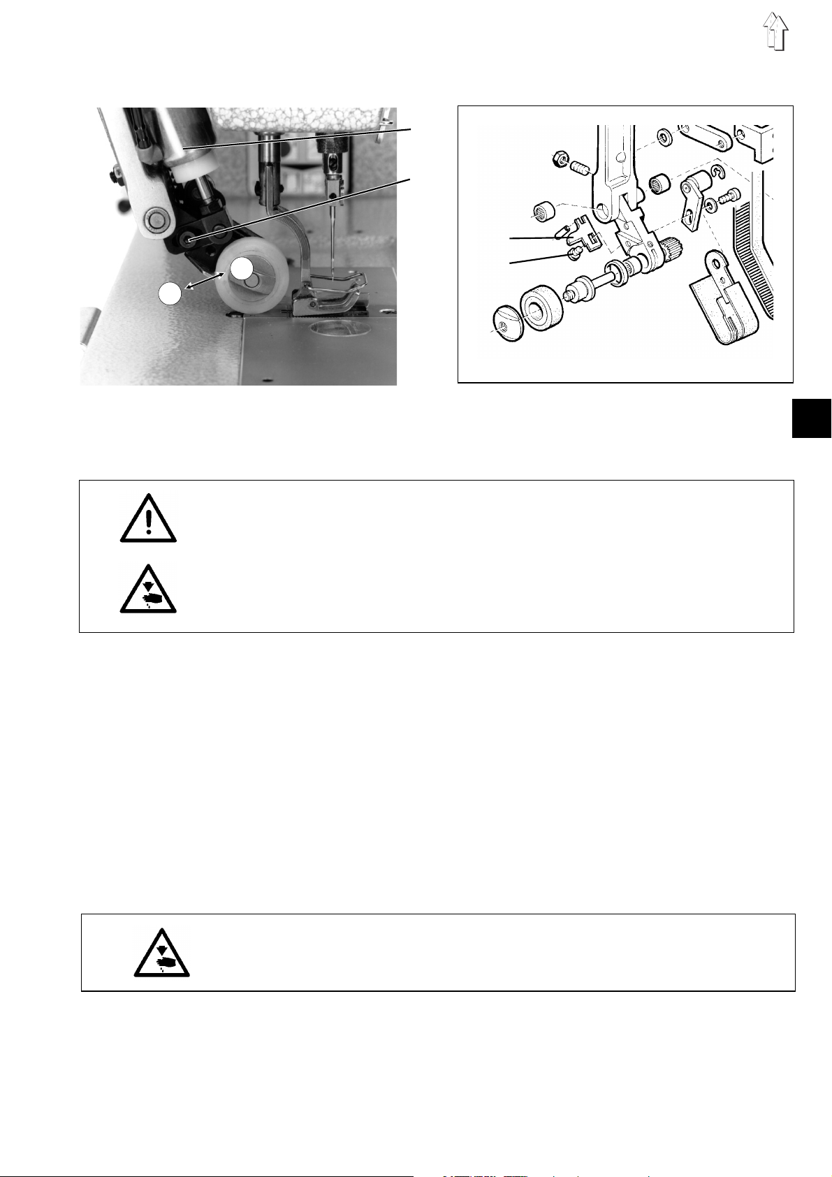
8.4 Puller pressure
Rule and control
The puller pressure must be adapted to the material involved.
NOTE !
After resetting the puller pressure proceed to a new adjustment of the
upper end position ! (see puller lifter lever)
Caution: Danger of bodily injuries !
Turn off main switch !
Turn off the sewing machine before correcting the puller pressure.
Correction
–
Looseen the screw 2.
–
Shift the cylinder 1.
In the A arrow direction = for reducing the pressure
In the B arrow direction = for increasing the pressure
–
Retighten the screw 2.
8.5 Fabric repeller
Rule and control
The purpose of the fabric repeller 3 is to avoid that the material enters
the gap. The fabric repeller should rest against the roller, but the latter
must still be able to move freely. Remove the fabric repeller when
using a steel puller !
Caution: Danger of bodily injuries !
Turn off main switch !
Turn off the sewing machine before correcting the fabric repeller.
Correction
–
Loosen the screw 4.
–
Adjust the fabric repeller 3.
–
Retighten the screw 4.
1
2
B
A
3
4
17
GB
Page 18

8.6 Toothed belt tension of the upper puller feed
23
1
Rule and control
The toothed belts should be tight enough to ensure an exact
transmission of the step length.
An excessive belt tension can result in an excessive wear and in
function disturbances.
Caution: Danger of bodily injuries !
Turn off main switch !
Turn off the sewing machine before correcting the belt tension above
and below.
Correctinf the toothed belt, above
–
Loosen the screw 2.
–
Shift the lever 3.
Adjust the tension of the toothed belt accordingly.
–
Retighten the screw 2.
Correcting the toothed belt, below
–
Loosen the screw 6.
–
Shift the lever 5.
Adjust the thension of the toothed belt 4 accordingly.
–
Retighten the screw 6.
456
18
Page 19

8.7 Replacing the puller
NOTE !
When a Vulkolan puller has been replaced by a steel puller or
viceversa proceed to a new adjustment of the lower end position !
(See chapter 8.3)
Remove the fabric repeller before using a steel puller !
When using the 15 mm wide rubbere puller, fit the wide fabric repeller
(ref. no..: 0273 000620 ).
Caution: Danger of bodily injuries !
Turn off main switch !
Turn off the sewing machine before replacing the puller.
Replacing the puller
–
Remove the nut 1.
NOTE Left handed thread !
Lock the axle 3 at the other end by a screwdriver.
–
Replace the puller 2.
–
Retighten the nut 1.
Pos. Ref. no..: Denomination
4 0933 005763 Steel puller 9 mm (1mm knurling)
5 0933 005737 Steel puller 15 mm (1 mm knurling)
6 0933 005738a Steel puller 15 mm, 2 mm saw-toothing
7 0933 005737a Rubber puller 15 mm
8 0933 005725 Rubber puller 9 mm
45 6 78
123
19
GB
Page 20

9. Needle bar height
1
0,1 mm
2
1,5 mm
3
4
Rule and control
In the loop stroke position, the hook tip 2 should stand in the middle of
the needle and 1.5 mm above the top of the needle eye.
–
Set stitch regulator on 0.
–
Lock the machine in position I.
–
Check the position of the hook tip in relation to the needle.
Correction
–
Turn out the screws 3.
–
Adjust the needle bar height by turning the needle holder 4 out and
in.
–
2
Set the needle holders so that their front faces are constituing one
flat surface.
–
Replace and retighten the screws 3.
12
0,1 mm
20
Page 21

10. Sewing foot height and sewing foot lift
The maximum sewing foot lift stroke amounts to 7 mm and in locked
position 4 mm.
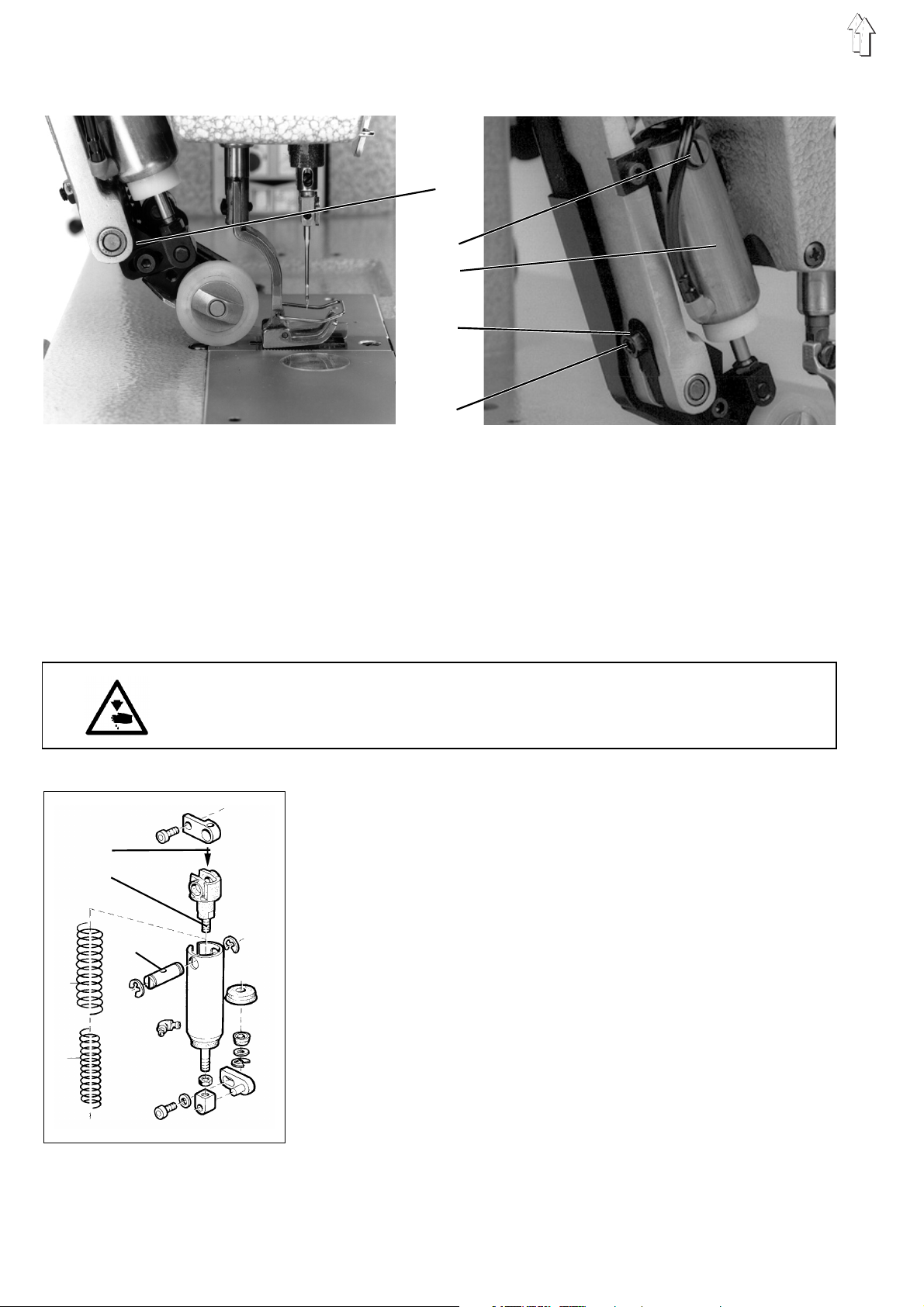
10.1 Height of the cloth presser bar
Rule and control
When the foot sole rests on the throat plate, the distance between the
cloth presser block 1 and the lifter lever 3 should range between 0,5
and1,0 mm.
Caution: Danger of bodily injuries !
Turn off main switch !
Turn off the sewing machine before correcting the the height of the
cloth pressere bar.
Correction
–
Remove the head cover.
–
Loosen the screw 2.
–
Set the distance between the block 1 and the lifter lever 3 to
0,5-1 mm.
–
Adjust the sewing foot so that the needle stitches in the middle of
the stitch hole in the sewing foot and retighten the screw 2.
–
Replace the head cover.
0,5-1 mm
1
2
3
4
21
GB
Page 22

10.2 Foot lift, mechanical
2
3
1
4
5
6
Rule and control
Set the levers 1 and 6 of the knee lever lift in such a way that at the
moment of lifting the free space under the sewing foot amounts to 7.0
mm. In the locked position, the free space must amount to 4.0 mm.
When the sewing foot rests on the throat plate, a slight dead travel in
the knee lever must be perceptible.
It should not impede the automatic sewwing foot lift.
With the sewing foot being lifted and with the needle bar being in its
lowest position, the needle block should not knock against the foot
sole.
Caution: Danger of bodily injuries !
Turn off main switch !
Turn off the sewing machine before correcting the knee lever.
Correction
–
Loosen the nut 5.
–
Set the maximum lift height by the stop screw 4.
–
Retighten the nut 5.
–
Loosen the nut 3.
–
Adjust the stop screw 2.
When the sewing foot rests on the throat plate, a slight dead travel
in the knee lever should be perceptible.
–
Retighten the nut 3.
22
Page 23

10.3 Foot lift, electropneumatic (autom. sewing foot lift)
Rule and control
Set the fork head of the lifter cylinder so as to attain the desired lift
stroke.
With the sewing foot being lifted and with the needle bar being in its
lowest position, the needle block should not interfere with the foot sole.
Caution: Danger of bodily injuries !
Turn off main switch !
Turn off the sewing machine before correcting the sewing foot lift.
Correction
–
Loosen the nut 2 and remove the bolt 3.
–
Adjust the fork head 1 of the cylinder. Turn the fork head out for
reducing the stroke and in for increasing the stroke.
–
Fit the bolt 3 and retighten the nut 2.
1
2
3
23
GB
Page 24

10.4 Sewing foot power
1
2
A B
Rule and control
With the sewing foot being lifted and with the needle bar being in its
lowest position, the needle block should not interfere with the foot sole.
Adjust the required sewing foot power by the knurled nut.
Correcting the sewing foot pressure
–
Set the sewing foot pressure by the knurled nut:
For increasing the sewing foot pressure = Turn the sleeve
clockwise.
For reducing the sewing foot pressure = Turn the sleeve counter
clockwise.
Correcting the setting sector
–
Remove the sleeve 1.
–
Remove the bolt 2, turn, and insert again.
Fit in position A = for higher sewing foot pressure
Fit in position B = for lower sewing foot pressure
–
Replace the sleeve 1 and set the desired sewing foot pressure by
the sleeve 1
NOTE!
For avoiding an involuntary resetting of the knurled nut, compress it in
the area of the safety slot.
24
Page 25

11. Thread guiding parts
11.1 Releasing the upper thread tension
Rule and control
In the basic position of the tension plate, the anchor 3 of the tension
releasing magnet 2 has a play of 0.3 mm in the axial direction. Check
by moving the nuts 4 and 5 in the axial direction.
Caution: Danger of bodily injuries !
Turn off main switch !
Turn off the sewing machine before correcting the upper thread
tension release.
Correction
–
Loosen the nuts 4 and 5.
–
Turn the nut 4 until its distance to the tension plate amounts to 0.3
mm and lock by the nut 5.
–
The anchor bar 3 on the back of the sewing machine arm can be
locked by a small screwdriver 1 (contained in the accessories).
–
Note: After a complete installation, the borehole is covered by the
cable. Displace the cable slightly sideways!
12 3 4 5
25
GB
Page 26

11.2 Thread tightening spring
12 3 4 5
Rule and control
The thread tightening spring 5 should keep the upper thread and the
tension at least until the point of the needle has reached the upper
side of the fabric.
If the upper thread is at this moment already slack, the descending
needle may stitch into its own upper thread.
The travel and the power of the thread tightening spring 5 can be
adjusted according to the thread and the fabric involved.
–
Turn the hand wheel slowly forwards and watch the thread
tightening spring while the needle stitches.
Caution: Danger of bodily injuries !
Turn off main switch !
Turn off the sewing machine before correcting the thread tightening
spring.
Correcting the spring power
–
Turn the thread tension axle 4.
–
Turn the axle clockwise for less power and counter clockwise for
more power.
Depending on the fabric and thread involved, the power of the
thread tightening spring should range between 50 and 70 cN.
–
It is advisible to remove the arm cover and to loosen the screw 1
before proceeding to the adjustment.
Correcting the spring travel
–
Loosen the screw 3.
–
Turn the bush 2. Turn counter clockwise for increasing the travel
and clockwise for reducing the travel.
–
Retighten the screw 3.
26
Page 27

12. Bobbin winder
Rule and control
The bobbin winder will stop automatically as soon as the the thread is
about 0.3 mm undere the bobbin diameter.
Caution: Danger of bodily injuries !
Turn off main switch.
Turn off the sewing machine before correcting the bobbin winder.
Correction
1. Small changes of the filling amount
–
Adjust the bobbin winder flap by the screw 4.
2. Major changes of the filling amount
–
Remove the arm cover.
–
Loosen the screw 2.
–
Turn the tripping cam 1.
in the A arrow direction: for the lower filling amount
in the B arrow direction: for a higher filling amount
–
Retighten the screw 2.
–
Replace the arm cover.
Correctinf the thread tension
–
Set the bobbin thread tension by the knurled nut 5. Turn clockwise
for increasing the tension.
–
Ensure by the adjustment a regular winding result (accurate
winding on the bobbin).
Correcting the winding
–
The winding should have a cylindrical form (no cone upwards or
downwards).
–
The winding form can be modified by rectifying the shank 6 on the
thread guide. Bend until a more or less cylindrical form is attained.
B
A
12
34
5
6
27
GB
Page 28

13. Hook adjustments
13.1 Loop stroke and distance of the hook tip to the needle
12
3
0,1 mm
Rule and control
The loop stroke is the distance covered by the needle bar from the
12
0,1 mm
lower dead point up to the point where the hook tip coincides with the
middle of the needle.
The loop stroke amounts to 2,0 mm.
With the machine being locked in position I and with the stitch length
"0", the hook tip should coincide with the middle of the needle. For
determining the loop stroke position use the setting pin, contained in
the accessories. Introduce thed setting pin into the tracing hole and
turn the machine out of its lower dead point until the pin snaps into the
groove I of the arm shaft crank. This will be the proper loop stroke
position.
When the machine is locked in position I , the distance between the
hook tip 2 and the needle 1 should amount to 0,1 mm.
In the loop stroke position the needle should rest against the needle
guard sheet and should avoid a contact between the needle and the
hook tip..
28
Caution: Danger of bodily injuries !
Turn off main switch !
Turn off the sewing machine before correcting the loop stroke and the
distance of the hook tip to the needle.
Correction
–
Remove the sewing foot, the throat plate, the feed dog and the
bobbin case top.
–
Lock the sewing machine in position "I".
–
Lock the "0" stitch length by the stitch regulator.
–
Loosen both screws 4.
–
Remove the oil collector sheet.
–
Loosen the screws 3.
–
Turn the hooks until their tips 2 coincide with the middle of the
needle.
–
Retighten the screws 3.
4
–
Fit the sewing foot, the throat plate, the feed dog and the bobbin
case top.
–
Fasten the oil collector sheet by the screws 4.
Page 29

13.2 Bobbin case lifter
Caution: Danger of bodily injuries !
Turn off main switch !
Turn off the sewing machine before opening the bobbin case.
Rule and control
The movement of the bobbin case lifter in relation to the hook
movement is determined by the eccentreic on the hook shaft..
The lifter finger 3 should turn the bobbin case 2 contrary to the
direction of rotation of the hook at the moment when the upper thread
loop, to be guided across the bobbin case, passes along the nose 1.
Set the lifter finger so that the bobbin case turns up to the middle of
the nose recess.
Correction
–
Loosen the screw 4.
–
Set the lifter finger 3 so that the bobbin case moves up to the
middle of the throat plate recess. If the travel of the bobbin case
lifter is excessive, undesired noises will be produced.
–
Retighten the screw 4.
1 2 3 4
11
29
GB
Page 30

14. Thread cutter
5
1
43 2
The control cam 3 determines the movement of the thread cutter and
the moment of the knife movement. This permits to time the
movements of the stitch forming elements.
The thread cutter is switched on by electromagnetic means.
14.1 Adjusting the control cam
Rule and control
Set the control cam in the axial direction so that, with the tripping
sheet 1 resting against the stop 2, ,the roller bolt 5 can enter freely the
pitch-free area of the cam race. In the negative, reset the control cam
3 and the setting ring 4 in the axial direction. Finally, proceed to a new
adjustment of the control cam in the circumference direction according
to chapter 14.4. The setting ring 4, on the left of the control cam,
determines the axial position of the control cam.
30
Page 31

14.2 Adjusting the thread cutter magnet
Rule and control
In the neutral position of the magnet 1, the play between the nut 4 on
the anchor bar of the magnet and the lower plastic disk 3 should
range between 0,2 and 0,3 mm.
Correction
–
Loosen the screw 2.
–
Adjust the magnet.
–
Retighten the screws 2.
14.3 Adjusting the roller bolt
Rule and control
With the thread cutter being switched off, the disance between the
face of the roller bolt 6 and the outer diameter of the cam body 5
should range between 0,2 and 0,3 mm.
Correction
–
Loosen the screw 7.
–
Shift the roller bolt so that the distance between the outer diameter
of the control cam and the face of the roller bolt ranges between
0,2 and 0,3 mm.
–
Retighten the screw 7.
1
6
54 3
2
7
0,2-0,3 mm
6
5
31
GB
Page 32

14.4 Timing the knife movement
1
4
3
2
Rule and control
Lock the machine in position IV for seting the control cam.
Correction
–
Loosen the two hexagon screws of the control cam 2.
–
Loosen the third hexagon screw of the control cam, but leave it
under a slight pre-tension.
–
Lock the machine in position IV by the locking pin.
–
Move the roller bolt 4 into the cam race by pressing on the tripping
sheet.
–
In the engaged position, the tripping sheet will be pressed to the
left.
–
The roller bolt must snap into the cavity 3 of the control cam.
–
In this position, fasten the first hexagon screw of the control cam.
–
Engage the tripping sheet.
–
Tighten the two remaining hexagon screws of the control cam.
32
Page 33

14.5 Height of the hook shaped knife and lateral distance to the throat plate
Rule and control
The travelling hook shaped knife should pass along the outer edge of
the throat plate at a distance of 0,3 to 0,4 mm.
The distance between the bottom of the hook shaped knife and the top
of the recess of ther bobbin case nose should range between 0,2 and
0,3 mm.
It should be possible to move the hook shaped knife by means of the
lifter finger (gapt 0,1 to 0,2 mm) and at the same time there should be
a gap under the throat plate slide of at least 0.2 mm.
Caution: Danger of bodily injuries !
Turn off main switch.
Turn off the sewing machine before correcting the hook shaped knife.
Correction
–
Remove the sewing foot and the throat plate slide.
–
Loosen the screws of the setting rings 1.
–
Set the left and the right hook shaped knife 2 0,2-0,3 mm above
the reespective bobbin case holding nose.
–
Fasten the setting ring 1.
–
Loosen the screws 3.
–
Set the hook shaped knife 2 that it stands 0,3 - 0,4 mm from the
throat plate edge.
–
Retighten the screws 3.
–
Fit the sewing foot and the throat plate slide.
3
2
1
3
2
1
33
GB
Page 34

14.6 Position of the hook shaped knife in relation to the counter knife
12 3
Rule and control
When the swinging hook shaped knife has reached its point of
inversion, the rear edge of the hook shaped knife should be flush with
the cutting edge of the counbter knife.
NOTE!
Sluggishness due to an excessive pressure would increase the wear.
Correction: Hook shaped knife in end position
–
press then tripping sheet 3 with the roller bolt 2 into the cams.
–
Turn the hand wheel, until the hook shaped knife reaches its point
of inversion.
–
Loosen the clamping screws 1.
–
Set the hook shaped knife 4 flush with the cutting edge of the
counter knife 5.
–
Retighten the clamping screws 1.
NOTE!
Seam starting problems can arise if the upper thread is set too short.
45
34
Page 35

14.7 Cutting pressure
Rule and control
The knives should cut at the minimum possible pressure.
The head of the setting screw of the stationary knife should always
rest against the base plate.
Correcting the knife pressure
–
Loosen the screw 3.
–
Set the counter knife 2 against the hook shaped knife 4.
–
Tighten the screw 3.
–
Turn the hexagon screw 1 by the 5.5 wrench, contained in the
accessories, until the screw head is supported by the machine
plate. If necessary, increase the pressure of the two knives by a
further rotation.
–
Make a cutting test – cut the thread by hand.
NOTE!
Set the knife pressure not higher than required, in order to avoid an
excessive knife wear.
14.8 Adjusting the thread clamap position
Rule and control
The distance between the thread clamping sheet and the cutting edge
of the counter knife should amount to 1,0 mm.
The distance between the top of the thread clamping sheet and the
bottom of the hook shaped knife should amount to 0,3 mm.
The hook shaped knife should guide the lower thread safely into the
cone-shaped opening between the rest plate and the thread clamping
sheet.
If necessary, rectify slightly the rest plate.
Correction
–
Loosen the screws 1.
–
Set the distance of the thread clamping sheet 2 to 1,0 mm.
–
Tighten the screws 1.
1,0 mm
12
4
3
2 1 2 3
4
35
GB
Page 36

14.9 Thread clamp pressure
12 3
Rule and control
Set the pressure exerted by the thread clamping sheet against the rest
sheet so as to ensure that the lower thread is safely caught and kept.
Correction
Reducing the clamping pressure
–
Bend the thread clamping sheet within the machine slightly
upwards.
Increasing the clamping power
–
Remove the screw 1.
–
Remove the rest sheet with the clamping sheet.
–
Remove the screw 2 and loosen slightly the screw 3.
–
Swing the clamping sheet.
–
Bend the clampaing sheet slightly downwards.
–
Return the clamping sheet to its initial position.
–
Retighten the screw 3.
–
Replace the screw 2.
–
Fasten the rest sheet and the clamping sheet by the screw 1.
Function test:
–
Press the lower thread end by the thumb against the base plate.
–
Move the hook shaped knife, containing the lower thread, into the
front end position and ensure that it is safely catched and clamped.
36
NOTE!
The clamping sheet sshould not exceed the edge of the rest plate
(see chapter. 14.8).
Page 37

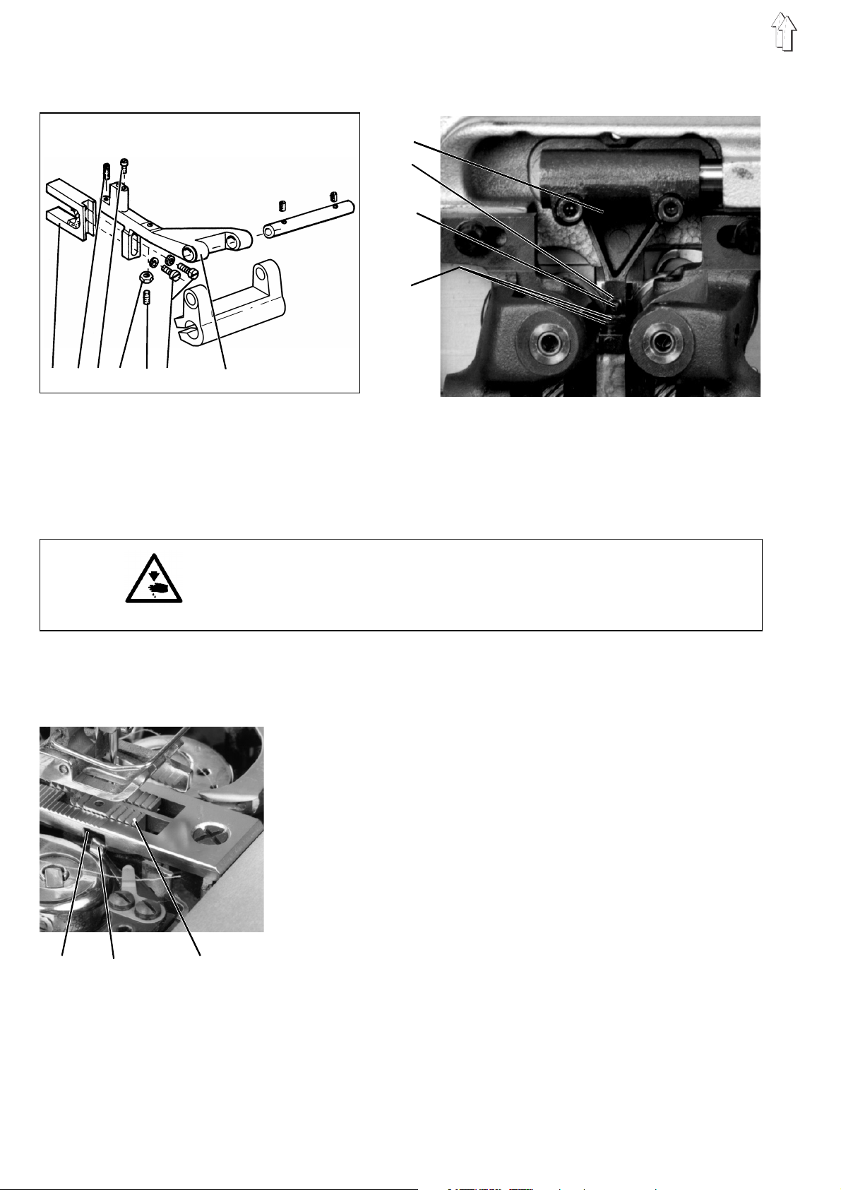
14.10 Transmission rods for the action of the hook shaped knife
Rule and control
When, following the engagement of the thread cutter, the rods are
moved through the cam body into the left outer position, the block 5
should be set to the left, so that it stands 3 mm from the oil collector
sheet. Set the block 2 parallel to the block 5.
Correction
–
For avoiding damages to the hook shaped knife, loosen the
clamping screws 1 and 6.
–
Lower the roller bolt 9 into the cam body.
–
Turn the hand wheel until the traction rod 8 stands in its outer
position.
–
Loosen the screws 7.
–
The block 5, being in its left end position, should stand 3 mm from
the oil collector sheet.
–
In both end positions, the rods 3 should be distanced 1 mm from
the oil collector sheet.
–
Retighten the screws 7.
–
Loosen the screw 4.
–
Set the block 2 parallel to the block 5.
–
Retighten the screw 4.
–
Adjust the position of the hook shaped knife in relation to the
counter knife according to chapter.14.6.
–
Retighten the clamping screws 1 and 6.
5678 9
1234
37
GB
Page 38

15. Needle bar crank and disconnectable needle bars
15.1 Removing the needle bar crank
7
6
5
1
4
8
3
2
Caution: Danger of bodily injuries!
Turn off the motor protective switch before removing the needle bar
crank!
–
Connect both needle bars.
–
Remove the sewing foot and the needles.
–
Removbe the head cover 4.
–
Remove the screw 7.
–
Remove the square 3.
–
Remove the wick 1 from the supporting sheet 8 and pull it out of
the sewing machine head.
–
Remove the wick 5 from the supporting sheet and pull it out of the
sewing machine arm.
Both wicks should remain unchanged on the needle bar crank!
–
Remove the cover plate from the sewing machine head.
–
Pull out the entire crank 2, and finally the bearing bolt 6.
38
Page 39

15.2 Removing a needle bar from the crank
–
Turn out the screws 6 and 8.
–
Remove he guide rail.
–
Set the tripping block 1 by the uncoupling bar 13 and push the
cross head 5 in the upper position so that it can be heard when
the three lowere balls 9 are jumping out.
–
Lower the cross head 5 down to the half of the needle bar stroke.
–
Turn out the safety screw 4 of the clamping ring 2 and the lower
festening screw.
–
Knock slightly by a soft object, e.g. by the screwdriver shaft,
against the threaded hole of the clamping ring 2 until the copper
pressure piece 3 gets off the needle bar.
–
Ensure that the pressure piece does not fall out and does not get
lost.
–
Remove the two safety halves 12. They are located in the ring
groove 11 and will be visible after lowering the clamping ring 2.
–
Displace the tripping block so that the two uncoupling bars 13 are
not operated.
–
Shift the cross head 5 on the needle bar slowly upwards until the
three upper coupling balls 10 jump out.
–
Ensure that the balls are not lost. They are under spring pressure.
–
Remove the needle bar from the crank 14 by pulling it down.
–
Ensure that the lower three balls 9 do not fall out of the ball holes
in he needle bar.
1
2
3
4
5
6
7
8
10 9
13
12
11
14
39
GB
Page 40

15.3 Stripping a needle bar
2
1
–
Remove the crank 19 and the needle bar as described above.
–
Turn out the screw 2 and remove the needle holder.
–
Note that the spring counter bearing stands under spring pressure.
–
Remove the parts contained in the needle bar from below.
15.4 Assembling a needle bar
–
–
–
3
–
–
4
–
5
–
6
7
–
–
19
8
9
Turn the plug screw 3 into the needle bar.
Pre-assemble the loweer coupling bar 17 in the illustrated
sequence.
Tighten the nut 9 to such a degree and secure the nut 8 so that the
distance between the bottom of the taper sleeve 11 and the top of
the domed cap nut 8 amounts to 30,5 mm.
Ensure this value and the length of the spring 10, specified in the
table, in order to attain the necessary coupling power, required for
the formation of stitches.
Slip the spring 5 and the sleeve 6 onto the thinner shaft end of the
uncoupling bar 4.
Introduce the uncoupling bar 4 with the thicker shaft end from
below into the needle bar 18 until it gets out of the plug screw 3.
Insert the conical bolt 7, with the cylindrical part up, into the
pre-assembled coupling bar 17, and introduce the spring 13 with
the spring 14 as well as the spring counter bearing 16 into the
needle bar.
Fasten the spring counter bearing 16 by the screw 15.
Lower the uncoupling bar 4 repeatedly and check whether the rods
are moving in the needle bar easily and in a springy way.
40
18
17
10
11
12
13
14
15
16
Page 41

15.5 Fitting the needle bars into the needle bar crank
–
Introduce the needle bar 7 from below into the crank 10.
–
Introduce the needle bar in the cross head 14 and the clamping
ring 13. The thin wall of the clamping ring must show up to the
other needle bar and to its cavity.
–
First push up the needle bar only so far that the three lowerball
holes 3are still under the crank.
–
Insert the balls 4 into the lower ball holes 3. Use grease in order to
ensure that the balls do not fall out!
–
Push the needle bar up until the lower balls disappear and the
upper ball holes 5 are visible.
–
Insert the three balls 6 into the upper ball holes 5.
–
Set the tripping block 1 above the uncoupling bar 2 of the needle
bar to be fitted.
–
Press needle bar upwards so as to actuate the uncoupling rod 2.
–
At the same time, lower the cross head 14 half distance, by pulling
it over the above balls 6.
–
Do not displace anymore the needle bar and the cross head,
because the balls, standing under spring pressure, might jump out.
–
Lower the clamping ring 13 on the needle bar until the ring
groove 9 is free.
–
Insert the two safety halves 8 into the ring groove. Push up the
clamping ring 13 up to the stop, so that the safety halves are
located in the cavity.
–
Press the cross head 14 upwards, against the clamping ring 13, up
to the stop. In this way, the needle bar will be linked with the cross
head.
–
Screw in the needle holder 11 and secure by the screw 12.
–
Turn the needle bar so that the front faces of the two needle
holders are constituing one flat surface.
1
2
10
9
8
7
6
5
4
3
13
14
12
11
41
GB
Page 42

13
15
16
16
17
14
18 19
–
Note: Set the precise needle height in relation to the hook after
fitting the crank according to the chapter "Needle bar height".
–
Fasten the clamping ring 13 on the needle bar and, before
tightening the fastening screw, ensure that the copper wire 15
rests with its inner radius properly against the needle bar;
ensure also that the two clamping rings 13 are well guided with
their round shoulders in he fork 17, fastened in the cross head
After tightening the fastening screw 16 tighten also the safety
screw 17.
–
6
Fasten the guide rail 19 by the screw, in order to avoid a distorsion
of the disconnected needle bar.
–
NOTE! The safety device 18 avoids after removing the needle bar
crank and disconnecting a needle bar that the cross
head 14 is lowered excessively, so that the upper balls 6
might jump out.
42
Page 43

15.6 Fitting the needle bar crank
–
Introduce the needle bar crank with the bearing bolt 2 into the arm
so that the hook ring 1 lies play-free in the cavity of the arm.
–
Tighten the screw 3.
–
Replace the square 7.
Fit the square so that the guides of the needle bar crank 5 have a
close fit.
Ensure that the needle bar crank is not jammed.
–
Clamp the wick 6 in the supporting sheet 8 and pass under the oil
felt 9.
–
Clamp the wick 4 in the supporting sheet 8 and pass under the oil
felt 10.
–
Replace the head cover.
–
Fit the sewing foot and the needle.
–
Fit the covering sheet.
–
Fit the threads guide.
–
Adjust the eccentric.
12 3
8
7
6
5
4
M A X
M I N
M A X
M I N
910
43
GB
Page 44

16. Changing the sewing equipment
1
9
6
8
23 4
5
6
7
10 11
13
12
–
Remove the needles.
–
Remove the screw 12.
–
Remove the needle heads 13.
–
Remove the sewing foot.
–
Remove the screw 11 and loosen the clamnping screw 10.
–
Remove the throat plate.
–
Turn out the screw 1 and remove the feed dog.
–
Inseert new needle heads and new needles (modified needle
distance.
–
Adjust the needle bar height according to chapter. 9.
–
Remove the oil collector tray 8.
–
Loosen the clamping screws 9 and the screw 6.
–
Loosen the clamping screws 3 and 4 and the toothed wheel 2
NOTE! The first screw, seen in the direction of rotation, will remain
in the shaft groove!
–
Shift the hook blocks in the axial direction. Ensure that the latereal
distance between the groove of the needle and the hook top
amounts to 0,1 mm , as specified in chapter. 9.
–
Tighten the clamping screws for the hook blocks 6 and 9.
–
Set the toothed wheel 2 at a distance of 0,2 mm from the holder
and tighten the screws 3 and 4 of the toothed wheel 2.
–
Adjust the loop stroke according to chapter. 13.1.
–
Fit new sewing foot, throat plate and feed dog. Note for the feed
dog the chapter. 5.
–
Replace the oil collector tray 8.
–
It is absolutely necessary to note the position of the hook shaped
knife in relation to the counter knife. See chjapter 14.5 ff.
–
Function test (turn the machine by hand).
–
Conduct a sewing test.
44
Page 45

17. Changing the toothed belt
Rule and control
For removing the toothed belt, remove the positioner, the hand wheel
and the rear arm shaft bearing through the arm hole.
Correction
–
Remove the head cover.
–
Remove the needles.
–
Remove the bobbin winder cover.
–
Turn the hand wheel and, by means of a long screwdriver, remove
the toothed belt from ist upper pulley by preswsisng it down and to
the left. The compensating weight of the driving eccenter will
stand in the lower position (see the sketch).
–
Remove the positioner, the hand wheel, the V-belt cover, the V-belt
and the hand wheel flange (incl. the ball bearing).
–
Remove the toothed belt through the upper housing hole.
–
Instrall the new toothed belt in the same way.
–
Replace the hand wheel. The first fastening screw 2, seen in the
direction of rotation, should stand on the flat surface of the shaft.
Fit the second screw.
–
The flat surface of the lower shaft 2 is vertical at the front (see the
sketch).
–
Place the new toothed belt first on he lower pulley.
–
Note the position of the eccentreic 1 (see the sketch).
–
Place the toothed belt on the upper pulley.
–
By turning the upper shaft, the toothed belt will be centered on the
upper pulley.
–
Replace the V-belt, the V-belt cover, the hand wheel and he
positioner.
NOTE!
With the stitch length being "0" and withn the tracing position pre-
vailing, the hook tip – in the loop stroke position – should coincide
with the middle of the needle.
If the position is not attained, repeat the process and reset the toothed
belt accordingly.
Set the positioner according to the Opeerating Instructions.
1
2
45
GB
Page 46

18. Lubrication
Caution: Danger of bodily injuries !
Oil can cause skin rashes.
Avoid protracted contact with the skin.
Wash thoroughly after contact.
NOTE !
The handling and disposal of mineral oils are governed by legal
provisions.
Take used oil to an authorised acceptance point.
Protect the environment.
Take cdare not to spill any oil.
For replenishisng the oil supply containers, use exclusively the
ESSO SP-NK 10 oil or an equivalent quality oil with the following
specification:
–
Viscosity at 40° C : 10 mm
–
Flashspoint: 150 °C
ESSO SP-NK 10 oil can be obtained from dürkopp adler ag outlets
under the following reference numbers
2-litre cointainer: 9047 000013
5 litre container: 9047 000014
Lubrication of the machine head
–
Replenish the supply container 1 up to the mark "max." .
2
/s
1
46
Lubrication of wicks and felt parts
–
After long standstill periods lubricate slightly the wicks and the felt
parts.
Page 47

18.1 Oil circulation
The oil passes from the supply container 2 to the felt 1 in the sewing
machine arm. This ensures the lubrication of the lubrication points in
the arm and head area.
The oil projected by the crank passes via the wick 3 to the central
distribution tube 5, for ensuring the lubrication of the parts under the
base plate. The excessive oil is returned via the felt to the oil collector
tray 4. This point ensures the lubrication of the hook driving wheels, of
the hook shafts and of the case lifter.
This system ensures an effective lubrication and a reduced oil
consumption.
Caution: Danger of bodily injuries !
Turn off main switch.
Turn off the sewing machine before proceeding to any work on the oil
circulation system.
NOTE !
Following any mounting work, reconnect properly the hose ends and
the wicks.
M A X
M I N
M A X
M I N
1
2
3
5
4
47
GB
Page 48

18.2 Hook-drive lubrication
1
2
3
Classes 381 and 382 are equipped with oil free hooks.
Normally they are not to be oiled.
But when processing heavy-shedding materials, it could be useful to
oil the hook race occasionally.
–
When required, give some drops of oil to oiling points 1 and 2.
–
Check weekly whether the felt 3 under the hook drives is
sufficiently lubricated.
If necessary, lubricate the felt 3 at the open rigth and left corner
when installing.
48
Page 49

19. Sewing motors
For the information about the sewing motors for the classes 381 and
382 see the chapter 4 in the Installation Instructions Cl. 381 - 382.
19.1 Sewing motor control unit DA82GA
For information about the the DA82GA sewing motor control unit see
chapter 7 in the Opereating Instructions Cl. 381 - 382 and chapter 6 in
the Installation Instructions 381 - 382.
19.2 Sewing motor control unit 6F82FA
For information about the 6F82FA sewing motor control unit see the
chapter 8 of the Operating Instructions Cl. 381 - 382 and the chapter 6
of the Installation Instructions 381 - 382.
19.3 Positioning
For information about the needle bar positioning see the chapter 6 of
the Installation Instructions Cl. 381 - 382.
19.4 Setting thre machine specifical parameters
For information about the setting of the machine specifical parameters
see the chapter 6.11 of the Installation Instructions Cl.381 - 382.
The table of the machine specifical parameters of the DA82GA control
unit is contained under the chapter 6.11.3 of the Installation
Instructions Cl. 381 - 382, and the parameter values are contained in
the parameter sheet 9800 130014 PB50 (in the accessories).
The table of the machine specifical parameters of the 6F82FA control
unit is contained under the chapter 6.11.6 of the Installation
Instructions Cl. 381 - 382, and the setting values are specified in the
parameter sheet 9800 120009 PB50 (in the accessories).
19.5 Masterreset
For information about the masterset see the chapter 6.12 of the
Instrallation Instructions Cl. 381 - 382.
19.6 Parameter list
The table of the machine specifical parameters of the DA82GA control
unit is contained under chapter 6.11.3 of the Installation Instructions
Cl. 381 - 382, and the setting values are specified in the parameter
sheet 9800 130014 PB50 (in the accessories).
The table of the machine specifical parameters of the 6F82FA control
unit is contained under chapter 6.11.6 of the Installation Insrtructions
Cl. 381 - 382, and the setting values are specified in the parameter
sheet 9800 120009 PB50 (in the accessories).
For the complete parameter list see the Operating Instructions EFKA
DA82GA or. EFKA 6F82FA, belonging to the scope of delivery of the
sewing motor.
49
GB
Page 50

20. Maintenance
Caution: Danger of bodily injuries !
Turn off main switch.
Turn off the sewing machine before proceeding to any maintenance
work.
The maintenance work to be carried by the sewing machine
opereators daily or weekly (cleaning, oiling) is described under part I
of the Operating Instructions. This work is described in the followwing
table oinly for the purpose of completeness.
The work to be carried out Service hours
8 40 160 500
Machine head
Remove sewing dust under the throat plate X
Remove sewing dust between the feed dog bridges X
(remove the throat plate)
Remove sewing dust under the bobbin brake spring X
Control oil level omn the oil supply container X
Lubricate the hook several
times
Control toothed belt X
Dry clean needle heads, needle bars and the area X
of the needlde bar crank
Sewing motor
Remove sewing dust from the motor sieve X
Control V-belt state and tension X
Pneumatic System
Check water level in the pressure regulator X
Clean filters in the conditioning unit X
Check the system tightness X
NOTE !
The oil should be changed after the first 500 service hours
The oil is to be changed every 2 years irrespective of the service hours.
50
Page 51

21. Optional equipment
21.1 Thread wiper
Mounting and correction
–
Remove the puller housing (only in 382).
–
Fasten the housing with the control magnet on the back of the arm
by screws 1.
–
Remove bobbin winder cover.
–
Open the cover of the electro-distributor.
–
Push the cable lug of the wiper cable onto the contacts 11 and 12
of the electro-distributor.
–
Install the cable and the cable supporting spring (on the machine
back).
–
Install the cable in the cable duct of the bobbin winder cover.
–
Install the bobbin winder cover.
–
Remove the sewing foot fastening screw.
Nur bei 382:
–
Remove the head cover.
–
Loosen the clamping screw 15.
–
Turn the fabric bar 13 so that the head of the sewing foot fastening
screw shows to the front.
–
Fit the sewing foot, showing to the front.
–
Clamp the screw 15. Note the distance of 0.5 mm between the
block 12 and the lifter 14.
Bei 381 und 382:
–
Fasten the thread wiping mechanism 11 (381)or. 8 (382) by the
available longer sewing foot fasteneing screws (381: 10; 382: 5) to
the cloth presser bar.
–
Fasten the traction rod 7 by the screw 6 to the thread wiping
mechanism.
–
Loosen the clampaing screws 9.
–
Displace the electromagnets towards the housing so that , with the
stitches being set to their maximum value, the needle heads do not
knock against the wiper (rear end position).
11
10
9
1
8
7
3
6
5
2
3
4
1
381
382
15
14
13
12
51
GB
Page 52

381
1
382
11
2
10
9
3
1
8
4
7
3
6
5
In 382: In thisswiping position, the wiper wire rests slightly against the
sewing foot.
–
Tighten the screw 9.
–
Loosen the clamping screw 3.
–
Trace the machine in position IV.
–
Displace the wiper wire so that there is enough space under the
needles – about. 2 mm. Ensure that the swinging wiper wire does
not interfere with the finger guard.
–
Fit and adjust the belt guard, the hand wheel and the positioner.
–
Activate the thread wiper on the external control panel by the
parameter 14 or by the motor control unit.
–
In case of large needle distances, it is possible to install the
available wide wiper wire.
52
Page 53

Page 54

Page 55

 Loading...