

Page 1
User Instructions
A.D.J. Supply Europe B.V.
Junostraat 2
6468 EW Kerkrade
The Netherlands
www.americandj.eu
Rev. 3/16
Page 2

A.D.J. Supply Europe B.V. – www.americandj.eu – Stinger II Instruction Manual Page 2
©2015 ADJ Products, LLC all rights reserved. Information, specifications, diagrams, images, and instructions
herein are subject to change without notice. ADJ Products, LLC logo and identifying product names and
numbers herein are trademarks of ADJ Products, LLC. Copyright protection claimed includes all forms and
matters of copyrightable materials and information now allowed by statutory or judicial law or hereinafter
granted. Product names used in this document may be trademarks or registered trademarks of their respective
companies and are hereby acknowledged. All non-ADJ Products, LLC brands and product names are
trademarks or registered trademarks of their respective companies.
ADJ Products, LLC and all affiliated companies hereby disclaim any and all liabilities for property, equipment,
building, and electrical damages, injuries to any persons, and direct or indirect economic loss associated with
the use or reliance of any information contained within this document, and/or as a result of the improper,
unsafe, unsufficient and negligent assembly, installation, rigging, and operation of this product.
Page 3

A.D.J. Supply Europe B.V. – www.americandj.eu – Stinger II Instruction Manual Page 3
Contents
GENERAL INFORMATION ........................................................................................................................................................ 4
GENERAL INSTRUCTIONS ........................................................................................................................................................ 4
FEATURES ................................................................................................................................................................................ 4
HANDLING PRECAUTIONS ....................................................................................................................................................... 4
SAFETY PRECAUTIONS ............................................................................................................................................................ 5
LASER WARNINGS AND SAFETY .............................................................................................................................................. 5
SET UP ..................................................................................................................................................................................... 6
INSTALLATION ......................................................................................................................................................................... 8
LASER WARNING LABELS ........................................................................................................................................................ 8
SYSTEM MENU ........................................................................................................................................................................ 9
OPERATION ........................................................................................................................................................................... 11
MASTER-SLAVE SET UP ......................................................................................................................................................... 12
POWER CORD DAISY CHAIN .................................................................................................................................................. 12
EMERGENCY BLACKOUT ....................................................................................................................................................... 12
UC IR/AIRSTREAM CONTROL ................................................................................................................................................ 12
2 CHANNEL MODE ................................................................................................................................................................ 13
9 CHANNEL MODE ................................................................................................................................................................ 13
FUSE REPLACEMENT ............................................................................................................................................................. 14
CLEANING.............................................................................................................................................................................. 14
TROUBLE SHOOTING ............................................................................................................................................................. 14
SPECIFICATIONS .................................................................................................................................................................... 15
ROHS - A great Contribution to the Conservation of Environment ..................................................................................... 16
WEEE – Waste of Electrical and Electronic Equipment ........................................................................................................ 17
NOTES ................................................................................................................................................................................... 18
Page 4

A.D.J. Supply Europe B.V. – www.americandj.eu – Stinger II Instruction Manual Page 4
INOZIONE
GENERAL INFORMATION
Unpacking: Thank you for purchasing the Stinger II by ADJ Products, LLC. Every Stinger II has been
thoroughly tested and has been shipped in perfect operating condition. Carefully check the shipping carton for
damage that may have occurred during shipping. If the carton appears to be damaged, carefully inspect your
fixture for any damage and be sure all equipment necessary to operate the unit has arrived intact. In the event
damage has been found or parts are missing, please contact our toll free customer support number for further
instructions. Please do not return this unit to your dealer without contacting customer support first.
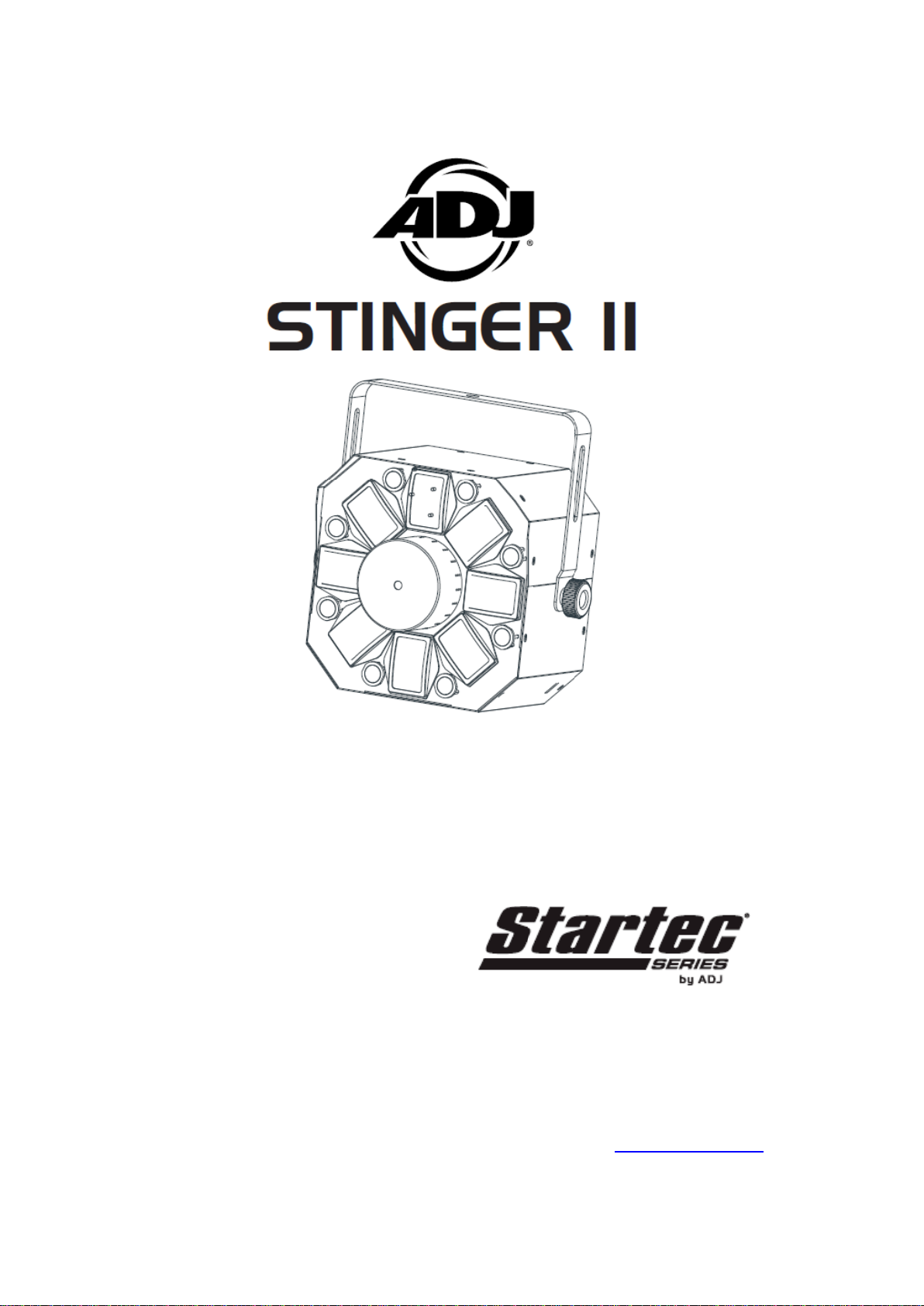
Introduction: The Stinger II is a DMX intelligent LED moonflower, strobe, & laser fixture. The Stinger II has 2
DMX channel modes, a 2 channel mode and 9 channel mode. The fixture can operate in as a stand alone
fixture or in a Master/Slave configuration. The Stinger II has three operating modes; sound active, show mode,
and DMX Control. For best results use fog or special effects smoke to enhance the beams projections.
Customer Support: If you encounter any problems, please contact your trusted American Audio shop.
We also offer the possibility, to contact us directly: You can contact us via our website www.americandj.eu or
via email: [email protected]
Warning! To prevent or reduce the risk of electrical shock or fire, do not expose this unit to rain or moisture.
Caution! This may cause eye damage. Avoid looking directly into the light source. Use sensible precaution.
GENERAL INSTRUCTIONS
To optimize the performance of this product, please read these operating instructions carefully to familiarize
yourself with the basic operations of this unit. These instructions contain important safety information regarding
the use and maintenance of this unit. Please keep this manual with the unit, for future reference.
FEATURES
• 2 DMX Channel Mode’s: 2 Channel and 9 Channel)
• 3 Operating Modes - Sound Active, Show Mode, & DMX Control
• RGBWAP Hex LED’s
• UV LED’s
• Green & Red Lasers
• Internal Microphone
• Digital Display for Address and Function Setting
• Power Cord Daisy Chain
• UC IR Compatiable (Not Included) & Airstream Compatiable
HANDLING PRECAUTIONS
Caution! There are no user serviceable parts inside this unit. Do not attempt any repairs yourself, doing so will
void your manufactures warranty. In the unlikely event your unit may require service please contact ADJ
Products, LLC.
During operation the housing may become extremely hot. Avoid touching the unit with bare hands while in use.
ADJ Products, LLC will not accept any liability for any resulting damages caused by the non-observance of this
manual or any unauthorized modification to this unit.
Page 5

A.D.J. Supply Europe B.V. – www.americandj.eu – Stinger II Instruction Manual Page 5
SAFETY PRECAUTIONS
Safety Issues: This unit may “pop” the fuse if the maximum allotted load of 2 amps is reached.
• To reduce the risk of electrical shock or fire, do not expose this unit rain or moisture.
• Do not spill water or other liquids into or on to your unit.
• Do not attempt to remove or break off the ground prong from the electrical cord. This prong is used to reduce
the risk of electrical shock and fire in case of an internal short. Do not attempt to operate this unit if the power
cord has been frayed or broken.
• Disconnect from main power before making any type of connection.
• Do not remove the cover under any conditions. There are no user serviceable parts inside.
• Always be sure to mount this unit in an area that will allow proper ventilation. Allow about 6” (15cm) between
this device and a wall.
• Do not attempt to operate this unit, if it becomes damaged.
• This unit is intended for indoor use only, use of this product outdoors voids all warranties.
• During long periods of non-use, disconnect the unit’s main power.
• Always mount this unit in safe and stable matter.
• Power cords should be routed so they are not likely to be walked on, pinched by items placed upon or
against them.
• Cleaning -The fixture should be cleaned only as recommended by the manufacturer. See page 14 for
cleaning details.
• Heat -The appliance should be situated away from heat sources such as radiators, heat registers, stoves, or
other appliances (including amplifiers) that produce heat.
• The fixture should be serviced by qualified service personnel when:
A. The power-supply cord or the plug has been damaged.
B. Objects have fallen, or liquid has been spilled into the unit.
C. The unit has been exposed to rain or water.
D. The unit does not appear to operate normally or exhibits a marked change in performance.
LASER WARNINGS AND SAFETY
NON-INTERLOCKED HOUSING WARNING
The Stinger II contains high power laser devices internally. Do not open the laser housing, due to the potential
exposure to unsafe levels of laser radiation. The laser power levels, if the unit is opened, can cause instant
blindness, skin burns and fires.
STOP AND READ ALL LASER SAFETY DATA
OPERATION INSTRUCTIONS AND LASER SAFETY
The light source emitted from this product can potentially cause eye injury if not set up and used properly. The
light source emitted from a laser is very different from any other light sources with which you may be aware of.
Laser light is thousands of times more concentrated than any light from any other kind of light source. This
concentration of light can cause instant eye injuries, primarily by burning the retina (the back of your eyeball
containing cells that are sensitive to light). Even if you cannot feel “heat” from a laser beam, it can still
potentially injure or blind you or your audience. Even very small amounts of laser beam light are potentially
hazardous even at long distances. Laser eye injuries can be sustained faster than you can blink.
Do not think that because this laser splits the laser beam into hundreds of beams and that the laser beam is
scanned out in high speed, that an individual laser beam is safe for eye exposure. This laser uses dozens of
Page 6

A.D.J. Supply Europe B.V. – www.americandj.eu – Stinger II Instruction Manual Page 6
LASER WARNINGS AND SAFETY (continued)
milliwatts of laser power (Class 3B levels internally) before it splits into multiple beams (Class 3R levels). Many
of the individual beams are potentially hazardous to the eyes.
Do not that because the laser light is moving, it is safe. This is not true. Nor, do the laser beams always move.
Since eye injuries can occur instantly, it is critical to prevent even the smallest possibility of any direct eye
exposure. In the laser safety regulation, it is not legal to aim Class 3R lasers in areas which people can get
exposed. This is true even if it is aimed below people’s faces, such as on a dance floor.
Do not operate the laser without first reading and understanding all safety and technical data in this
manual.
Always set up and install all laser effects so that all laser light is at least 3 meters (9.8 feet) above the floor on
which people can stand.
After setting up, and before public use, test laser to ensure proper function. Do not use if any defect is
detected. Do not use if laser emits only one or two laser beams rather than dozens/hundreds, as this could
indicate damage to the diffraction grating optic, and could allow emission of higher laser levels above Class
3R.
Do not point lasers at people or animals. Never look into the laser aperture or laser beams.
Do not point lasers in areas in which people can potentially get exposed, such as uncontrolled balconies, etc.
Do not point lasers at highly reflective surfaces, such as windows, mirrors and shiny metal. Even laser
reflections can be hazardous.
Never point a laser at aircraft, this is a federal offense.
Never point un-terminated laser beams into the sky.
Do not expose the output optic (aperture) to cleaning chemicals.
Do not use laser if the laser appears to be emitting only one or two beams.
Do not use the laser if the housing is damaged, the housing is open, or if the optics appear damaged in any
way.
Never open the laser housing. The high laser power levels inside of the protective housing can start fires, burn
skin and will cause instant eye injury.
Never leave this device running unattended.
The operation of a class 3R laser show is only allowed if the show is controlled by a skilled and well- trained
operator, familiar with the data included in this manual.
The legal requirements for using laser entertainment products vary from country to country. The user is
responsible for the legal requirements at the location/country of use.
Always use proper lighting safety cables when hanging lights and effects overhead.
SET UP
Power Supply: The ADJ Stinger II contains an automatic voltage switch, which will auto sense the voltage
when it is plugged into the power source. With this switch there is no need to worry about the correct power
voltage, this unit can be plugged in anywhere.
DMX-512: DMX is short for Digital Multiplex. This is a universal protocol used by most lighting and controller
manufactures as a form of communication between intelligent fixtures and controllers. A DMX controller sends
DMX data instructions from the controller to the fixture. DMX data is sent as serial data that travels from fixture
to fixture via the DATA “IN” and DATA “OUT” XLR terminals located on all DMX fixtures (most controllers only
have a DATA “OUT” terminal).
DMX Linking: DMX is a language allowing all makes and models of different manufactures to be linked
together and operate from a single controller, as long as all fixtures and the controller are DMX compliant. To
ensure proper DMX data transmission, when using several DMX fixtures try to use the shortest cable path
possible. The order in which fixtures are connected in a DMX line does not influence the DMX addressing. For
example; a fixture assigned a DMX address of 1 may be placed anywhere in a DMX line, at the beginning, at
the end, or anywhere in the middle. When a fixture is assigned a DMX address of 1, the DMX controller knows
to send DATA assigned to address 1 to that unit, no matter where it is located in the DMX chain.
Page 7
A.D.J. Supply Europe B.V. – www.americandj.eu – Stinger II Instruction Manual Page 7
SET UP (continued)
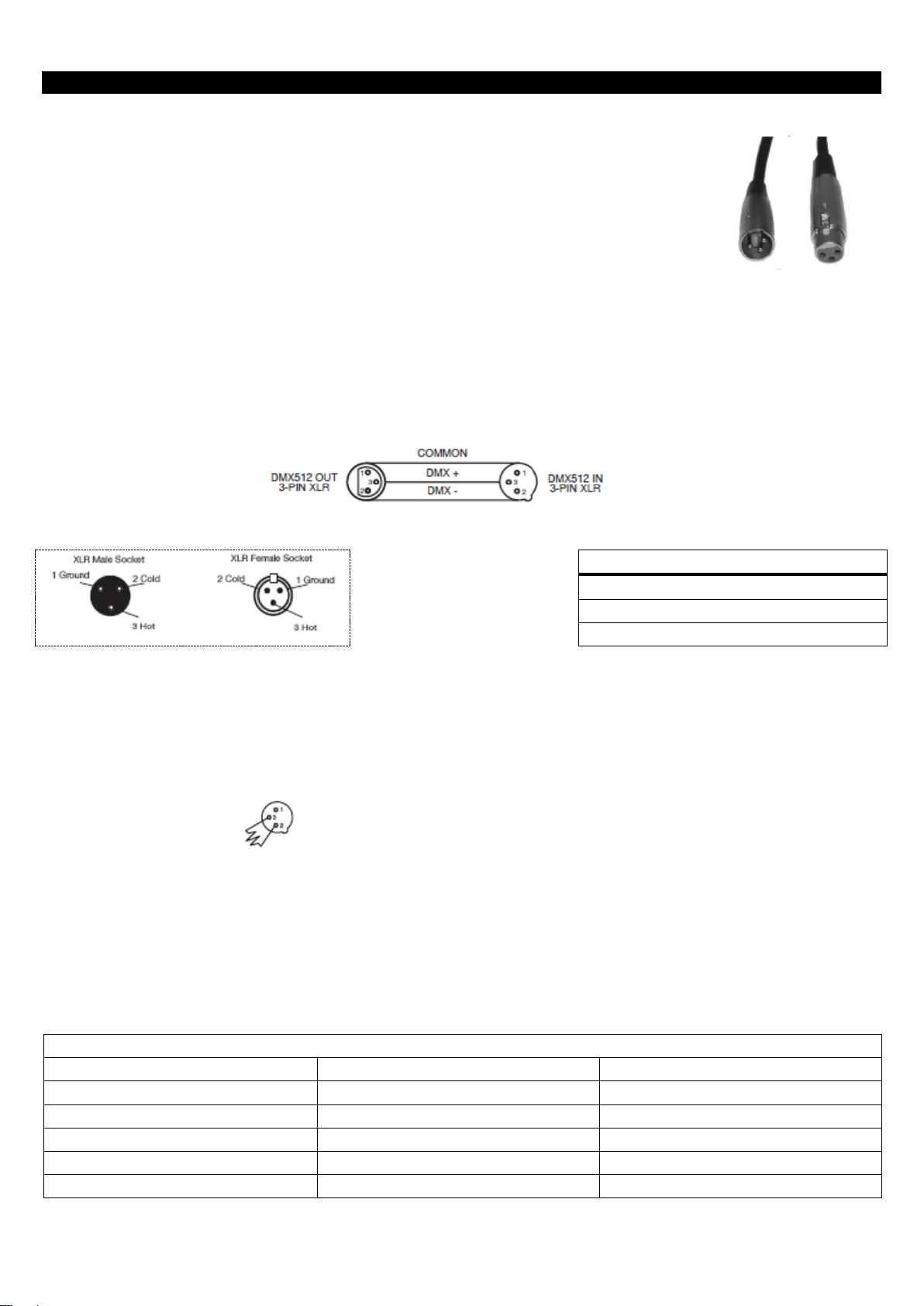
Data Cable (DMX Cable) Requirements (For DMX and Master/Slave Operation): The Stinger II can be
controlled via DMX-512 protocol. The Stinger II is has 2 DMX channel modes, a 2 channel mode and 9
channel mode. The DMX address is set electronically using the controls on the back
panel of the unit. Your unit and your DMX controller require a approved DMX-512 110
Ohm Data cable for data input and data output (Figure 1). We recommend Accu-Cable
DMX cables. If you are making your own cables, be sure to use standard 110-120 Ohm
shielded cable (This cable may be purchased at almost all professional sound and
lighting stores). Your cables should be made with a male and female XLR connector on
either end of the cable. Also remember that DMX cable must be daisy chained and
cannot be split.
Notice: Be sure to follow figures two and three when making your own cables. Do not use the ground lug on
the XLR connector. Do not connect the cable’s shield conductor to the ground lug or allow the shield conductor
to come in contact with the XLR’s outer casing. Grounding the shield could cause a short circuit and erratic
behaviour.
XLR Pin Configuration
Pin1 = Ground
Pin2 = Data Compliment (negative)
Pin3 = Data True (positive)
Figure 3
Special Note: Line Termination. When longer runs of cable are used, you may need to use a terminator on
the last unit to avoid erratic behaviour. A terminator is a 110-120 ohm 1/4 watt resistor which is connected
between pins 2 and 3 of a male XLR connector (DATA + and DATA -). This unit is inserted in the female XLR
connector of the last unit in your daisy chain to terminate the line. Using a cable terminator (ADJ part number
Z-DMX/T) will decrease the possibilities of erratic behaviour.
Termination reduces signal errors and avoids
signal transmission problems and interference.
It is always advisable to connect a DMX
terminal, (Resistance120 Ohm 1/4 W) between
PIN 2 (DMX-) and PIN 3 (DMX +) of the last
fixture.
Figure 4
5-Pin XLR DMX Connectors. Some manufactures use 5-pin XLR connectors for DATA transmission in place
of 3-pin. 5-pin XLR fixtures may be implemented in a 3-pin XLR DMX line. When inserting standard 5-pin XLR
connectors in to a 3-pin line a cable adaptor must be used, these adaptors are readily available at most
electric stores. The chart below details a proper cable conversion.
3-Pin XLR to 5-Pin XLR Conversion
Conductor
3-pin XLR Female (Out)
5-pin XLR Male (In)
Ground/Shield
Pin 1
Pin 1
Data compliment (- signal)
Pin 2
Pin 2
Data True (+ signal)
Pin 3
Pin 3
Not used Pin 4 - Do Not Use
Not used Pin 5 - Do Not Use
Figure 2
Figure 1
Page 8
A.D.J. Supply Europe B.V. – www.americandj.eu – Stinger II Instruction Manual Page 8
INSTALLATION
The unit should be mounted using a mounting clamp (not provided), affixing it to the mounting bracket that is
provided with the unit. Always ensure that the unit is firmly fixed to avoid vibration and slipping while operating.
Always ensure that the structure to which you are attaching the unit is secure and is able to support a weight
of 10 times the unit’s weight. Also, always use a safety cable that can hold 12 times the weight of the unit
when installing the fixture.
The equipment must be installed by a professional, and it must be installed in a place where it is out of the
reach of people’s grasp.
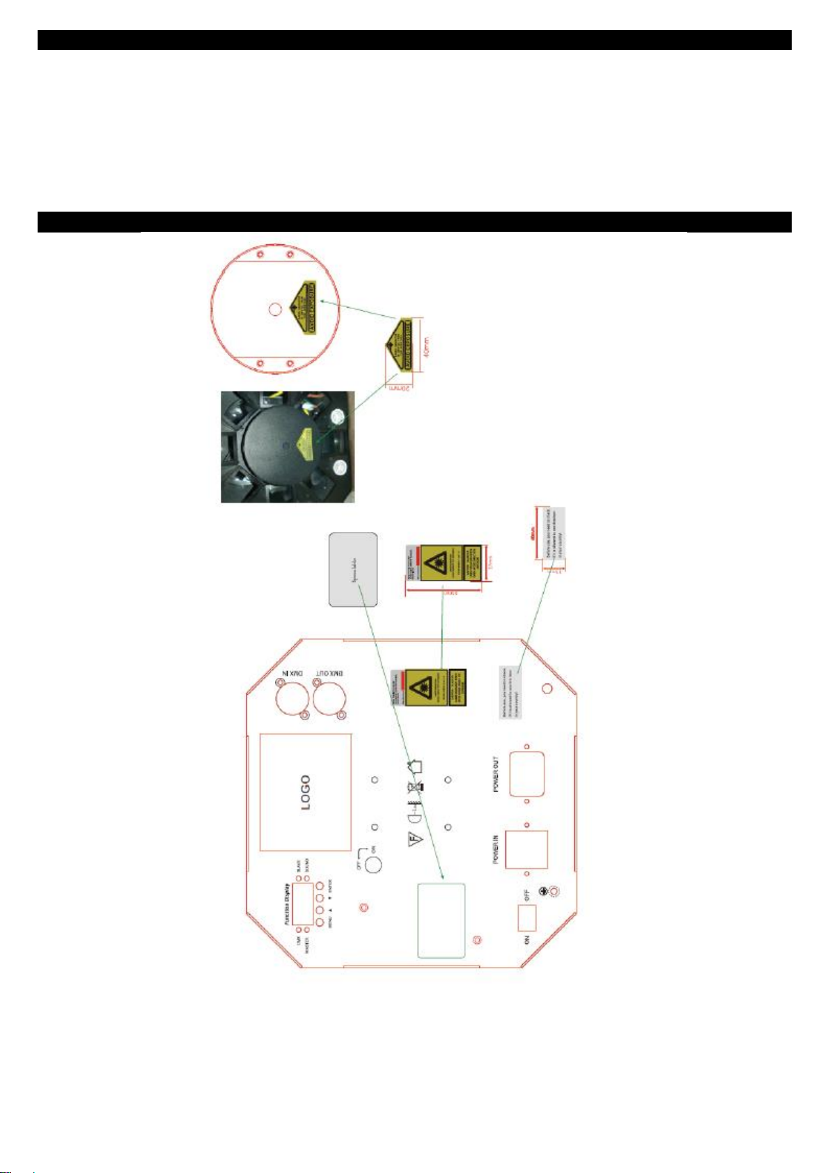
LASER WARNING LABELS
Page 9
A.D.J. Supply Europe B.V. – www.americandj.eu – Stinger II Instruction Manual Page 9
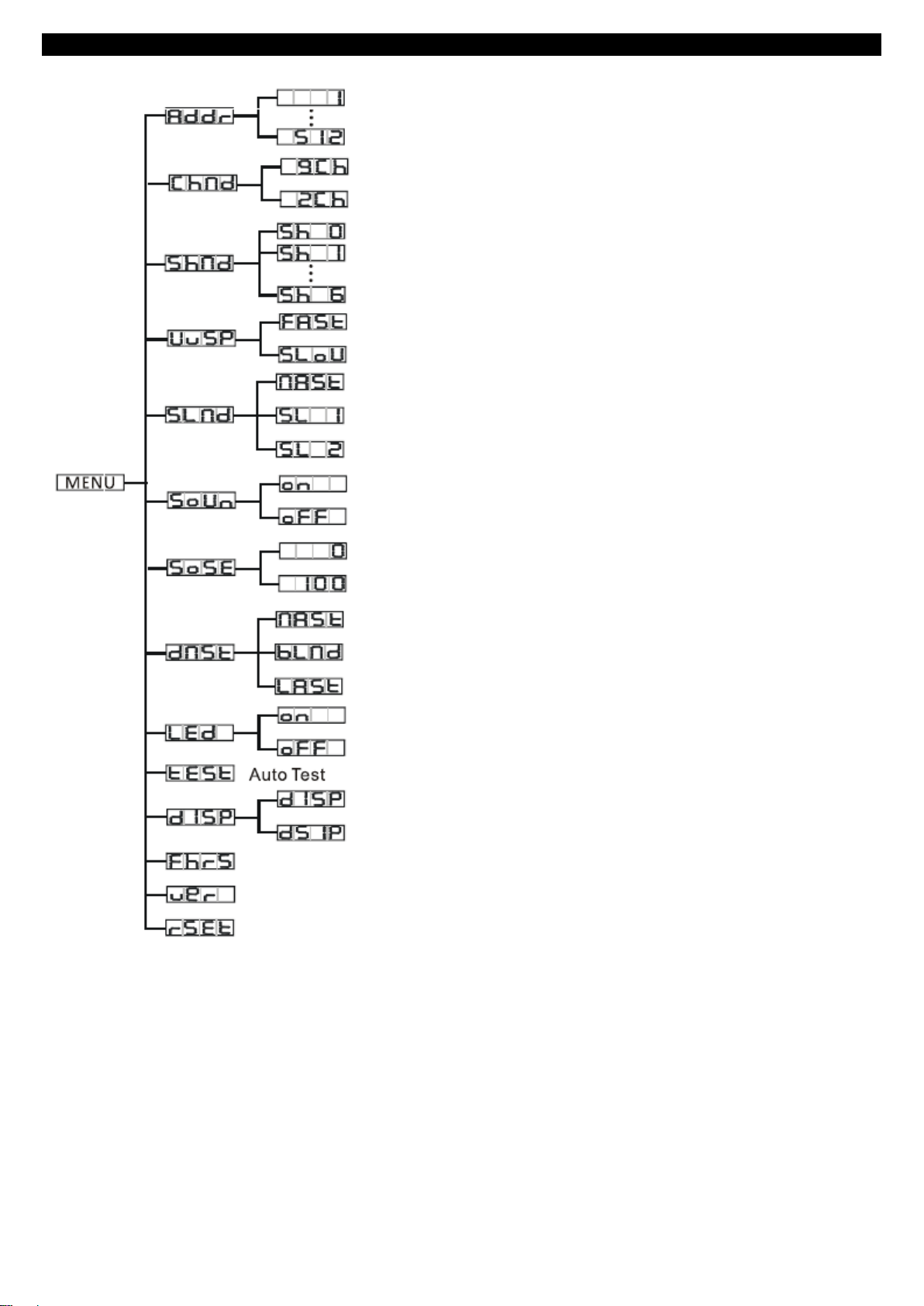
SYSTEM MENU
System Menu: When making adjustments press ENTER to confirm your setup then press and hold the
MENU button for at least 3 seconds. To exit without making any adjustments press the MENU button.
The display will lock after 30 seconds, press the MENU button for 3 seconds to unlock.
ADDR - DMX Address Setting.
1. Press the either the MENU, UP, or DOWN buttons until “ADDR” is displayed, press ENTER.
2. The current address will now be displayed and flashing. Press the UP or DOWN buttons to find your desired
address. Press ENTER to set your desired DMX address.
DMX Address
Channel Mode
Show Mode
UV speed
Slave Mode
Sound State
Sound Sense
Master State
Blackout Mode
Hold Last state
Led
Display Inversion
Auto Test
Fixture Hours
Software Version
Reset
Page 10

A.D.J. Supply Europe B.V. – www.americandj.eu – Stinger II Instruction Manual Page 10
SYSTEM MENU (continued)
CHND - This will let select your desired DMX channel mode.
1. Press the MENU button until “CHND” is displayed, press ENTER. The current DMX channel mode will be
displayed
2. Press the UP or DOWN buttons to find your desired DMX channel mode and press ENTER to confirm and
exit.
SHND - Show modes 0-7 (Factory programs).
1. Press the MENU button until “SHND” is displayed, press ENTER.
2. “Sh X” will now be displayed, “X” representing a number between 0-7. Shows 1-7 are factory programs,
while show “0” is random mode. Use the UP or DOWN buttons to find your desired show.
3. When you have found your desired show press ENTER, then press and hold the MENU button for at least 3
seconds to activate. After you have set your desired show, it can be changed at any time using the UP or
DOWN buttons.
UVSP - UV activation/speed control.
1. Press the MENU button until “UVSP” is displayed, press ENTER.
2. The display will show either “FAST” or “SLOW”. Use the UP and DOWN buttons to highlight your selection.
3. Press ENTER to confirm.
SLND - This will let you set unit as a master or slave in a master/slave configuration.
1. Press the MENU button until “SLND” is displayed, press ENTER. Either “MAST”, “SL 1”, or “SL 2” will be
displayed.
2. Press the UP or DOWN buttons until your desired setting is displayed, press ENTER to confirm.
Note: In a Master/Slave configuration you can set one fixture to Master and then set the next fixture to “SL 2”,
the fixtures will now have contrast movement to each other.
SOUN - Sound Active mode.
1. Press the MENU button until “SOUN” is displayed, press ENTER.
2. The display will show either “ON” or “OFF”. Press the UP or DOWN buttons to select “ON” to activate sound
active mode, or “OFF” to deactivate sound active mode.
3. Press ENTER to confirm.
SOSE - In this mode you can adjust the sound sensitivity.
1. Press the MENU button until “SOSE” is displayed, press ENTER.
2. A number between 0-100 will be displayed. Press the UP or DOWN buttons to adjust the sound sensitivity.
0 being the least sensitive, and 100 being the most sensitive.
3. When you have found your desired setting press ENTER to confirm.
DNST - This mode can be used as a precaution mode, that in case the DMX signal is lost,
interrupted, or power is lost, the operating mode chosen in the setup is the running mode the
fixture will go into when the DMX signal is lost. You can also set this as the operating mode you
would like the unit to return to when power is applied.
1. Press the MENU button until “DNST” is displayed, and either “MASL”, “BLND”, or “LAST” will be displayed
beneath.
2. Press ENTER and the bottom choice will begin to flash. Use the UP or DOWN buttons to choose an
operating mode you would like the unit to start up in when power is applied or the DMX signal is lost.
• LAST - If the DMX signal is lost the fixture will stay in the last DMX setting. If power is applied and this mode
is set, the unit will automatically go into the last DMX set up.
• MASL (Master Slave) - If the DMX signal is lost or power is applied, the unit will automatically go into Master
Slave mode and run a built-in show.
• BLND (Blackout) - If the DMX signal is lost or interrupted, the unit will automatically go into stand by mode.
3. Press ENTER to confirm your desired set up.
Page 11

A.D.J. Supply Europe B.V. – www.americandj.eu – Stinger II Instruction Manual Page 11
SYSTEM MENU (continued)
LED - With this function you can have the LED display turn off after 10 seconds.
1. Press the MENU button until “LED” is displayed, press ENTER.
2. The display will show either “ON” or “OFF”. Press the UP or DOWN buttons to select “ON” to keep the LED
display on at all times, or “OFF” to switch to have the LED display switch off after 10 seconds.
TEST - This function will run a self test program.
1. Press the MENU button until “TEST” is displayed, press ENTER.
2. The fixture will now run a self test.
DISP - This function will reverse the display 180º.
1. Press the MENU button until “DISP” is displayed, press ENTER.
2. Press ENTER to “flip” the display. Press ENTER to “flip” it again. Press ENTER when you have made your
desired setup.
3. Press ENTER to confirm. To make you LED display reappear again press any button.
FHRS - With this function you can display the running time of the unit.
1. Press the MENU button until “FHRS” is displayed, press ENTER.
2. The running time of the fixture will now be displayed. Press MENU to exit.
VER - Use this function to display the Software version of the unit.
1. Press the either the MENU button until “VER” is displayed, press ENTER.
2. The display will show the software version.
RSET - This function will reset the unit.
1. Press the MENU button until “RSET” is displayed. Press the ENTER button and the unit will reset itself.
OPERATION
Universal DMX Control: This function allows you to use a universal DMX-512 controller to control the
patterns, rotation and strobing. A DMX controller allows you to create unique programs tailored to your
individual needs.
1. The Stinger II is a 2 DMX channel channel modes; a 2 channel mode and 9 channel mode. See pages 1314 for detailed description of the DMX values and traits.
2. To control your fixture in DMX mode, follow the set-up procedures on pages 6-7 as well as the set-up
specifications that are included with your DMX controller.
3. Follow the instructions on page 9 to set the DMX address.
4. For longer cable runs (more than a 100 feet) use a terminator on the last fixture.
5. For help operating in DMX mode consult the manual included with your DMX controller.
Sound Active Mode: This mode allows a single unit or several units linked together, to run to the beat of the
music.
1. Press the MENU button until “Soun” is displayed, and press ENTER.
2. Press the UP or DOWN buttons to either activate sound active mode or deactivate, and press ENTER. The
unit will now run to the beat of the music.
3. The sound sensitivity can be adjusted by pressing the MENU button until “Sose” is displayed, and then
press ENTER. Use the UP or DOWN buttons to adjust the sound sensitivity, 0 being the least sensitive, and
99 being the most sensitive.
Show Mode: This mode allows a single unit or several units linked together, to run to a built-in program.
1. Press the MENU button until “Shnd” is displayed, and press ENTER.
2. Press the UP or DOWN buttons to find your desired show and press ENTER. The unit will now run your
chosen built-in program.
Page 12

A.D.J. Supply Europe B.V. – www.americandj.eu – Stinger II Instruction Manual Page 12
MASTER-SLAVE SET UP
Master-Slave Operation: This function will allow you to link up to 16 units together and operate without a
controller. In a Master-Slave set-up one unit will act as the controlling unit and the others will react to the
controlling units programs. Any unit can act as a Master or as a Slave.
1. Using approved DMX data cables, daisy chain your units together via the XLR connector on the rear of the
units. Remember the Male XLR connector is the input and the Female XLR connector is the output. The first
unit in the chain (master) will use the female XLR connector only - The last unit in the chain will use the male
XLR connector only. For longer cable runs we suggest a terminator at the last fixture.
2. On the Master unit press the MENU button until “SLND” is displayed, and press ENTER. Use the UP and
DOWN buttons to scroll to the “MAST” setting and press ENTER.
3. After setting the Master unit to the master setting find and set your desired operating mode.
4. On the slave units press the MENU button until “SLND” is displayed, and press ENTER. Choose either “SL
1” or “SL 2” and press ENTER. See page 10 for more info.
5. The slave units will now follow the Master unit.
POWER CORD DAISY CHAIN
With this feature you can connect the fixtures to one another using the IEC input and output sockets.
The quantity that can be connected is 10 fixtures maximum. After 10 fixtures you will need to use a
new power outlet. They must be the same fixtures. DO NOT mix fixtures
EMERGENCY BLACKOUT
This emergency feature lets you instantly blackout the unit. Have the emergency key inserted into the keyhole
at all times. To activate the emergency blackout feature turn it to the “Off” position. To reactivate the unit turn
the key to the “On” position.
UC IR/AIRSTREAM CONTROL
The UC IR (sold separately) infrared remote gives you control of various functions (See below). To control
the fixture you must aim the remote at the front of the fixture and be no more than 30 feet away.
The Stinger II comes with the Airstream IR remote transmitter. The ADJ Airstream IR is a universal infrared
remote control App used to control a variety of UC IR compatiable fixtures. You can download the Airstream IR
App in the iOS App store. The remote transmitter plugs into the headphone jack of your iOS phone or tablet.
The App comes with 3 pages of control depending on the IR fixture you are using. Please see your fixtures
user manual for the UC IR controls and corresponding App page. Additional Airstream IR transmitters are
available for purchase please contact your ADJ dealer.
Works with App page 1.
STAND BY - Pressing this button will blackout the fixture. Press the button again to return to the initial state.
FULL ON - Hold this button down to fully light up the unit. When you let the button go, the unit will return to its
previous state.
STROBE - Press and hold this button for strobing.
FADE/GOBO - This button is invalid for this fixture.
“DIMMER +” and “DIMMER -” - These buttons are invalid for this fixture.
COLOR - Press this button to activate color mode. Use buttons 1-9 to find your desired color.
1-9 - Use buttons 1-9 to select your desired color when color mode is active.
SOUND ON & OFF - Use the buttons to activate and deactivate sound active mode.
SHOW 0 - Press this button to activate show mode. Use buttons 1-6 to find your desired show.
Page 13
A.D.J. Supply Europe B.V. – www.americandj.eu – Stinger II Instruction Manual Page 13
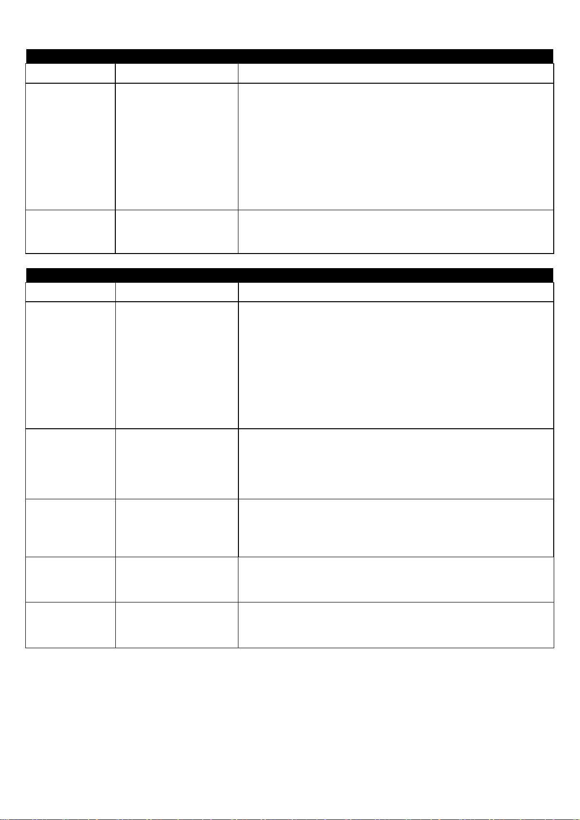
2 CHANNEL MODE
Channel
Value
Function
1
SHOW MODE
0 - 9
NO FUNCTION
10 - 44
SHOW 1
45 - 79
SHOW 2
80 - 114
SHOW 3
115 - 149
SHOW 4
150 - 184
SHOW 5
185 - 219
SHOW 6
220 - 255
RANDOM SHOW
2
SHOW SPEED/SOUND SENSE
0 - 247
SHOW SPEED SLOW - FAST
248 - 255
SOUND ACTIVE
9 CHANNEL MODE
Channel
Value
Function
1
SHOW MODE
0 - 9
NO FUNCTION
10 - 44
SHOW 1
45 - 79
SHOW 2
80 - 114
SHOW 3
115 - 149
SHOW 4
150 - 184
SHOW 5
185 - 219
SHOW 6
220 - 255
RANDOM SHOW
2
COLOR MACRO
0 - 9
NO FUNCTION
10 - 198
COLOR CHANGE
199 - 225
COLOR FADE 1
226 - 255
COLOR FADE 2
3
LED STROBE
0 - 9
NO STROBE
10 - 244
LED STROBE SLOW - FAST
245 - 255
SOUND ACTIVE STROBING
4
UV LEDS
0 - 134
BLACKOUT
135 - 255
UV CHASE
5
UV LED STROBE & CHASE SPEED
0 - 127
CHASE SLOW - FAST (NO STROBE)
128 - 255
CHASE SLOW - FAST (STROBING)
Page 14

A.D.J. Supply Europe B.V. – www.americandj.eu – Stinger II Instruction Manual Page 14
9 CHANNEL MODE (continued)
Channel
Value
Function
6
LASERS
0 - 9
BLACKOUT
10 - 49
RED LASER
50 - 89
GREEN LASER
90 - 129
RED & GREEN LASERS
130 - 169
RED & GREEN LASERS FLICKER
170 - 209
GREEN & RED LASERS FLICKER LASERS
210 - 249
RED & GREEN LASERS FLICKER SYNC
250 - 255
RED & GREEN LASERS ALTERNATE FLICKER
7
LASER STROBE CONTROL
0 - 9
NO STROBE
10 - 244
STROBING SLOW - FAST
245 - 255
SOUND ACTIVE STROBING
8
LED ROTATION
0 - 9
NO ROTATION
10 - 127
CLOCKWISE ROTATION SLOW - FAST
128 - 255
COUNTER-CLOCKWISE ROTATION SLOW - FAST
9
LASER ROTATION
0 - 127
LASER PATTERNS
128 - 255
PATTERN CHASE SLOW - FAST
FUSE REPLACEMENT
Disconnect the unit from its power source. Remove the power cord from the unit. Once the cord has been
removed, you will find that the fuse holder is located inside the power socket. Insert a flat-head screw driver
into the power socket and gently pry out the fuse holder. Remove the bad fuse and replace with a new one.
The fuse holder also has a holder for a spare fuse.
CLEANING
Fixture Cleaning: Due to fog residue, smoke, and dust cleaning the internal and external optical lenses and
mirror should be carried out periodically to optimize light output. Cleaning frequency depends on the
environment in which the fixture operates (I.e. smoke, fog residue, dust, dew). In heavy club use we
recommend cleaning on a monthly basis. Periodic cleaning will ensure longevity, and crisp output.
1. Use normal glass cleaner and a soft cloth to wipe down the outside casing.
2. Use a brush to wipe down the cooling vents and fan grill.
3. Clean the external optics and mirror with glass cleaner and a soft cloth every 20 days.
4. Clean the internal optics with glass cleaner and a soft cloth every 30-60 days.
5. Always be sure to dry all parts completely before plugging the unit back in.
TROUBLE SHOOTING
Trouble Shooting: Listed below are a few common problems that you may encounter, with solutions.
No light output from the unit;
1. Be sure the external fuse has not blown. The fuse is located on the rear panel of the unit.
2. Be sure the fuse holder is completely and properly seated.
Unit does not respond to sound;
1. Low frequencies (bass) should cause the unit to react to sound.
Tapping on the microphone, quiet or high pitched sounds may not activate the unit.
3. Check the sound sensitivity level.
Page 15

A.D.J. Supply Europe B.V. – www.americandj.eu – Stinger II Instruction Manual Page 15
SPECIFICATIONS
Model:
Stinger II
Voltage:
LED:
Laser:
Power Draw:
Fuse:
Power Cord Daisy Chain::
Dimensions:
Weight:
Colours:
Duty Cycle:
DMX Channels:
Sound Active
Working Position:
100V ~ 240V 50/60Hz
6 x 5W RGBAWP Hex LEDs
8 x 3W UV LEDs
4.9mW Red & Green Laser Diodes
70W
2A
10 Fixtures Max.
12”(L) x 9”(W) x 9.75”(H)
304mm x 230.5mm x9.75mm
11 lbs. / 5 kgs
RGBAWP
None
2 DMX Modes: 2 & 9 Channels
Yes
Any Safe, Secure Position
Auto Sensing Voltage: This fixture contains a automatic voltage switch, which will auto sense the voltage
when it is plugged into the power source.
Please Note: Specifications and improvements in the design of this unit and this manual are subject to change
without any prior written notice.
Page 16

A.D.J. Supply Europe B.V. – www.americandj.eu – Stinger II Instruction Manual Page 16
ROHS - A great Contribution to the Conservation of Environment
Dear Customer,
The European Union has adopted a directive on the restriction / prohibition of the use of hazardous
substances. This directive, referred to as ROHS, is a frequently discussed topic in the electronic industry.
It restricts, among other things, six materials: Lead (Pb), Mercury (Hg), hexavalent chromium (CR VI),
cadmium (Cd), polybrimated biphenyls as flame retardant (PBB), polybrominated diphenyl, also a flame
retardant (PBDE). The directive applies to nearly all electronic and electrical devices whose mode of operation
involves electric or electromagnetic fields – in short: each kind of electronics we have around us in our
households or at work.
As manufacturers of products of the brands of AMERICAN AUDIO, AMERICAN DJ, ELATION Professional
and ACCLAIM Lighting, we are obligated to comply with the RoHS directive. Therefore, as early as two years
prior to the directive coming into force, we started our search for alternative environmentally friendly materials
and manufacturing processes.
Well before the RoHS directive took effect, all of our products were manufactured meeting the standards of the
European Union. With regular audits and material tests we can still assure that the components we use are
always RoHS-compliant and that the manufacturing process, as far as the state of technology allows, is
environmentally friendly.
The ROHS directive is an important step to the protection of our environment. We, as manufactures, feel
obligated to make our contribution in this respect.
Page 17

A.D.J. Supply Europe B.V. – www.americandj.eu – Stinger II Instruction Manual Page 17
WEEE – Waste of Electrical and Electronic Equipment
Every year thousands of tonnes of electronic components, which are harmful to the environment, end up at the
waste disposals around the world. To ensure the best possible disposal or recovery of electronic components,
the European Union has adopted the WEEE directive.
The WEEE-system (Waste of Electrical and Electronic Equipment) can be compared with the system of the
“Green Spot”, which has been in use for several years. The manufactures have to make their contribution to
the utilization of waste at the time they release the product. Money resources obtained by doing so will be
applied to develop a common system of waste management. Thereby we can ensure professional and
environmentally friendly scraping and recycling program.
As manufactures, we are part of the German system of EAR and we make our contribution towards it.
(Registration in Germany: DE41027552)
That means that products of AMERICAN DJ and AMERICAN AUDIO can be left in the collection points free of
charge and they will be used in the recycling program. Products of ELATION Professional, which are used
only by professionals, shall be handled by us. Please send Elation products directly to us at the end of their
lifetime so that we can professionally dispose of them.
Like the above ROHS, the WEEE directive is an important contribution to the environment protection and we
are glad to help to clean the environment with this disposal system.
We are happy to answer any of your inquiries and welcome your suggestions at: [email protected]
Page 18

A.D.J. Supply Europe B.V. – www.americandj.eu – Stinger II Instruction Manual Page 18
NOTES
Page 19

A.D.J. Supply Europe B.V. – www.americandj.eu – Stinger II Instruction Manual Page 19
NOTES (continued)
Page 20

A.D.J. Supply Europe B.V. – www.americandj.eu – Stinger II Instruction Manual Page 20
A.D.J. Supply Europe B.V.
Junostraat 2
6468 EW Kerkrade
The Netherlands
www.americandj.eu
 Loading...