

yl
n z
c
a
r
m
d h
w
pv
c
z i
f a
n
u p
t
x
r h
Solutions for better hearing
e z t
l u
gc l
s q
y
u
d
i
r a di o
li g ht
d ir II
p
m h
k
v
RadioLight DIR II
Operation
Instructions


Contents
. Assembling the transmitter
. How it works
. Radio range
. Channel selector A, B, C
. Volume adjustment of the receiver
. Battery pack replace
. Maintenance of the headset receiver
. Replacing the silicone covers with the transparent
cover of the volume control
. Receiver: Trimmer adjustments Balance
. Please note the following informations
. Dealing with problems
. Disposal
. Warranty
. Technical data
1
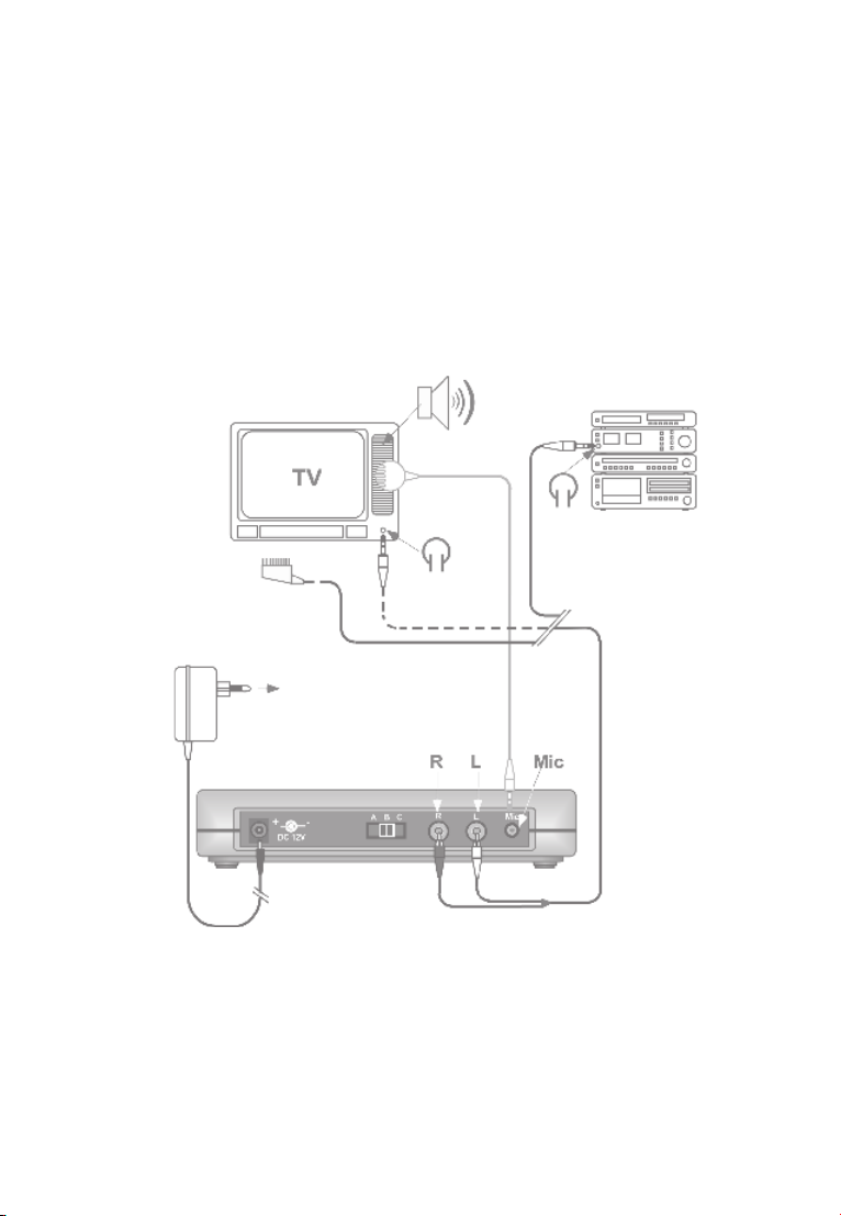
. Assembling the transmitter
HiFi
CD-Recorder
SCART
Power supply unit
DVD-Recorder
Walkman etc.
The volume adjustment of the TV, HIFI, CD should be set
to a comfortable listening level for other members of the
household.
2
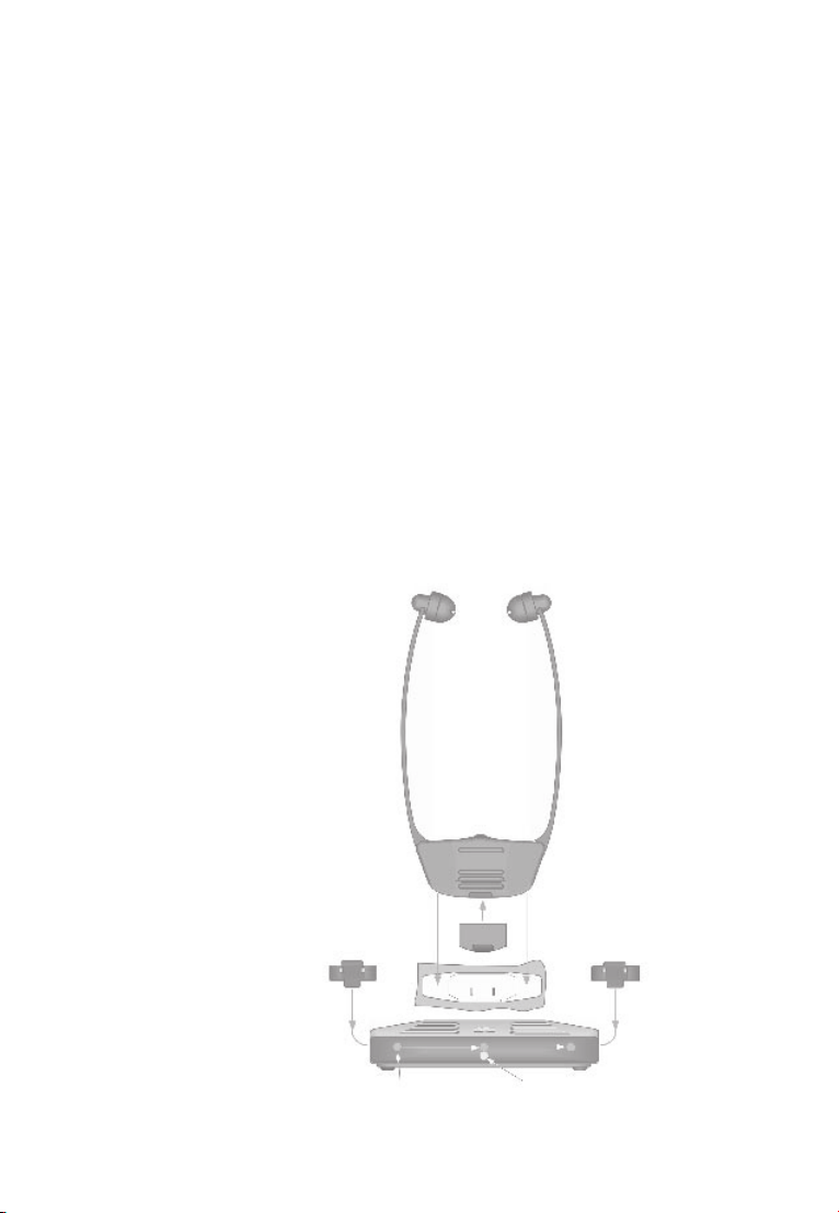
. How it works
When you first charge the batter y packs for the headset
receiver, charge them for at least 6 hours. Only use original
battery packs.
The package includes two battery packs and one dummy. You
will recognize the dummy as it has no metal contact surfaces.
Standby indicator:
The blue LED indicates that
the device has established
a connection with the
audio source and is on
Send.
Charging control light:
Red LED: Battery is in the
battery recharger and is in
the process of being
recharged
Green LED: Battery is fully
recharged
Charging
control light
Standb y
indicator
3

. Radio range
The transmitter is designed to have a radio signal range of
metres under optimum conditions.
The following conditions may result in a reduced range:
Signal transmission through building structures or
vegetation
Interference from TVs, computer monitors and mobile
phones. Under certain circumstances, this may prevent
the receiver from functioning at all.
Positioning of the transmitter at an unfavourable distance
from surfaces which reflect radio waves, for example floors
and walls. This may lead to the signal wave being weakened
or even cancelled out by the reflected wave.
Metallic objects reduce the range due to the shielding
eect of the metal.
Particularly in towns and cities, there may be many other
sources of radio waves which can disrupt the original signal.
Having units operating at similar frequencies located close
to one another may also result in mutual interference.
4
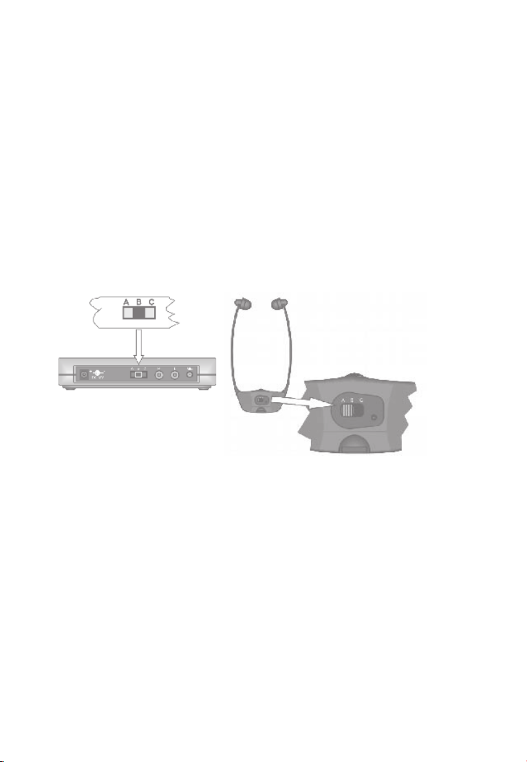
. Channel selector A, B, C
With the channel selector you can change the frequency of the
transmitter. If channel A is distorted you can change to another
channel.
NOTE: If the transmitter is switched to another channel, the
receiver also has to be set to another channel.
See specifications.
The channel selector is located on the rear side of the
transmitter or receiver.
Transmitter and receiver must both be set to the same channel.
5

. Volume adjustment of the
receiver
There is no ON/OFF switch!
The receiver automatically switches on when worn.
The stethoscope headset will switch o automatically when
you remove it.
Volume adjustment
6

. Battery pack replace
If the sound quality of the receiver becomes noisy and distorted
you should replace the battery pack with a charged one or
charge the receiver, including battery, in its cradle.
WARNING: Do not force the battery pack into the charger or
receiver!
How to get the most out of your rechargeable batteries
Please make sure that both batteries are used on a regular
basis. Constantly recharging the batteries will shorten their
service life. That’s why you should exchange the batteries
in the hearing aid with the batteries in the charging station
regularly (for best results, once a week).
7

. Maintenance of the headset
receiver
The ear pieces have to be cleaned or exchanged if dirty.
To replace, please use the silicone earpieces for DIR headsets.
8

. Replacing the silicone covers
with the transparent cover of the
volume control
The transparent cover has the following protective functions:
It prevents any unintentional changes in the volume level.
It protects dust and liquids from coming into contact with
the volume control.
Transparent cover for the
volume control
9

. Receiver:
Trimmer adjustments Balance
L=R L=R L=R
10
equal on left
and right
left dB right dB

. Please note the following
informations
If the system needs cleaning ONLY use a soft damp cloth.
If the ear pieces become damaged they should be replaced.
The product warranty does not cover normal wear or damage
resulting from misuse, neglect, improper storage, accident,
unauthorised repair or alteration.
Important Notice
This product is not protected against splash water. Do not
place any containers filled with water, such as flower vases, or
anything with an open flame, such as a lit candle, on or near
the product.
11

. Dealing with problems
Symptom
Recharging co ntrol lights.
Don’t light up whe n batteries
are placed into the batter y
compar tments proper ly.
Recharging co ntrol light does
not light up on th e same side
of the transmitter wh ere a
batter y is inserted.
The middl e recharger control
light does no t light up despite
having the receiver place d
into its com partment in the
transmitter.
Receiver d oesn’t work.
No audio signals being
received.
12
Cause
Transmitter n ot connected to
the power a dapter or no power
supply.
No contac t has been made
betwe en the battery and the
recharging contact s of the
compar tment of the trans mi tte r.
No contac t has been made
betwe en the battery in the
receive r and the recharging
contacts of the compartment
in the tra nsmitter.
There is no b attery inser ted
into the receiver.
The tra nsmitter is not corre ctly
connec ted to the TV or HI- FI
audio output.
Your TV or HI -FI equipment is
not turne d on.
Solution
Make sure that t he power
adaptor is connected to t he
mains powe r socket and to the
transmitter.
The batt ery has not bee n correctl y and completely ins erted
into the bat tery compar tment.
The rece iver has not been
proper ly placed into the
compar tment. Make sure it is
facing in the correct dire ction.
Insert a b attery into the
receiver.
Pleas e check and make sure
the audio con nection cable s
to the T V or HI-FI are properly and co rrectly conne cted.
Pleas e read through the
owner’s manual for your T V or
HI-FI equ ipment to make sure
if the out put for headphone or
line outpu t is connected and it
does wor k correctly.

Symptom
Cause
Solution
Receiver d oesn’t work.
No audio signals being
received.
The audio t ransmission is of
poor quali ty, noisy, distorted,
unclear or n o audio signals being receiv ed.
Batter y pack no longer give s
the exp ected operat ing time
per charge.
No batter y is inserted into the
receiver.
Batter y is discharged
You are too far away with your
receive r from the transmit ter.
If using a 100 Hz te levision
and the tr ansmitter is placed
on top of it the sound may
become dis tored in the recei ver
headset.
Batter y is discharged
Batter y pack is not fully
charged.
Batter y pack has reache d its
recharging limit.
Insert a b attery into the
receiver.
Replace bat tery with a fully
charged on e.
Make sure you ar e not located
too far away fr om your transmi tte r.
Move the tr ansmitter to a
position where the distortion
does not occur.
Replace bat tery with a fully
charged on e.
Recharge the batter y for the
correc t time.
Replace bat tery pack with a
new one.
13

. Disposal
Disposal of used electric and electronic units applicable in the
countries of the European Union and other European countries
with a separate collection system.
The symbol on the product or the packaging indicates that
this product is not to be handled as ordinary household waste
but has to be returned to a collecting point for the recycling
of electric and electronic units. You protect the environment
and health of your fellow men by the correct disposal of this
products.
Environment and health are endangered by a faulty disposal.
Material recycling helps to reduce the consumption of raw
material. You will receive further information on the recycling
of this product from your local community, your communal
disposal company or your local dealer.
14

. Warranty
This warranty covers the repair of the product and returning it
to you free of charge. It is essential that you send in the product
in its original packaging, so do not throw the packaging away.
The warranty does not apply to damage caused by incorrect
handling or attempts to repair the unit by people who are not
authorised to do so destruction of the seal on the unit.
Repairs under warranty are only carried out providing you have
filled in and returned the enclosed warranty card from the
d ea le r.
Always specify the product number in any event.
15

. Technical data
Modulation FM
Frequency Channel A: 915.25 MHz
Channel B: 915.75 MHz
Channel C: 916.75 MHz
Transmition power 1 mW
Frequency response 15–20,000 Hz
Distorsion <1%
Noise level typ. 60 dB
Battery charging time approx. 6 h
Headset receiver
Operating time per change approx. 4–5 h
Maximum volume SPL approx. 120 dBA
Weight approx. 59 g
Transmitter
Power consumption approx. 3.6 VA
Operating voltage 12 Volt DC
Supply voltage 100–240 V AC, 50/60 Hz
Weight approx. 200 g
16

Operating Determinations
Trade Name Model Number
RadioLight DIR II
FCC ID:U94RFS05DIR08
This device complies with Part 15 of the FCC Rules. Operation is subject
to the following two conditions: (1) this device may not cause harm ful
interference, and (2) this device must accept any interference received,
including interference that may cause undesired operation.
This device is a set consisting of a wireless transmitter and
wireless headphones for receiving UHF-signals.
Areas of use
This device is designed for private use and professional use, e.g.
on stage, in discotheques, theatres etc.
This product was designed for indoor use only.
This product complies with European Union norms. You can
obtain EC compliance declarations from your dealer, or directly
from the manufacturer of this product.
Technical specifications subject to change without notice.
17

Federal Communication Commission Interference Statement
This equipment has been tested and found to comply with the limits
for a Class B digital device, pursuant to Part 15 of the FCC Rules.
These limits are designed to provide reasonable protection against
harmful interference in a residential installation.
This equipment generates, uses and can radiate radio frequency energy
and, if not installed and used in accordance with the instructions, may
cause harmful interference to radio communications. However, there is
no guarantee that interference will not occur in a particular installation.
If this equipment does cause harmful interference to radio or television
reception, which can be determined by turning the equipment off and
on, the user is encouraged to try to correct the interference by one of
the following measures:
. Reorient or relocate the receiving antenna.
. Increase the separation between the equipment and receiver.
. Connect the equipment into an outlet on a circuit different from that
to which the receiver is connected.
. Consult the dealer or an experienced radio/TV technician for help.
FCC Caution: To assure continued compliance, any changes or
modifications not expressly approved by the party responsible for
compliance could void the user's authority to operate this equipment.
(Example - use only shielded interface cables when connecting to
computer or peripheral devices).
18

Hightech made in Germany
audifon USA Inc.
403 Chairman Ct., Suite 1
Debar y, Florida 3 2713
PO BOX 531700
USA
Phone +01-386 -668-8812
Fax +01-386-753-9564
Toll Free 800.776.0222
contact.usa@audifon.com
www.audifon.com
 Loading...