

Additel ADT875 Operating Manual

Additel 875 Series Dry Well Calibrator
————User’s Manual
Latest version at www.additel.com
[Version:1903V04]
Additel Corporation
I

STATEMENT
This user’s manual provides operating and safety instructions for the ADT875 Series Dry Well Calibrator. To ensure correct operation and safety, please
follow the instructions in this manual. Additel Corporation reserves the right to change the contents and other information contained in this manual
without notice. For the most up-to-date manual, please visit www.additel.com.
II

CONTENT
Welcome .............................................................................................................................................................................................................. 1
How to Contact Additel ......................................................................................................................................................................................... 1
Safety Information ................................................................................................................................................................................................ 2
1. Introduction ...................................................................................................................................................................................................... 4
1.1 Model Information ....................................................................................................................................................................................................... 4
1.2 Basic Structure ........................................................................................................................................................................................................... 5
1.3 Features ...................................................................................................................................................................................................................... 6
1.4 Environmental Conditions .......................................................................................................................................................................................... 7
1.5 Technical Specifications ............................................................................................................................................................................................ 8
1.6 Standard Equipment................................................................................................................................................................................................. 16
2. Operation ....................................................................................................................................................................................................... 17
2.1 Main Screen .............................................................................................................................................................................................................. 17
2.2 System Temperature Unit Setup ............................................................................................................................................................................. 19
2.3 Temperature Output ................................................................................................................................................................................................. 20
2.4 DUT Measurement (Only for ADT875PC) .............................................................................................................................................................. 22
2.4.1 DUT Settings ...................................................................................................................................................................................................... 22
III

2.4.2 Thermal Resistance (RTD) & NTC Measurement .......................................................................................................................................... 23
2.4.3 Thermal Couple (TC) Measurement ................................................................................................................................................................ 25
2.3.4 Current (mA) Measurement .............................................................................................................................................................................. 27
2.3.5 Voltage (V) Measurement ................................................................................................................................................................................. 28
2.3.6 Switch Test ......................................................................................................................................................................................................... 30
2.3.7 Transmitter Measurement (including HART transmitter) ............................................................................................................................... 32
3. System Setup ................................................................................................................................................................................................. 36
3.1 Communication ......................................................................................................................................................................................................... 36
3.1.1 Ethernet .............................................................................................................................................................................................................. 36
3.1.2 WLAN ................................................................................................................................................................................................................. 37
3.1.3 Bluetooth® ......................................................................................................................................................................................................... 38
3.1.4 ACloud Service .................................................................................................................................................................................................. 38
3.2 Sensor Library (Only for ADT875PC) ..................................................................................................................................................................... 39
3.2.1 General Management ....................................................................................................................................................................................... 39
3.2.2 Smart Sensor ..................................................................................................................................................................................................... 41
3.2.3 ITS-90 ................................................................................................................................................................................................................. 43
3.2.4 CVD .................................................................................................................................................................................................................... 43
3.2.5 RTD .................................................................................................................................................................................................................... 44
IV

3.2.6 NTC .................................................................................................................................................................................................................... 45
3.3 Power Grid Settings (Only for ADT875PC/875 - 350 & 660) ................................................................................................................................ 46
3.4 Password Protection ................................................................................................................................................................................................ 46
3.5 Services ..................................................................................................................................................................................................................... 47
3.5.1 Calibration .......................................................................................................................................................................................................... 47
3.5.2 Restore ............................................................................................................................................................................................................... 65
3.5.3 Updates .............................................................................................................................................................................................................. 65
3.6 Personalization ......................................................................................................................................................................................................... 66
3.6.1 Temperature Unit ............................................................................................................................................................................................... 66
3.6.2 Date and Time ................................................................................................................................................................................................... 66
3.6.3 Language ........................................................................................................................................................................................................... 66
3.6.4 Sound ................................................................................................................................................................................................................. 67
3.6.5 Contrast .............................................................................................................................................................................................................. 67
3.6.7 Screen Saver ..................................................................................................................................................................................................... 67
3.6.8 Display Mode ..................................................................................................................................................................................................... 67
3.7 Product Information .................................................................................................................................................................................................. 68
4 Task (Only for ADT875PC) ............................................................................................................................................................................. 69
4.1 Task Settings ............................................................................................................................................................................................................ 69
V

4.1.1 Stable Judgment Condition Setup ................................................................................................................................................................... 69
4.2 Device Center ........................................................................................................................................................................................................... 70
4.2.1 DUT Management ............................................................................................................................................................................................. 70
4.2.2 RTD .................................................................................................................................................................................................................... 72
4.2.3 TC ....................................................................................................................................................................................................................... 73
4.2.4 Thermistor .......................................................................................................................................................................................................... 74
4.2.5 Transmitter ......................................................................................................................................................................................................... 75
4.2.6 Switch ................................................................................................................................................................................................................. 76
4.2.7 Liquid-In-Glass and Surface Thermometers ................................................................................................................................................... 77
4.2.8 Temperature Controller ..................................................................................................................................................................................... 78
4.2.9 Bimetallic Thermometer, Filled System Thermometer, and Transformer Thermometer ............................................................................. 79
4.2.10 Digital Thermometer ........................................................................................................................................................................................ 80
4.2.11 Tolerance Setting of DUT ............................................................................................................................................................................... 81
4.3 Test Center ............................................................................................................................................................................................................... 83
4.3.1 Test Task Management .................................................................................................................................................................................... 83
4.3.2 Task Settings ..................................................................................................................................................................................................... 85
4.4 Task Performance .................................................................................................................................................................................................... 92
4.4.1 DUT and Test Setting Selection ....................................................................................................................................................................... 92
VI

4.4.2 Task Performance ............................................................................................................................................................................................. 92
4.5 End of Task ............................................................................................................................................................................................................... 98
4.5.1 Task Report........................................................................................................................................................................................................ 98
4.5.2 Task Data Saving .............................................................................................................................................................................................. 99
4.6 Data Center ............................................................................................................................................................................................................. 100
4.6.1 Data Viewing .................................................................................................................................................................................................... 100
4.6.2 Data Deletion ................................................................................................................................................................................................... 100
4.6.3 Data Search ..................................................................................................................................................................................................... 101
5. Application ................................................................................................................................................................................................... 102
5.1 Temperature Converter .......................................................................................................................................................................................... 102
5.2 Temperature Control Data Logging ...................................................................................................................................................................... 104
5.3 Dehumidification ..................................................................................................................................................................................................... 107
5.4 Line Voltage Test (Only for ADT875PC/875 - 350 & 660) .................................................................................................................................. 108
5.5 Step Test ................................................................................................................................................................................................................. 109
5.6 Switch Test .............................................................................................................................................................................................................. 111
5.7 Snapshot ................................................................................................................................................................................................................. 113
Appendix 1: ADT875 SCPI Command List ....................................................................................................................................................... 115
A1.1 IEEE488.2............................................................................................................................................................................................................. 115
VII

A1.2 Measurement and configuration ......................................................................................................................................................................... 115
A1.3 Output ................................................................................................................................................................................................................... 124
A1.4 Calibration............................................................................................................................................................................................................. 132
A1.5 System .................................................................................................................................................................................................................. 141
A1.6 Display .................................................................................................................................................................................................................. 148
A1.7 Unit ........................................................................................................................................................................................................................ 150
A1.8 Task....................................................................................................................................................................................................................... 150
A1.9 Sensor ................................................................................................................................................................................................................... 153
A1.10 Application .......................................................................................................................................................................................................... 156
A1.11HART Communication ........................................................................................................................................................................................ 157
A1.12 SCPI Unit ID ....................................................................................................................................................................................................... 159
A1.13 Default Industrial Sensor ................................................................................................................................................................................... 162
A1.14 Error Definition ....................................................................................................................................................................................... 164
A1.15 Status Byte Register .......................................................................................................................................................................................... 167
A1.16 Standard Event Register ................................................................................................................................................................................... 168
A1.17 Question data register ....................................................................................................................................................................................... 169
A1.18 Operation Status Register ................................................................................................................................................................................. 170
VIII

Table Content
Table 1 Model Information................................................................................................................................................................................................................ 4
Table 2 Basic Structure .................................................................................................................................................................................................................... 5
Table 3 General Specifications........................................................................................................................................................................................................ 8
Table 4 Dry Well Specifications ....................................................................................................................................................................................................... 9
Table 5 Electrical Measurement Specifications .......................................................................................................................................................................... 11
Table 6 Compliance and Mechanical Testing Specifications .................................................................................................................................................... 14
Table 7 TC Measurement Specification and Calculation .......................................................................................................................................................... 15
Table 8 Standard Equipment ......................................................................................................................................................................................................... 16
Table 9 Control Settings ................................................................................................................................................................................................................. 20
Table 10 Standard Parameter ....................................................................................................................................................................................................... 21
Table 11 DUT Settings .................................................................................................................................................................................................................... 22
Table 12 RTD Wire Selection ........................................................................................................................................................................................................ 24
Table 13 Cold Junction Type ......................................................................................................................................................................................................... 26
Table 14 Voltage Selection ............................................................................................................................................................................................................ 28
Table 15 Switch Type Selection .................................................................................................................................................................................................... 30
Table 16 Transmitter Information .................................................................................................................................................................................................. 33
Table 17 Transmitter Output Information ..................................................................................................................................................................................... 34
Table 18 HART Device Variable .................................................................................................................................................................................................... 35
Table 19 Ethernet Address Acquisition Setting ........................................................................................................................................................................... 36
Table 20 Ethernet Settings ............................................................................................................................................................................................................. 36
Table 21 Wi-Fi Settings .................................................................................................................................................................................................................. 37
Table 22 Wi-Fi Address Settings ................................................................................................................................................................................................... 37
Table 23 Bluetooth Settings ........................................................................................................................................................................................................... 38
Table 24 Cloud Service Settings ................................................................................................................................................................................................... 38
IX

Table 25 Sensor Display Settings ................................................................................................................................................................................................. 39
Table 26 General Management Icons in Sensor Library ........................................................................................................................................................... 40
Table 27 Management Icons in Sensor Information Page ........................................................................................................................................................ 40
Table 28 Smart Sensor Information .............................................................................................................................................................................................. 41
Table 29 ITS-90 Information .......................................................................................................................................................................................................... 42
Table 30 CVD Information .............................................................................................................................................................................................................. 43
Table 31 RTD Information .............................................................................................................................................................................................................. 44
Table 32 NTC Information .............................................................................................................................................................................................................. 45
Table 33 NTC Information .............................................................................................................................................................................................................. 45
Table 34 Hart Information ............................................................................................................................................................................................................... 45
Table 35 Password Protection ....................................................................................................................................................................................................... 46
Table 36 General Display Icons in Electrical Calibration ........................................................................................................................................................... 50
Table 37 Calibration History ........................................................................................................................................................................................................... 64
Table 38 Date and Time Settings .................................................................................................................................................................................................. 66
Table 39 Sound Settings ................................................................................................................................................................................................................ 67
Table 40 DUT search conditions in Device Center menu ......................................................................................................................................................... 71
Table 41 RTD Task Information ..................................................................................................................................................................................................... 72
Table 42 TC Task Information ........................................................................................................................................................................................................ 73
Table 43 NTC Task Information ..................................................................................................................................................................................................... 74
Table 44 Temperature Transmitter Task Information .................................................................................................................................................................. 75
Table 45 Switch Task Information ................................................................................................................................................................................................. 76
Table 46 Liquid-In-Glass Thermometer and Surface Thermometer Task Information .......................................................................................................... 77
Table 47 Temperature Controller, Bimetallic Thermometer, and Thermostat Transmitter Task Information ...................................................................... 78
Table 48 Digital Thermometer Task Information ......................................................................................................................................................................... 80
Table 49 Search Settings in the Test Center ............................................................................................................................................................................... 84
Table 50 Dual-Channel Test Compatibility Information .............................................................................................................................................................. 85
X

Table 51 Basic Information Setting Compatibility in the Task Menu ........................................................................................................................................ 86
Table 52 Basic Information Setting in the Task Menu ................................................................................................................................................................ 87
Table 53 Temperature Control Settings in the Task Menu ........................................................................................................................................................ 88
Table 54 Device Settings Compatibility in the Task Menu......................................................................................................................................................... 89
Table 55 Device Settings Compatibility Instruction .................................................................................................................................................................... 90
Table 56 Electric Contact Test Settings ....................................................................................................................................................................................... 91
Table 57 Button Instruction on Typical Task Interface ............................................................................................................................................................... 94
Table 58 Icon Meanings ................................................................................................................................................................................................................. 98
Table 59 Task Saving Settings ...................................................................................................................................................................................................... 99
Table 60 Task Data Searching Subject Selection ..................................................................................................................................................................... 101
Table 61 Temperature Converter for TC .................................................................................................................................................................................... 102
Table 62 Temperature Converter for RTD ................................................................................................................................................................................. 103
Table 63 Temperature Control Data Logging General Settings ............................................................................................................................................. 104
Table 64 Data Logging Control Settings .................................................................................................................................................................................... 105
Table 65 Data Logging UUT Settings ......................................................................................................................................................................................... 106
Table 66 Dehumidification Settings ............................................................................................................................................................................................ 107
Table 67 Step Test Settings ......................................................................................................................................................................................................... 109
Table 68 Step Test Icons Instruction........................................................................................................................................................................................... 110
Table 69 Switch Test Settings ...................................................................................................................................................................................................... 111
Table 70 Snapshot Settings ......................................................................................................................................................................................................... 113
XI

Figure Content
Figure 1 Basic Structure ................................................................................................................................................................................................................... 5
Figure 2 Main Screen ..................................................................................................................................................................................................................... 18
Figure 3 RTD Connection .............................................................................................................................................................................................................. 23
Figure 4 NTC Connection .............................................................................................................................................................................................................. 23
Figure 5 TC Connection ................................................................................................................................................................................................................. 25
Figure 6 Current Measurement Connection ................................................................................................................................................................................ 27
Figure 7 Voltage Measurement Connection ................................................................................................................................................................................ 28
Figure 8 Switch Test Connection .................................................................................................................................................................................................. 30
Figure 9 Transmitter Connection .................................................................................................................................................................................................. 32
Figure 10 External Reference Connection .................................................................................................................................................................................. 51
Figure 11 ±30 mA Measurement Calibration Connection ......................................................................................................................................................... 52
Figure 12 TC, (-75~75)mV Calibration Connection ................................................................................................................................................................... 53
Figure 13 (-12~12)V & (-30~30)V Measurement Calibration Connection .............................................................................................................................. 54
Figure 14 Cold Junction Calibration Connection ........................................................................................................................................................................ 56
Figure 15 Typical Task Interface ................................................................................................................................................................................................... 93
XII

Welcome
The Additel 875 Series Dry Well Calibrators combine excellent performance in stability, radial and axial uniformity, loading with speed, ruggedness and
portability. The Process Calibrator option adds the capabilities of a three-channel thermometer readout and a documenting process calibrator. This
option includes the ability to measure a reference PRT and two devices under test channels, which can measure, mA, voltage, switch, RTD or
thermocouple. When utilizing a reference PRT, the user can control the dry well set point using the external reference PRT for improved performance
and periodic self calibration.
How to Contact Additel
Additel Corporation
Phone: +1-714-998-6899
Fax: +1-714-998-6999
E-mail: sales@additel.com or service@additel.com
Website: www.additel.com
1

Safety Information
WARNINGS - identify action or condition that may be hazards to the user.
CAUTIONS - identify action or condition that may damage the calibrator or the equipment under test.
WARNINGS:
To prevent personal injury, please follow this user manual.
To prevent possible electrical shock, fire, or personal injury, please:
1. General:
Check product exterior before use
Read and follow all instructions carefully
Dry well calibrator should be used by trained personnel only
Before initial use, or after storage in humid environments, or anytime the dry well calibrator has not been used for more than 10 days, the dry well calibrator needs to be
started with "Dry-out" function over 2 hours first to meet all safety requirements and specifications, see section 5.3
Do NOT use the product if it is damaged or operates incorrectly
Do NOT use in flammable, high humidity, or dusty environments
Turn off the power switch before unplugging the power cord
2. High Temperature:
Dry well calibrator has a high temperature warning symbol , this symbol indicates when the block temperature is over 50℃
Do NOT touch or remove the probe or insert when the high temperature warning symbol is on
Verify the status of the high temperature indicator prior to each use to avoid potential harm when handling the unit, probes and inserts
Keep fingers, hands and other body parts clear of the heat shield at all times
Do NOT touch any part of the dry well other than the touch screen, electrical measurement board and power switch, when the high temperature indicator is Active.
2

3. Electrical:
Double check power connection, fuse model and installation before use
Do NOT open the dry well exterior. High voltage is present when the unit is plugged in
Do NOT apply more than 30V AC or DC to any of the process calibrator inputs (ADT875PC only)
Do NOT use any test leads other than those provided with the dry well calibrator (ADT875PC only)
Disconnect all test leads before switching to other electrical measurement functions (ADT875PC only)
CAUTIONS:
To prevent instrument damage, please follow this user manual.
To prevent possible electrical shock, fire, or instrument damage, please:
Do NOT shake, drop, or bump the calibrator while in use
Do NOT use any power cord other than the one provided with the dry well calibrator
Do NOT unplug the power cord while in use
Do NOT clean the dry well with liquid, please contact Additel for cleaning process
Do NOT drop anything into the dry well slowly and carful place inserts and probes into the dry well calibrator. To avoid damaging the unit, it is best to use the insert
removal tool when both inserting and removing inserts.
3
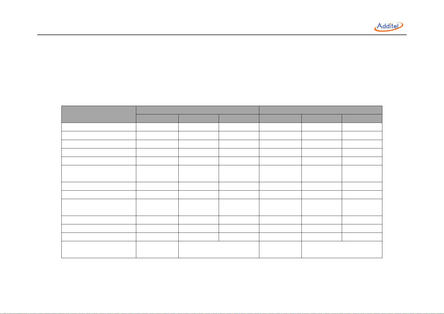
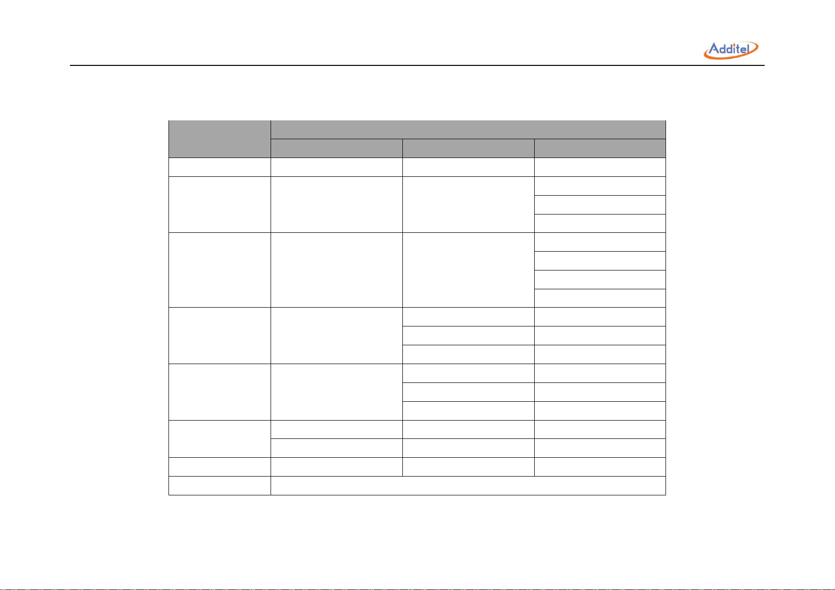
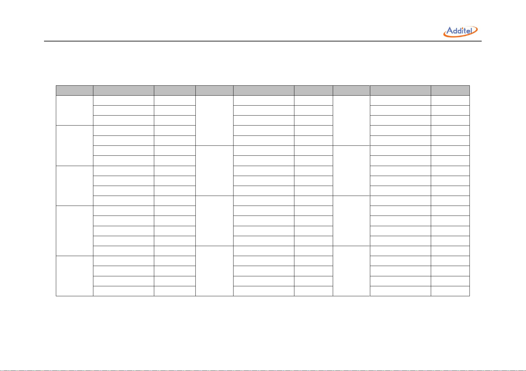
1. Introduction
Specification
ADT875PC
ADT875
-155
-350
-660
-155
-350
-660
Temperature Range
(-40~155)℃
(33~350)℃
(33~660)℃
(-40~155)℃
(33~350)℃
(33~660)℃
mA/mV/V/Ω Measurement
● ● ● DC 24V Output
● ● ●
HART Communication
● ● ● Switch Test
● ● ●
External PRT
(Temperature Control)
● ● ●
Task Function
● ● ● Database
● ● ●
Self Calibration
Auto &
Manual Mode
Auto &
Manual Mode
Auto &
Manual Mode
Manual Mode
Manual Mode
Manual Mode
Application
● ● ● ● ● ● Intelligent Diagnosis
● ● ● ● ● ● Remote Control
● ● ● ● ●
●
Weight
9.9 kg
(21.8 lbs)
8.6 kg
(17.2 lbs)
9.8 kg
(19.6 lbs)
8.5 kg
(17.0 lbs)
1.1 Model Information
Table 1 Model Information
4
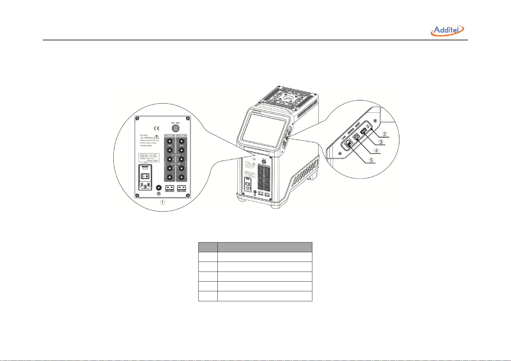
1.2 Basic Structure
No.
Description
1
Electrical Measurement Panel
2
Factory Restore Button
3
USB Port (Host)
4
USB Port (Device)
5
Network Cable Port
Figure 1 Basic Structure
Table 2 Basic Structure
5

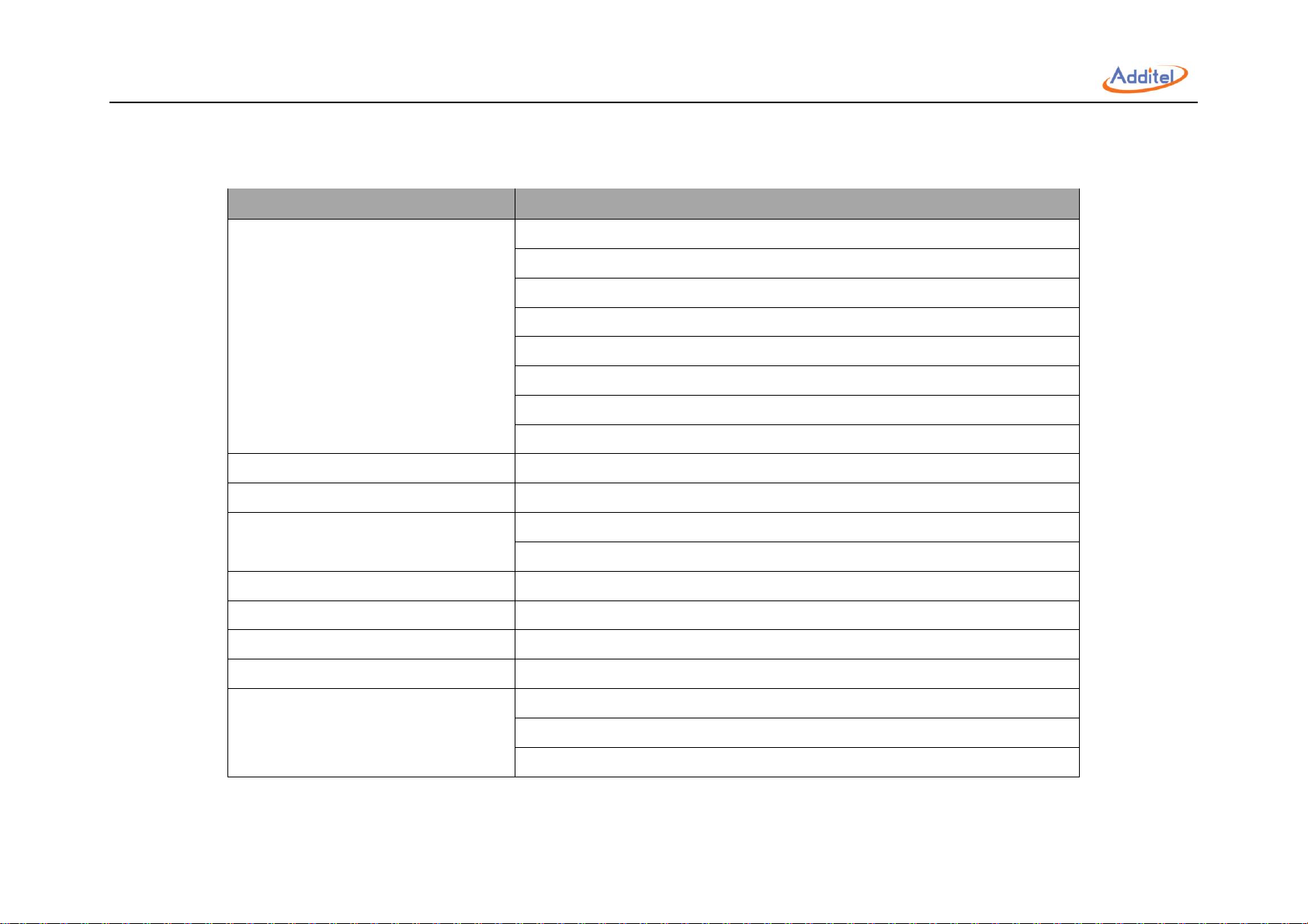
1.3 Features
◆ Three models ranging from -40℃ to 660℃
◆ Portable, rugged, and quick to temperature
◆ Metrology-level performance in stability, uniformity, accuracy and loading effect
◆ Dual-zone control
◆ Process calibrator option provides a multi-channel readout for use with a reference thermometer, RTDs and TCs, as well as task documentation,
switch testing and HART communication
◆ Color touch screen display
◆ Choose your own range option
◆ Set point control by reference PRT
◆ Self-calibration feature
6

1.4 Environmental Conditions
◆Working Temperature: (0~50) ℃ / (32~122) ℉ (Accuracy guarantee: 8℃~38℃ / 46℉~100℉)
◆Storage Temperature: (-20~60) ℃ / (-4~140) ℉
◆Humidity: 0 ~ 90% (0℃ ~ 50℃ or 32℉ ~ 122℉), RH (non-condensing)
◆Atmosphere Pressure: Less than 3,000 m (9,800 ft)
◆Protect Level: IP20
7
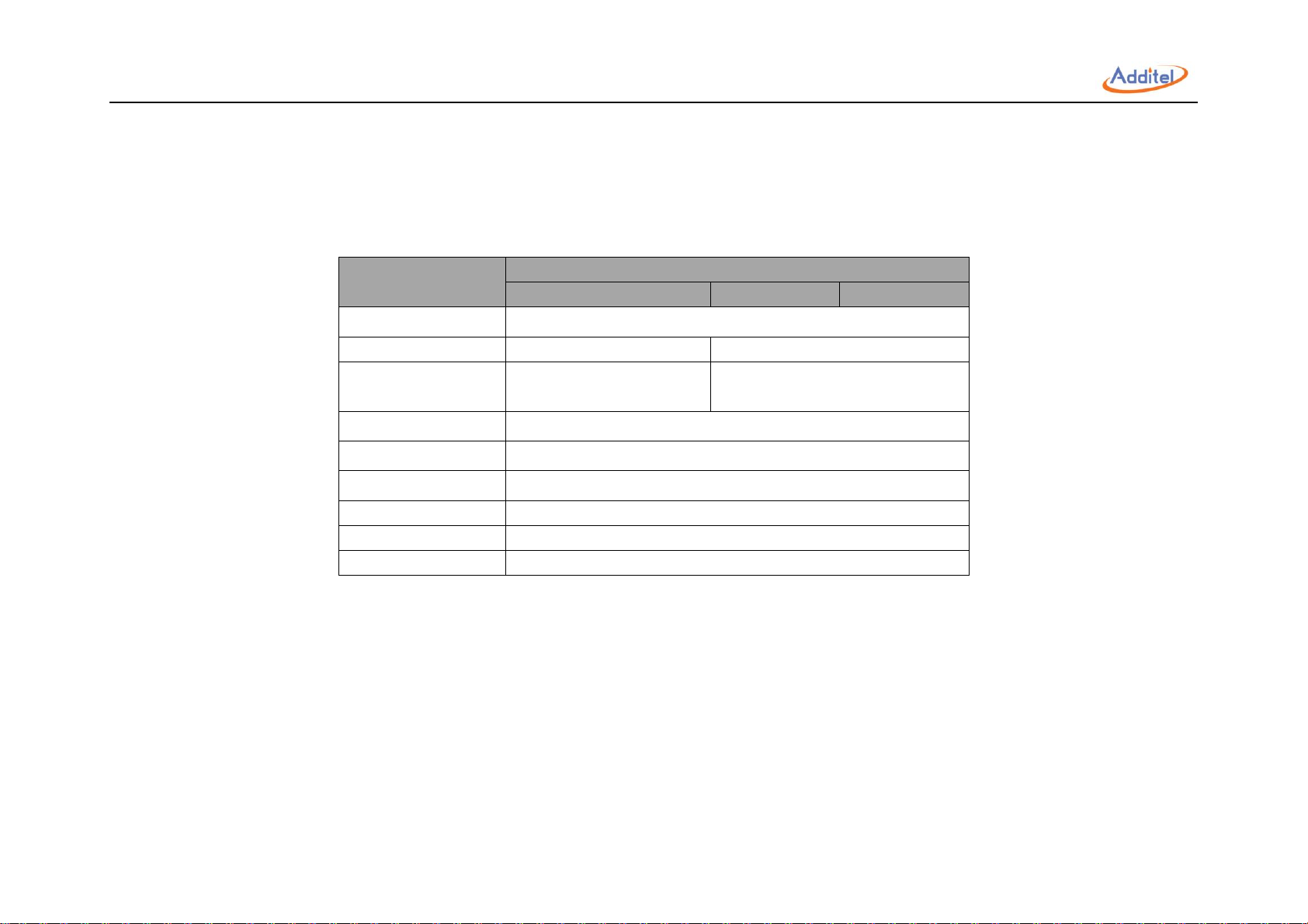
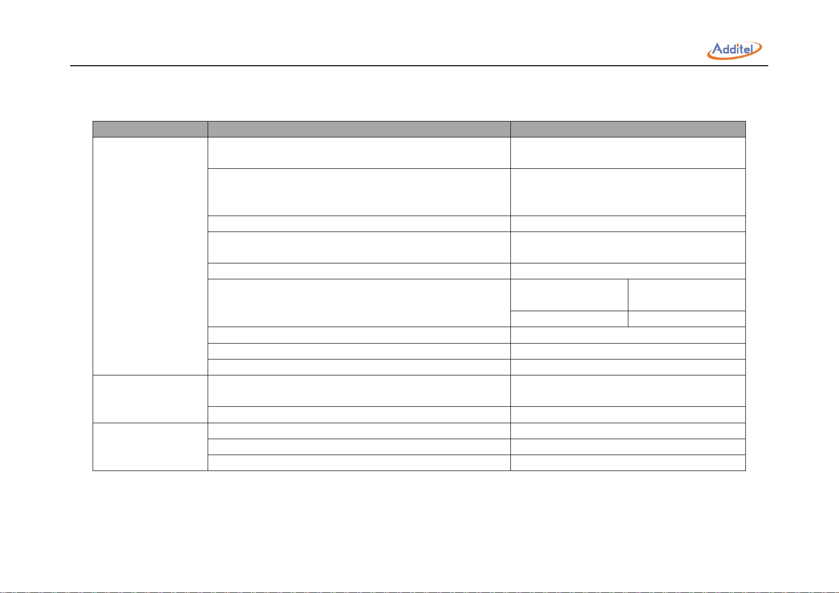
1.5 Technical Specifications
Specification
ADT875PC / ADT875
875-155
875-350
875-660
Dimensions
320 x 170 x 330 mm (12.6 x 6.7 x 13.0 in)
Power Supply
(90-242)VAC,(45-65)Hz, 580W
(90-242)VAC,(45-65)Hz, 1200W
Fuse
230V:4A F 250V
115V:8A F 250V
230V:8A F 250V
115V:16A F 250V
Display
6.5 in (165 mm) color touch screen
Communication
USB A, USB B, RJ45, Wi-Fi, Bluetooth
Localization
English, Chinese, Japanese, Russian, German, French, Italian, and Spanish
Temperature Unit
℃, ℉
, K
Temperature Resolution
0.01℃ / 0.01℉/ 0.01 K
Compliance
CE
1. General:
Table 3 General Specifications
8
2. Dry Well:
Specification
ADT875PC / ADT875
-155
-350
-660
Temperature Range at 23℃
-40°C to 155°C
33°C to 350°C
33°C to 660°C
Display Accuracy
±0.18°C at Full Range
±0.2°C at Full Range
±0.3°C at 33°C
±0.3°C at 420°C
±0.5°C at 660°C
Stability (30 min)
±0.01°C at Full Range
±0.02°C at Full Range
±0.02°C at 33°C
±0.03°C at 50°C
±0.04°C at 420°C
±0.04°C at 660°C
Axial Uniformity
at 60 mm (2.4 in)
±0.07°C at Full Range
±0.04°C at 33°C
±0.05°C at 33°C
±0.1°C at 200°C
±0.3°C at 420°C
±0.2°C at 350°C
±0.5°C at 660°C
Radial Uniformity
±0.01°C at Full Range
±0.01°C at 33°C
±0.02°C at 33°C
±0.015°C at 200°C
±0.05°C at 420°C
±0.02°C at 350°C
±0.1°C at 660°C
Loading Effect
±0.1°C (Display Sensor)
±0.15°C (Display Sensor)
±0.15°C (Display Sensor)
±0.02°C (External Sensor)
±0.015°C (External Sensor)
±0.025°C (External Sensor)
Hysteresis (Display Sensor)
0.025°C
0.03°C
0.1°C
Immersion Depth
150 mm (5.9 in)
Table 4 Dry Well Specifications
9
Insert OD
25.8 mm (1.02 in)
24.8 mm (0.98 in)
Heating Time
13 min: -40°C to 155°C
5 min: 33°C to 350°C
15 min: 33°C to 660°C
5 min: -40°C to 23°C
8 min: 23°C to 155°C
Cooling Time
28 min: 155°C to -40°C
15 min: 350°C to 100°C
23 min: 660°C to 100°C
8 min: 155°C to 23°C
10 min: 100°C to 50°C
12 min: 100°C to 50°C
20 min: 23°C to -40°C
10 min: 50°C to 33°C
12 min: 50°C to 33°C
Typical Time to Stability
10 min
10
3. Electrical Measurement(Only for ADT875PC)
Specification
Description
Readout Accuracy
for 100 ohm PRT
(Probe Accuracy Not Included)
±0.009°C at -40°C
±0.010°C at 0°C
±0.012°C at 50°C
±0.017°C at 155°C
±0.019°C at 200°C
±0.026°C at 350°C
±0.030°C at 420°C
±0.042°C at 660°C
Readout Resolution
1 mΩ
Reference Resistance Range
0 Ω to 400 Ω
Reference Resistance Accuracy
0 Ω to 50 Ω: 0.002 Ω
50 Ω to 400 Ω: 0.004% RD
Reference Characterizations
ITS-90, CVD, IEC-751, Resistance
Reference Measurement Capability
4-wire PRT
Reference Probe Connection
6-pin lemo smart connector
RTD Channels
2
RTD Measurement Accuracy (excl sensor)
0 Ω to 25 Ω: 0.002 Ω
25 Ω to 400 Ω: 0.008% RD
400 Ω to 4K Ω: 0.004% RD
Table 5 Electrical Measurement Specifications
11

RTD Measurement Resolution
0 Ω to 400 Ω: 1 mΩ
400 Ω to 4K Ω: 0.01 Ω
RTD Measurement Resistance Range
0 Ω to 4K Ω
RTD Characterizations
PT10, PT25, PT50, PT100, PT200, PT500, PT1000, CU10, CU50, CU100, NI100, NI120
RTD Connection
Four 4 mm input jacks
RTD Channels
2 channels. Both accept 2, 3, or 4-wire RTDs
TC Channel
2
TC Measurement Channels
Mini TC terminals:
Accepting S, R, K, B, N, E, J, T, C, D, G, L, and U
TC Measurement Accuracy (excl sensor)
Type K:
±0.13°C at 0°C
±0.15°C at 155°C
±0.18°C at 350°C
±0.24°C at 660°C
TC Range
–100 mV to 100 mV
TC Resolution
0.001 mV, Input Impedance <1 MΩ
TC Voltage Accuracy
0.02% RD + 5 µV
Internal CJC Accuracy
±0.35 °C (ambient from 0 °C to 50 °C)
Current Range
–30 mA to 30 mA
Current Accuracy
0.02% RD + 2 µA
Current Resolution
0.001 mA, Input Impedance: < 10Ω
Voltage Range
–30 V to 30 V
12

Voltage Accuracy
±0.02% RD + 2 mV
Voltage Resolution
0.001 V; Input impedance: < 1MΩ
Switch Test
Mechanical or Electrical
DC 24V Output
24 V ±1 V, MAX60 mA
Hart Communication
Optional (ADT875PC Model)
Documentation
Up to 1,000 tasks capable of storing up to 10 results. Each task contains as found and as left data. The
snap shot feature allows for screen captures. Also records auto step and ramp functions.
Temperature Coefficient
0℃ to 8℃ and 38℃ to 50℃
ADT875(PC)-155: ±0.005 °C/°C
ADT875(PC)-350/660: ±0.01 °C/°C
Ref Readout: ±1 ppm FS/°C
RTD Readouts: ±2 ppm FS/°C
TC Readouts: ±5 ppm FS/°C
Current: ±10 ppm FS/°C
Voltage: ±10 ppm FS/°C
13
4. Compliance and Mechanical Testing
Subject
Specification
Description
EMC-Directive
Electrostatic Discharge Immunity
4VK for contact
8KV for air
Radiated Radio-frequency Electromagnetic Field Immunity
10V/m (80MHZ~1GHZ)
3V/m (1.4GHZ~2GHZ)
1V/m (2GHZ~2.7GHZ)
Immunity to Radio-frequency Induced Conducted Disturbance
3V/m (150kHZ~50MHZ)
Voltage Dip
0% for 1 cycle
40% for 10 cycles, and 70% for 25 cycles
Short Interruption
0% for 250 cycles
Pulse Group
1KV (Measuring &
Communication Cable)
5ns, 5kHz
2KV (Power Cord)
50ns, 5kHz
Surge
1KV (Line-to-line) / 2KV (Line-to-ground)
Radio-frequency Radiated Electromagnetic Disturbance Limit
Class B
Radio-frequency Induced Conducted Disturbance Limit
Class B
LVD-Directive
Insulation Voltage
1KV: 875 and 875PC - 350 & 660
2KV: 875 and 875PC - 155
Insulation Resistance
> 1GΩ when tested at 1KV
Mechanical Testing
Vibration Test
2g (10 ~ 500HZ) , 30 minutes for 2 sides
Impact Test
4g, 3 times
Drop Test
500mm
Table 6 Compliance and Mechanical Testing Specifications
14
5. TC Measurement Specification and Calculation (Only for ADT875PC)
TC Type
Temperature (°C )
Error (°C )*
TC Type
Temperature (°C )
Error (°C )*
TC Type
Temperature (°C )
Error (°C )
B
250
±2 J -40
±0.1 R -40
±1.23
350
±1.44
0
±0.1 0 ±0.95
660
±0.84
155
±0.12
155
±0.63 C 0
±0.38
350
±0.16
350
±0.56
155
±0.34
660
±0.21
660
±0.54
350
±0.33 K -40
±0.13 S -40
±1.16
660
±0.38
0
±0.13
0
±0.93 D 0
±0.52
155
±0.16
155
±0.65
155
±0.37
350
±0.19
350
±0.6
350
±0.33
660
±0.25
660
±0.6
660
±0.36 L -40
±0.1 T -40
±0.14 E -40
±0.09
0
±0.1 0 ±0.13 0 ±0.09
155
±0.12
155
±0.13
155
±0.1
350
±0.16
350
±0.15
350
±0.13
660
±0.21
400
±0.15
660
±0.19 N -40
±0.2 U -40
±0.14
G
0
±3.85
0
±0.2 0 ±0.13
155
±0.71
155
±0.19
155
±0.13
350
±0.43
350
±0.2
350
±0.14
660
±0.36
660
±0.24
600
±0.17
Table 7 TC Measurement Specification and Calculation
* Excluding cold junction compensation errors.
15
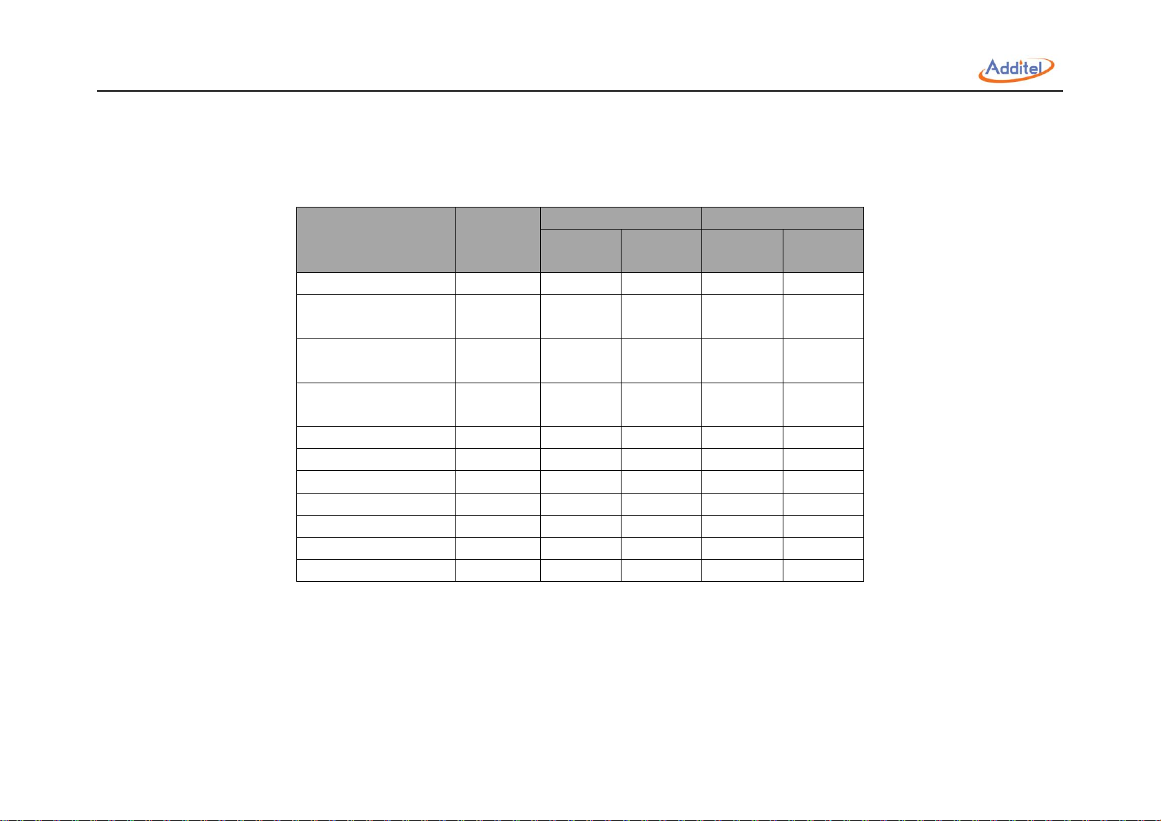
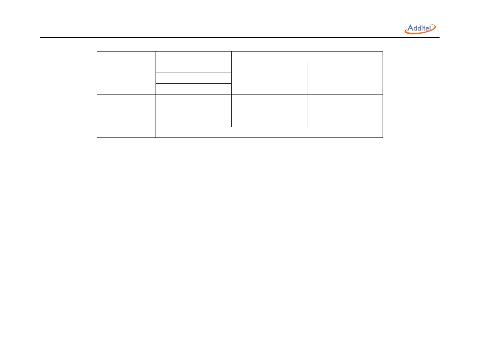
1.6 Standard Equipment
Model
Quantity
ADT875PC
ADT875
ADT-155
ADT-350
ADT-660
ADT-155
ADT-350
ADT-660
Dry well
1 pc. ● ● ● ●
ADT110-875-L-INSERT-X
(Selected Model)
1 pc. ● ●
ADT110-875-H-INSERT-X
(Selected Model)
1 pc. ● ●
Insulation Plug
(Selected Model)
1 pc. ● ●
Silica Gel Plug
1 pc. ● ●
Thermal Shield
1 pc. ● ●
Insert Removal Tool
1 pc. ● ● ● ●
Test Leads
2 set (6 pcs.)
● ● USB Cable
1 pc. ● ● ● ●
CD Manual
1 pc. ● ● ● ●
Certificate of Calibration
1 pc. ● ● ● ●
Table 8 Standard Equipment
16
2. Operation
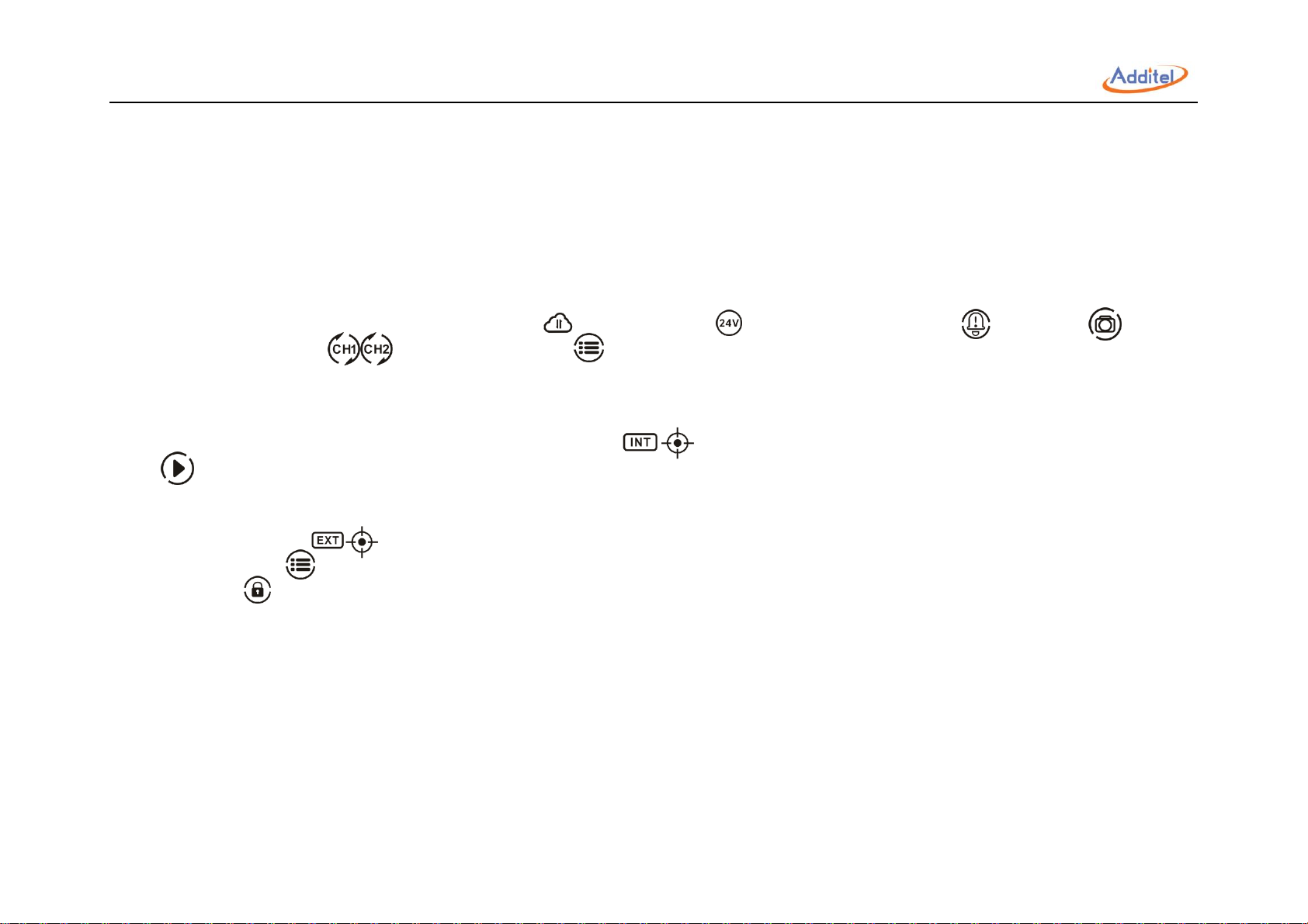
2.1 Main Screen
The main operation interface includes two screens, the upper DUT measurement channel and the lower temperature output channel.
①Status Bar:Includes date and time, cloud storage status , 24V power status , intelligence diagnose center , screenshot , electrical
measurement channel switch , and system menu icon .
Note: All icons (except date and time) on the status bar can be selected via the touch screen to manage and select options.
② DUT measurement window (only for ADT875PC): Includes external measurement readings and sensor type (RTD or TC measurement), automatic
cold junction temperature (only for TC measurement), current or resistance measurements, real-time data of electrical measurement and data analysis
③ Temperature output window: Includes target temperature set point 0.00, real-time temperature data and temperature control play/pause
button .
◆The external PRT sensor can be used as a temperature control sensor: The external sensor window will automatically be displayed when the external
PRT sensor is connected. Please see section 2.3 for how to set the external PRT as control sensor. Once the external PRT has been selected as
control sensor, click on the 0.00 icon in the window to set the target temperature.
④ Screen lock:Press on the top right corner of the screen and select "Screen Lock" to lock the touch display.
◆Unlock:Press on the top right corner of the screen to unlock the touch display.
17
 Loading...