

Page 1

ADT761 Series Automated Pressure Calibrator
Page 2
ADT761 Series Automated Pressure Calibrator
User Manual
Please download the latest version from www.additel.com
[Version: 1903V06]
Additel Corporation
Page 3

STATEMENT
This technical manual provides operating and safety instructions for the ADT761
Series Automated Pressure Calibrator. To ensure correct operation and safety, please
follow the instructions in this manual. Additel reserves the right to change the contents
and other information contained in this manual without notice.
Page 4
Warnings .. .. .. .. ............................................................................................................................. 1
General safety .................. .. .. .. .. .. .. ............................................................................................... 2
1. Introduction ......................................................................................................................... .. .. 3
1.1 Overview ................... ......... ......... ......... ........... ......... ......... ......... .................... ......... ......... ......... ........... . 3
1 .2 Featu res .. ......... ........... ......... ......... ......... .................... ......... ......... ......... ........... ......... ......... ......... .......... 3
1.3 Specifica tions .... ......... ......... ......... .................... ......... ......... ......... ........... ......... ......... ......... ................... 4
2. Installation ................................................................................................................... .. .. .. .. .. ..5
2 .1 Featu res .. ......... ........... ......... ......... ......... .................... ......... ......... ......... ........... ......... ......... ......... .......... 5
2.1.1 Basic struc ture . ......... ......... ......... ........... ......... ......... ......... ........... ......... ......... ......... ......... ........... ........5
2.1.2 Elec trical termin als and signal interf ace ......... ......... ......... ......... ........... ......... ......... ......... .................... .. 6
2.1.3 RS-23 2 interface ... ......... ......... ......... ........... ......... ......... ......... ......... ........... ......... ......... ......... ........... ... 6
2 .1.4 K eypad ......... ......... ......... ......... .................... ......... ......... ......... ........... ......... ......... ......... .................... ..7
2 .1.5 Pneumati c port ... ......... ......... ......... ........... ......... ......... ......... ......... ........... ......... ......... ......... ........... ......8
2.2 Inital prepa ration ........ ......... ......... ......... .................... ......... ......... ......... ........... ......... ......... ......... ........... 8
2.2.1 Batter y in stallation .... ......... ......... ........... ......... ......... ......... ......... ........... ......... ......... ......... ........... ........ 8
2.2.2 Chang ing th e belt strap ..... ......... ......... .................... ......... ......... ......... ........... ......... ......... ......... ......... ...9
2 .2.3 P neumatic connec tion ........ ........... ......... ......... ......... ......... ........... ......... ......... ......... .................... ....... 9
2.2.4 View the displa y .. ......... .................... ......... ......... ......... ........... ......... ......... ......... .................... ......... ..... 9
2.3 Getting started .. ......... ......... ........... ......... ......... ......... ......... ........... ......... ......... ......... .................... ........1 0
2.3.1 Power o n ............. ............. .. ........... .. ............. ............. .. ........... .. ........... .. ............. ............. .. ........... .. ...10
2 .3.2 S etting t he syste m date and time ... ......... ......... ......... ......... ........... ......... ......... ......... ........... ......... ....... 10
2. 3.3 Generating a pressure ....... ......... ........... ......... ......... ......... .................... ......... ......... ......... ........... .......10
3. Func ti on and operation ...................................................................................... .. .. .. .. .. .......... 11
3.1 Disp lay and basic operation ... ......... ......... ........... ......... ......... ......... ......... ........... ......... ......... ......... ....... 11
3.1. 1 Home screen .......... ......... ......... ......... ......... ........... ......... ......... ......... .................... ......... ......... ......... . 11
I
Page 5
3.1 .2 Pre ssure output ...... ........... ......... ......... ......... .................... ......... ......... ......... ........... ......... ......... ........ 12
3.1.3 Press ure measure ... ......... ......... ......... ........... ......... ......... ......... ......... ........... ......... ......... ......... .......... 13
3.1.4 Press ure unit ...... ......... ......... ......... .................... ......... ......... ......... ........... ......... ......... ......... ...............14
3 .1.5 Current output ... ......... ......... ......... ........... ......... ......... ......... .................... ......... ......... ......... ........... .....14
3.1.6 Curre nt / voltage measu re ... ......... .................... ......... ......... ......... ........... ......... ......... ......... ......... ........15
3.1.7 Switc h test ..... ......... ......... .................... ......... ......... ......... ........... ......... ......... ......... ......... ........... ........1 5
3.1.8 Exter nal pressure mo dule ...... ......... .................... ......... ......... ......... ........... ......... ......... ......... ...............16
3.1.9 Scaling ....... ......... ......... .................... ......... ......... ......... ........... ......... ......... ......... ......... ........... ......... ..17
3 .1.10 Ze ro ....... ......... ......... .................... ......... ......... ......... ........... ......... ......... ......... .................... ......... ....17
3.1.11 Step ....... ......... ......... ......... ........... ......... ......... ......... .................... ......... ......... ......... ........... ......... ....17
3.1. 12 Snaps hot .... ......... ......... ......... ........... ......... ......... ......... .................... ......... ......... ......... ........... ......... 19
3.1.1 3 Vent ....... ......... ......... ......... ........... ......... ......... ......... .................... ......... ......... ......... ........... ......... ....19
3.2 HAR T.......... ......... ......... ........... ......... ......... ......... .................... ......... ......... ......... ........... ......... ......... ......20
3 .2.1 Pol l ........ ......... ......... .................... ......... ......... ......... ........... ......... ......... ......... .................... ......... ......20
3 .2.2 Process variab les ......... ......... ........... ......... ......... ......... ......... ........... ......... ......... ......... .................... ...21
3 .2.3 Set up ....... ......... ......... ......... ........... ......... ......... ......... .................... ......... ......... ......... ........... ......... ....22
3.2.4 Servi ce .. ......... ......... ........... ......... ......... ......... .................... ......... ......... ......... ........... ......... ......... ......23
3.3 Typ ical applica tions in the m ain screen ........... ......... ......... ......... .................... ......... ......... ......... ..........2 4
3 .3.1 Calib rating pre ssure gaug es ..... ........... ......... ......... ......... ......... ........... ......... ......... ......... .................... 24
3 .3.2 Calib rating p ressure tr ansmitters. ......... ......... ......... ......... ........... ......... ......... ......... ........... ......... ......... 24
3.3. 3 C alibratin g H ART tr ansmitters ... ......... ......... ......... .................... ......... ......... ......... ........... ......... ......... .25
3 .3.4 Calib rating pre ssure swit ches .............. ......... ......... ......... ........... ......... ......... ......... .................... ......... 26
3.3 .5 Calibra ting I/P converters ...... ........... ......... ......... ......... .................... ......... ......... ......... ........... ......... ...27
3.3. 6 Calibr ating is olator / conve rt / si gnal-acqu iring de vices .. ......... ......... ........... ......... ......... ......... ..............27
3.4 Setup ....... .................... ......... ......... ......... ........... ......... ......... ......... .................... ......... ......... ......... .......28
3.4.1 Control setup . ......... ......... .................... ......... ......... ......... ........... ......... ......... ......... ......... ........... ........2 8
3 .4.2 24V power .... ......... ......... ......... ........... ......... ......... ......... ........... ......... ......... ......... ......... ........... ......... 29
II
Page 6

3.4.3 Display setup . ......... ......... ........... ......... ......... ......... ......... ........... ......... ......... ......... .................... ........2 9
3.4.4 Date and t ime .. ......... ......... ......... ........... ......... ......... ......... .................... ......... ......... ......... ........... .......30
3.4.5 Langu age ......... ......... ......... ......... .................... ......... ......... ......... ........... ......... ......... ......... .................31
3.4.6 Fa ctory default ......... ......... .................... ......... ......... ......... ........... ......... ......... ......... .................... .......31
3.4 .7 Too ls ....... ......... ......... ......... ........... ......... ......... ......... .................... ......... ......... ......... ........... ......... .....31
3 .4.7.1 Leak test ... ......... ......... ......... ........... ......... ......... ......... .................... ......... ......... ......... ........... ........3 1
3.4.7.2 Vent ... ......... ......... ......... ........... ......... ......... ......... ........... ......... ......... ......... ......... ........... ......... .....33
3.4.7.3 Unit conv ersion ... ......... ........... ......... ......... ......... ......... ........... ......... ......... ......... ........... ......... .......33
3.4 .7.4 Help ... ......... ......... ........... ......... ......... ......... ......... ........... ......... ......... ......... .................... ......... .....34
3 .4.8 Inf ormation . ......... ......... ........... ......... ......... ......... ......... ........... ......... ......... ......... .................... ......... ..34
3.4.9 System Calibrati on ..... ......... ........... ......... ......... ......... .................... ......... ......... ......... ........... ......... .....34
3.4.9.1 Current / voltag e measur e ...... .................... ......... ......... ......... ........... ......... ......... ......... ..................35
3.4.9.2 Current s ource .... ......... ........... ......... ......... ......... ......... ........... ......... ......... ......... ........... ......... .......35
3.4 .9.3 High / lo w range ... ......... .................... ......... ......... ......... ........... ......... ......... ......... .................... ......35
3.4 .9.4 Externa l pressure module ... ........... ......... ......... ......... .................... ......... ......... ......... ........... ......... .36
3. 4.9.5 Se lf tune . ......... ......... ......... ........... ......... ......... ......... .................... ......... ......... ......... ........... ......... .36
3 .4.10 RS23 2 setup . ......... ......... ......... ........... ......... ......... ......... .................... ......... ......... ......... ........... .......36
3.5 Task .. ......... ......... ......... .................... ......... ......... ......... ........... ......... ......... ......... .................... ......... ......36
3 .5.1 Calib rating dia l pressure gauges . ........... ......... ......... ......... .................... ......... ......... ......... ........... .......37
3.5.2 Calibr ating digita l pressure ga uges ....... ......... ......... ......... .................... ......... ......... ......... ........... ........4 0
3.5.3 Calibr ating pressu re transmitt ers ........ ......... ......... .................... ......... ......... ......... ........... ......... ......... .40
3.5.4 Calib rating HART t ransmitte rs .. ......... ......... ......... ........... ......... ......... ......... ......... ........... ......... ......... ..43
3.5.5 Calibrating pressure s witches .... ......... ......... ......... ......... ........... ......... ......... ......... .................... ......... .44
3.5.6 Ca librating I/ P conver ters ..... ........... ......... ......... ......... ........... ......... ......... ......... ......... ........... ......... ....45
4.Troubleshooting....... .. ..................... ..................... .. ..................... .. ..................... ..................... 47
4.1 Device informat ion ... .................... ......... ......... ......... ........... ......... ......... ......... .................... ......... ......... 47
4.2 P rompt.... ......... .................... ......... ......... ......... ........... ......... ......... ......... .................... ......... ......... ......... 47
II I
Page 7
4.3.1 Check ing for leaks ... ......... ......... ......... ........... ......... ......... ......... .................... ......... ......... ......... ......... 48
4.4 I nstability ...... ......... ......... .................... ......... ......... ......... ........... ......... ......... ......... ......... ........... ......... ..49
5. Special Application for Barometric Pressure .......................................... .. .. .. .. .. ......................50
5.1 ADT761 B asic diffe rences... ......... .................... ......... ......... ......... ........... ......... ......... ......... ...................5 0
5.2 Gas head cor rection ......... ......... ......... ........... ......... ......... ......... ........... ......... ......... ......... ......... ........... .50
5.3.1 Digital b arometer ... ......... ........... ......... ......... ......... ......... ........... ......... ......... ......... ........... ......... ........5 0
5 .3.2 Mercu rial bar ometer ... ......... ........... ......... ......... ......... .................... ......... ......... ......... ........... ......... ....52
5.3.3 Aner oid barometer ... ......... ......... ........... ......... ......... ......... ........... ......... ......... ......... ......... ........... ......53
5.3.4 Bar ometer altimet er ......... ........... ......... ......... ......... .................... ......... ......... ......... ........... ......... .......54
5 .3.5 Pressure trans mitter ....... ........... ......... ......... ......... .................... ......... ......... ......... ........... ......... ........5 5
5. 3.6 Pressure switch ..... ......... ........... ......... ......... ......... ......... ........... ......... ......... ......... .................... ........5 5
Appendix A Data Sheet ...... ......... ......... ........... ......... ......... ......... .................... ......... ......... ......... ........... ........5 6
A.1 En vironment . ......... ......... .................... ......... ......... ......... ........... ......... ......... ......... .................... ......... .. 56
A.2 Power ..... ......... ......... .................... ......... ......... ......... ........... ......... ......... ......... .................... ......... ........5 6
A.3 Tech nical spe cification ......... ........... ......... ......... ......... ......... ........... ......... ......... ......... ........... ......... .......56
IV
Page 8
Warnings
Additel's wa rranty will not c over this app lication.
◆ Do not apply pr essures great er than the max imum working pr essure. Ad ditel's war ranty will not co ver this
applicati on.
◆ Not for use in fl ammable, high h umidity, or dusty envir onments.
◆ Only charge w ith supplied ba ttery (mode l 9722) and make su re the batter y has not short c ircuited.
1
Page 9
General safety
◆ If condensa tion has occurr ed, thoroug hly dry out the 761 b efore start up.
◆ Connectin g the REF/FLT port to the r eference port o f unit under te st (UUT) with a s mall diff erential pres sure range
might resul t in control prob lems over tim e as the environmental tempe rature chan ges. Disconne ct the ports an d
reconnect t o resolve contr ol issues.
◆ The vent port s hould not face th e operator du ring venting.
◆ Do not apply ex cessive volta ge or current t o the electrica l terminals .
◆ Do not use any ad apter other tha n Additel mode l 9818. Charge as s oon as the batt ery symbol in dicates.
◆ If the calibr ator is not worki ng properly, turn it off, remove the b attery and co ntact Addite l.
◆ Do not remove t he battery whil e it is chargin g or when the calib rator is in use .
◆ Before turn ing off the c alibrator, mak e sure the syst em pressure i s reduced to the at mosphere pr essure.
2
Page 10
1. Introduction
1.1 Overvie w
The ADT7 61 Series Au tomated Pre ssure Calibra tor generat es pneumatic pr essure rapi dly with high p recision and
stability. Precisio n measurement a nd digital co ntrol techn ology develop ed by Additel ar e used in the ADT7 61.
With dual pre ssure sensors , precision e lectrical mea surement an d source, the AD T761calibra tor provide s many
differe nt ways to cali brate and test a va riety of devi ces such as, di al pressure gau ges, digita l pressure gaug es,
pressure tr ansmitters, p ressure swi tches and I/P converte rs.
1.2 Feature s
◆ Automatic ally generate s pressure wi th high precisi on.
◆ Excellent r esponse time.
◆ HART co mmunicati on.
◆ Loop power su pply at 24V.
◆ Task manageme nt firmware whi ch stores and a rchives test pr ocedures an d results.
◆ 800x480 TFT LCD with f riendly HMI .
◆ Multi-lin gual display.
◆ Rechargea ble Li battery.
◆ Light weigh t and portable.
◆ Built-in le ak test.
◆ Updateabl e firmware.
3
Page 11
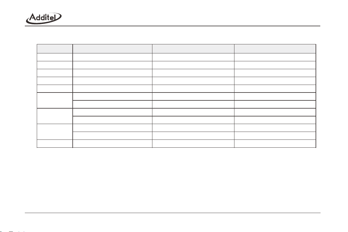
1.3 Specifications
Model Pressure Ra nge Range 1 Range 2
ADT76 1-LLP
ADT76 1-D
ADT76 1-L
ADT76 1-M
ADT76 1-H
ADT76 1-LA
ADT76 1-MA
ADT76 1-HA
ADT76 1-BP
-25 to 25 m bar (-1 0 to 10 inH O)
-0.95 t o 1 bar (-1 3.5 to 15 p si)
-0.95 t o 7 bar (-1 3.5 to 10 0 psi)
-0.90 t o 25 bar (- 13 to 375 p si)
-0.90 t o 40 bar (- 13 to 600 p si)
-0.95 t o 7 bar (-1 3.5 to 10 0 psi)
0.05 to 8 b ar.a (1. 2 to 115 psi .a)
-0.90 t o 25 bar (- 13 to 375 p si)
0.1 to 26 b ar.a (1. 7 to 390 ps i.a)
-0.90 t o 40 bar (- 13 to 600 p si)
0.1 to 41 b ar.a (1. 7 to 615 ps i.a)
100 to 12 00 hPa
-2.5 to 2 .5 mbar ( -1 to 1 inH O)
2
-25 to 25 m bar (-1 0 to 10 inH O)
-0.95 t o 2.5 bar ( -13.5 t o 35 psi)
-0.90 t o 2.5 bar ( -13 to 35 p si)
-0.90 t o 2.5 bar ( -13 to 35 p si)
-0.95 t o 2.5 bar ( -13.5 t o 35 psi)
0.05 to 3 .5 bar.a ( 1.2 to 50 p si.a)
-0.90 t o 2.5 bar ( -13 to 35 p si)
0.1 to 3. 5 bar.a (1 .7 to 50 ps i.a)
-0.90 t o 2.5 bar ( -13 to 35 p si)
0.1 to 3. 5 bar.a (1 .7 to 50 ps i.a)
100 to 12 00 hPa
2
2
-25 to 25 m bar (-1 0 to 10 inH O)
-0.95 t o 1 bar (-1 3.5 to 15 p si)
0 to 7 bar (0 t o 100 psi )
0 to 25 bar ( 0 to 375 ps i)
0 to 40 bar ( 0 to 600 ps i)
-0.95 t o 7 bar (-1 3.5 to 10 0 psi)
0.05 to 8 b ar.a (1. 2 to 115 psi .a)
-0.9 to 2 5 bar (-1 3 to 375 ps i)
0.1 to 26 b ar.a (1. 7 to 390 ps i.a)
-0.9 to 4 0 bar (-1 3 to 600 ps i)
0.1 to 41 b ar.a (1. 7 to 615 ps i.a)
N/A
Additel reserves the right to change specifications and other information contained in this manual without notice.
2
4
Page 12
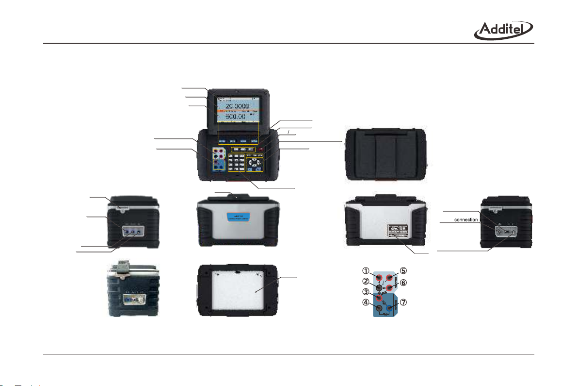
2. Installation
2.1 Feature
2.1.1 Basic s tructure
Status Bar
Measure terminals
Source terminals
Measure
Source
Function Keys
Shortcut Keys
On Off
HART, Task and Setup keys
Control Keys
Strap Connections
Vent Port
Outlet Port
REF/FLT Port
Lock
/FLT
/FLT
Portable Automated Pressure Calibrator
Numeric Keypad
Battery
Label
Rs232 Interface
Pressure module
Power supply input
Figure 2-1 Basic structure
5
Page 13
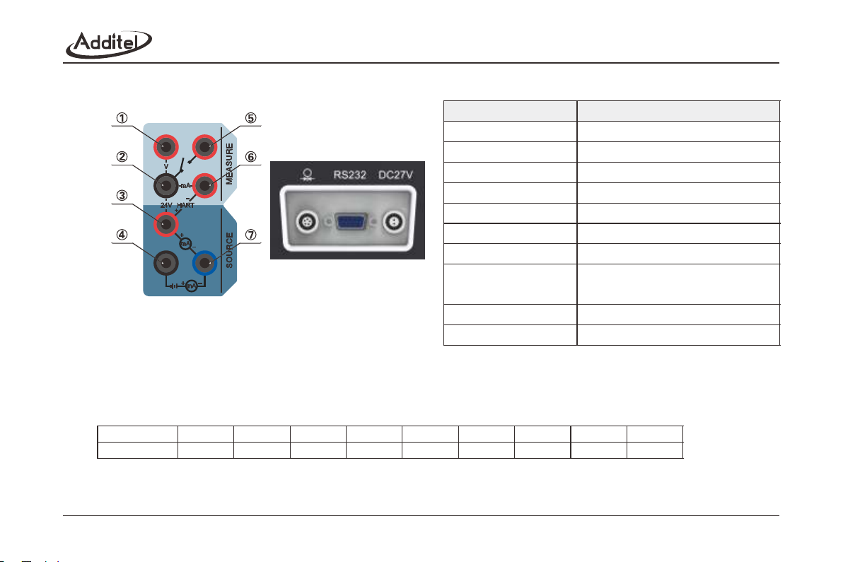
2.1.2 Electrical terminals and signal interface
Figure 2-2 Electrical terminals and signal interface
Terminal and Interface
6 and 2
1 and 2
5 and 2
3 and 6
7 and 4
3 and 7
3 and 2
Pressure module
connection
RS-232 interface
DC27V input
Introduction
Current measure.
Voltage measure.
Switch test.
HART communication.
Current output (external power).
Current output (internal power).
Loop power supply at 24V.
Works with ADT160 pressure modules.
Computer interface.
Power supply and battery recharge.
Table 2-1 Electrical terminals and signal interface
2.1.3 RS-232 interface
◆ The RS-232 interface is designed as a 9 pole SUB-D-socket, Pin-configuration see Figure table 2-2.
Pin
Configuration1N.C.
TX
2
3
RX
4
N.C.
5
GND
6
N.C.
7
N.C.
8
N.C.
N.C.
Table 2-2 Pin configurations
9
6
Page 14
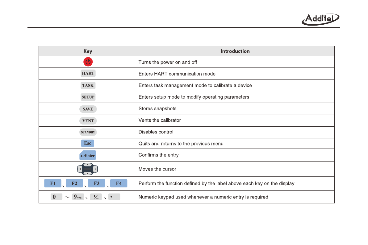
2.1.4 Keypa d
Table 2-3 Key functions
7
Page 15

2.1.5 Pneumatic port
control is (0~100) cc and should not be exceeded.
◆ REF/FLT port: ADT761-BP (port is blocked). ADT761-LLP/D (port is the reference or low port. Leave open to measure in
gauge mode). All other ADT761 models (port contains a filter for internal pump. The filter should be changed when dirty,
as shown in figure 2-3).
◆ VENT port: The port which pressure is released from the system.
2.2 Initial preparation
2.2.1 Battery installation
As shown in Figure 2-4, install the model 9722 battery in the bottom of calibrator with a 3mm wrench.
PN:1220211190 FILTER
PN:1220211189 FILTER CAP
Figure 2-4 Battery installation
Figure 2-3 How to change filter
8
Page 16
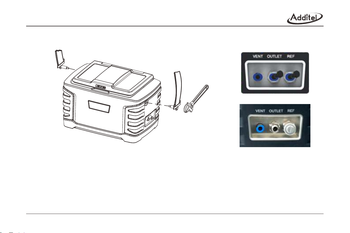
2.2.2 Chang ing the belt stra p
As shown in Figu re 2-5, change th e belt strap wi th an 8 inch wrench .
/FLT
Figure 2-6 Pneumatic connection
Figure 2-5 Changing the belt strap
Figure 2-7 Pneumatic connection
/FLT
2.2.3 Pneum atic connecti on
As shown in Figu re 2-6 shows pneu matic conne ction of ADT761- LLP and ADT761-D.Fi gure 2-7 show s pneumatic
connectio n of ADT761-L, AD T761-LA, ADT 761-M, ADT76 1-MA, ADT761 -H and ADT761- HA., connec t the
OUTLET an d REF/FLT ports to the UU T or use plug s when necess ary.
2.2.4 Vie w the display
Push the fron t lock to the right a nd raise the sc reen to the pro per position.
9
Page 17
2.3 Getting started
2.3.1 Power on
◆ Press to turn the power on.
◆ The startup screen shows the manufacturer's logo.
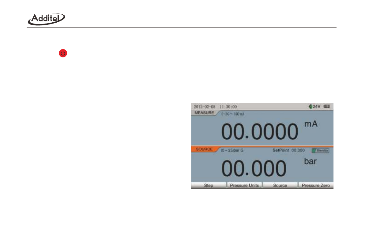
◆ After a short time the system enables the home screen and enters STANDBY mode as shown in Figure 2-8.
◆ Connect the power supply for charging if power is low.
2.3.2 Setting the system date and time
Refer to section 3.4.4 to set date and time.
2.3.3 Generating a pressure
Ensure the source screen is highlighted, enter an
appropriate pressure value using the numeric
keypad, press enter and calibrator will generate
and control to the desired pressure (see section 3.1.2).
Figure 2-8 Main screen
10
Page 18
3. Function and Operation
3.1 Display a nd basic operat ion
3.1.1 Home Sc reen
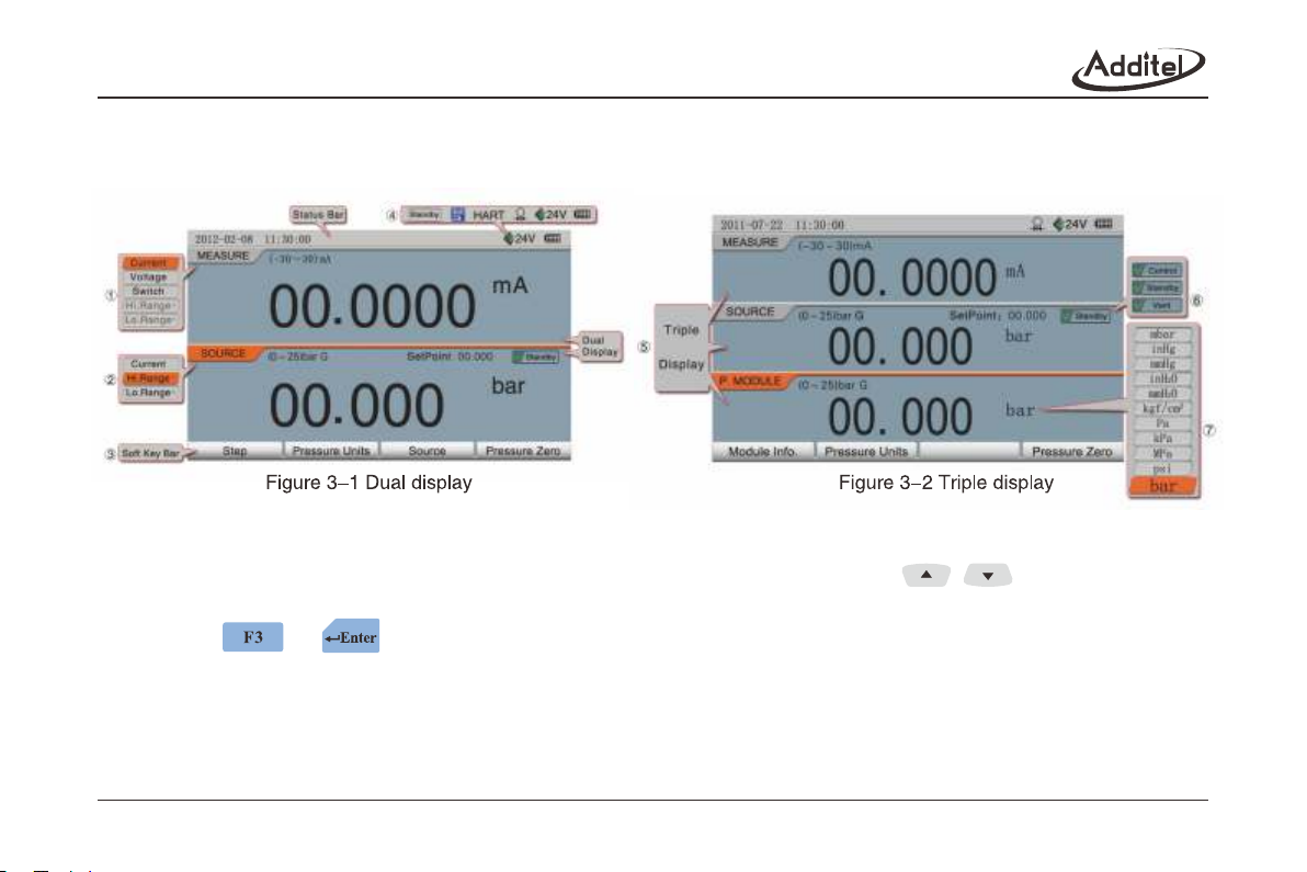
The home sc reen normal ly contains a MEA SURE window a nd a SOURCE windo w (see figure 3 -1). If you sel ect
the Triple Dis play in the SETUP mode and con nect the exte rnal pressu re module, thre e windows wil l be shown
(see figure 3 -2). To selec t between the MEA SURE and SOUR CE window, pre ss / till the desir ed
window is hig hlighted in ora nge. The so ftkeys disp layed at the bottom of the scree n relate to the s elected mode.
Press or to sel ect what is bei ng measured in th e MEASURE win dow or the pres sure sensor
used when in th e SOURCE window.
① Items of MEAS URE: Current me asure, volt age measure , switch, high pr essure rang e, low pressure r ange, or
pressure mo dule.
② Items of Sour ce: Current sou rce, high pre ssure range , low pressure ra nge, or press ure module.
11
Page 19
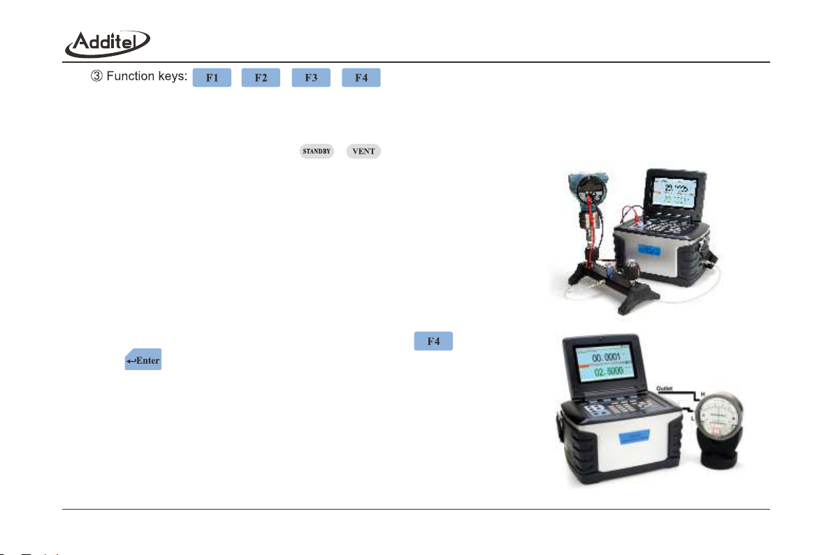
④ Status bar: Run mode (not visible in the home screen), snapshot, HART online, pressure module online, 24V
、 、 、
power status, battery level.
⑤ Triple display: If the triple display is enabled, then three windows will be shown when the pressure module is connected.
⑥ The pressure output mode: Press / to change to standby mode, exit the control mode, or to vent the
calibrator.
⑦ Pressure units menu: Up to 11 selectable pressure units.
3.1.2 Pressure output
1. Select High/Low Pressure Range in source mode.
◆ The calibrator must be vented or in standby mode.
◆ The calibrator will automatically vent when switching ranges.
2. Connection: Complete the pneumatic connection as shown in
Figure 3-3 or Figure 3-4.
3. Entering a value
◆ Use the numeric keypad to enter the value, and press
/ to confirm.
◆ If there is no operation within 10 seconds, the calibrator will
automatically cancel the entry.
◆ The value must meet the control range of the calibrator.
◆ The maximum negative pressure is -13.5 psi (-0.95 bar).
But this is dependent on the local atmospheric pressure.
◆ The value cannot exceed the control range of the CONTROL SETUP,
or the calibrator will prompt the user to reset the limits.
12
Figure 3-3 Gauge pressure source
REF/FLT
Figure 3-4 Differential pressure source
Page 20

◆ If you've selected the low pressure sensor and enter a pressure value that exceeds the low sensor range, then the
calibrator will ask if you would like it to automatically switch to the high pressure sensor.
4. Control
◆ Confirm the set value, and the calibrator will automatically start controlling to the set point.
◆ The control may be paused at any time by pressing .
◆ The following functions are disabled in the CONTROL mode: Pressure Zero (Section 3.1.10), Step (Section 3.1.11),
Leak Test (Section 3.6.1), VENT (Section 3.6.2), and Calibration (Section 3.7).
5. Stabilize
◆ When the calibrator reaches a stable condition as defined in the CONTROL SETUP (Section 3.4.1), the color of the
displayed value will change from black to green.
3.1.3 Pressure measure
1. Select the High/Low Pressure Range in measure mode.
/FLT
◆ The calibrator will vent as it switches ranges.
2. Connection: Complete the pneumatic connection to the
external pressure source as shown in Figure 3-5.
3. External pressure source:
◆ Avoid applying pressure greater than the maximum working
pressure to the calibrator.
◆ If the value falls outside the current pressure range, the color
of the displayed value will change from black to red and the
Figure 3-5 Pressure measure
calibrator will alarm.
◆ If the external pressure is potentially damaging to the calibrator, it will automatically vent and an over pressurization
prompt will appear.
13
Page 21
3.1.4 Pressure unit
◆ Press to select a pressure unit in the SOURCE window,or when measuring an external pressure module in the
MEASURE window.
◆ The selected units relate to the range and resolution of the internal sensors (Section3.4.3).
3.1.5 Current output
1. Select Current in SOURCE mode
◆ The calibrator must be vented or in standby mode to change from sourcing pressure to current.
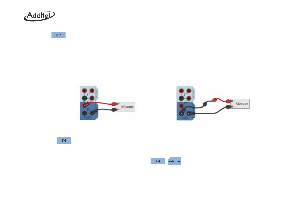
2. Connection: Complete the electrical connection as shown in Figure 3-6 or Figure 3-7.
Figure 3-6 Internal 24V power supply
3. Power supply
◆ Press to select internal loop power or external loop power.
◆ The default setting for the DC24V power is to remain on unless external loop power is selected
4. Entering a value
◆ Use the numeric keypad to enter a value, and press / to confirm.
◆ If there is no operation within 10 seconds, the calibrator will automatically cancel the entry.
◆ The value must be within the range of (0~22) mA.
Figure 3-7 External power supply
14
Page 22

3.1.6 Current/voltage measure
1. Selected Current or Voltage in MEASURE mode.
◆ Do NOT apply voltage / current that exceeds the current / voltage range.
◆ Press to zero.
◆ If the value falls outside the current/voltage range, the color of the display value will change from black to red and the
calibrator will issue the alarm.
◆ If the value exceeds the measure limit of the calibrator, the value will be shown as “_ _ _ _ _ _ _ _” and the
calibrator will issue the alarm.
2. Connection: complete the electrical connection as shown in Figure 3-8 or Figure 3-9.
Figure 3-8 Current measure
1. Select Switch in MEASURE mode.
2. Connection: Complete the electrical connection as shown in Figure 3-10.
Figure 3-9 Voltage measure
Figure 3-10 Switch test
15
Page 23
3. Trip values
◆ The switc h test will onl y work if the SOURC E window is set t o source pres sure.
◆ The calib rator recor ds the trip value s and the state
(open/clo se) of the switch .
◆ Press to eras e trip values .
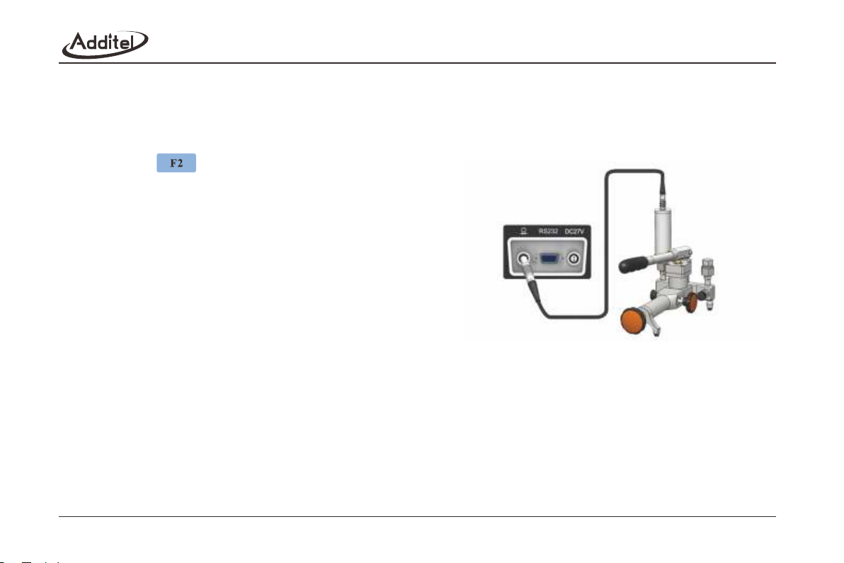
3.1.8 Exter nal pressure mo dule
1. Connecti on: complete th e pressure mo dule connecti on
as shown in Fig ure 3-11.
2. Display
◆ A s ymbol will be sho wn on the statu s bar indicating an
external pr essure module i s online. The home scree n
will show thr ee windows with t he TRIPLE D ISPLAY
when it is enab led in DISPLAY SETU P.
◆ Both the MEAS URE and SOURCE ca n be changed to
read the exte rnal pressure m odule.
◆ If the value fa lls outside the e xternal pre ssure modul e's
pressure ra nge, the color of t he displaye d value will ch ange from black t o red and the cal ibrator will is sue
the alarm.
◆ If the value ex ceeds the measu re limit of the e xternal pre ssure module, t he value will b e shown as
“_ _ _ _ _ _ _ _”and the ca librator will i ssue the alar m.
Figure 3-11 External pressure module
16
Page 24
3. Operations
◆ Press to select a pressure unit (Section 3.1.4 and Table 3-2).
◆ Press to display the information of the pressure module.
3.1.9 Scaling
◆ When a current or voltage is being measured, the calibrator can scale the signal to display pressure or % of full scale.
◆ Press to set correlative parameter.
3.1.10 Zero
◆ When offset occurs a Pressure Zero or Electrical Zero can be applied to the High/Low Range pressure, Current/Voltage
measure, or external pressure module.
◆ Zero can be done within 1%FS of the pressure or 0.1%FS of the Current/Voltage.
3.1.11 Step
1.Setup
◆ Press to setup the step parameter in SOURCE mode.
◆ Starting point (Vs) and Ending point (Ve).
1) They cannot be equal (if Vs<Ve, ascend first and Vmin=Vs, Vmax=Ve. If Vs>Ve, descend first and Vmin=Ve, Vmax=Vs).
2) The unit is the same as the unit of Source item.
◆ Step Mode and size. The output values of the steps are calculated as follows:
1) The step size of point number(N), and the output values(n):
Vmin+ (n-1) * ( Vmax-Vmin ) / (N - 1), n = 1,2,… (n-1) ≦ N -1
17
Page 25
Vmin+ (n-1) * E, n = 1,2,… (n-1) * E ≦ Ve
3)The step of scale(P), and the output values(n):
Vmin+ ( Vmax-Vmin ) * (n-1) * P%, n = 1,2,… (n-1) * P% ≦ 1
note: ① The range must be divisible by the step size.
② The step range cannot exceed the range of the calibrator.
③ The step range cannot exceed the control range of the CONTROL SETUP, or the calibrator will prompt the
user to reset the limits.
◆ Stroke mode: select the One Way or the Two Way.
◆ Wait Time:
1) For the auto mode only, the range is 1~3600 seconds.
2) When SOURCE is set to Current the wait time is time between mA steps.
3) When SOURCE is pressure, the wait time is the duration after the pressure has stabilized.
2. Run
◆ Press to start.
◆ Manual mode: press to advance to the next step and then press to end.
◆ Auto mode: the calibrator will run the steps automatically. Press to pause or continue, and then press
to end.
18
Page 26
3.1.12 Snapshot
1. Snapshot
◆ In the home screen press to store a record that includes a record of the date, time, source value, measure
value, and 24V status. The snapshot symbol flashes on the status bar.
◆ The snapshot files are named numerically.
◆ Store up to 900 snapshots.
◆ The snapshot function can be used in HART mode.
2. Management
◆ To view the snapshot list, press and hold for two seconds or press and select the snapshot item.
◆ Press / to page up and down.
◆ Press / to delete the record(s).
/FLT
◆ The record(s) can be uploaded to a computer by the RS232 port to
Additel/Land software.
3. Prefix
◆ Press to add a prefix to the file name.
◆ Allows for an alphanumeric entry or press numerical keypad to input special
codes.
3.1.13 Vent
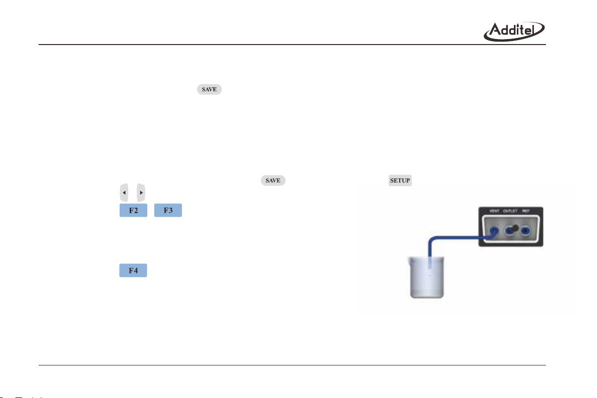
Figure 3-12 Vent
◆ The calibrator opens the vent valve to reduce pressure to atmosphere pressure.
◆ When venting dust or contaminants are blown out through the vent port as shown in Figure 3-12.
19
Page 27
◆ Do not point th e Vent port toward t he operator d uring venting .
◆ Will end the le ak test.
◆ Press to stop a ny pressure gen eration or co ntrol and ret urn
to barometr ic pressure. Pr ess again to cl ose the vent va lve
and switch to S tandby mode.
◆ When settin g a decreasing pr essure valu e, the calibrat or will
automatic ally vent when th e pressure re aches the Vent P
pressure in t he Control Setu p.
3.2 HART
3.2.1 Poll
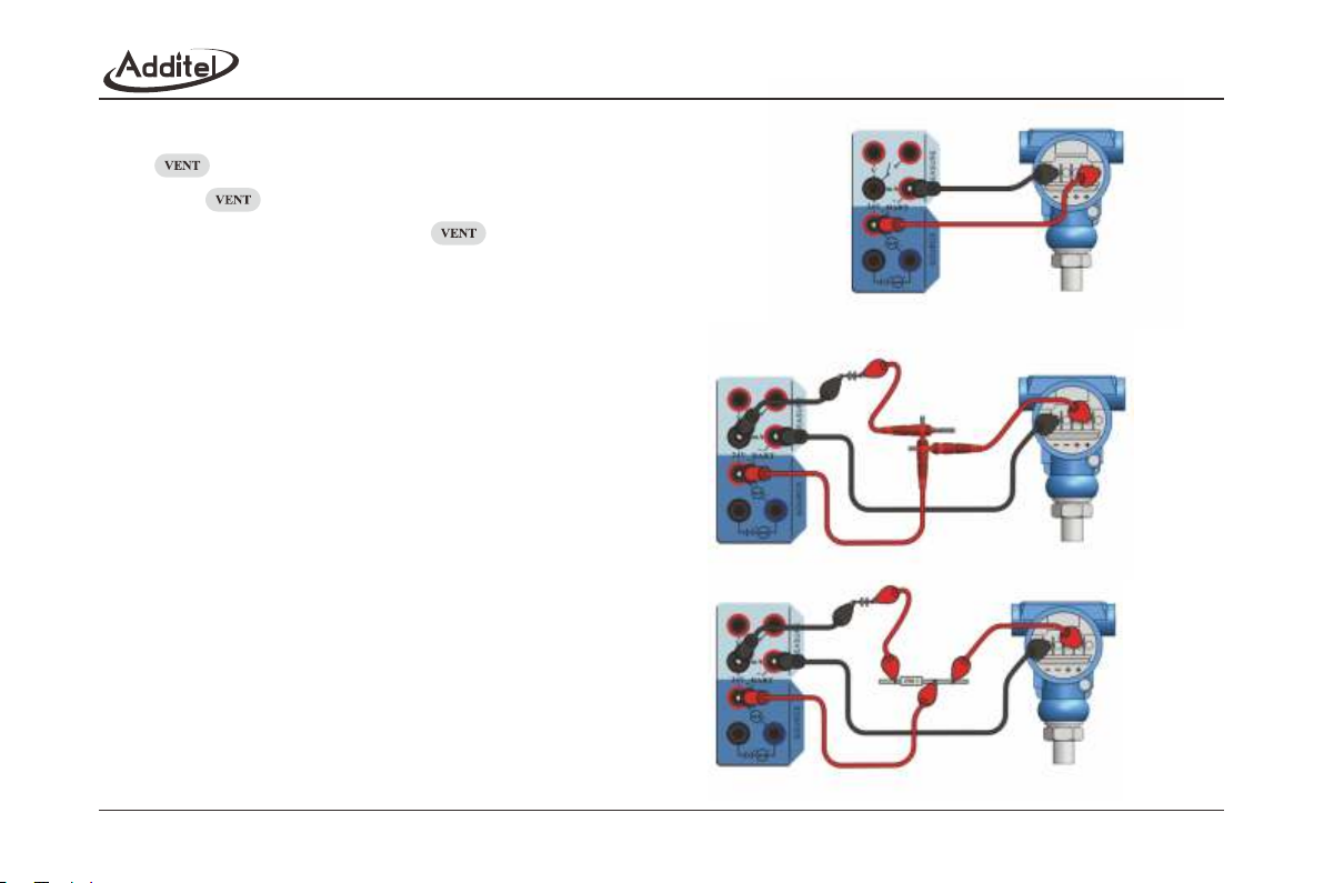
1. Connect
◆ Use the inter nal series resi stor and
internal 24 V loop power supp ly as
shown in Figu re 3-13.
◆ Use the inter nal series resi stor and
external lo op power supply a s shown
in Figure 3-1 4.
◆ Use the exter nal series resi stor and
external lo op power supply a s shown
in Figure 3-1 5.
20
Figure 3-14 Internal series resistor and external loop power supply
Figure 3-15 External series resistor and external loop power supply
Figure 3-13 Internal series resistor
and internal 24V loop power supply
Page 28
◆ Ensure a proper connection (see connections above). From the home screen, press to start the HART function.
◆ The calibrator will poll address 0. If no connection is made, it will scan from address 1 to 15.
◆ Once the calibrator establishes communication with the transmitter, the transmitter will be added into the HART
device list.
◆ Press / to stop the polling.
◆ Press to restart polling.
3. Online/offline
◆ The HART functions are shown in the Measure window of the Home screen and the HART icon will display in
the status bar after connection to the transmitter is established.
◆ Press / to disconnect the HART instrument and the HART icon will disappear.
◆ If HART communication is terminated, the HART function will abort and the calibrator will prompt to poll again.
◆ If HART communication is terminated in use, the HART function will abort.
3.2.2 Process variables
◆ Display HART-PV, HART-AO, HART-%, Loop mA.
◆ Press / to select the process variable to be the main value displayed in the MEASURE window.
◆ Select the process variable in the MEASURE screen before running a HART transmitter calibration task.
21
Page 29
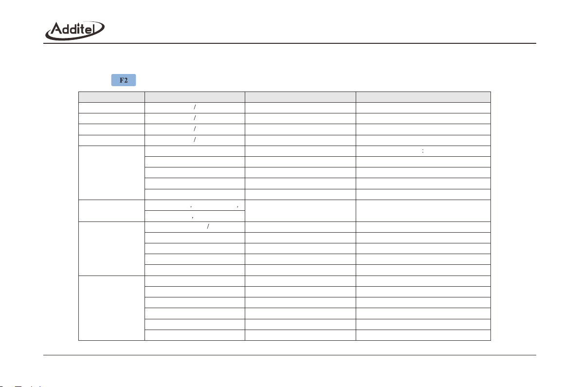
3.2.3 Setup
1. Paramete rs
◆ Press to setu p the followi ng functions.
Category
MFR (Manufacturer)
Model
Device id
Tag
Device Info
Revision
Sensor
Signal
Sub Category
N A
N A
N A
N A
Address
Date
Descriptor
Message
Write Protect
Hart Revision No req preams
Software rev Hardware rev
PV Snsr s r
PV Snsr Unit
PV LSL
PVUSL
PV Min Span
PV Unit
PV LRV
PV URV
Damping
Xfer Fcn
AO Alarm Type
Read Only or Read and Write
Table 3-3 HART setup
22
Read only
Read only
Read only
Read and write
Read and write
Read and write
Read and write
Read and write
Read only
Read only
Read only
Read only
Read only
Read only
Read only
Read and write
Read and write
Read and write
Read and write
Read and write
Read only
Description
Transmitter manufacturer
Manufacturer model number
Manufacturer device id
Enter an alphanumeric tag. (8 max length)
Polling address Interger (0~15)
Any accepted date
Enter an alphanumeric tag. (16 max length)
Enter an alphanumeric tag. (32 max length)
Manufacturer setting
Manufacturer revision settings
Manufacturer setting
Sensor pressure unit
Process variable lower limit
Process variable upper limit
Process variable span
Process variable pressure unit
Process variable lower limit
Process variable upper limit
Numeric entry (0~199) seconds
Selectable (Linear or Square Root)
Manufacturer setting for alarm state
Page 30
2. Operations
◆ Press / to view the HART parameters, and press / to open the setting status.
◆ In the setting status press / to select and press / to set.
◆ If the operation is canceled or fails, the value of the parameter will be reset.
3.2.4 Service
1. Loop test
◆ Select the predefined value or manually input a value, the range is (4~20) mA, and press / to test. The
ADT761 will then provide a mA source to the transmitter of the selected value. It will then read back the loop in real
time next to the term Loop mA.
◆ The Loop test is not available when the HART device is in multi-drop mode. All Field Devices must be able to operate
in multi-drop with loop current signaling disabled according to the HART Protocol.
2. D/A output trim
◆ Through adjusting the coefficient of current output, the transmitter`s PVAO is consistent with loop mA.
◆ Press / to trim the Zero (DAC Zero) and Span (DAC Gain), or press to put the mA value
measured by calibrator into the Trim Value input box. The range is (4~20) mA.
◆ The trim is not available when the hart device is in multi-drop mode. All Field Devices must be able to operate in
multi-drop with loop current signaling disabled according to the HART Protocol.
3. Zero trim
◆ Reduce the measure to near zero to avoid failure.
4. Re-Range
◆ Support to change the PV/Range unit and pressurize mode (internal pressure source or external pressure source).
◆ Test the pressure transmitter and change the range to adjust the shift of the output current.
◆ Press / to change the LRV/URV, or press to put the PV value into the New LRV/URV input box.
5. Sensor Trim
23
Page 31
◆ Some transmitters do not support the sensor trim function.
◆ A Sensor Trim can involve one or more trim points according to different transmitters.
◆ Support to change the PV unit and pressurize mode (Internal pressure source or External pressure source).
◆ The trim points in the internal pressure source mode cannot exceed the control range of the Control Setup, or the
calibrator will prompt the user to reset limits.
◆ Press / to trim point, or press to put the pressure value sourced by calibrator into the Trim
Value input box.
3.3 Typical applications in the main screen
3.3.1 Calibrating pressure gauges
1. Prepare
◆ Select High range or Low range in SOURCE mode.
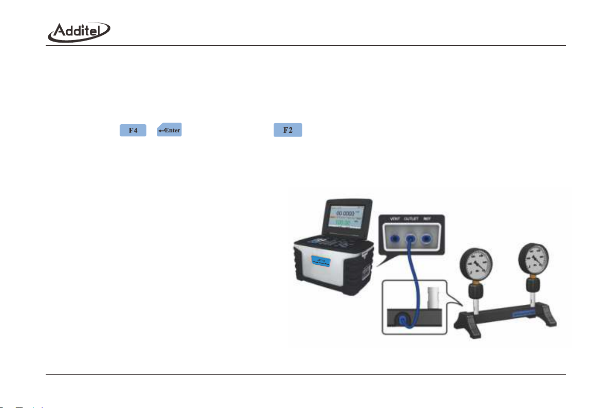
2. Connect
◆ Complete the pneumatic connection as
/FLT
shown in Figure 3-16.
◆ For low range differential sensors, connect the
REF/FLT port to the reference port of the gauge
as shown in Figure3-4.
3. Pressurize manually or by the Step function
(Section 3. 1.11).
4. Record indicator reading of UUT manually after
the pressure has stabilized.
3.3.2 Calibrating pressure transmitters
Figure 3-16 Calibrating pressure gauges
1. Prepare
24
Page 32
Select the High or Low range in SOURCE mode.
◆ Select the Current or Voltage in MEASURE mode.
◆ Activate 24V power.
2. Connect
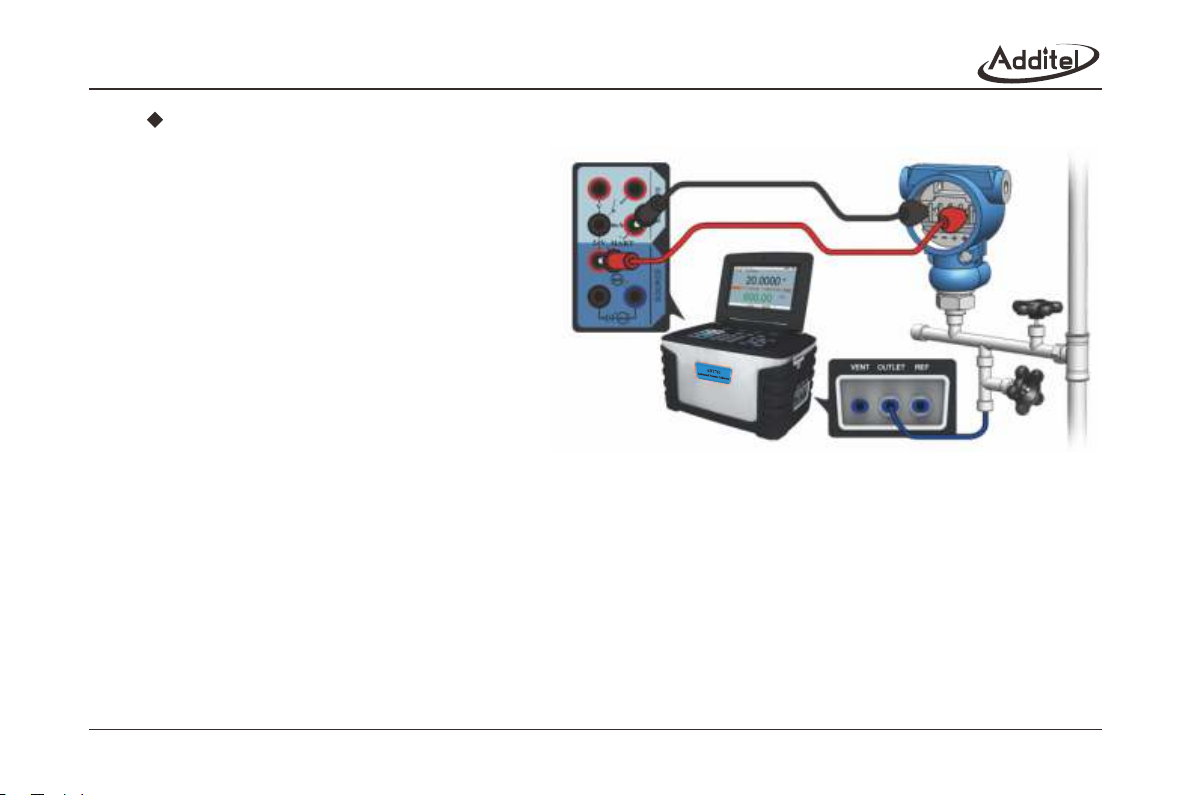
◆ Complete the pneumatic connection as
shown in Figure 3-17.
◆ For low range differential sensors, connect the
REF/FLT port to the reference port of the gauge
as shown in Figure3-4.
3. Pressurize manually or by the step function
/FLT
(Section 3.1.11).
4. Record the measure value manually or by using
snapshot (Section 3.1.12) after the pressure has stabilized.
Figure 3-17 Calibrating a pressure transmitter
3.3.3 Calibrating HART transmitters
1. Prepare
◆ Select the High or Low range in SOURCE mode.
◆ Select the current in MEASURE mode.
◆ Activate 24V power.
2. Connect
◆ Complete the pneumatic and the electrical connections as shown in Figure 3-13 and Figure 3-17, when using
internal series resistor and 24V loop power.
25
Page 33
3. Press to initiate communication with the HART transmitter (Section 3.2.1), and press to change the
process variable to HART-AO (Section 3.2.2).
4. Press to set the parameters of the HART transmitter (Section 3.2.3).
5. Press to service the HART transmitter (Section 3.2.4).
6. Pressurize manually or by the step function (Section 3.1.11).
7. Record the measured value or by using snapshot (Section 3.1.12) after the pressure is stabilized (include 4
process variables).
3.3.4 Calibrating pressure switches
1. Prepare
◆ Select the High or Low range in SOURCE mode.
◆ Select the Switch in MEASURE mode.
2. Connect
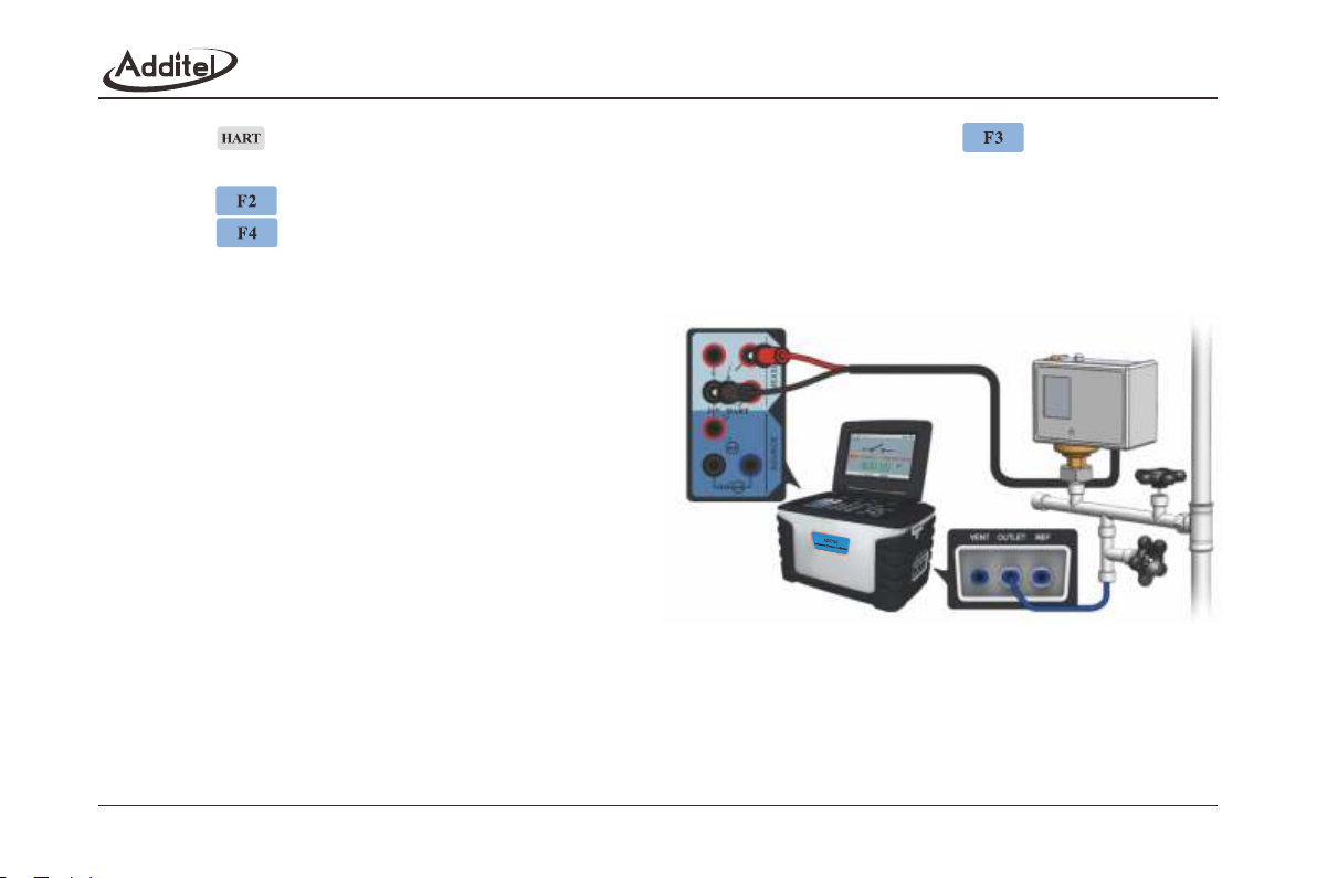
◆ Complete the pneumatic and electrical connection
as shown in Figure 3-18.
/FLT
3. Capture trip values
◆ Automatic:
1) Pressurize to the high limit of the UUT until the switch trips.
Figure 3-18 Calibrating a pressure switch
2) Decompress to the low limit of the UUT until the switch trips.
3) To capture a more precise switch point, the Slew Rate should be set to low speed in the Control Setup screen.
◆ Manually:
1) Pressurize to the anticipated trip point of the switch.
26
Page 34
4. Record the trip values manually or by using snap shot (Section 3.1.12)
3.3.5 Calibrating I/P converters
1. Prepare
◆ Select Current in SOURCE mode.
◆ Select the High or Low range in MEASURE mode.
◆ An external pressure module may be used to measure
the process pressure.
2. Connect
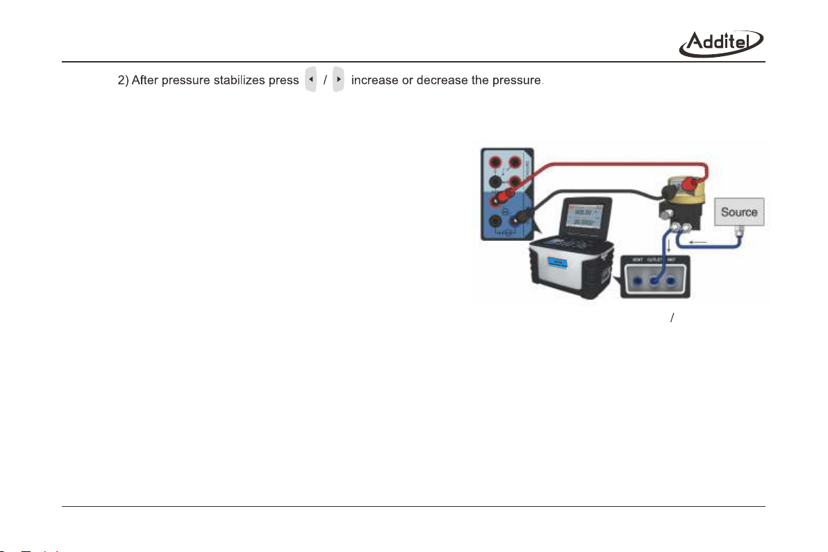
◆ Complete the pneumatic and electrical connections as shown
/FLT
in Figure 3-19.
◆ DO NOT over pressure the calibrator.
◆ DO NOT use the calibrator as the pressure source.
Figure 3-19 Calibrating a I P converter
◆ Check the load ability of the UUT for using the internal 24V power supply.
3. Source the current manually or by the step function (Section 3.1.11).
4. Record the measured value manually or by using snapshot (Section 3.1.12) when the pressure has stabilized.
3.3.6 Calibrating isolator/convert/signal-acquiring devices
1. Prepare
◆ Select the Current in SOURCE mode.
◆ Select the Current or Voltage in MEASURE mode.
27
Page 35

2. Connect
◆ Complete the electrical connection as per the requirement of the UUT.
3. Source the current manually or by the step function (Section 3.1.11).
4. Record the measured value manually or by using snapshot (Section 3.1.12) when the measurement stabilizes.
3.4 Setup
◆ Press to enter the Setup screen which contains 12 options. Press and / to select.
◆ Any changes to the settings will become the default when the unit is powered on.
3.4.1 Control setup
1. P. Form (Pressure type)
◆ Two types: G-Gauge and A-Absolute. The ADT761-LLP and ADT761-D have no control type selection)
◆ The symbol of the pressure type will be shown on the status bar in the home screen.
2. Ctrl LRV and Ctrl URV (Control limits)
◆ A range smaller than the calibrator range may be selected to limit the output pressure to avoid over pressurizing
sensitive UUTs.
◆ The set point of the controller cannot exceed this range, or the calibrator will prompt the user to reset the limits.
◆ Ctrl LRV is the lower limit and Ctrl URV is the upper limit.
3. Stability Criteria
◆ Ctrl Stability (Control stability): the stability requirement in %FS which determines the set point stability which
changes the measured value from black to green based on the delay time. The range is (0.005~10) %FS.
◆ Stable delay: the stability time determined after the calibrator has achieved the set point.
◆ The calibrator is considered stable in the following conditions.
28
Page 36
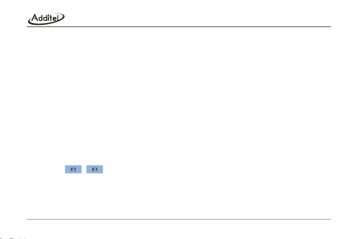
1) (Output value-Set value) <= control stability setting.
2) Control stability is achieved within the stable delay period.
◆ Stable beep: the stable prompt sound.
4. Slew rate
◆ Pressurize at a fast/medium/slow speed.
◆ The default is fast but may be changed to better determine the precise trip value when testing a pressure switch.
5. Switch damping
◆ Averaging time period before the switch trips. The range of the time is (0.1~99) seconds and the default is 0.1.
◆ Set it according to the switch specifications, too long of a dampening time may cause an error in the trip point.
6. Auto Zero
◆ If enabled, the calibrator will automatically zero pressure value when it is in vent state and record the offset.
◆ If Absolute pressure type selected, the Auto Zero will be disabled automatically.
7. Vent P. (Vent Pressure)
◆ When the real pressure is less than the Vent Pressure setting and when controlling the zero pressure, the calibrator
will automatically vent.
◆ Accepted range of Vent P.: (0~105) %FS.
3.4.2 24V power
◆ Short current protected, then the symbol indicating 24V status on the status bar will flicker.
◆ The DC24V power will stay activated when using the current Source or the HART function with internal loop power and
will return to the original status after the loop power is changed.
3.4.3 Display setup
1. Resolution
29
Page 37
◆ Set the resolution of data display in MEASURE mode or in SOURCE mode.
◆ Viewing the snapshot files, the data display according to the resolution when stored (Section 3.1.12).
◆ In the Task Report, the date displays according to the resolution when the task was created (Section3.5).
◆ If there is a display error, it will display according to six digits.
2. Triple display
◆ If enabled, the home screen will show three windows when the pressure module is connected (Figure 3-2).
◆ If the pressure module is selected as MEASURE or SOURCE, then triple display will appear.
3. Backlight Auto Off (Turn Off Light)
◆ Automatically turns off the backlight after a set time.
◆ Accepted timeout period: Never, 5 minutes, 10 minutes, 30 minutes, 1 hour, 2 hours, and 4 hours.
◆ The backlight will come on by pressing any key.
◆ The backlight is disabled in the Step function and the Control mode.
4. Power Auto Off (Auto Power Down)
◆ Automatically turns off the power after a set time.
◆ Accepted timeout period: Never, 30 minutes, 1 hour and 2 hours.
◆ It is disabled in the Step function, the Control mode and the charging status.
5. Brightness
◆ Press / to increase or decrease the brightness.
◆ Accepted eleven levels.
3.4.4 Date and time
◆ The date and time are shown on the status bar according to the configuration.
◆ The date can be set from 2000-01-01 to 2099-12-31, and the range of time is from 00:00:00 to 23:59:59.
◆ The setting also takes into account the number of days in the month, and leap year.
30
Page 38
3.4.5 Language
◆ Standard: English, Spanish, Simplified Chinese, German, French, Italian, Portuguese.
◆ Optional: Traditional Chinese, Japanese or Russian available upon request.
3.4.6 Factory default
◆ Restore instrument settings to factory default including the Control Setup, the Display Setup and the RS232 Setup. It
also deletes all the snapshots and task files.
◆ The password is 811.
◆ Please note that all new settings will be erased.
3.4.7 Tools
3.4.7.1 Leak test
1. Range Selection
◆ Hi. Range/Lo. Range: Select the internal high/low range for pressurizing to the leak test point automatically with the
calibrator.
◆ P. Module: pressurize with an external pressure source and measure the real pressure with an external pressure
module.
2. Setup
◆ Select the leak test under the tools icon in the setup screen.
◆ Leak test with the internal ranges or the external pressure module.
1) The set point and the wait time do not have to be set with the external pressure module.
2)The pressure unit can be selected. The default unit is kPa. (Section 3.1.4).
◆The pressure unit will return to the previous selected unit for pressurization (Section 3.1.4).
◆Set point
1) Do not exceed the range of the UUT.
2)With the numerical key pad enter the leak test point.
31
Page 39
◆Wait time: Stabilization time at the set point. After this countdown is finished the test will begin.
◆Test time: After the wait time is finished, the calibrator will stop control and be in standby mode. During the test time
the calibrator will monitor the drop from the start pressure (Start P.) to the ending pressure (End P.) and the change
in pressure or leakage is determined.
3. Run
◆Internal high/low range
1) Press / to start to pressurize to the set point and wait for the displayed pressure to stabilize.
2) The 761 will continue to control and the wait time will count down.
3) When the wait time reaches zero, the calibrator changes to the Standby mode and records the displayed
pressure as the start pressure.
4) The test time will count down, Real leakage = Start pressure - Real pressure.
5) When the test time reaches zero, the calibrator records the displayed pressure as the end pressure, and then
reduce the system pressure to near the atmospheric pressure.
6) Finally Leakage = Start pressure - End pressure.
7) By pressing the / to pause or continue during step 1), 2), 3), 4), the run mode will be changed
between the Standby and Control in step 1), 2).
◆External pressure source
1) Connect to an external pressure module.
2) Pressurize to the leak test point with an external pressure source.
3) Press / to start to run and record the displayed pressure as the start pressure.
4) Start test and the test time will count down, Real Leakage = Start pressure - real pressure.
5) When the test time reaches zero, record the displayed pressure as the end pressure.
6) Final leakage = Start pressure - End pressure.
32
Page 40
◆A graph is shown depicting each step of the test.
◆Press to vent and end the test.
◆The set point with the internal ranges cannot exceed the control range of the Control Setup, or the calibrator will
prompt the user to reset the limits.
3.4.7.2 Vent
This operation will clean out impurities from the calibrator by pressurizing the calibrator and venting the system.
1. Connect
◆Plug the Outlet port with the provided plug.
◆Please gather and properly dispose of any pollutants during venting as shown in Figure 3.20.
◆The vent port should not face the operator.
2. Run
◆Select vent under the tools icon in the setup screen.
◆The 761 will automatically switch to the high range.
◆Press / to pressurize to the venting pressure (Set Point).
◆When the pressure reaches the venting pressure, the vent valve will open to release the system gas and other
pollutants.
◆Venting can be performed repeatedly.
◆The set point cannot exceed the control range of the Control Setup, or the calibrator will prompt the user to reset the
limits.
3.4.7.3 Unit conversion
◆Select converter under the tools icon in the setup screen.
◆Eleven pressure units are show in the conversion chart.
33
Page 41

◆Entering an y value with the nu meric key pad w ill show the co rresponding v alues in all un its.
3.4.7.4 Hel p
The calib rator provi des images and di agrams show ing basic conne ctions and ty pical appli cations.
◆Selec t the Help in the set up screen.
◆Press / t o view.
3.4.8 Infor mation
◆Sys Inf o: Model, seria l number, soft ware rev, ha rdware rev, and manufac turing date.
◆Atmos .: Provides the a tmospheri c pressure.
◆Hi and lo w Range: Model, r ange, overl oad, manufact uring date, s erial numbe r, form (pressur e type), accu racy, and
software re v.
◆P. Mo dule: If an ext ernal pressur e module is con nected, the m odel, range, ov erload, and m anufacturin g date
informati on is displayed .
3.4.9 Syste m Calibration
◆The calibra tor should be pow ered to warm up 3 0 minutes prior t o starting th e calibrati on.
◆To ensu re optimum inst rument oper ation, the cu rrent/volta ge measure, t he current sour ce and the inte rnal dual
pressure ra nge should be cal ibrated at re gular interva ls.
◆The cal ibrator also pr ovides a way to c alibrate the ex ternal ADT16 0 pressure mo dule.
◆The cal ibrator can als o calibrate i nlet pressure a nd atmosphe re pressure .
◆Makin g errors when cal ibrating wi ll affect t he precision an d possibly ev en cause abno rmalities.
◆The cal ibration data c an be restore d to the factory de fault, and th e calibrati on date changes t o “----/--/ --”.
◆Recom mend the use of app ropriatel y accurate prim ary standar ds when calib rating this ins trument.
◆Enter t he system calib ration in the S etup screen and s elect the fun ction.
◆The pas sword is 811.
34
Page 42
3.4.9.1 Current/voltage measure
1. Calibration points
◆The default is -30mA, 0mA, 30mA for current measure and -30V, 0V, 30V for voltage measure.
◆Calibration points can be edited with the respective range as follows if needed:
1) (-30~-18)mA or (-30~-18)V for negative full scale.
2) (-12~12)mA or (-12~12)V for zero.
3) (18~30)mA or (18~30)V for positive full scale.
2. Run
◆Press / to start.
◆According to the calibration point prompt by the calibrator, use a more precise, higher-standardized unit generates
signal to the calibrator.
◆When the measured value is stable, Press / to record and continue, press / to review.
3.4.9.2 Current source
1. Calibration points
◆The default is 4mA, 20mA that cannot be edited.
2. Run
◆Press / to start.
◆The calibrator will provide the current to a standard ampere-meter on schedule. When the reading is stable, input
the reading into the calibrator.
◆Press / to record and continue and press / to review.
◆The accepted range of the standard gauge is (0 ~ 30)mA.
3.4.9.3 High/low range
1. Calibration points
◆If the range is mixed, execute in three-point mode calibration with the low limit, the zero and the high limit as default.
35
Page 43
3) Press / to record and continue and press / to review.
◆Once user calibration is completed, the system date will be recorded by the date of calibration.
3.4.9.4 External pressure module
1. Calibration points (as shown in Section 3.7.3-1).
2. Run
◆Connect the external pressure module.
◆Press / to start.
◆Use a standard pressure source to pressurize the pressure module and wait for the measured value to stabilize.
◆Press / to record and continue, and press / to review.
3.4.9.5 Self tune
For factory test only.
3.4.10 RS232 setup
◆Select the RS232 setup in the setup screen.
◆Set the baudrate, databits and stopbits.
◆Press numeric keypad to set the address, and the range is 001~121.
3.5 Task
The calibrator provides the task function for automated calibration while storing and archiving the calibration
data. To use this function, press and it provides five kinds of calibration task for the following UUTs: dial pressure
gauge, digital pressure gauge, pressure transmitter, pressure switch and I/P converter. When using different types of
equipment the MEASURE and SOURCE will be set automatically. The maximum number of tasks stored is 200.
◆ When the cursor is on New Task, press to delete all the tasks and data. Carefully select your operation as they
cannot be reversed.
36
Page 44
◆ When the cursor is on New Task, press / to create a new task with the last one as a template.
◆ Press / to select a task and view its information, and press / to page up and down.
◆ Press to save as a new task.
◆ Press to delete the selected task and its data. Carefully select your operation as it cannot be reversed.
◆ If the selected task calibration has not been ran, press / to show the run information screen.
◆ If the selected task has been ran, press / to view the report.
◆ The task can be repeated, but only the last result will be recorded. Carefully select your operation as they cannot be
reversed.
◆ View the run information and report. The failures are
red and “--------”stands for no record.
◆ The data can be uploaded to a computer with RS232
interface cable. And tasks can be generated and
managaged on a PC using Additel/Cal software and
loaded to the calibrator through the RS232 interface.
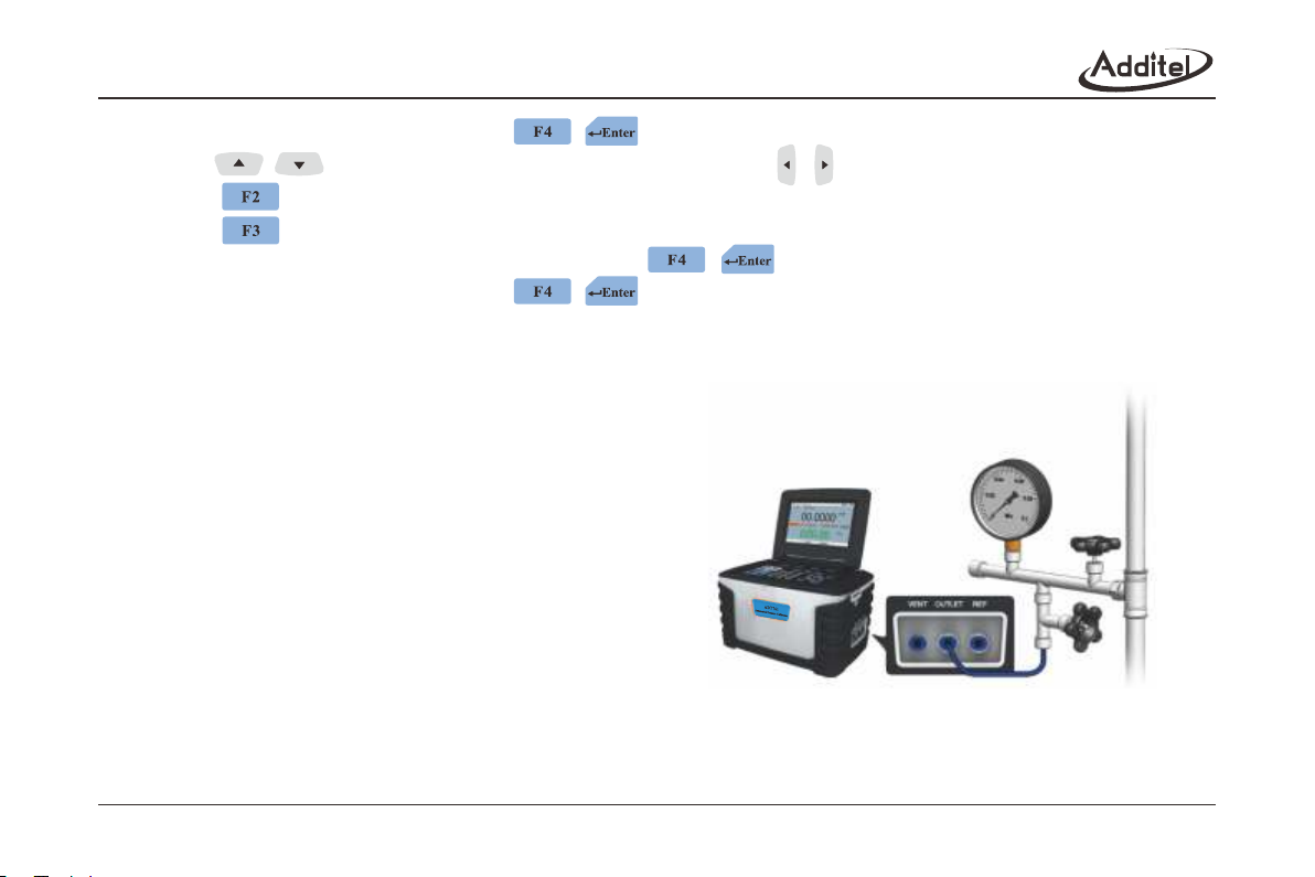
3.5.1 Calibrating dial pressure gauges
1. Connect
/FLT
◆ Connect the calibrator to the dial pressure gauge
as shown in Figure 3-20.
◆ Connect the REF/FLT port to the low pressure port
of the differential pressure gauge.
Figure 3-20 Calibrating a dial pressure gauge
2. New Task
37
Page 45
◆ Task name
1) Enter an alphanumeric name, and press numerical keypad to input special codes.
2) The name cannot be the same as an existing task.
3) The characters of the task name cannot exceed 13 spaces.
◆ Range of UUT
1) Cannot exceed the output range of the calibrator.
2) The high and low limit cannot be equal.
3) The calibrator will automatically select the range for higher precision.
4) The calibrator will use dual range if needed.
5) Over pressuring can result in damage to the UUT.
◆ Pressure type: gauge, absolute or differential.
◆ Accuracy
1) Preselected accuracies are available.
2) Custom X.XX*: When the custom range is selected, press F2, and the field can be edited to the desired accuracy
from (0.01 to 100)%FS.
◆ Calibration points
1) The range is 2 to 17.
2) Scale will default to linear steps over the chosen range of the UUT.
3) Each test point can be edited individually.
4) Setting a point to less than -0.95bar will be adjusted to -0.95bar.
◆ Resolution
1) To format the indicator of the UUT.
38
Page 46
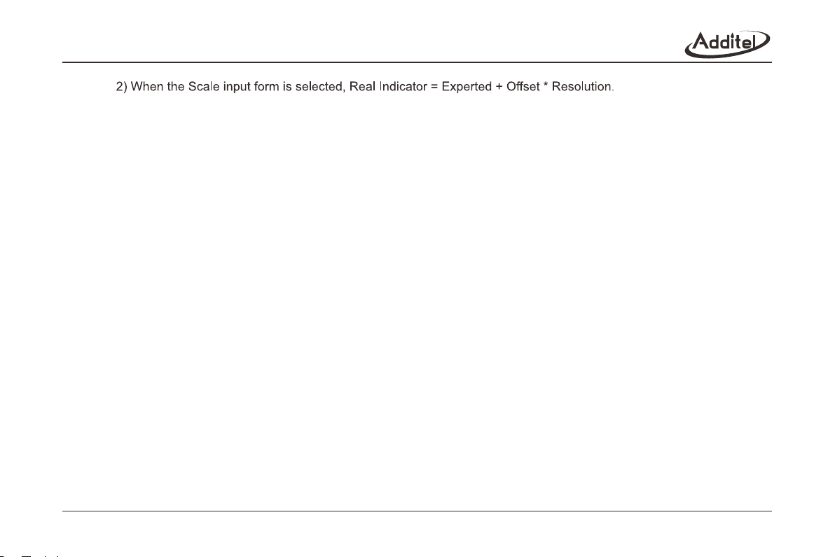
3) Resolution entered in terms of the unit resolution (e.g. resolution of 0.1 when measuring in bar is 0.1 bar).
◆ Tapping: Tap or no tap during the calibration process of the analog gauge.
◆ Cycles: 1 to 3.
3. Run
◆ Input the information before running including the date (the default is the system date), the ambient temperature,
(the default is 25℃ and the range is 0~25℃) and the relative humidity (the default is 40%RH and the range is
0~100%RH).
◆ Pressure Source: Select the Internal Pressure or Pressure Module.
◆ Start and wait for the displayed pressure to stabilize. Input the reading of the UUT that cannot exceed 110%
full-scale of the UUT. When continuing with no input, the standard value will be recorded as the indicator. If
tapping is enabled, the calibrator will ask you to input the reading after tapping the indicator. Complete this
step and continue.
◆ Continue through the remaining pressure set points until finished. You can then generate a calibration report.
◆ When dual range is being used, the calibrator will switch the pressure range automatically.
◆ The calibration points of the task cannot exceed the control range of the Control setup, or the calibrator will
prompt the user to reset the limits.
◆ The calibrator will automatically switch to the suitable range if needed.
39
Page 47
3.5.2 Calibrating digital pressure gauges
1. Connect
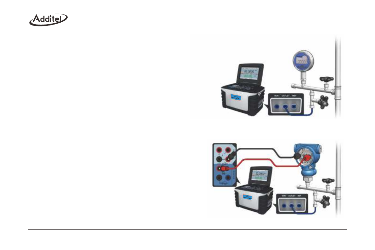
◆ Connect the calibrator to the digital pressure gauge as
shown in Figure 3-21.
◆ When testing a differential pressure gauge use the REF/FLT
port to connect to the low pressure port of the differential
pressure gauge.
2. New and run
The task set up and run is very similar to a dial pressure gauge
(Section 3.5.1) except:
◆ Accuracy settings where the accuracy can be defined as a
% of FS or a % of reading or a combination of %FS and %
of reading.
3.5.3 Calibrating pressure transmitters
When calibrating a pressure transmitter, the calibrator
will measure and record the current/voltage from the
transmitter, supply 24V loop power, at every desired
set point automating the full calibration.
1. Connect
◆ Connect the calibrator to the pressure
transmitter as shown in Figure 3-22.
/FLT
Figure 3-21 Calibrating a digital pressure gauge
/FLT
Figure 3-22 Calibrating a two wire pressure transmitter
40
Page 48
◆ When testing a differential pressure transmitter use the REF/FLT port to connect to the low pressure port of the
differential pressure transmitter.
2. New
◆ Task name
1) Enter an alphanumeric name, and press to input special codes.
2) The name cannot be the same as an existing task.
3) The characters of the input test name cannot exceed 12 spaces.
◆ Range of UUT
1) Cannot exceed the range of the calibrator.
2) The high and low limit cannot be equal.
3) The calibrator will automatically select the range for higher precision.
4) The calibrator will use the dual range if needed.
5) Over pressuring the UUT may result in damage to the UUT.
◆ Pressure type: Gauge, Absolute or Differential.
◆ Accuracy
1) Preselected accuracies are available
2) Custom X.XX*: When the custom range is selected, press F2, and the field can be edited to the desired accuracy
from (0.01 to 100)%FS.
◆ Calibration points
1) The range is 2~17.
2) Scale will default to linear steps over the chosen range of the UUT.
3) Each test point can be edited individually.
4) The points less than -0.95bar will be adjusted to -0.95bar.
41
Page 49
◆ Measure signal
1) Includes six selections of typical pressure transmitters.
2) Calibrate a HART transmitter as seen in Section 3.5.4.
3) Custom mA *(X-XX)mA: the range is (-30~30) mA.
◆ Transfer function
1) Linear: the output and measure are both linear.
2) Square root: The output is linear, but the measure value is square root.
◆ Cycles: 1~3.
3. Run
◆ Input the information before running including the date (the default is the system date), the ambient temperature (the
default is 25℃ and the range is 0~50℃) and the relative humidity (the default is 40%RH and the range is
0~100%RH).
◆ Pressure Source: Internal Pressure or Pressure Module.
◆ Select the run mode
1) Automatic: When the pressure is stable, the calibrator will count down based on the Reading Time in seconds
before taking the measurement and continuing to the next set point.
2) Manual: press / to continue after the pressure has stabilized.
◆ Start and wait for the displayed pressure to stabilize, and then record the measured value. Complete this step and
continue.
◆ The set points are generated automatically and after the test is complete a report is generated automatically.
◆ When dual range is used, the calibrator will switch the pressure range automatically.
◆ The calibration task points cannot exceed the control range of the Control Setup, or the calibrator will prompt the
user to reset the limits.
42
Page 50
◆ The calibrator will automatically switch to the suitable range if needed.
3.5.4 Calibrating HART transmitters
1. Connect
◆ Connect the calibrator to the HART transmitter as shown in Figure 3-13 and Figure 3-22 in the internal series
resistor and internal 24V loop power mode.
2. New
◆ Measure signal:
1) HART.
2) Process variable: HART-PV, HART-AO, HART-%, Loop mA.
◆ Transfer function.
1) Linear: the output and measure are both linear.
2) Square root: when the process variable is AO or loop mA, the output is linear, but the measure is square root.
◆ The other introduction is similar with calibrating a common pressure transmitter (Section 3.5.3).
3. Run
◆ Poll HART devices automatically if needed or press to do it manually (Section 3.2.1).
◆ Compare the range of the task settings with the real range of the HART transmitter.
◆ If the process variable is HART-AO, HART-% or Loop mA, the transfer function of the HART transmitter will be
changed to the same as the transfer function of the task settings.
◆ HART disconnection will cause the task to end.
◆ The other introduction is similar with calibrating a common pressure transmitter (Section 3.5.3).
4. Service
◆ As found data is the task result showing the condition of a HART transmitter before it is calibrated.
◆ Press to trim the HART transmitter (Section 3.2.4).
◆ Press to restart the task after servicing, and the result is recorded as left.
43
Page 51
3.5.5 Calibrating pressure switches
1. Connect
◆ Connect the calibrator to pressure switch as shown in Figure 3-23.
2. New
◆ Task name
1) Enter an alphanumeric name, and press numerical keypad to
input special codes.
2) The name cannot be the same as the existing task.
3) The characters of the input test name cannot exceed 13 spaces.
◆ Pressure type: Gauge, Absolute or Differential.
◆ Range: Pressure range of the switch.
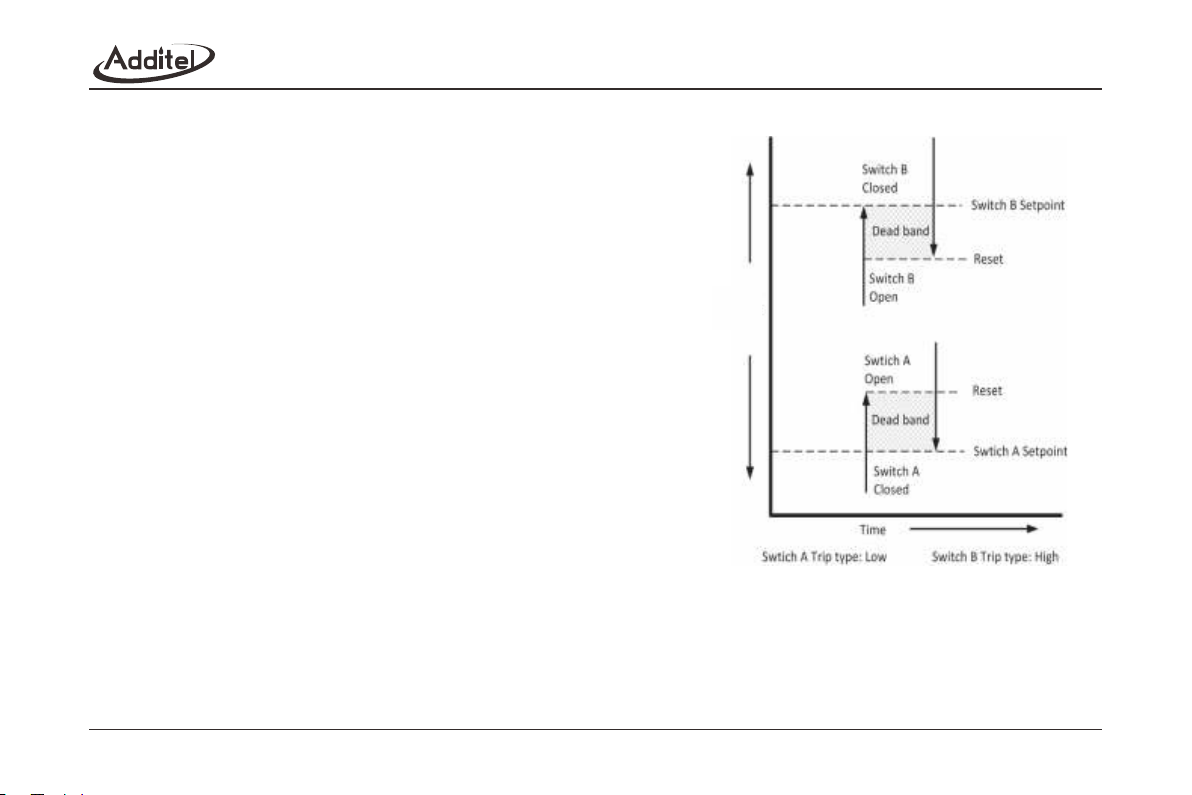
◆ Dead band range: is the minimum and maximum of the dead band,
Dead band is the pressure difference between the change-of-states
(i.e. OPEN-CLOSE or CLOSE-OPEN).
◆ Set point: The pressure which the switch will change state.
◆ Tolerance: The allowable variation from the set point pressure.
◆ Trip type: High or Low. This is the direction to which the
change-of-state should happen. If the trip type is low, this means the
change-of-state happens when the pressure
is falling. If the trip type is high, this means the change-of-state happens when the pressure is rising.
◆ Cycles: 1~3.
Pressure
Figure 3-23 Switch Terminology
44
Page 52
3. Run
◆ Input the information before running including the date (the default is the system date), the ambient temperature (the
default is 25℃ and the range is 0~50℃) and the relative humidity (the default is 40%RH and the range is
0~100%RH).
◆ Pressure Source: Internal Pressure or Pressure Module.
◆ Automatically run the task according to setting.
◆ Record and display the trip values in the table.
◆ Press / to pause and continue the task and the mode will be changed between Standby and Control.
◆ The calibrator will automatically switch to the suitable range if needed.
◆ The calibrator can change the slew rate of the pressure control automatically according to the Setpoint and
Tolerance of the setting, also you can change the slew rate manually by press / .
3.5.6 Calibrating I/P converters
1. Connect
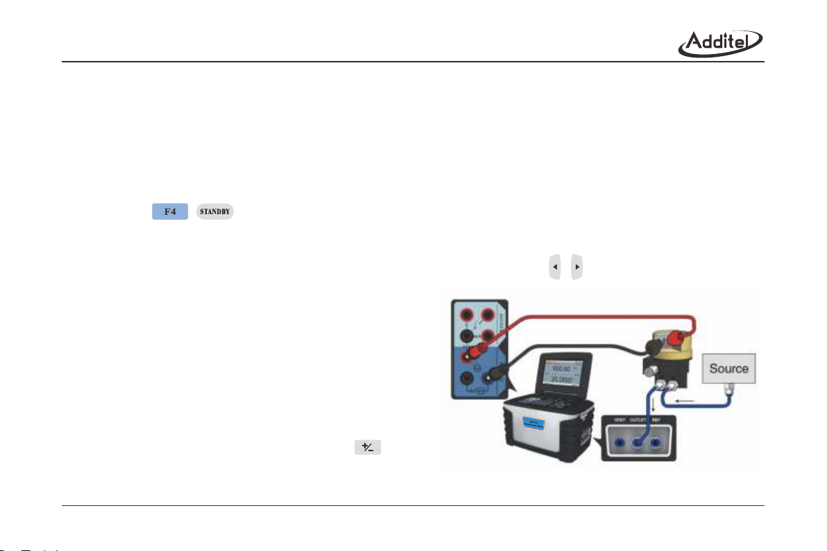
◆ Connect the calibrator to the I/P converter as shown
in Figure 3-24.
◆ Do not over pressure the calibrator.
◆ Check the load ability of the UUT for the internal 24V
power supply.
2. New
/FLT
◆ Task name.
1) Enter an alphanumeric name, and press to input
the special codes.
Figure 3-24 Calibrating an I/P converter
45
Page 53
2) The name cannot be the same as the existing task.
3) The characters of the input test name cannot exceed 13 spaces.
◆ Output signal: According to the current range of the UUT.
◆ Accuracy.
1) Given: 0.05%, 0.1%, 0.15%, 0.25%, 0.5%, 1.0%, 1.6%.
2) Custom *X.XX%: When the custom range is selected, press F2, and the field can be edited to the desired
accuracy from (0.01 to 100)%FS.
◆ Calibration points.
1) The range is 2~17.
2) Scale will default to linear steps over the chosen range of the UUT.
3) Each test point can be edited individually.
◆ Range of UUT.
1) Cannot exceed the measure the range of the calibrator.
2) The high and low limit cannot be equal.
◆ Cycles: 1~3.
3. Run
◆ Input the information before running including the date (the default is the system date), the ambient temperature (the
default is 25℃ and the range is 0~50℃) and the relative humidity (the default is 40%RH and the range is
0~100%RH).
◆ Pressure Source: Internal Pressure or Pressure Module.
◆ Select the run mode.
1) Automatic: Set the wait time and delay time, and their ranges are both 0~3600. When the pressure is stable, the
wait time will count down to zero, then the task will continue to the next set point. When the run direction is ready
46
Page 54

to descend, the delay time will count down to zero, then the task turns to the descending points.
2) Manual: Press / to continue after the pressure is stabilized.
◆ Start and wait for the displayed pressure to stabilize, and then record the measured value. Complete this step and
continue.
◆ Source the current of the set points until the end and generate a report automatically.
◆ Recall the previous steps: press / to pause and the calibrator will switch to the Standby mode, and
then press / to recalibrate this set point.
4. Troubleshooting
4.1 Device information
◆ Select the device information in the setup screen.
◆ View the software revision, factory date, serial number and so on.
◆ View the information of the high / low range inside.
◆ View the current atmospheric pressure.
4.2 Prompt
The display shows a screen prompt warning as follows:
Error message Description
The calibration will be automatically matched to gauge
pressure to match the internal sensor type
Unable to control Please check the system for leaks
As the pressure type of internal pressure sensor is gauge the calibration should
be matched with gauge pressure
Under the condition of system leakage the self tuning function will lead next
steps to errors So the users must check if the plugs is well connected and try
again
47
Page 55
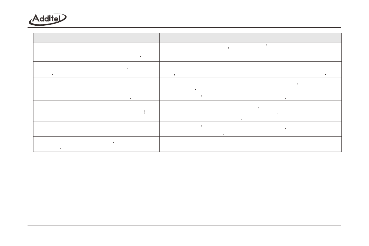
Error message Description
The set pressure value exceeds the maximum pressure
of this device due to your atmospheric pressure
Over protection pressure range exceeded System is
venting
Connecting internal pressure sensor
The internal valve temperature is abnormal
The test sensor for inlet pressure is not calibrated
Self tuning discontinued due to the internal valve
temperature
Unable to find the pressure module Please check the
connection
Under the current atmosphere the set pressure s value is higher than rated
maximum pressure of device The users should check the local atmosphere
factor
While the actual output pressure is out range of RATED overpressure protecting
value the system will automatically run the vent function for self-protection
The system is failing to connect with internal pressure module but it is trying over
and over again
The internal valve s temperature is abnormal or irregular
Before ADT761 generates any set pressure all inlet air pressure will be roughly
tested by a specialized pressure sensor on entrance THIS sensor should be
standardized or calibrated in factory
The internal valve s temperature is abnormal or irregular that will results the
self-tuning function in errors
The system is failed to communicate with the corresponding pressure module
Table 4-1 Prompt and disposal
4.3 Checking system for leaks
4.3.1 Checking for leaks
The calibrator must be leak free in order to function properly. Leakage may lead to control errors. A rapid pressure
drop will indicate a leak in the system. Check potential problems as follows:
◆ Plug the OUTLET port.
◆ Generate a pressure, let it stabilize, and turn to standby mode. Wait for 2 minutes.
48
Page 56
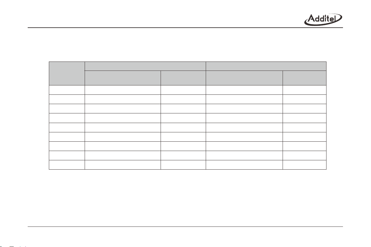
◆ The leak rate should be less than 0.02mbar/s for ADT761-D and 0.2bar/s for ADT761-L and ADT761-M or it is
possible the calibrator has a leak.
◆ The ADT761 can also run an automatic leak test (as shown in Section 3.6.1).
Model
ADT761-LLP
ADT761-D
ADT761-L
ADT761-M
ADT761-H
ADT761-LA
ADT761-MA
ADT761-HA
ADT761-BP
Pressure Module 1
Range Range
-2.5 to 2.5 mbar (-1 to 1 inH2O)
-25 to 25 mbar (-10 to 10 inH2O)
-0.95 to 2.5 bar (-13.5 to 35 psi)
-0.95 to 2.5 bar (-13.5 to 35 psi)
-0.95 to 2.5 bar (-13.5 to 35 psi)
0.05 to 3.5 bar.a (1.2 to 50 psi.a)
0.1 to 3.5 bar.a (1.7 to 50 psi.a)
0.1 to 3.5 bar.a (1.7 to 50 psi.a)
100 to 1200 hPa
Critical leak rate
(mbar/s)
0.01
0.01
0.2
0.2
0.2
0.2
0.2
0.2
0.2
-25 to 25 mbar (-10 to 10 inH2O)
-0.95 to 1 bar (-13.5 to 15 psi)
0 to 7 bar (0 to 100 psi)
0 to 25 bar (0 to 375 psi)
0 to 40 bar (0 to 600 psi)
0.05 to 8 bar.a (1.2 to 115 psi.a)
0.1 to 26 bar.a (1.7 to 390 psi.a)
0.1 to 41 bar.a (1.7 to 615 psi.a)
Pressure Module 2
N/A
Critical leak rate
(mbar/s)
0.01
0.2
0.2
2
2
0.2
2
2
N/A
Table 4-2 The criteria leak rate of the calibrator has a leak
4.4 Instability
If the pressure has been unstable for more than 3 minutes in the CONTROL mode, the calibrator will switch to the
STANDBY mode and check for the following:
◆ Make sure all fittings are tightened (Section 3.4.1).
◆ Investigate the system for any potential leaks.
49
Page 57
5 Special Application for Barometric Pressure
The ADT761-BP is a unique calibrator and different from all the other ADT761 series calibrators.
5.1 ADT761 Basic differences
◆ Single range: 10kPa ~120kPa, absolute sensor type.
◆ Home screen: Does not support the triple display and press to switch to display mode between single window and
two windows.
◆ Zero: This function is not available.
5.2 Gas head correction
◆ If enabled, the calibrator will display the correct result automatically according to the setting of parameters.
◆ Set the Height value in accordance with the Metric or English Units.
◆ Set the Density value in accordance with the Medium (i.e.Nitrogen, Dry Air, etc)
◆ Select standard gravity 980.665 cm/s or the local gravity based on
the calibration location.
5.3 Specific ADT761-BP applications
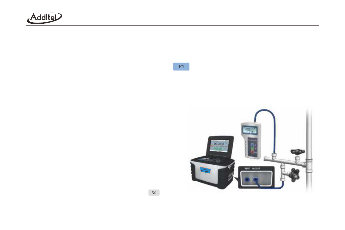
5.3.1 Digital barometer
1. Connect
◆ Connect the calibrator to the digital barometer as
shown in Figure 5-1.
2. New
◆ Task name:
1) Enter an alphanumeric name, and press
to input special codes.
Figure 5-1 Calibrating a digital barometer
50
Page 58
2) The name cannot be the same as the existing task.
3) The characters of the input task name cannot exceed 12 spaces.
◆ Range of UUT:
1) Range: 0.1bar~1.2bar.
2) Cannot exceed the output range of the calibrator.
3) The high and low limit cannot be equal.
4) Over pressurizing will result in damage to the UUT.
◆ Calibration points:
1) The range is 2-17.
2) Scale the steps in accordance with the linear the UUT for the default.
3) Every point can be edited.
◆ Tolerance:
1) Given: ±(0.1, 0.2, 0.3, 0.4, 0.5, 1, 2, 5)mbar.
2) Custom: the custom range is (0-110)mbar.
◆ Resolution.
Given: 1, 0.1, 0.01, 0.001.
◆ Cycles: 1~3, and the default is 2.
3. Run
◆ Input the information before running including the date (the default is the system date), the ambient temperature (the
default is 25℃ and the range is 0~50℃) and the relative humidity (the default is 40%RH and the range is
0~100%RH).
51
Page 59
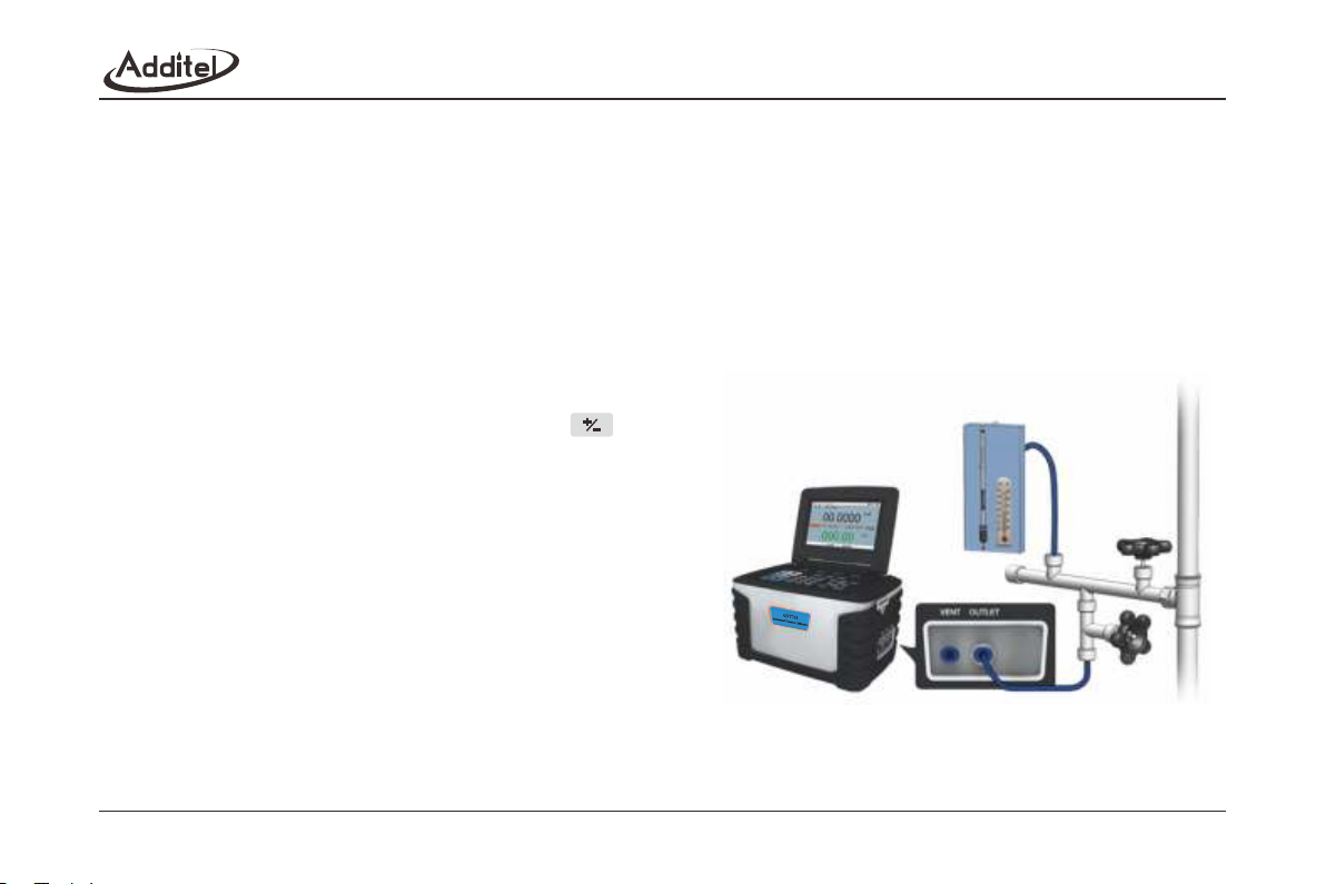
◆ Stroke mode: One Way or Two Way.
◆ Wait for the displayed pressure to stabilize. Input the value from the UUT. After inputting the value for the UUT, the
standard value will be recorded from the calibrator.
◆ After completing all the set points a report is automatically generated.
5.3.2 Mercury barometer
1. Connect
◆ Connect the calibrator to the mercury barometer as shown in Figure 5-2.
◆ Connect the REF/FLT port to the low pressure port of the differential pressure gauge.
2. New
◆ Task name:
1) Enter an alphanumeric name, and press
to input special codes.
2) The name cannot be the same as the existing task.
3) The characters of the input task name cannot
exceed 12 spaces.
◆ Range of UUT:
1) Range: 0.1bar~1.2bar.
2) Cannot exceed the output range of the calibrator.
3) The high and low limit cannot be equal.
4) Over pressuring will result in damage to the UUT.
◆ Calibration points:
1) The range is 2-17.
Figure 5-2 Calibrating a mercurial barometer
52
Page 60
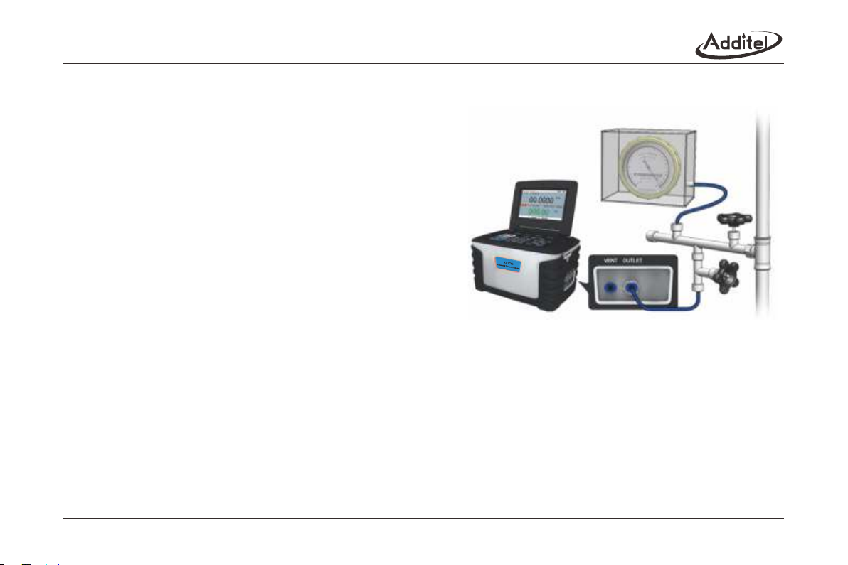
2) Scale the steps in accordance with the linear theUUT for the default.
3) Every point value and tolerance can be edited.
◆ Resolution.
Given: 1, 0.1, 0.01, 0.001.
◆ Cycles: 1~3.
◆ Temperature coefficient: used to correct the value where
applicable.
3. Run
◆ Input the information before running including the date
(the default is the system date), the ambient temperature
(the default is 25℃ and the range is 0~50℃) and the
relative humidity (the default is 40%RH and the range is
0~100%RH).
◆ Stroke mode: One Way or Two Way.
◆ Wait for the displayed pressure to stabilize.
◆ Input the value from the UUT. After inputting the value for the UUT, the standard value will be recorded from the
calibrator.
◆ After completing all the set points a report is automatically generated.
5.3.3 Aneroid barometer
1. Connect
◆ Connect the calibrator to the aneroid barometer as shown in Figure 5-3.
2. New and Run
Creating and running the task are similar with calibrating a mercurial barometer (Section 5.3.2).
Figure 5-3 Calibrating an aneroid barometer
53
Page 61
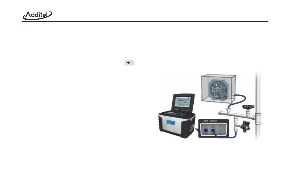
5.3.4 Barometer altimeter
1. Connect
◆ Connect the calibrator to the barometer altimeter as shown in Figure 5-4.
2. New
◆ Task name:
1) Enter an alphanumeric name, and press
to input special codes.
2) The name cannot be the same as the existing task.
3) The characters of the input task name cannot exceed
12 spaces.
◆ Range of UUT:
1) Range: 0.1bar~1.2bar.
2) Cannot exceed the output range of the calibrator.
3) The high and low limit cannot be equal.
4) Over pressuring will result in damage to the UUT.
◆ Calibration points:
1) The range is 2-17.
2) Scale the steps in accordance with the UUT.
3) Every point value and tolerance can be edited.
Figure 5-4 Calibrating a barometer altimeter
54
Page 62
◆ Resolution: the value is 1, 0.1, 0.01, 0.001, and the default is 0.1.
◆ Cycles: 1~3.
3. Run
◆ Input the information before running including the date (the default is the system date), the ambient temperature (the
default is 25℃ and the range is 0~50℃) and the relative humidity (the default is 40%RH and the range is
0~100%RH).
◆ Stroke mode: One Way or Round Trip.
◆ Wait for the displayed pressure to stabilize.
◆ Input the value from the UUT. After inputting the value for the UUT, the standard value will be recorded from the
calibrator.
◆ After completing all the set points a report is automatically generated.
5.3.5 Pressure transmitter
As shown in section 3.5.3 and section 3.5.4.
5.3.6 Pressure switch
As shown in section 3.5.5.
55
Page 63
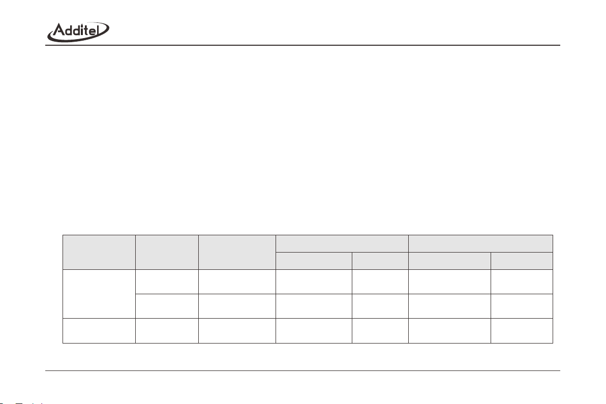
Appendix A Data Sheet
A.1 Environment
◆ Operating temperature: (0~50)℃.
◆ Storage temperature: (-20~60)℃.
◆ Humidity: < 90%RH, non-condensing.
◆ Atmospheric pressure: (0.86~1.06) bar.
A.2 Power
◆ Power: internal rechargeable battery or adapter.
◆ Charging time: less than 3 hours.
◆ Battery operation: typical 8 hours depending on the pressurizing frequency.
A.3 Technical specifications
◆ Internal pressure ranges and accuracy.
Low/Differential
Gauge Pressure
56
Type
Pressure
Model
ADT761-LL P
ADT761-D
ADT761-L
Pressure Range
-25 to 25 mbar
(-10 to 10 inH 2O)
-0.95 to 1 bar
(-13.5 to 15 psi)
-0.95 to 7 bar
(-13.5 to 100 psi)
Table A-1 Pressure ranges
Pressure Module 1
Range
-2.5 to 2.5 mbar
(-1 to 1 inH 2O)
-25 to 25 mbar
(-10 to 10 inH 2O)
-0.95 to 2.5 bar
(-13.5 to 35 psi)
Pressure Module 2
Accuracy Range
0.05%FS
0.05%FS
0.02%FS
-25 to 25 mbar
(-10 to 10 inH 2O)
-0.95 to 1 bar
(-13.5 to 15 psi)
0 to 7 bar
(0 to 100 psi)
Accuracy
0.05%FS
0.02%FS
0.02%FS
Page 64

Type
Gauge Pressure
Gauge/Absolute
Pressure
Barometric
pressure
Model
ADT761-M
ADT761-H
ADT761-LA
ADT761-MA
ADT761-HA
ADT761-BP
Pressure Range
-0.90 to 25 bar
(-13 to 375 psi)
-0.90 to 40 bar
(-13 to 600 psi)
-0.95 to 7 bar
(-13.5 to 100 psi)
0.05 to 8 ba r.a
(1.2 to 115 psi.a)
-0.90 to 25 bar
(-13 to 375 psi)
0.1 to 26 ba r.a
(1.7 to 390 psi.a)
-0.90 to 40 bar
(-13 to 600 psi)
0.1 to 41 ba r.a
(1.7 to 615 psi.a)
100 to 1,200 hPa
Pressure Module 1
Range
-0.9 to 2.5 bar
(-13 to 35 psi)
-0.9 to 2.5 bar
(-13 to 35 psi)
-0.95 to 2.5 bar
(-13.5 to 35 psi)
0.05 to 3.5 ba r.a
(1.2 to 50 psi.a)
-0.9 to 2.5 bar
(-13 to 35 psi)
0.1 to 3.5 ba r.a
(1.7 to 50 psi.a)
-0.9 to 2.5 bar
(-13 to 35 psi)
0.1 to 3.5 ba r.a
(1.7 to 50 psi.a)
100 to 1,200 hPa
Table A-1 Pressure ranges
Note 1: One year accuracy (including yearly stability).
Note 2: Barometric reference: Range(700~1100)hPa, Accuracy0.5hPa.
Pressure Module 2
Accuracy Range
0.02%FS
0.02%FS
0.02%FS
0.03%FS
0.02%FS
0.03%FS
0.02%FS
0.03%FS
0.01%FS
0 to 25 bar
(0 to 375 psi)
0 to 40 bar
(0 to 600 psi)
-0.95 to 7 bar
(-13.5 to 100 psi)
0.05 to 8 ba r.a
(1.2 to 115 psi.a)
-0.9 to 25 bar
(-13 to 375 psi)
0.1 to 26 ba r.a
(1.7 to 390 psi.a)
-0.9 to 40 bar
(-13 to 600 psi)
0.1 to 41 ba r.a
(1.7 to 615 psi.a)
N/A
Accuracy
0.02%FS
0.02%FS
0.02%FS
0.025%FS
0.02%FS
0.025%FS
0.02%FS
0.025%FS
N/A
57
Page 65
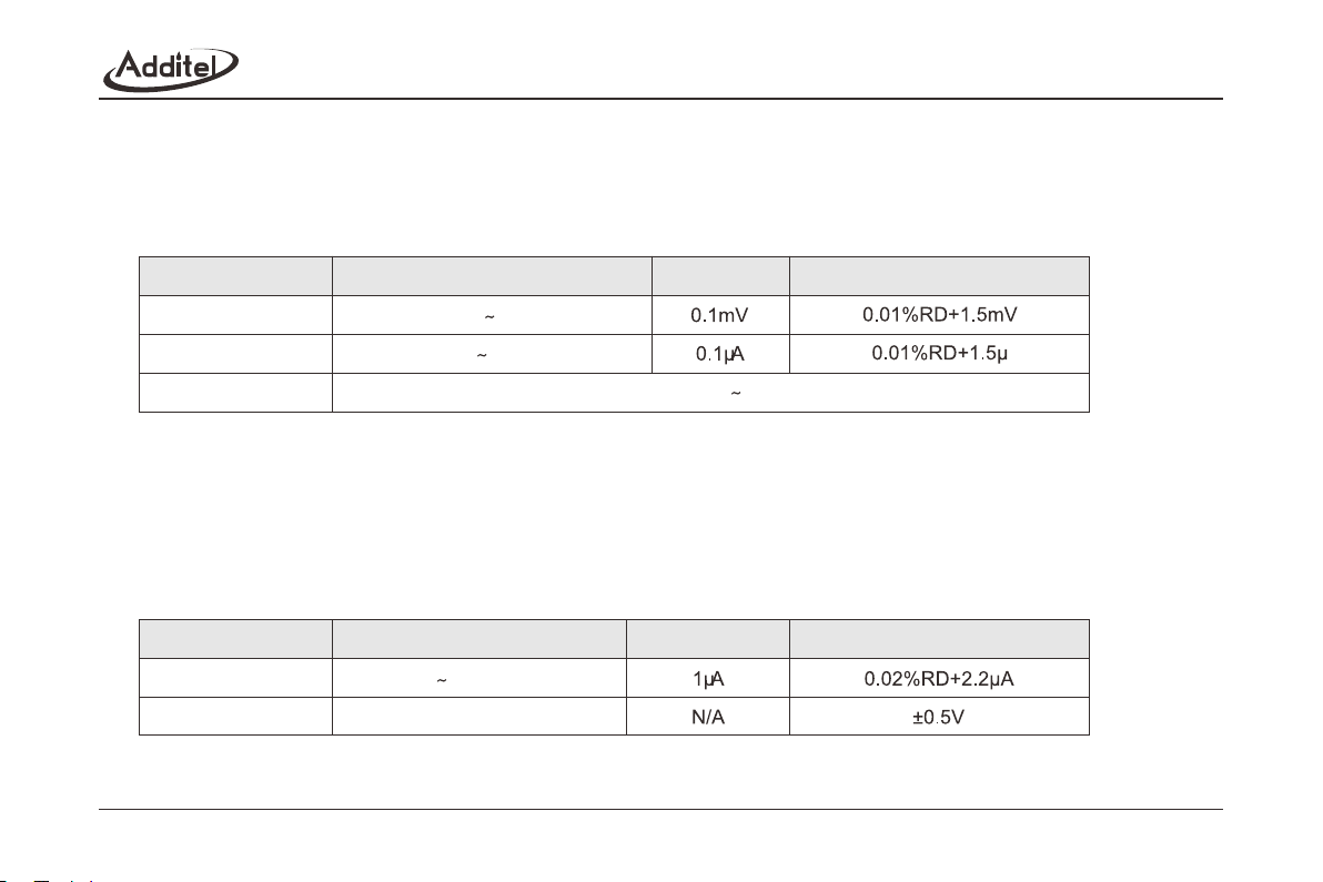
◆ Control stability: 0.005%FS.
◆ Response time: < 30sec. (regarding a 20% press, increase in a 50cc test volume in high speed mode).
◆ Pressure media: clean dry non-corrosive gases.
◆ Electrical measurements (ambient temperature 20℃±5℃, 1 year accuracy).
Signal
Voltage
Range
(-30.0000 30.0000)V
Resolution
Accuracy
Current
Switch
Note 1: temperature coefficient < ±0.0015% RDG / ℃ outside of (15~25)℃.
Note 2: input features:
1) Voltage measurement: input impedance > 1MΩ. Max input voltage is±300V DC.
2) Current measurement: input impedance < 10Ω. Max input current is±1A DC.
◆ Electrical source (ambient temperature 20℃±5℃, 1 year accuracy).
Signal
Current
Loop supply
(-30.0000 30.0000)mA
Test voltage DC 3V DC 24V
Table A-2 Electrical measurements
Range
(0 22.000)mA
24V
Table A-3 Electrical source
Resolution
Accuracy
58
Page 66
Note 1: temperature coefficient < ±0.0015% RDG / ℃ outside of (15~25)℃.
Note 2: input features:
1) Current source: in the internal power mode maximum load current is 20mA@1kΩ. In the external power mode
(0~36V) the peak load meets: output current * load resistance < (voltage -4)V.
2) Short circuit protected.
◆ Display: 7.0" 800×480 pixels color LCD.
◆ Dimensions and weight: 296 (w) * 186(h) * 180(d) mm, and approx. 5.6kg.
◆ Electrical interface: Φ4mm electrical jack.
◆ Charging interface: 2 pin aviation connector.
◆ RS-232 interface: RS-232-DB9 female.
◆ Pressure module interface: 5 pin aviation connector.
◆ Compatible with Additel/Land software which is available for a free download at http://www.additel.com/products/Software/.
59
Page 67

Additel Corporation
2900 Saturn St #B
Brea, CA 92821, USA
Phone: 714-998-6899
Email: [email protected]
website: www.additel.com
 Loading...