

Page 1

GTP-760
Digital Processing
Tuner / Preamplifier
OWNER’S MANUAL
Page 2

This page should be picked up
from any Adcom manual second
page (inside front cover)
1
Page 3

SAFETY NOTIFICATION PAGE
This equipment generates and uses radio frequency energy and if not installed and used
properly (that is, in strict accordance with the manufacturer’s instructions), may cause
interference to radio and television reception. It has been type tested and found to
comply with the specifications Subpart J of Part 15 of FCC rules, which are designed to
provide reasonable protection against such interference in a residential installation.
Howe ver , there is no guarantee that interf erence will not occur in a particular installation.
If this equipment does cause interference to radio or television reception, which can be
determined by turning the equipment on and off, the user is encouraged to try to correct
the interference by one or more of the following measures.
• Reorient the receiving antenna
• Relocate the processor with respect to the receiver
• Move the processor away from the receiver
• Plug the processor into a different outlet so that the processor and receiver
are on different branch circuits.
If necessary , the user should consult the dealer or an e xperienced radio/television
technician for additional suggestions. The user may find the follo wing booklet prepared
by the Federal Communications Commission helpful: “How to identify and Resolve RadioTV Interference Problems”. This booklet is availab le from the US Gov ernment Printing
Office, W ashington, DC, 20402, Stoc k No. 004-000-00345-4.
Caution — To prev ent electrical shock, do not use the polarized plug with an e xtension cord or receptacle, or
other outlet, unless the blades can be fully inserted to prevent b lade e xposure.
Attention—
prise de courant ou une autre sortie de courant, sauf si les lames peuvente être insérées à fond sans laisser
aucune partie a décourvert.
Pour prév enir les chocs électriques ne pas utiliser cette fiche polarisée avec un prolongateur, une
Explanation of Graphic Symbols
This “Lightning Flash with Arrowhead” symbol is intended to alert the user of the presence of uninsulated
“dangerous voltage” within the product’ s enclosure that ma y be of sufficient magnitude to constitute a risk of
electric shock to persons.
The “Exclamation Point” symbol is intended to alert the user to the presence of important operating and
maintenance (servicing) instructions in the literature accompanying the appliance.
2
Page 4

A NOTE FROM ADCOM
Thank you and congratulations on y our purchase of the ADCOM GTP-760 Digital Processing Tuner/Preamplifier.
The GTP-760 forms the centerpiece of a truly leading edge home theater system. To deliver the highest
possible performance, ADCOM designers and engineers utilized the most advanced digital signal processing
“engines” av ailable , the Motorola 56000 series. The GTP-760 actually uses three processors in combination,
two 56009’ s and one 56007, for full 24-bit Dolby Digital and DTS decoding with digital bass management. In
addition, we chose high precision six channel 20-bit Digital-to-Analog converters and all Class A analog output
circuits for the finest possible sound.
ADCOM PROTECTION PLAN (USA ONLY)
ADCOM offers the enclosed valuab le Limited Warr anty . Please read the details on the W arranty Card carefully
to understand the extent of the protection offered b y the W arr anty, its reasonable limitations, and what you
should do in order to obtain its benefits. Be sure to verify that the serial number printed on the rear panel
matches the serial number on the outer carton. If any number is altered or missing, y ou should notify us
immediately in order to ensure that you have received a genuine ADCOM product which has not been opened,
mishandled, or tampered with in any fashion.
CONCEALED SHIPPING DAMAGE
Before your new GTP-760 left our factory, it was carefully inspected for physical imperfections and tested for all
mechanical and electrical parameters as a routine part of ADCOM’s systematic quality control program. This
should ensure a flawless product in both appearance and performance. After you have unpacked the GTP-760,
inspect it for ph ysical damage. Save the shipping carton and all packing material as they are intended to
reduce the possibility of transportation damage should your component ev er need to be shipped or moved
again.
In the unlikely event that damage has occurred, notify your dealer immediately and request the name of the
freight carrier so a written claim to cover shipping damages can be filed. THE RIGHT TO A CLAIM A GAINST A
PUBLIC CARRIER CAN BE FORFEITED IF THE CARRIER IS NO T NO TIFIED PROMPTLY, IN WRITING, AND
IF THE SHIPPING CAR T ON AND PACKING MATERIALS ARE NOT AV AILABLE FOR INSPECTION BY THE
CARRIER. SAVE ALL P A CKING MATERIALS UNTIL THE CLAIM HAS BEEN SETTLED.
This unit is manufactured under license from Dolby Laboratories Licensing Corporation. It is
additionally licensed under one or more of the following patents: U .S. number 3,959,950,
Canadian numbers 1,004,603 and 1,037,877.
Dolby(r) Pro Logic(r), and Dolby Digital(r) are registered trademarks of Dolby Laboratories
Licensing Corporation.
Manufactured under license from Digital Theater Systems, Inc. US Patent Number
US Pat. No . 5,451,942 and other world-wide patents issued and pending. “DTS”, “dts”,
“DTS Digital Surround”, are trademarks of Digital Theater Systems, Inc.
(Copyright 1996 Digital Theater Systems, Inc. All Rights Reserved.
3
Page 5

Table of Contents
PRELIMINARY INFORMATION.....................................................................p. 2
Safety Information
A Note from ADCOM
The ADCOM Protection Plan
Unpacking your GTP-760
1.0 PRODUCT FEATURES..........................................................................p. 6
1.1 Front Panel Controls
Headphone jack
Po wer button and LED
Surround mode button and LED indicators
Dialog Enhance button
Dynamic Range button and LED indicators
Display Window
T uner preset b uttons
Shift (8-14) button
FM/AM button
Seek/Manual button
T uning Down/Up b uttons
Panel Dim b utton
Audio Mute button
5.1 Channel In button
Input Selector buttons and LED indicators
Master V olume control
IR (infrared) sensor
Room 2 button
1.2 Rear Panel Inputs & Outputs — System Connections.........................p. 8
Composite or S-Video?
RCA jack color key
Antenna connections
Digital audio/standard (composite) video inputs
DVD
Digital 2
Digital 1 (RF)
Dig.1 RF demodulator switch
12 volt trigger output
Analog audio/standard (composite) video inputs and outputs
LD (laserdisc) inputs
VCR inputs and outputs
Video aux. inputs
Room 2 outputs
Video Processor inputs and outputs
Tape inputs and outputs
Video monitor outputs
CD inputs
S-Video inputs and outputs
D VD inputs
Digital 2 inputs
Digital 1 input ( RF )
4
Page 6

LD input
VCR input and output
Video aux input
Room 2 output
Video monitor outputs
Video Processor input and output
Video Processor On/Off switch
Remote control connections
Infrared repeater outputs
Remote sensor extension outputs
Preamplifier outputs
5.1 Channel inputs
AC fuse holder
AC power cord
AC convenience outlet
1.3 The Remote Control..................................................................................p. 19
2.0 INSTALLING/CONNECTING THE GTP-760.............................................p. 28
2.1 Physical Placement
2.2 Connecting Source Components to the GTP-760
3.0 INITIAL SETUP...............................................................................................p. 29
3.1 The On Screen Display
3.2 CHANNEL DELAY
3.3 SPEAKER SIZE
3.4 CHANNEL BALANCE
3.5 INPUT SETTINGS
4.0 BASIC OPERATION......................................................................................p. 34
4.1 Surround Modes
4.2 Tuner
4.3 Room 2
5.0 TROUBLE SHOOTING.................................................................................p. 38
6.0 CARE, MAINTENANCE, and SERVICE...................................................p. 40
7.0 SPECIFICATIONS........................................................................................p. 41
5
Page 7
1.0 PRODUCT FEATURES
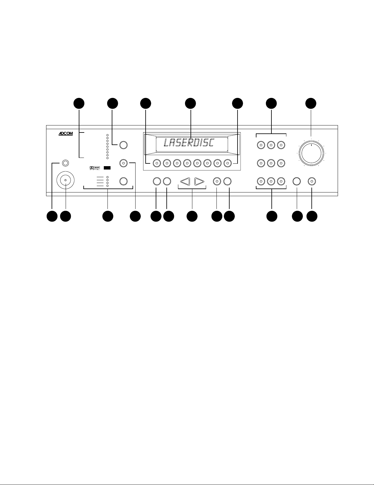
1.1 Front Panel Controls
The GTP-760’s front panel is a model of simplicity. All controls are logically grouped for easy , intuitive
operation. F amiliarize y ourself with the follo wing diagram and read the short explanations of each
feature. When you finish, y ou will be well on y our w a y to enjo ying the GTP-760’ s convenience and
sound quality .
33 7 6 8 14 15
DIGITAL
GTP-760
phones
DTS
Dolby Digital
Cinema
Dolby Pro Logic
symphony hall
stadium
jazz club
5-chan. stereo
2-chan. stereo
full
75%
50%
25%
DIGITAL
SURROUND
surround mode
dialog enhance
dynamic range
DVD digital 1 digital 2
RDS PROGRAM TYPE AM FM STEREO SEEK VOLUME MUTE PRESET
1234567shift (8-14) LD VCR video aux
FM/AM seek/manual < tuning > dim 5.1-channel in CD tape tuner room 2
18
1 2 5 4 9 10 11 12 13 14 16 17
1 Headphone Jack: This accepts the stereo 1/4" phone plug connector used by almost all high
quality headphones. When y ou use the headphone jack, the GTP-760’ s rear panel main line
lev el Preamp outputs are muted. Room 2 outputs are NO T aff ected.
2 Po wer Button and LED: Use this button to turn your GTP-760 ON and OFF. When y ou first
push the Po wer Button to the ON (depressed) position, the center LED will glo w yellow until all
circuitry stabilizes. When y our GTP-760 is ready to use, the LED will turn red.
NOTE:
panel Po wer Button is not depressed, the remote control will not ha ve an y eff ect. When the
front panel Po wer Button is engaged, the remote controller’ s “P o wer” button will cycle your
GTP-760 between standby and operation modes. When in standby mode (indicated b y the
yellow LED), y ou need to press the remote control’ s “Power” button to activ ate your GTP-760’s
circuitry (the LED will turn red when you do this).
The front panel Power Button must be engaged to use the remote control. If the front
3 Surround Mode Button and LED Indicators: Pushing the button sequentially steps your
GTP-760 through all the availab le operating modes for the selected input. The modes that are
not available for the current operating state are automatically bypassed.
For the 6 analog inputs, the choices are always the same -
Cinema, symphony hall, stadium, jazz club, 5-chan. stereo
Dolby Pro Logic, Dolby Pro Logic/
, and
2-chan. stereo
.
For digital inputs (D V D , digital 1 and digital 2) the choices are dynamic and depend on the type
of signal being input.
For DTS signals, the choices are
For Dolby Digital 5.1 channel signals, the choices are
Dolby Digital/2 chan. stereo
DTS, DTS/Cinema
.
and
DTS/2 chan. stereo
.
Dolby Digital, Dolby Digital/Cinema
6
and
Page 8

For familiar music CDs (also called PCM signals) the choices are the same as for analog
inputs,
stereo
option is not available and the GTP-760 automatically bypasses that choice.
4 Dialog Enhance Button: A shelving filter with a corner frequency of 7 kHz that reduces the
often excessive high frequencies on some movie soundtracks that make them fatiguing to
listen to. It also provides a boost in the midrange output for center and front channel speak ers.
5 Dynamic Range Button and LED Indicators: This button, usable only with a Dolb y Digital
source, incrementally reduces the audio track’s dynamic range in four steps (full, 75%, 50%,
and 25%) to allow comfortable listening under a wide variety of conditions. The normal, or
default, position is full.
Although we usually prefer to reproduce a source’ s full dynamic range (the diff erence between
very loud and very soft sounds), we occasionally need to reduce dynamics. For example,
when playing a movie late at night, loud explosions might wake sleeping family members.
Simply turning the volume control down would probably make a whisper in the next scene
inaudible. The Dynamic Range button solves this dilemma b y progressively lo wering the
volume of loud peaks while increasing the le v el of softer sounds . This allo ws y ou to hear every
element of the soundtrack without disturbing those around you or forcing you to strain to hear
delicate nuances.
6 Display Window: This shows all the pertinent information you will need to effectively use the
GTP-760 on a daily basis. W e carefully designed this window to displa y only the data y ou need
at the time you need it. The window’ s configuration will change as y ou ask the GTP-760 to do
different things. The displa y normally shows the input y ou’ve selected. If you’re currently
listening to AM or FM radio, the displa y sho ws that signal’s frequency . Additional information
appears as needed and we’ll note these appearances in subsequent sections of this manual.
Dolby Pro Logic, Dolby Pro Logic/Cinema, symphony hall, stadium, jazz club, 5-chan.
, and
2-chan. stereo
. Because CDs do not carry Dolby Digital signals , the
Dolby Digital
7 T uner Preset Buttons: These buttons allow quic k access to up to 14 preselected AM or FM
broadcast frequencies. To save presets, tune to the desired station and press one of these 7
buttons. Continue to hold the button until it lights and the display shows the preset n umber .
Use the Shift button in conjunction with these buttons to select and save presets 8-14.
8 Shift (8-14) Button: This allows each of the 7 tuner preset buttons to do “double duty. ” When
the LED in the center of the shift button is illuminated red, the 7 tuner preset buttons activate
tuner presets 8-14. When the LED in the center of the shift b utton is not illuminated, the 7
tuner preset buttons activate tuner presets 1-7.
9 FM/AM Button: As you might expect, this button selects AM or FM. In addition to the
selected broadcast frequency, a small “AM” or “FM” indicator appears in the bottom of the
Display Window to confirm your choice.
1 0 Seek/Manual Button: This controls the tuner’ s scan function and working of the tuning b uttons.
In SEEK - goes UP to the next available station.
In MANUAL - mo v es UP in increments to the desired frequency y ou select manually.
1 1 T uning Do wn/Up Buttons: These allo w easy selection of all the stations your GTP-760 can
receive. Remember that these Tuning buttons will scan to the next activ e or to the adjacent
frequency depending on how you’ve set the Seek/Manual button described above.
1 2 Dim Button: This reduces Displa y window brightness for listening or vie wing in a dark
room. The b utton simply switches betw een full and reduced illumination.
7
Page 9

1 3 5.1 Channel In Button: This b utton selects the 5.1 channel analog input, which allows the user
to enjoy high-resolution, multichannel f ormats such as D VD-Audio and Super A udio CD. This
pure analog input completely bypasses any digital conversion or processing to maintain the
highest possible audio quality; thus, delay and bass management are disabled and no surround
modes may be selected when using the 5.1 channel analog input. This input is selectable
from the front panel only.
1 4 Input Selector Buttons and LED indicators: These allow easy choice of any av ailable input.
When you select a particular input, the LED in the center of that button will light and the input
name will appear in the Display window to confirm your choice. Choosing an input automatically selects the Surround mode last used with that input. You may change the Surround mode
at any time by using the Surround Mode button (#3 above).
1 5 Master V olume Control: This rotary knob adjusts the volume f or all activ e speakers sim ulta-
neously. While it has the accustomed look and feel of the familiar analog volume control, it’s
internal implementation is digital. The distinction will be apparent only in that the knob will
NORMALLY be positioned near 12 o’clock for typical listening lev e ls. This will be true f or
all sources.
1 6 IR (infrared) Sensor: This small window receiv es commands from the remote controller . Do
not block this window with accessories, cables, CD jewelboxes, etc., or the remote control
will not work.
1 7 Room 2 Button: Pressing this button will activate the Room 2 output circuitry , enabling an y of
six analog audio and video sources; LD, VCR, video aux, CD , tape, and tuner . Pressing the
Room 2 button a second time will cause the LED’ s on the available source buttons to il
luminate. The source that is currently selected for Room 2 will be flashing. Choose the source
you want to send to Room 2 by pressing the desired source button, it will illuminate steadily
and the others will go off. Pressing and holding Room 2 for several seconds will turn the Room
2 output OFF.
1.2 Rear Panel Inputs & Outputs — System Connections
Like the front panel, the GTP-760’ s rear panel is carefully arranged to mak e hookup,
configuration, and use as simple as possible. How e ver , the GTP-760’ s e xtraordinary
capabilities take some study to use most effectively. We strongly suggest that you read this
section of the manual before beginning to hook up your system. You will sav e y ourself much
time and effort if you carefully think out what you expect from your system: consider the
components you will use, where the y’ll be placed, and how you will w ant them to work together .
The diagrams and notes in this section will probably answer most of your questions about interfacing
the GTP-760 with other components in your system. You will find more detailed information on initial
setup and configuration in following sections of the manual.
Note that the GTP-760’s RCA-style jac ks hav e color-coded centers to mak e connections
easier. Use this key to help route cables properly:
YELLOW centers = VIDEO inputs (composite)
BLACK centers = DIGITAL A UDIO inputs
CENTER CHANNEL and SUBWOOFER
PREAMP inputs and outputs
WHITE centers = LEFT CHANNEL ANALOG AUDIO inputs
RED centers = RIGHT CHANNEL ANALOG AUDIO inputs
and
8
Page 10

Composite or S-Video?
One of the first system hook-up decisions to make will be which video format to use. While the composite
video format is more widely used, S-Video can offer improv ed picture quality. The GTP-760 does not
convert between the two f ormats. Howev er, it can save the video mode for each input. It is
recommended that only one video format be used as this simplifies normal operation. How e ver , setup f or
using both formats is also described below. The GTP-760 is shipped from the factory ready for composite
video sources and display devices.
For Composite Video Onl y: If y our tele vision has only composite video inputs (usually a y ellow colored
RCA style connector) or you elect to use only composite video connections in your system, then the
GTP-760 is already properly set. Connect a video cable from one of the two yellow “standard monitor”
video jacks on the back of the GTP-760 to the video input of y our tele vision. Turn on the GTP-760 and
television and verify a blue colored screen. If you are unable to get the blue screen, consult your television
owner’ s manual to determine how to select the appropriate television input. If y ou are certain your
television is in the correct mode, follow directions 1 through 3 below (S-Video only). Repeat that procedure
until the GTP-760 display reads COMPOSITE at the completion of step 3.
For S-Video Only: If your television has an S-Video input and all of your video source components have
S-Video outputs, then you will probably elect to use only S-Video connections in you home theater system.
The following steps will switch the GTP-760 to S-Video operation.
1) Turn the GTP-760 off via the front panel power switch.
2) On the front panel, hold the surround mode button down and power the unit ON.
3) Continue to hold the surround mode button until the front panel displa y of the GTP-760 reads S-VIDEO .
The GTP-760 is now set for S-VIDEO operation. (Note: Repeating the procedure returns the unit to
composite mode and COMPOSITE shows in the display). Connect an S-Video cable from one of the two
“S-video monitor” jac ks on the back of the GTP-760 to the S-Video input of y our tele vision. Turn on the
GTP-760 and television and verify a light gray colored screen. If you are unable to get the gray screen,
consult your television owner’ s man ual to determine how to select the appropriate television input.
For using both Composite and S-Video: While more difficult to do , y ou ma y elect to use both video
modes, if some of your video sources have composite video only and others have S-Video capability. This
connection also requires that your television accepts both formats. A common scenario would be
connecting both a VCR that has composite video only and a DVD player that has S-Video capabilities to
your GTP-760. The GTP-760 will not con v ert between the different video types, but will remember the
video mode for each of its inputs. Thus , when y ou select VCR, the GTP-760 switches to composite video
mode. When y ou select DVD , the GTP-760 switches to S-Video mode . Consequently, to operate your
system in this way connect BOTH a composite video cable from one of the “standard monitor” jac ks on the
back of the GTP-760 to the composite input on your television AND an S-Video cable from one of the
“S-Video monitor” jacks on the back of the GTP-760 to the S-Video input of your television. (Note, in this
example, the GTP-760 s witches modes automatically, but you will still need to manually change the mode
of your television an ytime you s witch between these inputs). Turn on the GTP-760 and television and
verify a blue colored screen. If you are unable to get the b lue screen, consult y our tele vision o wner’s
manual to determine how to select and use the television’ s video inputs . All of the GTP-760 inputs are
initially set for composite mode. Consult section 3.5 INPUT SETTINGS discussion of the VIDEO field to
use the GTP-760 on screen display to save the S-Video mode settings for your S-Video sources.
9
Page 11
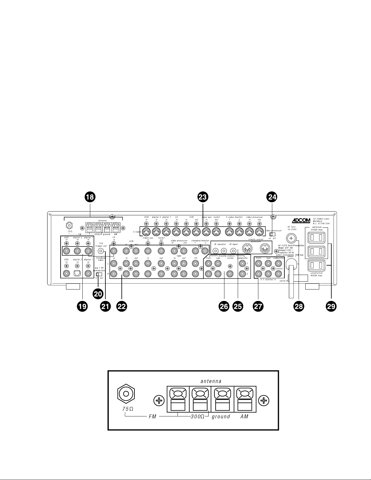
18 Antenna connections
19 Digital audio/standard (composite) video inputs
DVD
Digital 2
Digital 1 ( RF )
20 Digital 1 RF Demodulator switch
2 1 12 volt trigger output
22 Analog audio/standard
(composite) video inputs and outputs
LD (laserdisc) inputs
VCR inputs and outputs
Video aux in
Room 2 outputs
Video Processor inputs and outputs
Tape inputs and outputs
Standard (composite) video monitor outputs
CD inputs
2 3 S-Video inputs and outputs
D VD input
Digital 2 input
Digital 1 input (RF)
LD input
VCR input
VCR output
Video aux input
Room 2 output
S-Video monitor outputs
Video Processor input and output
2 4 Video Processor On/Off switch
25 Remote control connections
Infrared repeater outputs
Remote sensor extension outputs
26 Preamplifier outputs
2 7 5.1 inputs
2 8 AC power cord and AC fuse holder
2 9 AC convenience outlets
1 8 Antenna Connections: You need to connect different antennas for FM and AM reception.
10
Page 12
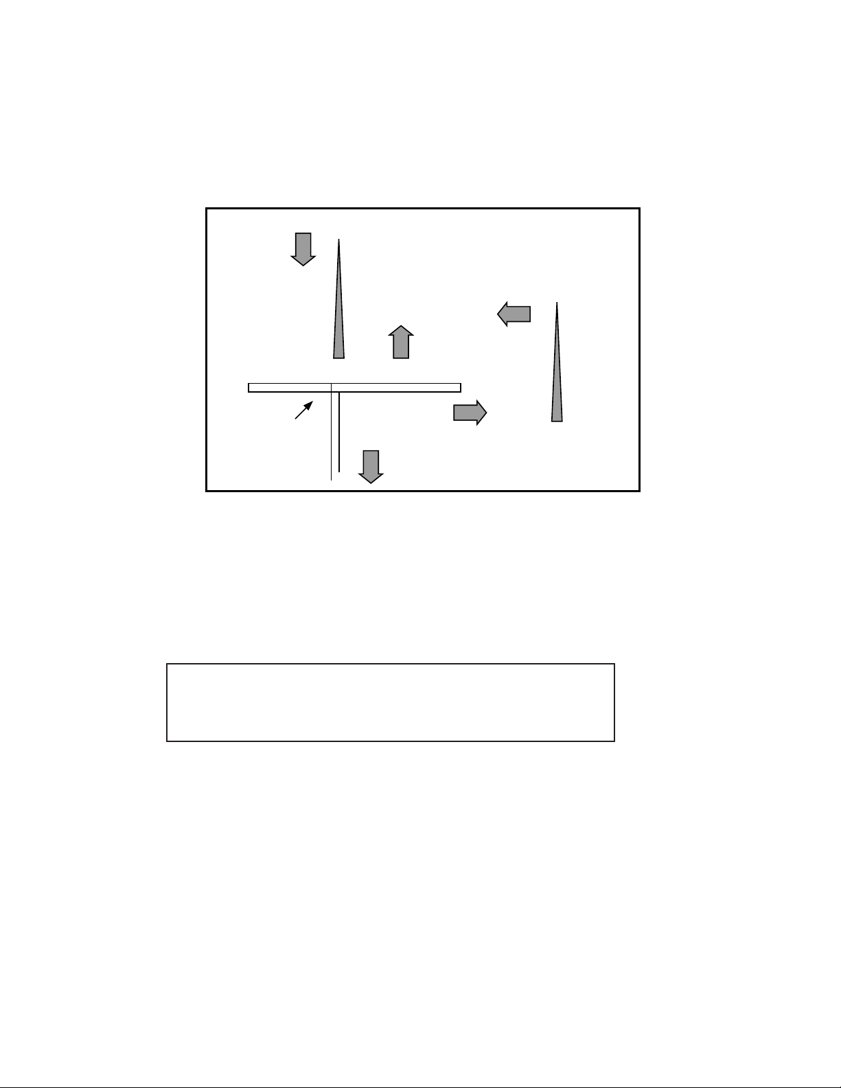
For FM, use either the 75 ohm “F” connector or the 300 ohm “push terminals” depending on
what type of antenna you’ve chosen. If you’re getting FM from a cable system feed, you will
most likely use the “F” connector . The “T” shaped antenna supplied with the GTP-760 uses the
push terminals marked “300 ohms.” “T” antennas are directional. They should be placed as
high as possible with the arms fully extended. If possible, the arms should be oriented so that
they are at right angles to the transmitter .
signal direction
transmitter
best reception
FM antenna
poor reception
to GTP-760 FM
antenna connection
The supplied AM loop antenna connects to the push terminals marked “ground” and “AM,”
respectively. You may need to adjust the position of the antenna for best reception. If you use
an outdoor AM antenna, follow the manuf acturer’ s instructions.
19 Digital Audio/Standard (Composite) Video Inputs
Remember that you must choose either standard (composite) or S-Video
connections before hooking up source components. This section of the
manual assumes you have chosen composite connections. S-Video
connections will be handled in a subsequent section.
signal direction
transmitter
DVD in: Connect the DVD player’s composite video output to the y ellow-center RCA jac k
immediately under the “D VD in” label.
Connect the D VD play er’ s RCA-style digital output jac k to the GTP-760’ s b lack-center RCA
jack located under the “D VD in” label.
Note:
If your DVD player has only a TOSlink (optical) digital output, you ma y need to connect it
to “dig.2 in.” If this is the case, remember to connect the player’s video output (composite or S-
11
Page 13

DVD
in in in
digital 2 digital 1
LD
in
12V
trigger out
DVD
in in in
digital 2 digital 1
Standard
video
dig1RF
demodulator
in out
in
L
R
Video) to the appropriate “dig.2 in” jack.
Digital 2 in: This input is recommended f or an audio/video source (DSS receiv er , etc.) with a
TOSlink (optical) digital output.
Remember that the composite video connection will go to the yellow-center RCA jack
immediately under the “dig.2 in” label.
Connect the source’s T OSlink (optical) digital output to the GTP-760’s TOSlink sock et located
under the “dig.2 in” label.
Digital 1 in (RF): W e recommend this input for laserdisc pla y ers with a digital RF output.
It is the only input on the GTP-760 equipped with the RF demodulator needed to process a
laserdisc’s Dolb y Digital encoded soundtrac k.
Connections follow the same pattern detailed in “DVD in” and “Dig.2 in” above . Connect the
laserdisc play er’ s composite video output to the yellow-center RCA jac k immediately under the
“dig.1” label. Then connect the pla y er’s coaxial digital output to the black-center RCA jack
under the “dig.1 in” label.
20 Digital 1 RF Demodulator (bypass) Switch
(see illustration on preceding page)
This switch adds flexibility to the GTP-760. If you play laserdiscs with Dolby Digital-encoded
soundtracks, put this switch in the IN position. This places the demodulator circuit in the signal
path and allows proper Dolby Digital decoding.
If you do not have a laserdisc player with a digital RF output, place the switch in the OUT
position. You can then use this input in exactly the same way as you would use the DVD input.
12
Page 14
2 1 12 V olt T rigger Output
(see illustration on preceding page)
To facilitate remote turn-on and turn-off of other components (power amplifiers, for e xample),
this 2.5 mm mini-jack provides a constant signal (12 volts DC) whenever the GTP-760 is fully
powered. When the GTP-760 is turned off (via the front panel switch) or placed in standby
mode (via the “power” button on the remote control), the jack has no output.
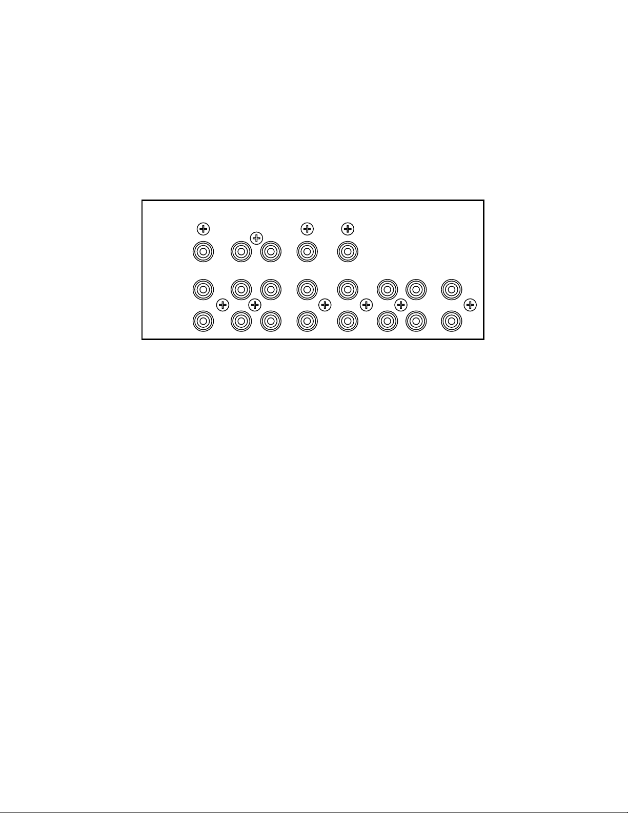
2 2 Analog Audio and Standard (Composite) Video Inputs and Outputs
Standard
video
LD (laserdisc) Inputs:
Use these inputs as you have already used the digital source inputs (see #19 above.) After
selecting and connecting the laserdisc player’ s composite video output to the GTP-760’s
yellow-center RCA jac k immediately under the “LD in” label, connect the pla yer’ s left channel
analog audio output to the white RCA jack under the “LD in” label. Then connect the pla yer’ s
right channel analog audio output to the “LD in” red RCA jack.
VCR Inputs and Outputs:
Because you will use your VCR to record as well as play, take care to follow these
instructions carefully.
LD
in
VCR
in out
video auxinroom2
out
outinoutinin
tape
CDoutin
1) Connect the VCR’s composite video output to the GTP-760’s y ellow-center RCA jac k
immediately under the “VCR in” label.
2) Connect the VCR’s composite video input to the GTP-760’s yellow-center RCA jac k
immediately under the “VCR out” label.
3) Connect the VCR’s left channel analog audio output to the GTP-760’s white “VCR in” jack.
4) Connect the VCR’s right channel analog audio output to the red “VCR in” jack.
5) Connect the VCR’s left channel analog audio input to the GTP-760’s white “VCR out” jack.
6) Connect the VCR’s right channel analog audio input to the red “VCR out” jack.
Note: You may want to use so-called “A/V combination” patch cords to make this step less
confusing. Sold under a variety of names, these combination cables usually include a video
conductor and two audio conductors in one cable assembly. If y ou elect to use them, make
sure that they support the video format (composite or S-Video) you’ve chosen f or y our system.
13
Page 15

Video Aux Input:
This input is electrically identical to the LD input described above and will accommodate a wide
variety of audio/video sources.
After selecting and connecting the source’s composite or S-Video output to the GTP-760’s
corresponding “video aux” video input, connect the source’s left channel analog audio output to
the white RCA jack under the “video aux in” label. Then connect the source’s right channel
analog audio output to the red RCA jack under the “video aux in” label.
Room 2 Outputs:
These outputs supply video and audio
signals for distribution to a secondary
area or room in your home. Room 2
features are covered in section 4.3 of
this manual.
Connect the composite Room 2 video
output to the video display device (TV
or videoprojector) in the remote area.
Make sure the cable(s) you use for this
connection are high quality and well
shielded as long cable runs act as
antennas for unwanted interference signals.
digital 2 digital 1 LD
in in in in out in out
room2
out
video processor
in out
out
L
R
tape
VCR video aux room2
standard monitor
12
IR repeater
rearfrontCDoutin
(Depending on the distance between the GTP-760 and the display device and, to a lesser
extent, the video format you’ve chosen, you may need a video distribution amplifier to make
sure the signal arrives at the display de vice properly. Consult your ADCOM dealer f or
additional information if needed.)
Connect the white “Room 2 out” jack to the left channel input of the amplifier used to power
speakers in the remote area. Then connect the red “Room 2 out” jac k to the amplifier’ s right
channel input.
Video Processor Inputs and Outputs:
These connections allow easy interface with video processors. Note that a separate video
processor handles video signals only so you don’t need to concern yourself with any audio
connections between it and the GTP-760. ( For additional information, consult your video
processor’s manual )
Connect the processor’s composite video output to the GTP-760’s
video processor
in out
yellow-center “Video Processor in” jac k. Then connect the video
processor’s composite input to the GTP-760’ s y ellow-center “Video
Processor out” jack.
If you are using the GTP-760 with a separate video processor , mak e
sure you’ve set the Video Processor switch to the “ON” position.
14
Page 16

T ape Inputs and Outputs:
tape
L
R
CDoutin
Follow these instructions:
1) Connect the recorder’s left channel analog audio output to the GTP-760’ s white
“tape in” jack.
2) Connect the recorder’s right channel analog audio output to the red “tape in” jack.
3) Connect the recorder’s left channel analog audio input to the GTP-760’s white
“tape out” jack.
4) Connect the recorder’s right channel analog audio input to the red “tape out” jack.
Standard (Composite) Video Monitor Outputs:
Connect the main monitor or display device to the yellow-center RCA jack
standard monitor
12
under the “standard monitor 1” label. Y ou ma y use the “standard monitor 2”
jack for another monitor if desired. Properly connected, either monitor will
then display an image from a video source or on-screen menu information
when appropriate.
These connections are designed for a cassette deck
or any other audio recording device with line-level
analog inputs and outputs.
CD Inputs:
These line-level analog inputs allow easy connection of a CD player (or other two channel
analog audio source.)
Follow these instructions:
1) Connect the CD player’ s left channel analog audio output to the GTP-760’s white
“CD in” jack.
2) Connect the CD player’s right channel analog audio output to the red “CD in” jack.
15
Page 17

23 S-Video Inputs and Outputs
Note: This section assumes that you’ve elected to use S-Video sources and displa y de vices and that
you’ve set the GTP-760 for S-Video signal transfer by following the steps described in the boxed note
entitled Composite or S-Video? on page 9.
digital 2 digital 1 LD VCR video aux room2 S-video monitor
in in in in in out in out 1 2 in out
S-video
video processorDVD
When hooking up S-Video capable audio/video components, follow the steps outlined in Sections 19
and 22 above . How e ver, ignore the instructions for composite video connections and substitute
the following:
DVD in: Connect the D VD pla yer’ s S-Video output to the mini-DIN connector under the S-Video
“D VD in” label.
Digital 2 in: Connect the source’ s S-Video output to the mini-DIN connector under the S-Video
“dig. aux in” label.
Digital 1 in (Dolby Digital RF optional): Connect the source’ s S-Video output to the mini-DIN
connector under the S-Video “digital 1 in” label.
LD in: Connect the LD play er’s S-Video output to the mini-DIN connector under the S-Video
“LD in” label.
VCR in: Connect the VCR’ s S-Video output to the mini-DIN connector under the S-Video
“VCR in” label.
VCR out: Connect the VCR’ s S-Video input to the mini-DIN connector under the S-Video
“VCR out” label.
Video aux in: Connect the source’s S-Video output to the mini-DIN connector under the S-Video
“video aux in” label.
Room 2 Output: Connect the video display device to the S-Video mini-DIN output under the
“room 2 out” label.
S-Video Monitor Outputs: Connect the main monitor or display device to the mini-DIN jack
under the “S-Video monitor 1” label. You ma y use the “S-Video monitor 2” jack f or
another monitor if desired. Properly connected, either monitor will then display an
image from a video source or on-screen menu information when appropriate.
Video Processor Input and Output: Connect the Video Processor’s S-Video output to the mini-DIN
jack immediately under the “video processor in” label. Then connect the video
processor’s S-Video input to the mini-DIN jac k under the “video processor out” label.
16
Page 18

24 Video Processor On/Off Switch
This switch controls a “video loop” that enables the GTP-760 to function with a separate
video processor.
For conventional home theater systems, make sure the “video pr ocessor on/off” switch is in the OFF
position. When using a separate video processor , place this s witch in the ON position.
25 Remote Control Connections
remote sensor
IR repeater IR input
extension
. Infrared Repeater: These mini-jac k outputs transfer command codes receiv ed from either the IR
mini-jack or remote sensor extension inputs to an IR repeater located close to other
system components. IR signals receiv ed at the GTP-760’ s front panel IR receptor are
NOT
availab le at the infrared repeater outputs.
Remote Sensor Extension Inputs: These inputs receiv e signals from ADCOM’ s XR500II and
SPM500II remote control sensors.
IR (Infrared) Input: This input accepts modulated IR commands from industry standard IR
controllers via a mono mini-plug connector .
26 Preamplifier Outputs
These are the GTP-760’s main outputs . Connect each to the proper amplifier or amplifier channel
as follows:
1) Connect the white-center RCA output marked “front L(eft)” to the amplifier channel
designated for the left front loudspeaker.
2) Connect the red-center RCA output marked “front R(ight)” to the amplifier input designated
for the right front loudspeaker.
3) Connect the white-center RCA output marked “rear L(eft)” to the amplifier input designated
for the left rear loudspeaker.
4) Connect the red-center RCA output marked “rear R(ight)” to the amplifier input designated
for the right rear loudspeaker.
5) Connect the black-center RCA output marked “center” to the amplifier input designated for
the center channel loudspeaker .
6) Connect the black-center RCA output marked “subwoofer” to the amplifier input
(in most cases, the line-level input of a powered subwoofer) designated for
the subwoofer.
preamp outputs
L
R
subwooferrear centerfront
1
2
Note: There are two subwoofer outputs (1 & 2.) The y are in parallel (i.e., each produces an
identical signal) and may be used interchangeably. We’ve included these outputs to make it
easier to add a second subwoofer , if desired. Alternatively, you can connect the LEFT and
RIGHT channel RCA jacks to a single subwoofer.
17
Page 19

27 5.1 Channel Inputs
front
rear subwoofer
These are the multichannel analog inputs. Connect your D VD-
center
5.1-channel in
Audio , SA CD or other multichannel source as f ollows:
1) Connect the source’s “front left” output to the white-centered RCA input marked “front”.
2) Connect the source’s “front right” output to the red-centered RCA input marked “front”.
3) Connect the source’s “surround left” output to the white-centered RCA input marked “rear”.
4) Connect the source’s “surround right” output to the red-centered RCA input marked “rear”.
5) Connect the source’s “center” output to the b lack-centered RCA input marked “center”.
6) Connect the source’s “subwoof er” output to the blac k-centered input marked “subwoof er”.
Note: The GTP-760 does not apply bass-management to the 5.1 channel analog inputs, and all
six input channels will pass full range signals. Some multichannel sources may not make use
of bass-management techniques. Please read the multichannel source’ s manual carefully to
ensure correct operation.
28 AC Fuse Holder **CAUTION** UNPLUG the unit bef ore checking the fuse!
This holder provides easy access to the AC line fuse if that fuse needs replacement. To gain access to
the fuse, insert a Phillips head screwdriver and turn counterclockwise. After replacing the fuse , reseat
the holder by turning clockwise until the holder is firmly seated.
When replacing the fuse, AL WAYS use one of equal v alue (f or domestic models use a F500mA, 250V
fuse availab le at any electronic parts store.) NEVER use a fuse of higher value. If the fuse fails again,
consult your ADCOM dealer or call the ADCOM Service Department directly.
AC P ower Cor d (115V AC models)
Make sure to seat this cord firmly in an unswitched wall socket to provide uninterrupted power to the
GTP-760. When remo ving the cord from an AC socket, NEVER pull on the cord itself. Instead,
grasp the plug firmly and remove it from the sock et. You may need to “rock” the plug lightly for
easier removal.
AC P ower Cord Receptac le (export models)
This IEC-standard socket accepts a wide variety of AC power cords.
18
Page 20

29 AC Con venience Outlets (115V AC models)
These outlets are for low-current sour ce components onl y. They are not
designed for power amplifiers.
The single unswitched outlet is liv e whenever the GTP-760 is plugged into a live AC source. The two
switched outlets are live only when the GTP-760 is fully operational (i.e., whenever the front power
button’ s LED is red.) They are not live when the GTP-760 is in standb y mode (when the LED is y ellow.)
Observe the wattage limitations printed above the two switched and one unswitched outlets. Note that
the 500V A figure (equiv alent to 500 w atts) abov e the tw o s witched outlets is a maximum figure f or both
outlets combined. Do not exceed this limit.
We strongly recommend the use of our surge suppresser/ line conditioners, the ADCOM ACE family of
products, for systems with substantial amplifiers and man y source components . The A CE products
relieve the GTP-760 from handling large current surges, while they protect your entire system by
filtering and conditioning the AC current. In addition to the numerous heavy duty AC outlets of the
ACE-315, the ACE-615 includes sequential power-up and power-down modes to minimize “thumps”
whenever you turn your system on or off.
1.3 The Remote Control
The GTP-760 remote control is a learning remote control that is capable of saving commands for all
remote controls in your home theater system. In this way, you may eliminate the confusion of using
multiple remotes. Although such po w er comes with some added comple xity, the complexity is minimal
and with some repetition will become second nature.
The single most important aspect to master about the GTP-760 remote control is the function of the
eight source select buttons at the top of the remote. These are b uttons 30 in the figure on the ne xt
page. Each of these buttons cause two things to happen when used. First, they select the
corresponding input on the GTP-760. Second, THESE KEYS REMAP ALL OF THE OTHER B UTT ONS
ON THE REMOTE CONTROL. You can think of each of these buttons as having a page of commands
associated with it.
Most of the GTP-760 remote commands are saved under the main remote page . Whenev er y ou desire
to control the GTP-760 via remote, you must first ensure the main page is active. As an example,
press main on the remote control. Now, press the dim button. If your GTP-760 is on, the brightness of
the front panel display changes. Notice also that the main button on your remote illuminates. This
serves as a reminder that the main remote page is currently active.
Now press the CD button and then the select/play button. Notice now that the CD source button lights.
The CD remote page is now active. If you have an ADCOM CD player, this command will cause an idle
CD to play. Now, press the dim button again. You should note that CD button does not light. The dim
command is not preprogrammed in the CD remote page. If your GTP-760 is on you will also notice the
display does not respond to this command. Press the main button again to reenter the main remote
page. The dim button will now again change the GTP-760 displa y.
The button description that follows distinguishes the function of each button dependent on the page the
remote is in. The remote is shipped from the f actory with ADCOM commands sav ed under the main ,
tuner and CD pages.
The ADCOM universal remote controller is preset to operate most GTP-760 functions (MAIN
device mode), GTP-760 AM/FM tuner functions (TUNER device mode) and GCD-700/750 CD
functions (CD device mode).
19
Page 21

30 Source selectors
main
DVD
dig.1 (digital RF — digital LD)
dig.2 (digital auxiliary)
tuner
CD
VCR
v . aux (video auxiliary)
31 Power
3 2 Input selectors
33 Volume Up/Down
34 T uning Up/Down
35 Guide
36 Menu
37 < (left arrow)
38 Up arrow/Pause
39 > (right arrow)
40 Down arrow/Stop
4 1 Select/Play
4 2 Direct access keypad
(“1” through “10” and “+10”)
4 3 Shift
4 4 FM/AM
45 Stereo
46 Srnd (surround)
47 Enter
48 d. (dynamic) range
49 dialog
5 0 Level trim
Rear Up/Down
Center Up/Down
Sub Up/Down
5 1 Bal. chk (balance check)
52 Dim
5 3 M1, M2, M3, M4 (Macro keys)
54 Room 2
55 Backlight
56 Mute
5 7 Status LED light
57
30
31
32
35
38
40
42
48
49
53
37
Adcom tuner/preamp
main Dig.2Dig.1DVD
CDtuner
power
tape
LD
guide
pause
select
play
stop
exit
231
4
7
+10 0
m1 m2
room2
5
8
rear center sub dimdialog
backlight
digital LD
v.aux
VCR
tuningvolume
tuner preset scan
menu
delay
FM/AM
stereo
6
9
srnd
entershift
bal.chkd.range
m3 m4
mute
34
33
41
II
39
44
45
46
43
47
51
52
50
20
54 55 56
Page 22

3 0 Source Selectors (main, DV D, VCR, tuner , v. aux, CD, dig.1, dig.2.)
These buttons serve two functions.
• First, they switch inputs on the GTP-760 so you can hear the source you’ve just selected.
• Second (and ev en more important),
remote controller
button generates a command code f or y our DVD player. If you then press the dig.2 device selector,
the same select/play button would send a diff erent command code that might, f or e xample, start
your mini-disc play er. (Of course, this all depends on ho w y ou prog rammed the remote in the first
place. Don’t worry-we’ll cover that shortly .)
31 Power
•In main mode (after you’ve pressed the main device selector), this is preprogrammed to turn the
GTP-760 on and off.
•In tuner mode, it is also preprogrammed to turn the GTP-760 on and off.
• The button is programmable for use with other sources.
32 Input Selectors (tape, LD)
•In main mode, these are similar to the source selectors described above but they switch only
GTP-760 inputs. The y DO NOT automatically change the functions of other remote b uttons.
• These buttons are programmable for use with other sources.
3 3 V olume Up/Down
• These are the only buttons preprogrammed at the factory with the same command.
In all modes, these buttons change the master volume setting of the GTP-760.
. In other words, if y ou first push the DVD device selector, the remote’s select/play
they can change the functions of all the other buttons on the
3 4 T uning Up/Down
•In tuner mode, these buttons are preprogrammed to scan up or do wn the GTP-760’ s AM or FM band.
• They are programmable for use with other sources.
35 Guide
• This is intended for easy call-up of cable or satellite program guides.
• Button is programmable for use with any source.
•In CD mode, it is preprogrammed for audible reverse scan with an ADCOM CD player
36 Menu
•In main mode, this is preprogrammed to call up the GTP-760’ s SETUP menu system.
(A subsequent push will exit the menu, regardless of which menu screen you are in.)
• It is programmable for use with any source.
•In CD mode, it is preprogrammed for audible forward scan with an ADCOM CD player
37 < (left arrow)
•In main mode, this is preprogrammed to step through the various choices you might wish to select
while a menu item is highlighted.
•In CD mode, it is preprogrammed for audible reverse scan with an ADCOM CD player
• The button is programmable for use with any other source.
38 Up arrow/Pause
•In main mode, this is preprogrammed to scroll up to the next choice on a menu screen.
•In CD mode, it is preprogrammed to pause an ADCOM CD pla yer .
•In tuner mode, it is preprogrammed to start scanning preset frequencies higher than the
current station.
• The button is programmable for use with any other source.
3 9 > (right arrow)
•In main mode, this is preprogrammed to step through the various choices you might wish to select
while a menu item is highlighted.
•In CD mode, it is preprogrammed for audible forward scan with an ADCOM CD player
• The button is programmable for use with any other source.
21
Page 23

40 Down arrow/Stop
•In main mode, this is preprogrammed to scroll down to the next choice on a menu screen.
•In CD mode, it is preprogrammed to stop an ADCOM CD play er .
•In tuner mode, it is preprogrammed to start scanning preset frequencies lower than the
current station.
• The button is programmable for use with any other source.
41 Select/Play
•In main mode, this is preprogrammed to enter a selection chosen via the menu system.
•In CD mode, it is preprogrammed to start an ADCOM CD player .
• The button is programmable for use with any other source.
42 Direct Access Keypad (buttons “1” through “10, ” and “+10”)
•In T uner mode, buttons “1” through “7” are preprogrammed to access preset stations .
•In CD mode, buttons are preprogrammed as trac k access commands for the ADCOM CD pla y er .
• The buttons are programmable for use with any other source.
43 Shift
•In T uner mode, button is preprog rammed to access presets 8 through 14 (“Shift” + “2” = preset
number 9, etc.)
•In CD mode, button is preprogrammed as “call” command for ADCOM CD pla yer .
• The button is programmable for use with any other source.
44 FM/AM
•In Tuner mode, button is preprogrammed to switch between FM and AM bands.
•In CD mode, button is preprogrammed as “repeat” command f or ADCOM CD play er.
• The button is programmable for use with any other source.
45 Stereo
•In Tuner mode, b utton will change playbac k from Stereo to Mono .
•In CD mode, button is preprogrammed as “program/memory” command for ADCOM CD pla yer .
• The button is programmable for use with any other source.
•In main it will switch to 2 channel.
46 Srnd (surround)
•In main mode, button is preprogrammed to step through GTP-760’ s various operation modes.
•In CD mode, button is preprogrammed to initiate random play with ADCOM CD pla yer .
• The button is programmable for use with any other source.
47 Enter
•In tuner mode, button is preprogrammed to select “manual” or “seek” tuning modes.
•In CD mode, button is preprogrammed as “time” command for ADCOM CD pla yer .
• The button is programmable for use with any other source.
48 d. (dynamic) range
•In main mode, button is preprogrammed to adjust dynamic range of Dolby Digital encoded sources.
•In CD mode, button is preprogrammed to access disc 1 with ADCOM CD pla yer.
• The button is programmable for use with any other source.
49 dialog
•In main mode, button is preprogrammed to call up or cancel “dialog enhance” equalization.
•In CD mode, button is preprogrammed to begin and end “A-B” repeat with ADCOM CD play er.
• The button is programmable for use with any other source.
22
Page 24

50 Level trim (Rear Up/Down, Center Up/Down, Sub Up/Down)
Rear Up
•In main mode, button is preprogrammed to increase both rear speaker le v els simultaneously.
•In CD mode, button is preprogrammed to access disc 2 with ADCOM disc pla yer.
• The button is programmable for use with any other source.
Rear Down
•In main mode, button is preprogrammed to decrease both rear speak er lev els simultaneously.
•In CD mode, button is preprogrammed to clear “repeat” command with ADCOM disc pla yer .
• The button is programmable for use with any other source.
Center Up
•In main mode, button is preprogrammed to increase center channel speaker level.
•In CD mode, button is preprogrammed to access disc 3 with ADCOM disc play er .
• The button is programmable for use with any other source.
Center Down
•In main mode, button is preprogrammed to decrease center channel speaker level.
• The button is programmable for use with any other source.
Sub Up
•In main mode, button is preprogrammed to increase subwoofer level.
•In CD mode, button is preprogrammed to access disc 4 with ADCOM disc play er .
• The button is programmable for use with any other source.
Sub Down
•In main mode, button is preprogrammed to decrease subwoofer level.
• The button is programmable for use with any other source.
51 Bal. chk (balance check)
•In main mode, button is preprogrammed to initiate balance check procedure with test tone and
BALANCE CHECK menu screens.
•In CD mode, button is preprogrammed to access disc 5/Memory Clear with ADCOM disc player.
• The button is programmable for use with any other source.
52 Dim
•In main and tuner modes, button is preprogrammed to dim GTP-760’ s inf ormation display.
• The button is programmable for use with any other source.
53 M1, M2, M3, M4 (Macro keys)
M1
• In main mode, button is preprog rammed to select Tape 2 input (not applicable to GTP-760.)
• The button is programmable for use with any other source.
M2
• In main mode, b utton is preprogrammed to select Video 4 input (not applicable to GTP-760.)
• The button is programmable for use with any other source.
M3 and M4
• These buttons are programmable for use with any source.
5 4 Room 2
•In main mode, button is preprogrammed to turn Room 2 on, show Room 2 status and turn Room 2 off.
• The button is programmable for use with any other source.
55 Backlight
• No programming capabilities. Button backlights all keys for eight (8) seconds when pressed.
56 Mute
•In main, tuner, and CD modes, button is preprogrammed to mute outputs of de vice.
• The button is programmable for use with any other source.
57 Status LED
• Lights in different colors and patterns during learning operations as descriped in the remote
programming section
23
Page 25

Remote Function Table
This table supplements the information you’ve just read. Use it to quickly re view button functions. The
controller’s capabilities are extensive and may be somewhat intimidating at first. Howev er, you will soon find
that its logical button arrangement and programming capabilities will greatly increase your enjoyment as you
discover the ease with which you can operate your entire system from just one remote!
Look down the left-hand column until you see the button y ou want to learn about. Then look under MAIN to see
if it is preprogrammed for a GTP-760 function, under CD to see what CD commands are preprogrammed, and
under TUNER to see all preprogrammed tuning functions .
BUTTON FUNCTION
Main C D T uner All Others
MAIN Selects MAIN
DVD Selects DVD None None None
VCR Selects VCR None None None
TUNER Selects TUNER in None None None
V. AU X Selects VIDEO AUX None None None
CD Selects CD None None None
Dig.1 Selects DIGITAL 1 (RF) None None None
Dig.2 Selects DIGITAL 2 None None None
PO WER Power On/Off & Macro
TUNING +
TUNING -
Not programmable
Not programmable
V OLUME + Master volume up Master volume up Master volume up Master volume up
VOLUME - Master volume down Master volume down Master volume down Master volume down
T APE Selects TAPE Programmable
LD Selects LD Programmable
GUIDE
Not programmable
MENU On-screen display Track forward
EXIT
Not programmable
DELAY Sets rear chan. delay Open/close drawer
UP/P A USE OSD scroll up Pause Preset Scan +
DOWN/STOP OSD scroll down Stop Preset Scan -
< OSD left select Search reverse
> OSD right select Search forward
SELECT/PLA Y OSD “Enter” command Play
1
2
3
4
5
6
7
8
9
Not programmable
Not programmable
Not programmable
Not programmable
Not programmable
Not programmable
Not programmable
Not programmable
Not programmable
Not Programmable
Po wer On/Off
Disc Skip + Tuning +
Disc Skip - Tuning -
Programmable Programmable
Programmable Programmable
Track reverse
Polarity
Programmable Programmable
Programmable Programmable
Programmable Programmable
Programmable Programmable
Programmable Programmable
Programmable Programmable
Programmable Programmable
Track 1 Preset 1
Track 2 Preset 2
Track 3 Preset 3
Track 4 Preset 4
Track 5 Preset 5
Track 6 Preset 6
Track 7 Preset 7
Track 8
Track 9
Programmable Programmable
Programmable Programmable
Not Programmable
Programmable
Programmable
Programmable
Programmable
Programmable
Programmable
Programmable
Programmable
Programmable
Programmable
Programmable
24
Page 26

BUTTON FUNCTION
Main C D T uner All Others
0
+ 10
SHIFT
FM/AM
STEREO Stereo mode select Prog ram /Mem. Stereo/Mono
SRND Surround mode select Random play
ENTER
D. RANGE Dynamic range adjust Disc 1
REAR + Rear level up Disc 2
CENTER + Center level up Disc 3
SUB + Subwoofer level up Disc 4
BAL. CHK Balance check Disc 5/Memory clear
DIALOG Dialog enhance on/off A-B repeat
REAR - Rear level down Clear repeat
CENTER - Center level down
SUB - Subwoofer level down
DIM Dim display
Not programmable
Not programmable
Not programmable
Not programmable
Not programmable
Track 10
+ 10
Cal l Presets 8 - 14
Repeat FM or AM select
Time display Seek/Manual
Programmable Programmable Programmable
Programmable Programmable Programmable
Programmable
Programmable Programmable
Programmable Programmable
Programmable
Programmable
Programmable
Programmable Programmable
Programmable
Programmable Programmable
Programmable Programmable
Programmable Programmable
Programmable Programmable
Programmable Programmable
Programmable Programmable
Programmable Programmable
Dim Display
Programmable
M1 For Macro use For Macro use For Macro use For Macro use
M2 For Macro use For Macro use For Macro use For Macro use
M3 For Macro use For Macro use For Macro use For Macro use
M4 For Macro use For Macro use For Macro use For Macro use
ROOM 2 Room 2 source select
MUTE Mute volume Mute volume Mute volume
Programmable Programmable Programmable
Programmable
PROGRAMMING YOUR ADCOM GTP-760 REMOTE CONTROLLER
Introduction
The ADCOM universal remote controller operates eight different audio/video components. As you’ve already
seen, it’s preprog rammed to control ADCOM’ s GTP-760 Preamp/Tuner and the GCD-700 CD player . In addition,
it has five “component memory banks” available so you can program the remote to learn commands for your
DVD player , satellite box, laserdisc player, VCR, etc. This lets you use one remote controller for y our
entire system.
Using Preprogrammed Commands
Using the remote controller’s preprogr ammed commands is simple. F or most GTP-760 functions (volume up/
down, changing surround modes, etc.), follow these easy steps.
1. Press the main source selector button. This tells the remote that you want to use GTP-760
preprogrammed commands. The main b utton will flash red to tell you it understands .
2. Press the appropriate function button (volume up, volume down, etc..) If you’ve selected a button
that actually triggers a GTP-760 command, the main button will again flash red to confirm your choice.
If the main button does not flash, you’ve selected a function button that isn’t preprogrammed.
(Re vie wthe table above to see which buttons are preprogrammed.)
25
Page 27

For tuner functions (changing stations, etc.):
1. Press the tuner source selector button. It will flash red.
2. Press the tuning up (or tuning down) function button to change stations. The tuner source selector
will flash red to confirm that the function button you’ve selected actually triggers a command. (Again,
use the table to see which buttons are preprogrammed.)
Press the CD source selector first to access preprogrammed commands for ADCOM CD players.
NOTE: You can program new commands over the preprogr ammed commands in tuner and CD if you wish.
Howe ver , you cannot program an y buttons, e ven those unprogrammed with GTP-760 command codes , while
you’re in main mode. This safety feature assures you that you will always be ab le to fully enjoy the
GTP-760’s capabilities .
Programming Y our Own Commands
You can supplement preprogrammed commands with commands to operate other components. Before yo u
begin to follow these steps, note the status LED located at the top left corner just abov e the remote’ s b utton
panel: It will flash red, or ange, or green to signal particular functions as you enter ne w commands into your
ADCOM remote.
Begin by deciding which source component’ s commands you will be transf erring to the ADCOM remote. Then
press the appropriate source selector button. For e xample, if y ou’ re teaching your ADCOM remote commands
for your DVD player , press the DVD source selector first. You can “teach” y our remote new commands for any
function button (
except
backlight) after you’ve selected DVD , VCR, TUNER, V .A UX, CD, Dig.1 or Dig.2.
1. Place the source component’s remote “head to head” with the ADCOM remote. The y should be in line
with each other about 2 to 3 inches apart.
2. Press the ADCOM remote’ s appropriate source selector and select/play b uttons simultaneously. Hold
both buttons until the status LED turns orange and the source selector button glows red. Both indica
tors should remain lit.
3. Decide which function button on the ADCOM remote you want to learn a new command. Press it. The
orange status LED will begin to flash and the source selector LED will go out.
4. Find the corresponding button on the source component’s remote. Press and hold it until the status
LED on the ADCOM remote flashes green once and remains green until the button on the source
remote is released. Once the b utton on the source remote is released, the status LED will start
flashing orange again.
5. Verify that the ADCOM remote has learned the new command by pressing and holding the same button
on the source remote. The ADCOM remote’ s status LED should flash g reen twice and then go back to
steady orange. This indicates successful prog ramming. Release the button on the source remote.
Repeat Steps 3 through 5 for any other commands you want to teach your ADCOM remote
for that source component.
Save the commands you’ve just programmed into the ADCOM remote by pressing and holding the appropriate
source selector and select/play b uttons simultaneously. Hold until the status LED and source selector LED
flash twice and then go out. Repeat these steps for any other source commands you wish to program.
26
Page 28

Deleting (clearing) Individual Programmed Commands
1. Press the ADCOM remote’s source selector and select/play b uttons simultaneously and hold until the
orange status LED and the source selector b utton glow steadily.
2. Press the function button you wish to clear. The status LED will flash continuously.
3. Press the backlight button. The status LED will then flash
orange. The source selector button will contin ue to glow .
Repeat steps 2 and 3 for any other command you wish to delete for the same source component.
4. Exit “delete mode” by pressing and holding the source selector and select/play buttons
simultaneously . The orange status LED and the source selector button will turn off.
Deleting all the Programmed Commands for one Source Component
1. Press the ADCOM remote’s source selector and select/play b uttons simultaneously and hold until the
orange Status LED and the source selector button turn on and remain lit.
2. Press and hold down the backlight button. The red Status LED and the Device button will flash five
times, the Status LED will then flash green twice and turn to a constant orange, indicating that all the
learned information for the device mode selected has been erased.
3. T o exit this f eature, press and hold the ADCOM remote’ s sour ce selector and select/play b uttons
simultaneously. The or ange status LED and the source selector b utton will flash twice and
then turn off.
Deleting all the Programmed Commands for every Source Component
green
twice and then rev ert to steady
NOTE: This procedure erases e very programmed command accessed under the D VD , VCR,
TUNER, V.A UX, CD, Dig.1 and Dig.2 input selectors. Make sure you reall y want to do this
before f ollowing the step below .
1. Press and hold the CD input selector and the backlight button simultaneously . The red status LED
will flash twelve times. The status LED will then flash green once, f ollo wed b y a single or ange pulse.
All LEDs will then turn off, indicating that every learned command in the ADCOM remote has
been erased.
Macro Commands
“Macro” commands are simply a series of individual commands initiated by pushing just one button.
The ADCOM remote can learn up to 10 individual commands and store them as a single macro.
There are five “macro initiator” buttons on the ADCOM remote: po wer, m1, m2, m3, and m4. Each “macro
initiator” can store and transmit either of two complete macros, depending on which source selector is active
when you push it.
For macro programming purposes, think of the source selectors as being in two groups: main, DVD,
dig. 1, and dig. 2 in Group 1; tuner, CD, VCR, and v. aux in Group 2. When y ou program a “Group 1” macro ,
you will start by pushing the main source selector. After you’ve completed and memorized that macro command series, you can initiate it whenev er you’re in main, DVD, dig. 1, or dig. 2 modes. Similarly, you will
program “Group 2” macros by pushing tuner first and can use them whene ver the tuner, CD, VCR, or v . aux
inputs are active.
For e xample, if the m1 button is progr ammed in Group 1 mode to turn on the T V, turn on the audio receiver, turn
on the VCR, and then turn on the satellite receiver, it will perform the same series of commands whenever the
27
Page 29

m1 button is pressed IF main, DVD, dig. 1, or dig. 2 sources are active at the time you select that macro. If
you’ve programmed a Group 2 macro , it will send out an identical command sequence whenev er tuner, CD,
VCR, or v . aux inputs are activ e.
Programming Macro Initiator Buttons:
1. Press either the Group 1 or Group 2 source selector button (main or tuner respectively) and the mute
button simultaneously. Hold both buttons until the red status LED and the input selector button
remain lighted.
2. Press the macro initiator button (power, m1, m2, m3 or m4) you wish to program.
3. Select and press up to 10 buttons you wish to store in the macro. Both sour ce selector and function
buttons count as individual commands. Remember that each macro can hold only up to 10
individual commands.
4. Press the tuning up button to save the macro . The red status LED and input selector b utton will blink
twice to confirm programming and then turn off.
Please note:
* To add a power (on/off) command to the macro , use the mute button in place of the
power button.
* The tuning up/do wn buttons cannot be used in a macro sequence.
Deleting Macro Initiator Buttons:
1 . Press either the Group 1 or Group 2 source selector button (main or tuner respectively) and the mute
button simultaneously. Hold both buttons until the red status LED and the input selector button
remain lighted.
2 . Press the macro initiator button (po wer, m1, m2, m3 or m4) you wish to delete.
3 . Press the tuning up button. The red status LED and input selector b utton will blink twice to confirm
deletion of the macro.
2.0 INSTALLING/CONNECTING THE GTP-760
2.1 Placement
Your system components need a stable, vibration-free supporting surface. Y our ADCOM dealer will be
pleased to show you many diff erent types of audio/video equipment rac ks and cabinets. Keep the
GTP-760 (and other audio/video components) away from moisture and out of direct sunlight.
Bear in mind that the GTP-760’s rear panel is the centr al connecting point f or almost ev ery component
in your audio/video system. Leave sufficient room behind the rear panel to accommodate cables,
antenna leads, power cords, etc. W e recommend a minimum of 5" of free space behind the GTP-760
for maximum flexibility.
2.2 Connections
Section 1.2 above has already provided the information you need to successfully connect all the audio/
video components you will need for a sophisticated home theater system. Your ADCOM dealer will
be pleased to assist you should you require detailed answers to more advanced system
configuration questions.
28
Page 30

3.0 INITIAL SETUP
What this section is all about . . .
After connecting your home theater , you ma y elect to configure the GTP-760 to the specific speak er arrangement and dimensions of your system. The procedures described in this section demonstrate how to use the
GTP-760’s on screen displa y to enter this inf ormation. Once complete, the GTP-760 stores this inf ormation so
that these tasks need only be repeated if speakers are changed or substantially repositioned. It should be
noted that ADCOM’s f actory presets have already been tailored f or the most common home theater system - 5
mid/high frequency speakers and a subwoofer. F or such a system, the setup of the GTP-760 ma y already
be near optimum.
3.1 The On Screen Display
You will use the GTP-760 on screen display during this setup procedure. If y ou ha v e not yet connected
your television to the GTP-760, consult the bo x titled Composite or S-Video in Section 1.2. With this
step successfully complete, your television and GTP-760 are on and the television screen shows a
blue (composite video) or light gray (S-Video) screen.
On the GTP-760 remote control, press main and then menu. The tele vision should now sho w the
setup menu.
SETUP
There are four sub-menus on this screen. These are:
INPUT SETTINGS - shows information about the current state of operation of the GTP-760 and repeats
much of the same information shown on the GTP-760’ s front panel. This menu should be the only part
of the on screen display you might elect to use regularly after set up is complete. It allows you to
easily see the operating mode from the listening position. W e will re visit the INPUT SETTINGS menu
in section 3.5 after set up is complete.
CHANNEL DELAYS, SPEAKER SIZE and CHANNEL BALANCE are the system setup menus. We
will now use these for set up.
3.2 CHANNEL DELA YS
With the SETUP screen visible, use the ( or ( button on the remote control to highlight CHANNEL
DELAYS and press select/play. You will see the following screen:
1 INPUT SETTINGS
2 CHANNEL DELA YS
3 SPEAKER SIZE
4 CHANNEL BALANCE
5 EXIT
CHANNEL DELA YS
CENTER 0 mS
REA R 15 mS
UNDO CHANGES
DONE
29
Page 31

In a typical home theater system, the distance from each speaker to the listening position will be
different. The most common example: in many home theaters the center and rear speakers sit closer
to the listener than the main speakers. In such a situation the sound emitted from the closer speakers
will be heard first. For many movie soundtracks the effect of this may be very mild, perhaps unnotice
able. In others, it can be subtly distracting. To compensate for this, the GTP-760 can slightly delay the
audio sent to the center and rear (closer) speakers. In this way, when playing Dolby Digital or Dolby
Pro Logic soundtracks, the sound from all speakers arrives uniformly at the listening position as
intended by the film’ s producer[FD1].
LCR
DIM L
DIM LS DIM RS
DIM C
DIM R
RSLS
To set the center channel delay, use the ( or ( buttons to highlight the CENTER field. Measure the
distance from the listening position to the center speaker (DIM C) and to one of the main speakers
(DIM L or DIM R). Subtract the center channel distance from the main L or R channel distance. For
example, if the main speakers are 15 feet from the listening position and the center speaker is 12 feet,
the difference is 3 feet and the center channel delay is set to 3 milliseconds (15-12 = 3). Use the < and
> arrow button on the remote control to change the CENTER dela y settings. The GTP-760 can dela y
the center channel output up to 5 milliseconds and thus compensates for center channel speakers that
are up to 5 feet closer to the listening position than the main left and right speakers.
In rare system setups, the center channel speaker is actually f arther away than the main left and right
speakers. In these cases, set the center channel delay to 0mS.
Similarly, for the rear channels, use the ( or ( buttons to highlight the REAR field. Measure the distance
from the listening position to either the left or right surround speaker (DIM LS or DIM RS). Subtract the
rear speaker distance from the main speaker distance . The resulting distance is equivalent to the delay
in milliseconds for the rear delay setting. For example, if your rear speaker distance is 9 feet and the
front distance is 15 feet, the correct rear channel delay setting is 6 milliseconds (15-9=6). Again, set
the rear channel delay to 0 if the rear channels are further from the listening position than the fronts.
When both delays have been entered, highlight DONE and press select/play to save your settings and
return to the SETUP menu.
3.3 SPEAKER SIZE
In the SETUP screen, use the or arrows to highlight SPEAKER SIZE and press select/play.
You will see:
>
>
SPEAKER SIZE
SELECT PRESET: 1
MAIN: SMALL
CENTER: ON
REARS: ON
SUBWOOFER: ON
UNDO CHANGES
DONE
30
Page 32

The speaker size menu allows you to describe the size and number of speakers in your system to the
GTP-760. The descriptive words LARGE and SMALL that appear in the MAIN field mean the following:
LARGE: The speak er is full range and capable of reproducing the entire audib le frequency spectrum
20Hz to 20kHz. The GTP-760 sends a full range signal to LARGE speak ers without any
crossover filtering.
SMALL: The speak er is not capable of reproducing the deepest bass portion of the audible frequency
range 20Hz to 100Hz. The GTP-760 sends a high-pass filtered signal to SMALL speak ers. The filter
crossover point is 100Hz (12dB/octa ve). The lo w frequency information filtered out, the below 100Hz
part of the signal, is redirected to other full range speakers or the subwoofer .
For the center , rear and subwoof er fields, the choices ON and OFF appear and mean the f ollowing:
ON: The speak er is active and receiv es the audio information intended. In addition, although not
displayed, the speaker is either LARGE or SMALL depending on the configuration of the main speakers
or subwoofer as described below in the presets.
OFF: The speak er is inactiv e . Audio signals intended for speak ers set to the OFF position are
redirected to the main speakers.
While there are a large number of setup possibilities, ADCOM has provided 3 factory presets that target the
most typical installations.
Preset 1 - Main: Small, Center: On, Rears: On, Subwoofer: On
For the typical home theater system of 2 main speak ers, 1 center speak er , 2 rear speak ers and a subwoof er,
factory preset 1 is recommended. In this case, the main, center and rear speakers are all SMALL/high-passed.
The bass frequencies from each of these 5 channels are redirected to the subwoofer . The 0.1 LFE channel that
carries the low frequency impact during explosions and other movie soundtrack special effects is also reproduced by the subwoof er. The subwoofer output is limited from 20Hz to 100Hz by a 12dB per octa v e filter. F or
this preset also, when listening to conv entional 2 channel stereo music, the subw oofer reproduces the lo w
frequency information of the left and right channels.
Preset 2 - Main: Large, Center: On, Rears: On, Subwoofer: Off
When a home theater system does not have a subwoof er, it is assumed that the main speakers are full range
and can reproduce the low frequency portion of a movie soundtrack. In this case, preset 2 is recommended.
Here the main speakers are set to LARGE and the center and rears are SMALL/high-passed. The center and
rear channel low frequency information is redirected to the front channels as is the 0.1 LFE special effects
channel. In conventional 2 channel stereo playback, the main speakers carry the entire spectrum.
Preset 3 - Main: Large, Center: On, Rears: On, Subwoofer: On
A third factory preset allows for user customization of the system. In this mode, the main, center and rear
channels are all LARGE (full range 20Hz to 20kHz). In addition, the GTP-760 subwoofer crossover is disabled.
THE GTP-760 SUBWOOFER OUTPUT IS FULL RANGE. In this way, the crossover built in on most active
subwoofers can be manually set to match the response of the rest of the speak ers in the system. The
subwoofer’s crossover completely dictates the low frequency response of the system. This f eature eliminates
any unintended interaction that might occur between the internal crossover of the GTP-760 and the built in
crossover of the subwoofer in the other preset modes.
Using the < and > remote buttons select the preset that best applies to your system or change the speaker
fields individually as desired. Use the or arrow keys to highlight DONE and press select/play to save you
choices and return to the SETUP menu.
>
>
31
Page 33

3.4 CHANNEL BALANCE
From the SETUP screen, select CHANNEL BALANCE with the or b uttons and press select/play.
You will see:
CHANNEL BALANCE
LEFT - +
RIGHT - +
CENTER - +
REAR L - +
REAR R - +
SUB - +
UNDO CHANGES
DONE
Each piece of home theater equipment operates differently. In the same system, amplifiers ma y ha v e different
gains, speakers may have different efficiencies and, as already discussed, speakers may be positioned in
different manners relative to the listener. All of these variables can interact to cause the sound from some of
the speakers to be louder than from others. The CHANNEL BALANCE menu allo ws the volume of each
speaker to be individually trimmed so that none of the speakers dominates in playback and detracts from the
surround illusion. In essence, the CHANNEL BALANCE screen represents today’ s balance control.
The levels in the CHANNEL BALANCE menu may be set in 2 different ways.
By Ear
The first method is intuitive and surprisingly precise. Just as you would with a balance control, play a 5.1
channel movie or music disc. With the CHANNEL BALANCE menu visible , sit in the prime listening position
and use the < and > arrow to manipulate each channel level so that all speakers are heard, but no speaker
dominates. If you find that one speaker must be compensated excessiv ely, recheck the connections to that
speaker . Also, because most subwoof ers provide external level controls, it is advised that the subwoof er
volume control be manipulated first to match the subwoof er to the system. The GTP-760 CHANNEL BALANCE
menu can then be used to fine tune the subwoofer from the listening position. When satisfied with the settings,
highlight DONE and press select/play to save your chosen setting and return to the SETUP menu.
>
>
Sound Meter
The second method requires the use of a sound level meter (also called a sound pressure meter). The Radio
Shack meter , catalog #33-2050, is commonly emplo yed f or this task. Turn the meter on, select the C-weighting
scale and adjust the range to 70 or 80dB. Place the meter , with microphone pointed upw ard, at the prime
listening position as close as possible to ear le v el. Press the bal. c hk button on the GTP-760 remote. The
BALANCE CHECK menu will appear on the screen and the noise sequencer activates. (This menu essentially
shows the same information as the CHANNEL BALANCE menu you just saw. Lev el changes made here are
reflected in both menus.) Turn up the GTP-760 master volume control while the noise sequencer circulates
around the 5 channels until the needle on the sound meter deflects and rests at a mid-scale position. As the
noise sequencer plays through each channel and highlights on the menu, use the < and > remote buttons to
adjust the lev el of that channel to the same needle position on the meter. With a few times through the process,
each channel should play back and set the needle to approximately the same meter reading. Press the
bal. ch k b utton again to sav e the settings and def eat the noise sequencer.
There are 2 things that may be noticed during the channel balance procedure that can cause confusion. First,
the master volume knob on the front panel of the GTP-760 sometimes moves when setting an individual
channel trim. The master volume knob marks the lev el of the loudest channel in the system. If when adjusting
an individual channel level the knob begins to move, it simply means that the channel being adjusted is now set
the highest. THE V OLUME OF THE OTHER CHANNELS DOES NO T CHANGE WHEN THIS HAPPENS .
32
Page 34

Second, the subwoofer trim appears in the CHANNEL BALANCE menu, but not during the operation of the
noise sequencer. Because the subw oofer oper ates at a limited frequency range and because the sound lev el
measurement is weighted, the noise sequencer method of channel trimming is often unreliable in setting the
subwoofer level. Using such an approach can sometimes lead to “pegging” the subwoofer trim to its highest
level on the GTP-760 to compensate. It is better to use the sequencer to set the level of the main, center and
rear channels, then use the external volume control on the subwoofer itself to balance it to the system. Finetuning of the subwoofer level may still be done in the CHANNEL BALANCE menu while listening to a 5.1
channel soundtrack.
3.5 INPUT SETTINGS
Congratulations, your GTP-760 is no w fine-tuned and ready for enjo yment. The steps that hav e been completed
in sections 3.2 through 3.4 need only be repeated if you change a component in your system or significantly
alter the position of your speakers . In fact, you should consciously avoid using the CHANNEL DELAYS,
SPEAKER SIZE or CHANNEL BALANCE menus again during normal operation as you will upset the system
dependent parameters carefully entered during this procedure.
While the three setup menus should be avoided, you may elect to use the INPUT SETTINGS menu of the OSD
during normal operation. Highlight INPUT SETTINGS in the SETUP menu and press select/play on the remote.
You will see a screen similar to the following:
INPUT SETTINGS
INPUT: TUNER
VIDEO: COMPOSITE
MODE: 2 CHANNEL
DIALOG ENHANCE: OFF
D YNAMIC RANGE: N/A
LEVELS MENU
UNDO CHANGES
DONE
This screen essentially broadcasts the same information displayed on the front panel of the GTP-760 but in a
manner that can easily be viewed from the listening position. The av ailab le choices in each of the fields can be
selected with the < and > buttons on the remote control.
INPUT - identifies the selected input
MODE - indicates the operating mode of the selected input (stereo, Pro Logic , DTS, Dolb y Digital,etc.).
DIALOG ENHANCE - indicates whether the dialog enhance function is active. The “dialog enhance” f eature
boosts midrange frequencies in the front and center speakers to emphasize dialog intelligibility.
D YNAMIC RANGE - indicates the le vel of compression currently selected. (note: This applies only to digital
inputs receiving a Dolby Digital signal). Choices are Full, 75%, 50% and 25%. The field shows N/A for modes
when this feature is not available.
The other two fields, VIDEO and LEVELS MENU, require further explanation.
The VIDEO field displa ys the video mode of the selected source . As described in the Composite or S-Video
box in section 1.2, the GTP-760 can save the video mode for each source. If you have elected to use either all
composite or all S-Video connections, then there is no reason to change the settings in this field. (In fact it
should be avoided as doing so ma y prove confusing. If y ou inadv ertently highlight the VIDEO field and use the
< or > remote arrow buttons, y our screen displa y and bac kground ma y disappear from the tele vision. You hav e
changed the video mode of the GTP-760 for the selected source. If this happens, without pressing any other
remote buttons, simply press either of the < or > arrows again and the video screen will reappear).
33
Page 35

If you hav e chosen to use a mix of both Composite and S-Video sources, the VIDEO field of the INPUT
SETTINGS menu is the place to set the mode. In the example from section 1.2, a composite VCR and an SVideo D VD are to be used. Select the VCR input of the GTP-760. The VIDEO field should show COMPOSITE.
Now select the GTP-760 input where the D VD pla yer is connected (DVD, digital 1 or digital 2). Highlight the
VIDEO field and press either the < or > remote button. The on screen displa y disappears from your tele vision.
Without altering anything else on the GTP-760, change your television to its S-Video input (consult your television owner’ s manual f or directions). The GTP-760 on screen displa y should reappear , this time with a light gr ay
background. The VIDEO field will now say S-VIDEO. Repeat this procedure f or each individual input you wish
to change.
The LEVELS MENU selection is not a field but another menu. Highlight LEVELS MENU with the or remote
buttons and press select/play. You will see the following screen:
LEVELS MENU
FRONTS - +
CENTER - +
REARS - +
SUB - +
UNDO CHANGES
DONE
The menu shows lev els f or FR ONT, CENTER, REARS and SUB. The bars for each item should be equally
centered at this time. Inactive channels show not available, N/A.
>
>
The immediate question you might ask, “Why are we looking at channel trims again when we have already set
this?” There is an important distinction to be made between the LEVELS MENU screen and the menus y ou
used to setup the system. The previous screens were used to balance the system due to system and room
parameters. These things do not often change and therefore should not be changed in the GTP-760. However ,
while playing diff erent movies or m usic , y ou ma y find that fine adjustments are necessary. P erhaps the
subwoofer on one soundtrac k is too quiet while another has loud rear channels. The LEVELS MENU screen
allows lev el adjustments to be made WITHOUT eff ecting the system settings that ha ve been carefully entered.
Using the < and > buttons on the remote OR using the sub, rear and center up and do wn buttons on the remote
changes the display ed settings on the LEVELS MENU screen (the sub, center and rear remote b uttons do not
effect the CHANNEL BALANCE setup screen). In this way, you are free to adjust level trims “on the fly” for
different soundtracks. If you want to return to your carefully balanced system setup, simply set the bars for
each field on the LEVELS SETTING screen back to the center/equal positions. If you have not changed the
CHANNEL BALANCE menu levels or used the noise sequencer since initial setup, then you have returned to
your default setting and can leave the sound meter in the closet.
4.0 BASIC OPERATION
4.1 Operating Mode Selection
The GTP-760 features several operating modes - DTS, Dolby Digital, Dolby Pro Logic, 5 channel
stereo, se v eral “enhancement” modes, etc. - designed to present music and movie soundtracks as
realistically as possible. In addition, some of these modes add the ability to “custom tailor” the GTP760’s spatial presentation to better suit individual tastes .
You’ll need to understand these modes - DTS, Dolby Digital, Cinema, Dolby Pro Logic, Symphon y Hall,
Stadium, Jazz Club , 5-channel stereo , 2-channel stereo - to get the most out of your GTP-760.
At first, selecting the proper mode can be confusing, particularly when increasingly popular digital
formats like D VD present an often-be wildering array of soundtr ack options . F or this reason, the
GTP-760 features automatic mode selection (or “Auto Select”) to analyze digital input signals and
process them properly . (Auto Select works
only
with digital input signals).
34
Page 36

When you are using analog inputs, you will probably need to manually select the proper operating mode.
Howev er , the GTP-760 remembers the mode y ou’ve most recently used f or a particular input and will
automatically restore that mode when you use that input next, software permitting, of course.
You can change modes with the menu system or with the surround mode button when you wish.
The GTP-760’s operating modes are:
• DTS: This mode applies only when a DTS signal is present at the selected digital input (DVD, digital
1, or digital 2). DTS is an advanced six-channel (5.1) sound format primarily used for movie
soundtracks, but also some audio only recordings. DTS encoded programming can use
anywhere from a single channel to six channels during some aspects of a performance to
deliver the greatest sonic impact. Your GTP-760 will automatically engage the DTS mode if it
detects a DTS encoded source signal.
• Dolby Digital: This mode applies only when a Dolb y Digital signal is present at the selected digital
input (DVD, digital 1, or digital 2). Contr ary to popular belief, Dolby Digital does
imply a discrete 5.1 channel soundtrack. While many DVDs are 5.1 channel encoded, a large
number have only 2 encoded channels . The GTP-760 automatically detects either case. If the
front panel Dolby Digital indicatorlights alone, the soundtrack is 5.1 channel encoded. If the
Dolby Digital indicator and the Dolby Pro Logic indicator light simultaneously, the soundtrack is
a 2 channel encoded Pro Logic track. Dolby Digital is alternatively called AC-3, an earlier
designation for this software scheme.
not always
• Cinema: Not an actual mode itself, “cinema” is an equalization (“EQ”) curve designed to reduce
excessive high frequencies and the consequent harshness sometimes encountered in movie
soundtracks originally mixed strictly for theatrical release. “Cinema” can be used in conjunction
with Dolby Digital or Dolby Pro Logic.
• Dolby Pro Logic: This mode is available for all analog inputs and for digital inputs playing standard
CD audio (PCM). This is the surround mode of choice f or most videotapes, surround-encoded
TV broadcasts, and some music CDs and movie soundtracks.
• Symphony Hall: This mode emulates the expansive space of a typical concert hall and is available
for all two-channel sources,
not
active in this mode.
• Stadium: Again available only for analog and PCM digital sources, this mode re-creates the
soundfield typical of a large outdoor sporting event with long rev erberation times and somewhat
rolled-off high frequency response. Again, no subwoofer output.
• Jazz Club: An analog and PCM digital source enhancement, this mode simulates the intimacy of a
very small acoustic space. Again, no subwoofer output.
• 5 channel stereo: This mak es full use of a home theater speak er system when pla ying two-channel
only (analog or PCM digital) sources. It is ideal f or parties or any other time when you want to
get the broadest possible sound distribution from a non-surround encoded source.
• 2 channel stereo: The pref erred mode f or traditional two-channel stereo listening. This mode is
available for both analog and digital sources. Most multi channel Dolby Digital and DTS signals
can also be mixed-down into a 2-channel format.
analog
as well as
PCM digital.
The subwoof er channel is
35
Page 37

4.2 The Tuner
Selecting stations
1) Select the tuner input via the front panel or remote control button. The information display will
2) If the band you want (AM or FM) is already displayed, proceed to step 3) below. If not, push
3) Choose your preferred tuning method (seek or manual) by pressing the front panel
show the most recently received broadcast frequency.
the FM/AM selector to change to the appropriate band.
seek/manual button.
While in “seek” mode, the tuning buttons will take you to the next
“manual” mode, the tuning buttons will step to the next
4) Use the tuning buttons to select the station you wish to listen to.
Programming “Preset” Stations.
The GTP-760 can memorize up to 14 AM and 14 FM signals for instant recall. Place your favorite
stations in memory by:
1) Select either FM or AM as described above. Note the stations you want to preset. Starting at
the lowest end of the frequency range (88.1 for FM, 520 for AM), tune to the first station you
want to program into memory .
2) Press the preset 1 button and hold it for approximately three (3) seconds. (Remember to push
the remote’s tuner source selector bef ore using the k eypad.) When you see “Preset 1” appear
in the information display and the LED in the preset 1 button light, that frequency has been
placed in the preset memory .
3) Tune to the next desired frequency and follow the same instructions but use “Preset 2” to
commit this new broadcast frequency to memory .
4) Continue for all presets up to and including the seventh.
5) Setting presets 8 through 14 require the use of the shift button.
available
active
frequency. In
frequency even if it is unused.
• Select the desired frequency for preset # 8. Press shift and then hold preset
button 1 for three seconds . When you see “Preset 8” appear in the information
display and the LED’ s in the front panel preset 1 and shift b uttons light, that
frequency is memorized.
• Select the frequency for preset # 9. Follow the instructions above but
substitute preset button2 in place of preset button 1. (Remember that the
shift button adds a “7” to the nominal preset button value. Thus , shift + 2
actually means “Preset 9” and so on.)
• Continue as above until all 14 presets are used or until you run out of “favorite”
stations, whichever comes first.
6) Select the other broadcast band (AM or FM) and begin programming again. Follow the
instructions above. When you’re finished, you’ll be able to listen to any of these favorite
frequencies by pushing just one or two buttons.
36
Page 38

Listening to “Preset” Stations
1) Select tuner and either FM or AM.
2) Press the appropriate preset button (or shift + the preset button for choices higher
than “preset 7”).
4.3 Room 2 Operation
Introduction
The GTP-760’s “Room 2” circuitry gives y ou the ability to simultaneously enjo y two diff erent audio/video
sources in two different areas of your home . For instance, y ou can watch a DVD movie in the main
family room while someone else enjoys a satellite broadcast or CD in the bedroom.
Operating “Room 2” From the Front Panel
The room 2 button on the front panel of the GTP-760 performs three separate functions:
Room 2 power ON; Room 2 status; and Room 2 pow er OFF.
1) To turn Room 2 power ON, press the room 2 b utton
room 2 button will light to tell you that “room 2” capability is on.
2) Once Room 2 is active, press the room 2 button again to display Room 2 status. The LED’s
in the center of the six front panel analog source selectors will light to show you that you can
route any of those sources to the GTP-760’ s “Room 2” outputs. If one of the six source LED’s
blinks, that source is already selected f or room 2 distribution.
once
. The LED in the center of the
(Note: Y ou cannot direct a digital
source — DVD, digital 1, or digital 2 — to the Room 2 outputs.)
Choose the source you wish to direct to the room 2 outputs by pushing one of the lighted
source selectors. The LED’s in the other source selectors will go out and the name of the
source you’ve just chosen for room 2 distribution will briefly appear in the information display
window . After five (5) seconds, the displa y will change to sho w the room 1 (main) source but
the room 2 LED will still glow , indicating that a room 2 source is no w active.
You can verify the room 2 source selection any time “room 2” capability is active (i.e., any time
the room 2 LED is illuminated) by simply pressing the room 2 button again. You’ll see all six
analog source selector LED’s light. The active room 2 source LED will blink and the name of
that source will show in the information display. You’ll have ten (10) seconds to change the
room 2 source by simply pressing any other illuminated source selector .
3) To power Room 2 OFF, press and hold the room 2 button until the red LED at the center of
the button goes out (about 5 seconds time).
Setting “Room 2” Playback V olume
You can change “room 2” v olume only by using the remote control. There is no way to adjust “room 2”
playback le v el from the GTP-760’ s front panel alone.
1) Press the remote control’s main source selector once. This makes sure the remote is ready to
generate GTP-760 command codes.
2) Press the room 2 button
3) Use the remote control’s v olume up/do wn buttons within ten (10) seconds of pressing
room 2. The front panel display will sho w room 2 le vel changes as you make them and will
then revert to normal display mode ten (10) seconds after the GTP-760 receives the last
volume adjust command.
twice
to access the room 2 status mode.
37
Page 39

Operating Room 2 From “Room 2”
In addition to the front panel Room 2 controls, the GTP-760 provides an interface for controlling Room 2
remotely. Such a connection is technically sophisticated and usually intended only f or custom
installations. Please contact your ADCOM dealer or ADCOM directly f or further information on these
advanced features and capabilities.
5.0 TROUBLE SHOOTING
Your GTP-760’s circuitry is built around advanced microprocessors. The GTP-760 may e xhibit
occasional anomalies arising from AC line surges, etc. If you experience une xpected beha vior ,
or if the GTP-760 “locks up” and does not respond to control input, reset it by turning the front
power s witch off. (Do not use the remote control’ s “power” b utton.) W ait 10 seconds and then
turn the GTP-760 on. This will reset the internal control circuitry and solve most problems.
SYMPTOM POSSIBLE REASON POSSIBLE SOLUTION
Po wer LED does not light A C P ower Cord not plugged in Plug in AC Power Cord
AC Fuse failed Replace AC Fuse
Po we r LED glows P ower amp or source unit is not ON Make sure whole system is ON
but no sound
No Video Output Video Processor (rear panel) is ON Move video processor switch to OFF
No sound from one channel Connections in rear of amp are loose V erify all connections on rear of amp
Input or Output connector Verify both connections on that
disconnected or loose channel
Speaker disconnected V erify connection at speaker
Hum from all speakers Ground loop present If cable TV is present, see Note 1
(any volume) (difference in ground voltages If cable TV is not present,
between components) see Note 2
A major appliance, dimmer , Make sure all appliances, dimmers
halogen or fluorescent light may be and suspect lights are off
creating interference
Hum from all speakers Problem with source unit (CD, etc.) Try different source to verify
(increases or decreases with
change in system volume) Problem with cable connecting that Try different cable to verify
source to the Tuner/pre-amp
38
Page 40

Note 1: Cable TV systems can contribute to ground loop problems , which in turn, cause “hum.” To determine
whether your cable system is the contributing f actor, disconnect the cable TV incoming signal line (the round, 75
ohm cable) before it first connects to your system. If the hum disappears, y ou should insert a “75 ohm Ground
Loop Isolator” between the cable down lead and your system. Check with your ADCOM Dealer to obtain one. If
the isolator does not fully cancel the hum, please read Note 2 to complete the troubleshooting procedure.
Note 2: Make sure that the power amplifier is at least 6" from the Tuner/Pre-amp. Usually, putting another component between these two units is sufficient to minimize the hum. If this does not work, turn the system off and
disconnect all input cables from the amplifier . Turn the system on again. If the hum persists , your Dealer or
Service Center should check the amplifier. If the hum disappears, try another set of RCA cables. (Remember to
turn your entire system off whenever y ou change cables. You may also need to w ait a f ew moments after
turning the amplifier off until the power supply discharges to avoid nasty “thumps” when you disconnect or connect cables.) Connect one RCA cable at a time to see if the hum returns and, if it does, which specific cable is
responsible. Replace that cable. If the hum persists with any (or all) cables, then your GTP-760 should be
checked b y your Dealer or Authoriz ed Service Center.
39
Page 41

6.0 CARE, MAINTENANCE, and SERVICE
CARING FOR YOUR GTP-760
ADCOM has taken great care to ensure your GTP-760 is as fla wless in appearance as it is electronically. The
front panel is a heavy gauge, high-grade aluminum e xtrusion carefully finished and anodized f or durability. The
chassis, top cover , and rear panels are po wder-coated heavy gauge steel that ha ve been bak ed to ensure a
lasting, durable finish. If the front panel, top or sides become dusty or finger printed, they can be cleaned with
a soft lint free cloth, slightly dampened with a very mild detergent solution or glass cleaner.
WARNING! Do not spray or pour liquids of any kind on the GTP-760.
SER VICING
ADCOM has a Technical Service Department to answer questions pertinent to the installation and operation of
your unit. In the event of difficulty, please contact us for prompt advice. Please have the following information
readily at hand: the unit’s model and serial numbers; and the dealer from which it w as purchased. If your problem cannot be resolved through our combined efforts, we ma y refer y ou to an authorized repair agency, or
authorize return of the unit to our factory . To aid us in directing you to a conv enient service center, it w ould be
helpful if you indicate which major city is most accessible to your home.
Please address mail inquiries to: Phone, Fax or E-mail inquiries to:
ADCOM Service Corporation V oice: 732-683-2356
10 Timber Lane Fax: 732-683-9790
Marlboro, NJ 07746-1444 Monday through F riday
USA 9:00AM to 5:00PM EST/EDT
E-mail: service@adcom.com
UNDER NO CIRCUMST ANCES SHOULD Y OUR UNIT BE SHIPPED T O OUR F A CTOR Y WITHOUT PRIOR
AUTHORIZATION, OR PACKED IN OTHER THAN ITS ORIGINAL CART ON AND FILLERS/LINERS.
For F ax inquires, please include a return F ax or v oice telephone number f or the reply. When calling or writing
about your GTP-760, be sure to note and refer to its serial number , as w ell as the date of purchase and the
dealer from whom it was purchased. In the event the unit must be returned to our factory for service, you will
be instructed on the proper procedure when you call or write for a Return Authorization. For warranty coverage, a
copy of the original proof of purchase is required. If y ou ha v e no original cop y, please contact your dealer to
obtain a duplicate copy.
If the original shipping carton and its fillers have been lost, discarded, or damaged, a duplicate carton may be
obtained from our Parts Department for a nominal charge.
Always ship PREPAID VIA UNITED PARCEL SER VICE (UPS) OR OTHER APPR O VED CARRIER. DO NO T
SHIP VIA PARCEL POST, since the packaging was not designed to withstand rough Parcel P ost handling.
FREIGHT COLLECT SHIPMENTS CANNOT BE A CCEPTED UNDER ANY CIRCUMST ANCES .
40
Page 42

7.0 SPECIFICATIONS GTP-760
Preamplifier Section
Output Level (Rated)................................................................................................1.0V
Input Impedance.............................................................................................20k Ohms
Output Impedance...........................................................................................560 Ohms
Frequency Response
20Hz to 20kHz..........................................................................+0, -0.5dB
THD+N@ Rated Output
At 1 kHz.....................................................................................<_ 0.01%
IM Distortion
CCIF @ 15kHz and 16kHz.........................................................<_ 0.009%
Signal to Noise Ratio (Ref. to 1 V)
“A” Weighted.................................................................................>_ 90dB
Sensitivity for rated output....................................................................................195 mV
Subwoofer Low-Pass Output................................................................................100 Hz
General
Power (available in 230V on special order).............................................120VAC/50-60Hz
Chassis Dimensions.......................................4"(102mm) x 17"(432mm) x 11 1/2"(292mm)
Maximum Dimension................................4 1/4"(108mm) x 17"(432mm) x 12 3/4"(324mm)
Weight........................................................................................................16lbs. (7.3kg)
Weight, Packed...........................................................................................19lbs. (8.7kg)
41
Page 43

This page has been interntionally left blank.
42
Page 44

(c) 2000 by ADCOM.
All rights reserved.
Printed in the USA GTP-760/v .1.0
10 Timber Lane
Marlboro, NJ 07746
Tel: (732) 683-2356
Fax: (732) 683-9790
www.adcom.com
 Loading...