

Page 1

/DCOM
GTP-740
Digital Processing
Tuner / Preamplifier
OWNER’S MANUAL
Page 2

This page should be picked up
from any Adcom manual second
page (inside front cover)
Page 3

SAFETY NOTIFICATION PAGE
This equipment generates and uses radio frequency energy and if not installed and used
properiy (that is. in strict accordance with the manufacturer's instructions), may cause
interference to radio and television reception. It has been type tested and found to
comply with the specifications Subpart J of Part 15 of FCC rules, which are designed to
provide reasonable protection against such interference in a residential installation.
However, there is no guarantee that interference will not occur in a particular installation.
If this equipment does cause interference to radio or television reception, which can be
determined by turning the equipment on and off, the user is encouraged to try to correct
the interference by one or more of the following measures.
• reorient ttie receiving antenna
• relocate the processor with respect to the receiver
• move the processor away from the receiver
• plug the processor into a different outlet so that the processor and receiver
are on different branch circuits.
If necessary, the user should consult the dealer or an experienced radio/television
technician for additional suggestions. The user may find the following booklet prepared
by the Federal Communications Commission helpful; "How to identify and Resolve RadioTV Interference Problems". This booklet is available from the US Government Printing
Office, Washington, DC, 20402, Stock No. 004-000-00345-4.
Caution — Use of controls or adjustments, or performance of procedures other than those specified herein may
result in hazardous radiation exposure.
Caution — To prevent electrical shock, do not use the polarized plug with an extension cord or receptacle, or other
outlet, unless the blades can be fully inserted to prevent blade exposure.
Attention— Pour prévenir les chocs électriques ne pas utiliser cette fiche polarisée avec un prolongateur, une
prise de courant ou une autre sortie de courant, sauf si les lames peuvente être insérées à fond sans laisser
aucune partie a décourvert.
Explanation of Graphic Symbols
This "lightning flash with arrowhead" symbol is intended to alert the user of the presence of uninsulated
"dangerous voltage" within the product’s enclosure that may be of sufficient magnitude to constitute a risk of
electric shock to persons.
The “exclamation point” symbol is intended to alert the user to the presence of important operating and
maintenance (servicing) instructions in the literature accompanying the appliance.
Page 4

A NOTE FROM ADCOM
Thank you and congratulations on your decision to purchase the ADCOM GTP-740 Dolby Digital
Tuner/Preamplifier. The GTP-740 will be the centerpiece of a truly cutting edge Home Theater system. To deliver
the highest possible performance, ADCOM designers and engineers utilized the most advanced digital signal
processing “erfgines” available, the Motorola 56000 series. The GTP-740 uses both the 56007 and 56009
processors for full 24 bit Dolby Digital decoding and digital bass management. In addition, we chose high
precision six channel 20 bit Digital-to-Analog converters for the finest sound.
ADCOM PROTECTION PLAN (USA ONLY)
ADCOM offers the enclosed valuable Limited Warranty. Please read the details on the Warranty Card carefully to
understand the extent of the protection offered by the Warranty, its reasonable limitations, and what you should do
in order to obtain its benefits. Be sure to verify that the serial number printed on the rear panel matches the serial
number on the outer carton. If any number is altered or missing, you should notify us immediately in order to
ensure that you have received a genuine ADCOM product which has not been opened, mishandled, or tampered
with in any way.
CONCEALED SHIPPING DAMAGE
Before your new GTP-740 left our factory, it was carefully inspected for physical imperfections and tested for all
mechanical and electrical parameters as a routine part of ACCOM’s systematic quality control program. This
should ensure a product flawless in both appearance and performance. After you have unpacked №ie GTP-740,
inspect it for physical damage. Save the shipping carton and all packing material as they are intended to reduce
the possibility of transportation damage should your component ever need to be shipped again.
In the unlikely event that damage has occurred, notify your dealer immediately and request the name of the freight
carrier so a written claim to cover shipping damages can be filed. THE RIGHT TO A CLAIM AGAINST A PUBLIC
CARRIER CAN BE FORFEITED IF THE CARRIER IS NOT NOTIFIED PROMPTLY IN WRITING AND IF THE
SHIPPING CARTON AND PACKING MATERIALS ARE NOT AVAILABLE FOR INSPECTION BY THE CARRIER.
SAVE ALL PACKING MATERIALS UNTIL THE CLAIM HAS BEEN SETTLED.
This unit is manufactured under license from Dolby Laboratories Licensing Corporation. It is
additionally licensed under one or more of the following patents: U.S. number 3,959,950,
Canadian numbers 1,004,603 and 1,037,877.
Dolby® Pro Logic®, and Dolby Digital® are registered trademarks of Dolby Laboratories
Licensing Corporation.
Page 5

Table of Contents
PRELIMINARY INFORMATION
.-Safety Information
A Note from ADCOM
The ADCOM Protection Plan
Unpacking your GTP-740
p.2
1.0 PRODUCT FEATURES.................................................................................p. 6
1.1 Front Panel Controls
Headphone jack
Power button and LED
Surround mode button and LED indicators
Dialog Enhance button
Dynamic Range button and LED indicators
Display Window
Tuner preset buttons
Shift (8-14) button
FM/AM button
Seek/Manual button
Tuning Down/Up buttons
Panel Dim button
Audio Mute button
Input Selector buttons and LED indicators
Master Volume control
IR (infrared) sensor
Room 2 button
1.2 Rear Panel Inputs & Outputs ~ System Connections
A Note on Cables
Composite or S-Video?
RCA jack color key
Antenna connections
Digital audio/standard (composite) video inputs
DVD
Dig. aux
Dig. RF
Dig, RF demodulator bypass switch
12 volt trigger output
Analog audio/standard (composite) video inputs and outputs
LD (laserdisc) inputs
VCR inputs and outputs
Video aux. inputs
Room 2 outputs
Ball System inputs and outputs
Tape inputs and outputs
Video monitor outputs
CD inputs
..............
.p9
Page 6

S-Video inputs and outputs
DVD inputs
Dig. aux inputs
Dig. RF input
LD input
VCR input and output
Video aux input
Room 2 output
Video monitor outputs
Ball System input and output
Ball System On/Off switch
Remote control connections
Infrared repeater outputs
IR mini-jack (infrared sensor) input
Remote sensor extension outputs
Preamplifier outputs
AC fuse holder
AC power cord
AC convenience outlet
1.3 The Remote Control
2.0 INSTALLING/CONNECTING THE GTP-740.
2.1 Physical Placement
2.2 Connecting Source Components to the GTP-740
3.0 INITIAL SETUP
3.1 What You Will Need
.......................
...........................................................
.p. 20
.p.30
p.30
3.2 SETUP Screen
3.3 input Settings ,
3.4 Channel Delay Settings
3.5 Speaker Size Settings
3.6 Channel Balance Settings
3.7 Using Balance Check
4.0 BASIC OPERATION..........................................................................p.39
4.1 Tuner
4.2 Room 2
4.3 Operating Mode
5.0 TROUBLE SHOOTING.................................................................p. 43
6.0 CARE, MAINTENANCE, and SERVICE
.................................................
p. 44
7.0 SPECIFICATIONS
........................................................................
p.45
Page 7
1.0 PRODUCT FEATURES
1.1 Front Panel Controls
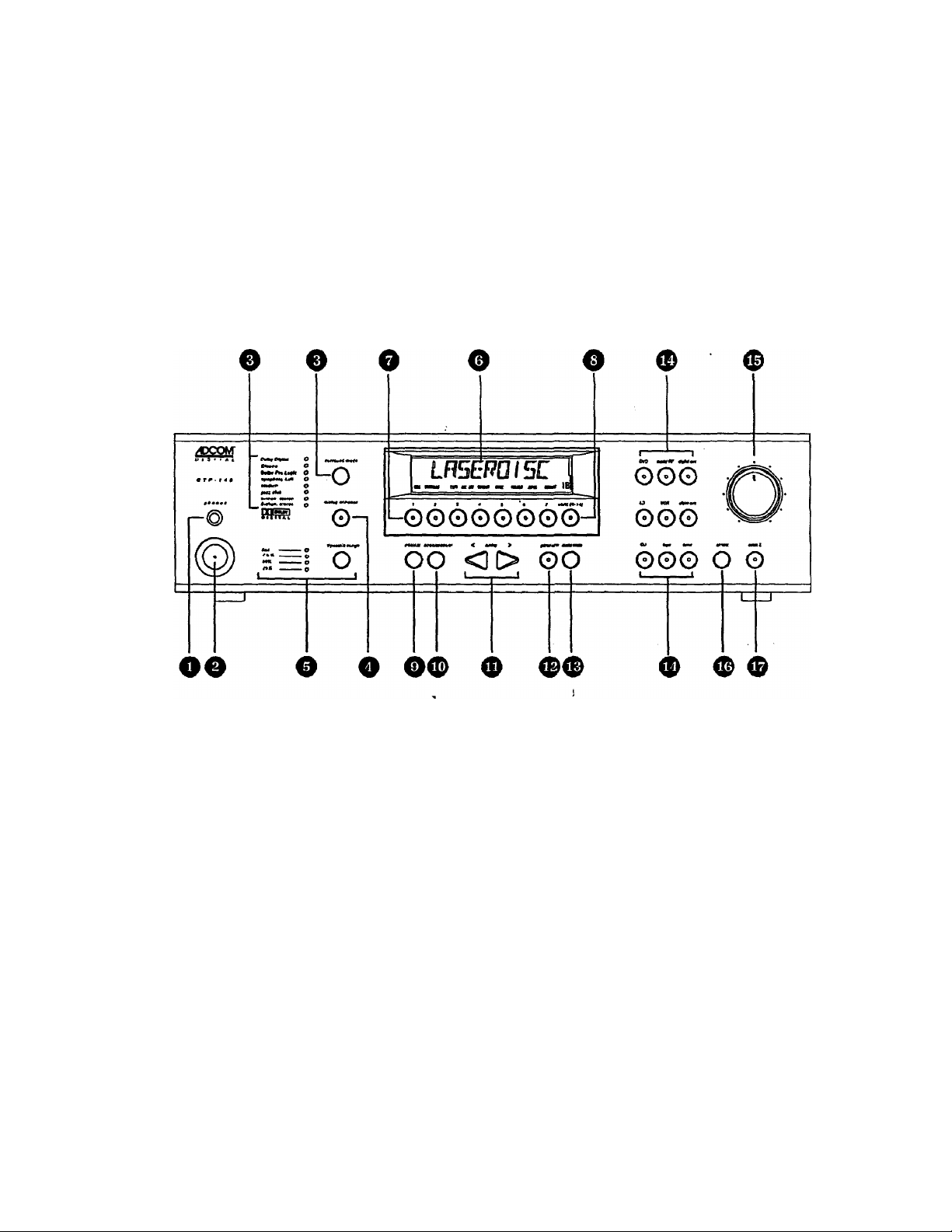
The GTP-740's front panel is a study in simplicity as all controls are logically grouped for intuitive
operafion. Look at the following diagram and read the short explanations of each feature. When you
finish, you will be well on your way to enjoying the GTP-740’s convenience and sound quality.
1 Headphone jack
2 Power button and LED
3 Surround mode button and LED indicators
4 Dialog Enhance button
5 Dynamic Range button and LED indicators
6 Display Window
7 Tuner preset buttons
8 ShK (8-14) button
9 FM/AM button
10 Seek/Manual button
11 Tuning Down/Up buttons
12 Panel Dim button
13 Audio Mute button
14 Input Selector buttons
15 Master Volume control
16 IR (infrared) sensor
17 Room 2 button
Page 8

Headphone jack: This accepts the stereo 1/4” phone plug connector used by almost all high
quality headphones. When you use the headphone jack, the GTP-740's rear panel main line
level Preamp outputs are muted. Room 2 outputs are unaffected.
Power Button and LED: Use this button to turn your GTP-740 on and off. When you first push
the Power Button to the ON (depressed) position, the center LED will glow yellow until all
circuitry stabilizes. When your GTP-740 is ready to use, the LED will turn red.
NOTE: The front panel Power Button must be engaged to use the remote control. If the front
panel Power Button is not depressed, the remote control will not have any effect. When the front
panel Power Button is engaged, the remote controller’s “Power” button will cycle your GTP-740
between standby and operation modes. When in standby mode (indicated by the yellow LED),
you need to press the remote control’s “Power” button to activate your GTP-740’s circuitry. (The
LED will turn red when you do this.)
Surround Mode button and LED indicators: Pushing the button sequentially steps your GTP740 through all the available operatinig modes linked to the selected input.
For example, if you have chosen the DVD input (a digitai input), the Surround Mode button will
step through Dolby Digital, Dolby Digital/Cinema. and Dolby Digital/2-chan. stereo. The LED
immediately to the right of the selected Operating Mode will indicate the current choice. The
Operating Mode button will automatically bypass choices not applicable to the DVD input.
In a similar manner, the Surround Mode button will step through Dolby Pro Logic/CInemaJDolby
Pro Logic, symphony hall, stadium, jazz club, 5-chan, stereo, and 2-chan, stereo sequentially
when you’ve selected the CD input. Since no CDs can carry a Dolby Digital (AC-3) signal, that
choice is not available.
Dialog Enhance button: A shelving filter with a comer frequency of 7 kHz that reduces the often
excessive high frequencies on some movie soundtracks that make them fatiguing to listen to.
Dynamic Range button and LED indicators: This button, usable only with a Dolby Digital
source, incrementally reduces theaudio track’s dynamic range in four steps (full, 75% , 50%>, and
25%) to allow comfortable listening under a wide variety of conditions. The normal, or default,
position is full.
Although we usually prefer to reproduce a source’s full dynamic range (the difference between
very loud and very soft sounds), we occasionally need to reduce dynamics. For example, when
playing a movie late at night, loud explosions might wake sleeping family members. Simply
turning the volume control down would probably make a whisper in the next scene inaudible. The
Dynamic Range button solves this dilemma by progressively lowering the volume of loud peaks
while increasing the level of softer sounds. This allows you to hear every element of the
soundtrack without disturbing those around you or forcing you to strain to hear delicate nuances.
Display window: This shows all the pertinent information you will need to effectively use the
GTP-740 on a daily basis. We carefully designed this window to display only the data you need at
the time you need it. The window’s configuration will change as you ask the GTP-740 to do
different things. The display normally shows the input you’ve selected. If you’re currently listening
to AM or FM radio, the display shows that signal’s frequency. Additional Information appears as
needed and we’ll note these appearances in subsequent sections of this manual.
Tuner preset buttons: These buttons (and the Shift button: see # 8 immediately below) allow
quick access to up to 14 preselected AM or FM broadcast frequencies.
Page 9

Shift (8-14) button; This allows each of the 7 tuner preset buttons to do “double duty.” When the
LED in the center of the shift button is illuminated red, the 7 tuner preset buttons activate tuner
presets 8-14. When the LED in the center of the shift button is not illuminated, the 7 tuner preset
buttons activate tuner presets 1-7.
FM/AM button; As you might expect, this button selects AM or FM. In addition to the selected
broadcast frequency, a small “AM” or “FM" indicator appears in the bottom of the Display Window
to confirm your choice.
10
11 Tuning DownAJp buttons: These allow easy selection of all the stations your GTP-740 can
12 Panel Dim button; This reduces Display window brightness for listening or viewing in a dark
13 Audio Mute button; This button lowers levels at the main preamplifier outputs by 20 dB. Press
14 input Selector buttons and LED indicators: These allow easy dioice of any available input.
Seek/Manual button: This controls the tuner’s scan function.
In Seek mode (indicated by the word “seek” in the bottom center of the Display window), the tuner
will automatically go to the next active broadcast frequency when you press either of the Tuning
buttons (see #11 immediately below.)
In Manual mode, the tuner will jump to the next higher or next \ower adjacent frequency when you
press either Tuning button, whether or not that frequency is active. For example, if the GTP-740
indicates an FM frequency of 91.1 (MHz) and you press the Tuner Up button, the GTP-740 will
display 91.3, the next available frequency. Similarly, if you’re listening to an AM broadcast at
1630 (kHz) and press the Tuning Down button, you will see 1620.
Note: These frequency intervals apply only to North America. Other countries may be different.
receive. Remember that these Tuning buttons will scan to the next active or to the adjacent
frequency depending on how you’ve set the Seek/Manual button described above.
room. The button simply toggles between full and reduced illumination.
It again to restore previous levels. Audio Mute does not affect “Room 2” outputs.
When you select a particular input, the LED in the center of that button will light and the input
name will appear in the Display window to confirm your choice. Choosing an input automatically
selects the Surround mode last used with that input. You may change frie Surround mode at any
time by using the Surround Mode button (#3 above.)
15 Master Volume control; This rotary knob raises the volume to all active speakers
simultaneously as you turn it clockwise and lowers volume when you turn it counter-clockwise.
16 IR (infrared) sensor: This small window receives invisible infrared commands from the remote
controller. Do not block this window with accessories, cables, CD jewelboxes, etc., or the
remote controller will not work.
17 Room 2 button; Pressing this button will activate the Room 2 output circuitry, enabling any of six
analog audio and video sources; LD, VCR, video aux, CD, tape, and tuner. Pressing the
Room 2 button will cause the LED’s on the available source buttons to illuminate. The source that
is currently selected for room 2 will be flashing. Choose the source you want to send to Room 2
by pressing the desired source button, it wili illuminate steadily and the others will go off.
Page 10

1.2 Rear Panel inputs & Outputs •• System Connections
Like the front panel, the GTP-740’s rear panel is carefully arranged to make hookup,
configuration, and use as simple as possible. However, the GTP-740’s extraordinary capabilities
take some study to use most effectively. We strongly suggest that you read this section of the
manual very carefully before beginning to hook up your system. You will save yourself much time
and effort if you carefully think out what you expect from your system; consider the components
you will use, where they’ll be placed, and how you will want them to work together.
A NOTE ON CABLES
Different connections require different types of cables. For example, normal
analog audio interconnects are not ideal for either digital audio or video signal
transfer.
Coaxial digital audio cables (those with RCA connectors at each end) should
have a characteristic impedance of 75 ohms. Similarly, video cables, both
composite and S-Video, should have, a characteristic impedance of 75 ohms.
One question you will need to answer right away is which video signal format—composite or SVideo—you will be using throughout the system. The GTP-740 will handle either equally well but
will not convert from one to ttie other. In general, the composite format Is more widely used,
although S-Video offers significantly better resolution with more advanced sources, especially
DVD. S-Video’s advantages decline somewhat with long cable runs. You may want to confer
with your ADCOM dealer before deciding on one or the other.
Composite or S-Video?
The GTP-740 is shipped from the factory preset for use with composite video sources and display
devices. While set for composite video use, the GTP-740’s on-screen menu is not available at either SVideo monitor output.
If you elect to use S-Video connections, you must set the GTP-740 for this format. You can do this by Using
the menu system (see Section 3 for details), or you can follow these three steps:
1) Turn the GTP-740 off via the front panel power switch. (Do NOT use the remote controller’s “power”
button.) (When the unit is fully off, the LED in the center of the power switch will NOT light.)
2) Hold the surround mode button down
3) While continuing to hold the surround mode button down, press the front panel power switch again to
activate the GTP-740.
This will switch the GTP-740 from standard (composite) to S-Video mode. For verification, hook your
display device to either S-Video “monitor out” (make sure you’ve chosen the S-Video input) and press the
“menu” button on the GTP-740’s remote controller. If the SETUP menu screen appears, the GTP-740 is set
for S-Video operation.
If the SETUP screen does not appear, recheck all connections. This will probably resolve the problem.
However, remember that your dealer may have tested your GTP-740 and already switched it from
composite to S-Video mode.
If this is the case, or if you simply want to reset the GTP-740 for use with composite video components,
follow the three steps immediately above to toggle back to the composite video mode. Make sure your
monitor is connected to a composite “monitor out” and that the monitor is set for the correct composite input.
Press the remote controller’s “menu” button again. You should see the SETUP screen displayed on the
monitor.
Page 11

The diagrams and notes in this section will probably answer most of your questions about interfacing the
GTP-740 with other components in your system. You will find more detailed information on initial setup
and configuration in following sections of the manual.
18
19
20
21
22
Antenna connections
Digital audio/standard (composite) video inputs
DVD
Dig aux
DigRF
Digital RF Demodulator bypass svfHch
12 volt trigger output
Analog audio/standard
(composite) video inputs and outputs
LD (laserdisc) inputs
VCR inputs and outputs
Video aux in
Room 2 outputs
Ball System inputs and outputs
Tape inputs and outputs
Standard (composite) video monitor outputs
CD inputs
23
24
25
26
27
28
29
S-Video inputs and outputs
DVD input
Dig Aux input
Dig RF input
LD Input
VCR input
VCR output
Video aux input
Room 2 output
S-Video monitor outputs
Ball System input and output
Ball System On/Oft switch
Remote control connections
Infrared repeater outputs
IR mini jack (infrared sensor) input
Remote sensor extension outputs
Preamplifier outputs
AC fuse holder
AC power cord
AC convenience outlets
0
10
Page 12
Note that the GTP-740’s RCA-style jacks have color-coded centers to make
connections easier. Use this key to help route cables properly:
YELLOW centers =
BLACK centers
WHITE centers
RED centers
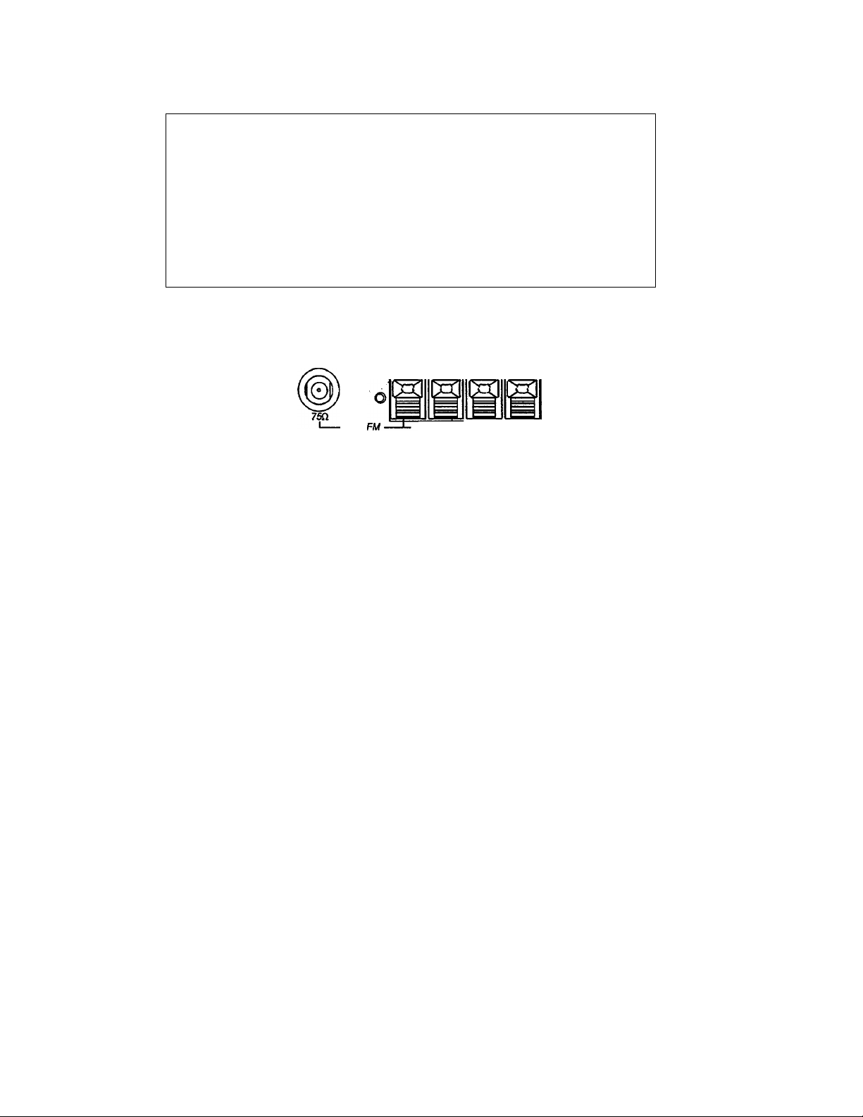
18 Antenna connections: You need to connect different antennas for FM and AM reception.
For FM, use either the 75 ohm “F" connector or the 300 ohm “push terminals” depending on what
type of antenna you’ve chosen. If you’re getting FM from a cable system feed, you will most likely
use the “P connector. The “T" shaped antenna supplied with the GTP-740 uses the push
terminals marked “300 ohms." “T" antennas are directional. They should be placed as high as
possible with the arms fully extended. If possible, the arms should be oriented so that they are at
right angles to the transmitter.
=
=
=
VIDEO signals (composite)
DIGITAL AUDIO signals
and
CENTER CHANNEL and SUBWOOFER
PREAMP outputs
LEFT CHANNEL ANALOG AUDIO signals
RIGHT CHANNEL ANALOG AUDIO signals
antenna
300a-t ground AM
signal direction
t
transmitter
signal direction
t
best reception
FM antenna
The supplied AM loop antenna connects to the push terminals marked “ground” and “AM,”
respectively. You may need to adjust the position of the antenna for best reception. If you use an
outdoor AM antenna, follow the manufacturer’s instructions.
poor reception
to GTP-740 FM
antenna connections
M.
11
transmitter
Page 13
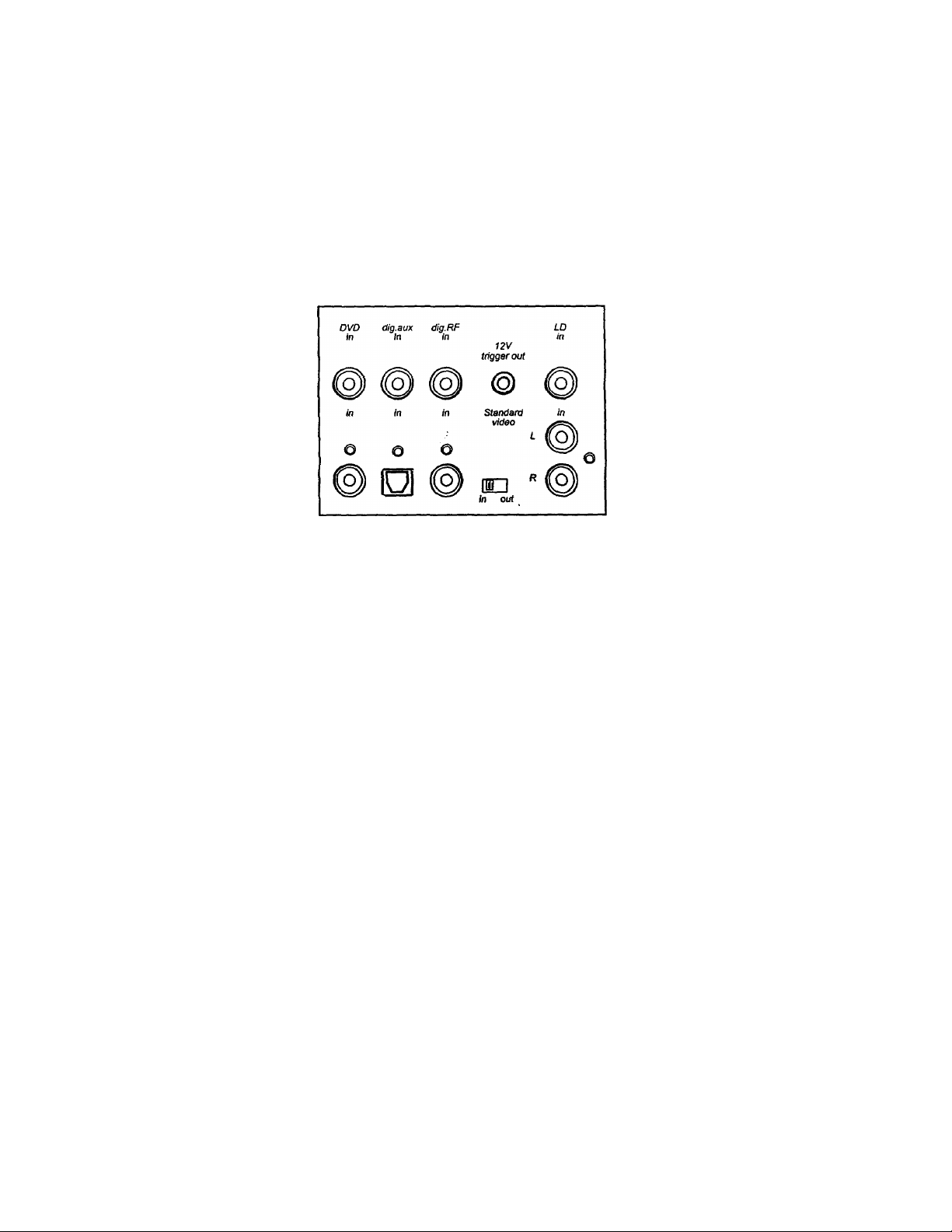
19 Digital audio/standard (composite) video inputs
Remember that you must choose either standard (composite) or S-Video
connections before hooking up source components. This section of the manual
assumes you have chosen composite connections. S-Video connections will be
handled in a subsequent section.
DVD in: Connect the DVD player’s composite video output to the yellow-center RCA jack
immediately under the “DVD in” label.
Connect the DVD player's RCA-style digital output jack to the GTP-740’s black-center
RCA jack located under the “DVD in" label.
_________
Note: If your DVD player has only a TOSlink (optical) digital output, you may need to
connect it to “dig. aux in." If this is the case, remember to connect the player’s video
output (composite or S-Video) to the appropriate “dig. aux in" jack.
Dig Aux In; This Input is recommended for an audio/video source (DSS receiver, etc.) with a
TOSlink (optical) digital output.
Remember that the composite video connection will go to the yellow-center RCA jack
immediately under the "dig. aux in" label.
Connect the source’s TOSlink (optical) digital output to the GTP-740’s TOSlink socket
located under the "dig. aux in" label.
Dig RF in: We recommend this input for laserdisc players with a digital RF output. It is the only
input on the GTP-740 equipped with the RF demodulator needed to process a laserdisc’s
Dolby Digital encoded soundtrack.
Connections follow the same pattern detailed in “DVD in" and “Dig. aux in” above.
Connect the laserdisc player’s composite video output to the yellow-center RCA jack
immediately under the “dig. RF” label, then connect the player’s coaxial digital output to
the black-center RCA jack under the “dig. RF in” label.
12
Page 14
20 Digital RF Demodulator bypass switch
(see illustration on preceding page)
This switch adds flexibility to the GTP-740. If you play laserdiscs with Dolby Digital-encoded
soundtracks, put this switch in the IN position. This places the demodulator circuit in the signal
path and allows proper Dolby Digital decoding.
If you do not have a laserdisc player with a digital RF output, place the switch in the OUT position.
You can then use this input in exactly the same way as you would use the DVD input.
21 12 volt trigger output
(see illustration on preceding page)
To facilitate remote turn-on and turn-off of other components (power amplifiers, for example), this
2.5 mm mini-jack provides a constant signal (12 volts DC) whenever the GTP-740 is fully
powered. When the GTP-740 is turned off (via the front panel switch) or placed in standby mode
(via the “power” button on the remote controller), the jack has no output.
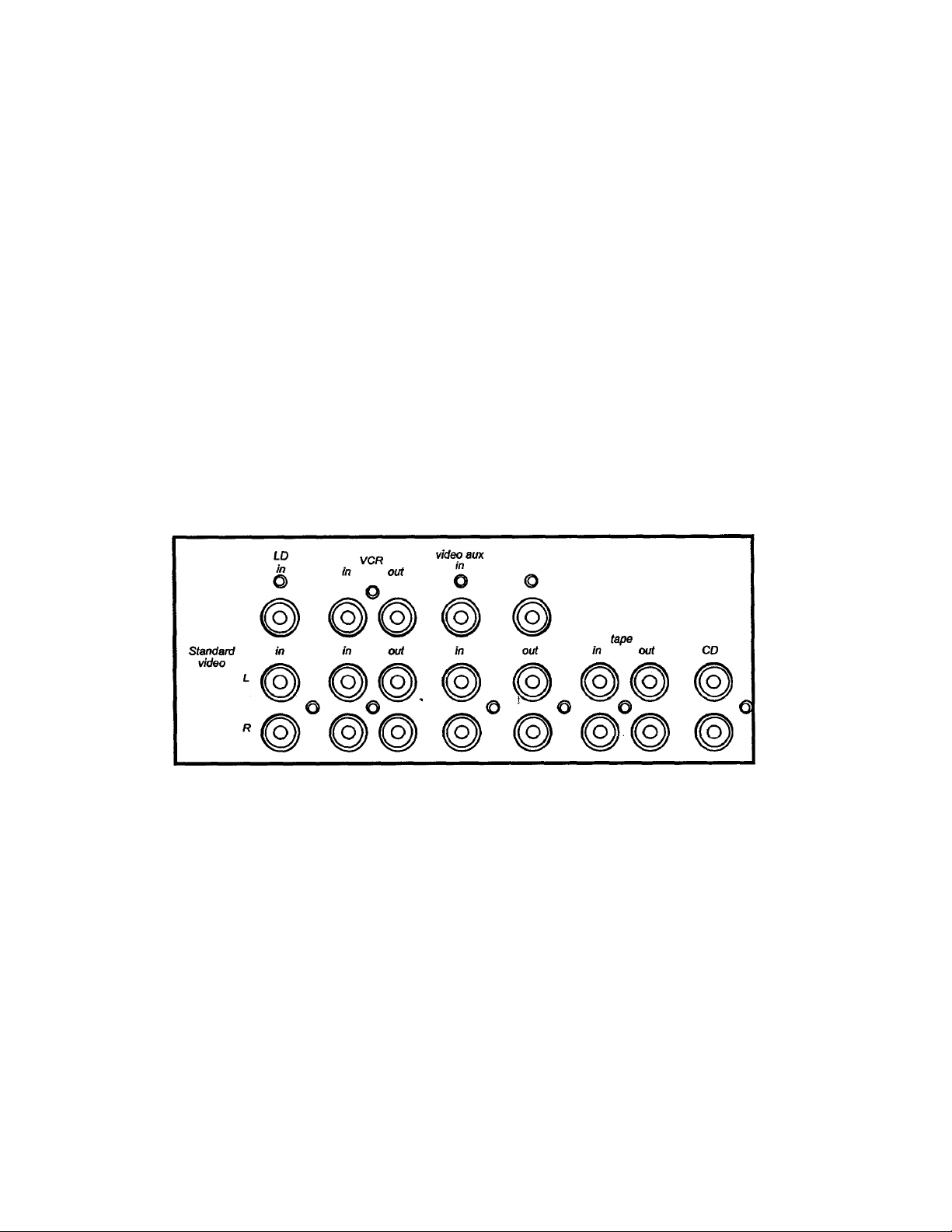
22 Analog Audio and Standard (Composite) Video inputs and outputs
LD (laserdisc) inputs:
Use these inputs as you have already used the digital source inputs (see #19 above.)
After selecting and connecting the laserdisc player’s composite video output to the GTP740’s yellow-center RCA jack immediately under the “LD in" label, connect the player’s
left channel analog audio output to the white RCA jack under the “LD In” label. Then
connect the player’s right channel analog audio output to the “LD in" red RCA jack.
13
Page 15
VCR inputs and outputs;
(see illustration on preceding page)
Because you will use your VCR to record as well as play, take care to follow these
instructions carefully.
1) Connect the VCR’s composite video output to the GTP-740's yellow-center RCA jack
immediately under the “VCR in" label.
2) Connect the VCR’s composite video input to the GTP-740's yellow-center RCA jack
immediately under the “VCR out” label.
3) Connect the VCR’s left channel analog audio output to the GTP-740's white “VCR in"
jack.
4) Connect the VCR’s right channel analog audio output to the red “VCR in" jack.
5) Connect the VCR’s left channel analog audio input to the GTP-740’s white "VCR out”
jack.
6) Connect the VCR’s right channel analog audio input to the red “VCR out” jack.
Note: You may want to use so-called “AA/ combination" patch cords to make this step
less confusing. Sold under a variety of names, these combination cables usually include
a video conductor and two audio conductors in one cable assembly. If you elect to use
them, make sure that they support the video format (composite or S-Video) you’ve
chosen for your system.
Video aux input:
(see illustration on preceding page)
This input is electrically identical to the LD input described above and will accommodate a
wide variety of audio/video sources.
After selecting and connecting the source’s composite or S-Video output to the GTP-740’s
corresponding “video aux" video input, connect the source’s left channel analog audio
output to the white RCA jack under the “video aux in" label. Then connect the SQurce’s
right channel analog audio output to the red RCA jack under the “video aux in" label.
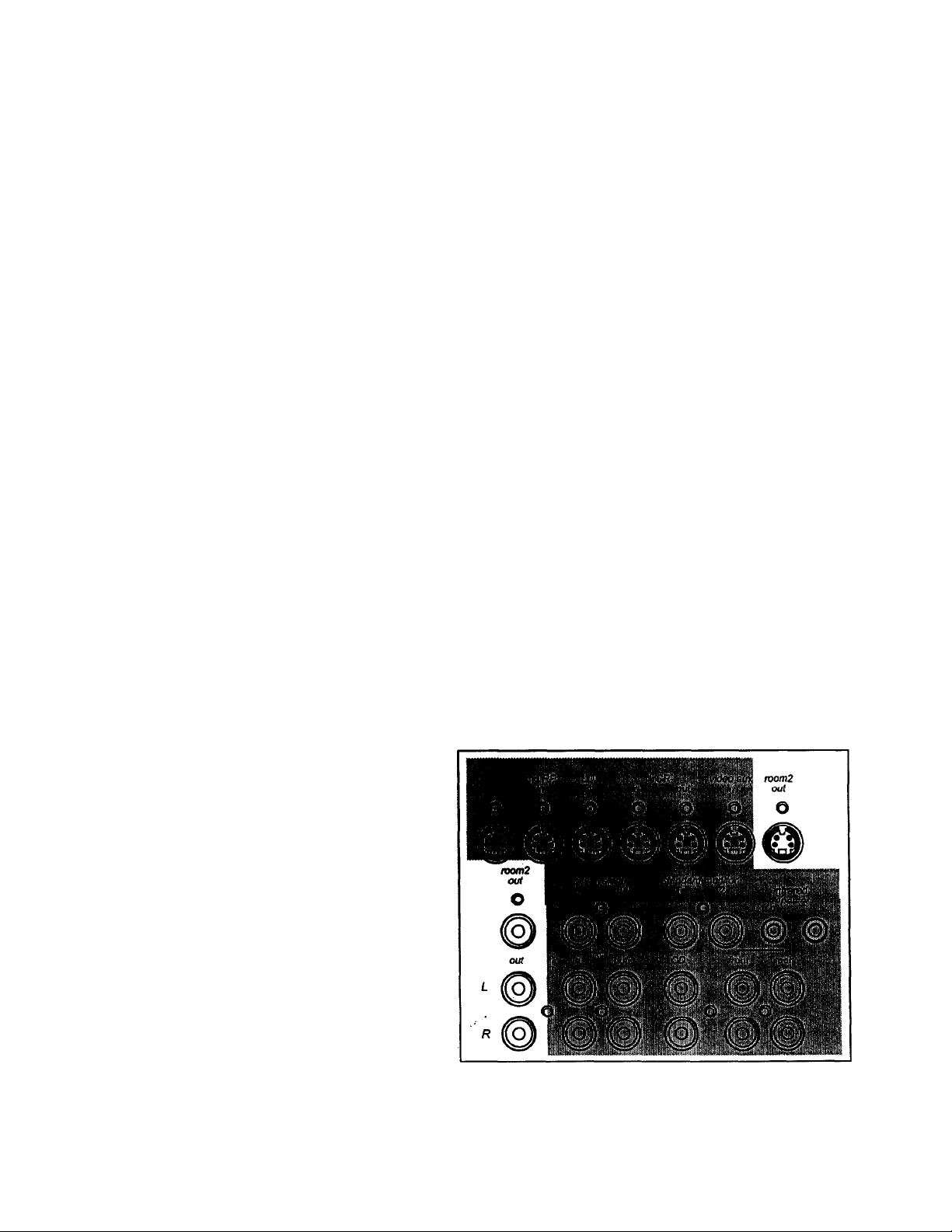
Room 2 outputs:
These outputs supply video
and audio signals for
distribution to a secondary
area or room in your home.
Room 2 features are
covered in a separate
section of this manual.
Connect the composite
Room 2 video output to the
video display device (TV or
video projector) in the
remote area. Make sure the
cable(s) you use for this
connection are high quality
and well shielded as long
cable runs act as antennas
for unwanted interference signals. (Depending on the distance between the GTP-740 and
the display device and, to a lesser extent, the video format you’ve chosen, you may need
14
Page 16

a video distribution amplifier to make sure the signal arrives at the display device properly.
Consult your ACCOM dealer for additional information if needed.)
Connect the white “Room 2 ouf jack to the left channel input of the amplifier used to
power speakers in the remote area. Then connect the red “Room 2 out” jack to the
amplifier’s right channel input.
Ball System inputs and outputs:
These connections allow easy interface with ACCOM’s unique “Ball System,” the BOS500 home theater controller. Note that the BOS-500 processes video signals only so you
don’t need to concern yourself with any audio connections between it and the GTP-740.
(For additional information, consult the BOS-500 manual.)
Connect the BOS-500’s composite video output to the GTP-740’s
yellow-center “Ball System in" jack. Then connect the BOS-500’s
composite input to the GTP-740’s yellow-center “Ball System ouf
jack.
If you are using the GTP-740 with the Ball System, make sure you’ve
set the Ball System switch correctly.
Tape inputs and outputs:
These connections are designed for a cassette
deck or any other audio recording device with linelevel analog inputs and outputs.
Follow these instructions;
1) Connect the recorder’s left channel analog audio output to the GTP-740’s white “tape
in” jack.
2) Connect the recorder’s right channel analog audio output to the red “tape in” jack.
3) Connect the recorder’s left channel analog audio input to the GTP-740’s white “tape
out” jack.
4) Connect the recorder’s right channel analog audio input to the red “tape out" jack.
15
Page 17

standard (composite) video monitor outputs;
CD inputs:
(see illustration on preceding page)
These line-level analog inputs allow easy connection of a CD player (or other two channel
analog audio source.)
Follow these instructions:
1) Connect the CD player’s left channel analog audio output to the GTP-740’s white
“CD in" jack.
2) Connect the CD player’s right channel analog audio output to the red “CD in” jack.
23 S-Video inputs and outputs
Note: This section assumes that you’ve elected to use S-Video sources and display devices
exclusively and that you've set the GTP-740 for S-VIdeo signal transfer by following the steps
described in the boxed note entitled Composite or S-Video? on page 9.
Connect the main monitor or display device to the yellow-center RCA jack
under the “standard monitor 1” label. You may use the "standard monitor 2”
jack for another monitor if desired. Properly connected, either monitor will
then display an image from a video source or on-screen menu information
when appropriate.
DVD <Sg.»ux <Sg.RF LD
in in in in
video aux moni2
in out
VCR video eux momS
in out in out
S-video monitor
1 2
When hooking up S-Video capable audio/video components, follow the steps outlined in Sections
19 and 22 above. However, ignore the instructions for composite video connections and
substitute the following:
DVD in: Connect the DVD player’s S-VIdeo output to the mini-DIN connector under the S-Video
“DVD in" label.
Dig. aux in: Connect the source’s S-Video output to the mini-DIN connector under the S-Video
“dig. aux in” label.
Dig. RF in: Connect the source’s S-Video output to the mini-DIN connector under the S-Video
“dig. RF in” label.
16
Page 18

LD in; Connect the LD player’s S-Video output to the mini-DIN connector under the S-Video
“LD in” label.
VCR in: Connect the VCR's S-Video output to the mini-DIN connector under the S-Video
“VCR in” label.
VCR out; Connect the VCR’s S-Video input to the mini-DIN connector under the S-Video
“VCR out” label.
Video aux in: Connect the source’s S-Video output to the mini-DIN connector under the S-Video
“video aux in” label.
Room 2 output; Connect the video display device to the S-Video mini-DIN output under the
“room 2 out” label.
S-Video monitor outputs: Connect the main monitor or display device to the mini-DIN jack
under the “S-Video monitor 1" label. You may use the “S-Video monitor 2” Jack for
another monitor if desired. Properiy connected, either monitor will then display an
image from a video source or on-screen menu information when appropriate.
Ball System input and output: Connect the BOS-500's S-Video output to the mini-DIN jack
immediately under the “ball sys in" label. Then connect the BOS-500’s S-Video input to
the mini-DIN jack under the “ball sys ouf label.
24 Ball System On/Off switch
This switch controls a “video loop" that enables the GTP-740 to function seamlessly with
ADCOM’s Ball System controller.
25
For conventional high performance home theater systems, make sure the “ball sys on/off switch
is in the off position. When using the Ball System controller, place this switch in the on position.
Remote control connections
remote sensor
Infrared
repeater
IR
mini lack
extension
© © ©
Infrared repeater: These mini-jack outputs transfer command codes received from either the IR
mini-jack or remote sensor extension inputs to an IR repeater located close to other
system components. IR signals received at the GTP-740’s front panel IR receptor are
NOT available at the infrared repeater outputs.
IR mini-jack: This input receives IR command codes from remote sensors.
Remote sensor extension inputs: These inputs receive signals from ADCOM’s XR500II and
SPM500II remote control sensors.
17
Page 19

26 Preamplifier outputs
27
These are the GTP-740’a main outputs,
channel as follows;
1) Connect the white-center RCA output marked “front L(eft)" to the amplifier channel
designated for the left front loudspeaker.
2) Connect the red-center RCA output marked “front R(ight)" to the amplifier input
designated for the right front loudspeaker.
3) Connect the white-center RCA output marked “rear L(eft)” to the amplifier input
designated for the left rear loudspeiaker.
4) Connect the red-center RCA output marked “rear R(ight)” to the amplifier input
designated for the right rear loudspeaker.
5) Connect the black-center RCA output marked “center" to the amplifier input
designated for the center channel loudspeaker.
6) Connect the black-center RCA output marked “subwoofer" to the amplifier input (in
most cases, the line-level input of a powered subwoofer) designated for the
subwoofer.
Note: There are two subwoofer outputs (1 & 2.) They are in parallel (i.e., each produces
an identical signal) and may be used interchangeably. We've included these outputs to
make it easier to add a sepond subwoofer, if desired.
AC fuse holder
This holder provides easy access to the AC line fuse if that fuse needs replacement. To gain
access to the fuse, insert a Phillips head screwdriver and turn counterclockwise. After replacing
the fuse, reseat the holder by turning clockwise until the holder is firmly seated.
Connect each to the proper amplifier or amplifier
When replacing the fuse, ALWAYS use one of equal value (for domestic models use an FSOOmA,
250V fuse available at any electronic parts store.) NEVER use a fuse of higher value. If the fuse
fails again, consult your ACCOM dealer or call the ADCOM Service Department directly.
28 AC power cord (115VAC models)
Make sure to seat this cord firmly in an unswitched wall socket to provide uninterrupted power to
the GTP-740. When removing the cord from an AC socket, NEVER pull on the cord itself.
Instead, grasp the plug firmly and remove it from the socket. You may need to “rock” the plug
lightly for easier removal.
28a AC power cord receptacle (export models)
This I EC-standard socket accepts a wide variety of AC power cords.
18
Page 20

29 AC convenience outlets (115VAC models)
These outlets are for low-current source components only. They are not
designed for power amplifiers.
'“The single unswitched outlet is live whenever the GTP-740 is plugged into a live AC source. The
two switched outlets are live only when the GTP-740 is fully operational (i.e., whenever the front
power button’s LED is red.) They are not live when the GTP-740 is in standby mode (when the
LED is yellow.)
Observe the wattage limitations printed above the two switched and one unswitched outlets. Note
that the 500VA figure (equivalent to 500 watts) above the two switched outlets is a maximum
figure for both outlets combined. Do not exceed this limit.
We strongly recommend the use of our switched power line conditioner, the ADCOM ACE515, for systems with substantial amplifiers and many source components. In addition to
relieving the GTP-740 from handling large current surges, the ACE-515 protects your entire
system by filtering and conditioning the AC current. In addition to numerous heavy duty
AC outlets, the ACE-515 includes sequential power-up and power-down modes to minimize
“thumps” whenever you turn your system on or off.
_____________________________________
19
Page 21

1.3 The Remote Control
30 Source selectors
main
DVD
*-VCR
tuner
V. aux (Video auxiliary)
CD
d. RF (digital RF) ~ digital LD
d. aux (digital auxiliary)
31 Power
32 Input selectors
33 Volume Up/Down
34 Tuning Up/Down
35 Guide
36 Menu
37 < (left arrow)
38 Up arrow/Pause
39 > (right arrow)
40 Down arrow/Stop
41 Select/Play
42 Direct access keypad
(“1" through “10” and “+10”)
43 Shift
44 FM/AM
45 Stereo
46 Srnd (surround)
47 Enter
48 d. (dynamic) range
49 dialog
50 Level trim
Rear Up/Down
Center Up/Down
Sub Up/Down
51 Bal. chk (balance check)
52 Dim
53 Ml, M2. M3. M4 (Macro keys)
54 Room 2
55 Backlight
56 Mute
■ [ I power |1
tlune^
digital LD
IC®] GH
The ADCOM universal remote controller is preset
to operate most GTP-740 functions (MAIN device
mode), GTP-740 AM/FM tuner functions (TUNER
device mode) and GCD-700/750 CD functions (CD
device mode.)
20
^
Page 22

30 Source selectors (main, DVD, VCR, tuner, v. aux, CD, d. RF, d. aux.)
These buttons serve two functions.
First, they switch inputs on the GTP-740 so you can hear the source you’ve just selected.
Second (and even more important), they can change the functions of all the other buttons on
the remote controller. In other words, if you first push the DVD device selector, the remote's
select/play button generates a command code for your DVD player. If you then press the d.
aux device selector, the same select/play button would send a different command code that
might, for example, start your mini-disc player. (Of course, this all depends on how you
programmed the remote in the first place. Don’t worry—we’ll cover that shortly.)
31
32 Input selectors (tape, LO)
33 Volume Up/Down
34 Tuning Up/Down
35
Power
• In main mode (after you’ve pressed the main device selector), this is preprogrammed to turn
the GTP-740 on and off.
In tuner mode, it is also preprogrammed to turn the GTP-740 on and off.
The button is programmable for use with other sources.
In main mode, these are similar to the source selectors described above but they switch only
GTP-740 inputs. They DO NOT automatically change the functions of other remote buttons.
These buttons are programmable for use with other sources.
In main mode, these buttons are preprogrammed to raise and lower the GTP-740’s master
volume level accordingly.
They are programmable for use with other sources.
In tuner mode, these buttons‘are preprogrammed to scan up or down the GTP-704’s AM or
FM band.
They are programmable for use with other sources.
Guide
36
37
This is intended for easy call-up of cable or satellite program guides.
Button is programmable for use with any source.
Menu
In main mode, this is preprogrammed to call up the GTP-740’s SETUP menu system. (A
subsequent push will exit the menu, regardless of wrtiich menu screen you are in.)
It is programmable for use with any source.
(left arrow)
In main mode, this is preprogrammed to step through the various choices you might wish to
select while a menu item is highlighted.
In CD mode, it is preprogrammed for audible reverse scan with an ADCOM CD player
The button is programmable for use with any other source.
21
Page 23

38 Up arrow/Pause
• In main mode, this is preprogrammed to scroll up to the next choice on a menu screen.
• In CD mode, it is preprogrammed to pause an ADCOM CD player.
• In tuner mode, it is preprogrammed to start scanning preset frequencies higher than the
current station.
• The button is programmable for use with any other source.
39 > (right arrow)
• In main mode, this is preprogrammed to step through the various choices you might wish to
select while a menu item is highlighted.
• In CD mode, it is preprogrammed for audible forward scan with an ADCOM CD player
• The button is programmable for use with any other source.
40 Down arrow/Stop
In main mode, this is preprogrammed to scroll down to the next choice on a menu screen.
In CD mode, it is preprogrammed to stop an ADCOM CD player.
In tuner mode, it is preprogrammed to start scanning preset frequencies lower than the
current station.
The button is programmable for use with any other source.
41 Seiect/Play
In main mode, this is preprogrammed to enter a selection chosen via the menu system.
In CD mode, it is preprogrammed to start an ADCOM CD player.
The button is programmable for use with any other source.
42
43
44
45 Stereo
Direct access keypad (buttons “1” through “10,” and “+10”)
• in tuner mode, buttons “1” through “7” are preprogrammed to access preset stations.
• In CD mode, buttons are preprogrammed as track access commands for the ADCOM CD
• The buttons are programmable for use with any other source.
Shift
• In tuner mode, button is preprogrammed to access presets 8 through 14 (“Shift” + “2" =
• In CD mode, button is preprogrammed as “call” command for ADCOM CD player.
• The button Is programmable for use with any other source.
FM/AM
• In tuner mode, button is preprogrammed to switch between FM and AM bands.
• In CD mode, button is preprogrammed as “repeat” command for ADCOM CD player.
• The button is programmable for use with any other source.
player.
preset number 9, etc.)
In tuner mode, button will change playback from Stereo to Mono.
In CD mode, button is preprogrammed as “program/memory” command for ADCOM CD
player.
The button is programmable for use with any other source.
22
Page 24

46 Srnd (surround)
In main mode, button is preprogrammed to step through GTP-740's various operation modes.
In CD mode, button is preprogrammed to initiate random play with ADCOM CD player.
The button is programmable for use with any other source.
47 ' Enter
• In tuner mode, button is preprogrammed to select “manual” or “seek” tuning modes.
• In CD mode, button is preprogrammed as “time” command for ADCOM CD player.
• The button is programmable for use with any other source.
48 d. (dynamic) range
• In main mode, button is preprogrammed to adjust dynamic range of Dolby Digital encoded
sources.
• In CD mode, button is preprogrammed to access disc 1 with ADCOM CD player.
• The button is programmable for use with any other source.
49 dialog
• In main mode, button is preprogrammed to call up or cancel “dialog enhance” equalization.
• In CD mode, button is preprogrammed to begin and end “A-B" repeat with ADCOM CD player.
• The button is programmable for use with any other source.
50 Level trim (Rear Up/Down, Center Up/Dowm, Sub Up/Down)
Rear Up
• In main mode, button is preprogrammed to increase both rear speaker levels simultaneously.
• In CD mode, button is preprogrammed to access disc 2 with ADCOM disc player.
• The button is programmable for use with any other source.
Rear Down
• In main mode, button is preprogrammed to decrease both rear speaker levels simultaneously.
• In CD mode, button is preprogrammed to clear “repeaf command with ADCOM disc player.
• The button is programmable for use with any other source.
Center Up
• In main mode, button is preprogrammed to increase center channel speaker level.
• in CD mode, button is preprogrammed to access disc 3 with ADCOM disc player.
• The button is programmable for use with any other source.
Center Down
• In main mode, button is preprogrammed to decrease center channel speaker level.
• The button is programmable for use with any other source.
23
Page 25

Sub Up
• In mam mode, button is preprogrammed to increase subwoofer level.
• In CD mode, button is preprogrammed to access disc 4 with ADCOM disc player.
• The button is programmable for use with any other source.
.*Sub Down
• In main mode, button is preprogrammed to decrease subwoofer level.
• The button is programmable for use with any other source.
51
52
53
Bal. chk (balance check)
• In main mode, button is preprogrammed to initiate balance check procedure with test tone
and BALANCE CHECK menu screens.
• In CD mode, button is preprogrammed to access disc 5/Memory Clear with ADCOM disc
player.
• The button is programmable for use with any other source.
Dim
In main and tuner modes, button is preprogrammed to dim GTP-740’s information display.
The button is programmable for use with any other source.
Ml, M2, M3, M4 (Macro keys)
Ml
• In main mode, button is preprogrammed to select Tape 2 input (not applicable to GTP-740.)
• The button is programmable for use with any other source.
M2
• In main mode, button is preprogrammed to select Video 4 input (not applicable to GTP-740.)
• The button is programmable for use with any other source.
M3 and M4
54
55
56
• These buttons are programmable for use with any source.
Room 2
• In main mode, button is preprogrammed to select a Room 2 source.
• The button is programmable for use with any other source.
Backlight
• No programming capabilities. Button backlights all keys for eight (8) seconds when pressed.
Mute
• In main, tuner, and CD modes, button is preprogrammed to mute outputs of device.
• The button is programmable for use with any other source.
24
Page 26

Remote Function Table
This table supplements the information you’ve just read. Use it to quickly review button functions. The
controller’s capabilities are extensive and you may be somewhat intimidating at first. However, you will
soon find that its logical button arrangement and programming capabilities will greatly increase your
enjoyment as you discover the ease with which you can operate your entire system from just one remote!
Look down the left-hand column until you see the button you want to learn about. Then look under MAIN
to see if it is preprogrammed for a GTP-740 function, under CD to see what CD commands are
preprogrammed, and under TUNER to see all preprogrammed tuning functions.
BUTTON
FUNCTION
Main CD
MAIN
Selects MAIN
DVD Selects DVD None None
VCR Selects VCR Nòne None
TUNER
Selects TUNER in None None
V.AUX Selects VIDEO AUX None None
CD Selects CD
D. RF
D. AUX
POWER
TUNING +
TUNING -
VOLUME +
Selects DIGITAL RF None None
Selects DIGITAL AUX None None
Power On/Off & Macro
Not programmable
Not programmable
Master volume up
None
Programmable
None
Power On/Off
Disc Skip + Tuning +
Disc Skip - Tuning Volume up
Master volume
up
VOLUME -
Master volume down
Volume-
Master volume
down
TAPE
LD
GUIDE
MENU
EXIT
DELAY
Selects TAPE
Selects LD
Not programmable
On-screen display
Not programmable
Sets rear chan, delay
Programmable Programmable
Programmable Programmable Programmable
'Track reverse
Track forward
Polarity
Open/close
Programmable
Programmable
Programmable
Programmable
drawer
UP/PAUSE
DOWN/STOP OSD scroll down
<
>
SELECT/
OSD scroll up Pause
Stop Preset Scan -
OSD left select
Search reverse
OSD rioht select Search forward
OSD “Enter" command
Play
Preset Scan +
Programmable
Programmable
Programmable
PLAY
1
2
3
4
5
6
7
8
9
0
Not programmable
Not programmable
Not programmable
Not programmable
Not programmable
Not programmable
Not programmable
Not programmable
Not programmable
Not programmable
Track 1
Track 2
Preset 1
Preset 2
Tracks Preset 3
Track 4
Preset 4
Track 5 Preset 5
Tracks Preset 6
Track 7
Track 8
Track 9
Track 10
Preset 7
Programmable
Programmable
Programmable
Tuner
All Others
None
None
None
None
None
None
None
Programmable
Programmable
Programmable
Programmable
Programmable
Programmable
Programmable
Programmable
Programmable
Programmable
Programmable
Programmable
Programmable
Programmable
Programmable
Programmable
Programmable
Programmable
Programmable
Programmable
Programmable
Programmable
Programmable
Programmable
Programmable
25
Page 27

+ 10
SHIFT
FM/AM
STEREO
SRND
ENTER
D. RANGE
REAR +
CENTER +
SUB +
BAL. CHK
DIALOG
REARCENTER SUBDIM
Not programmable
Not programmable
Not programmable
Stereo mode select
Surround mode select
Not programmable
Dynamic range adjust Disc 1
Rear level up
Center level up
Subwoofer level up Disc 4
Balance check Disc 5/
Dialog enhance on/off
Rear level down
Center level down
Subwoofer level down
Dim display
Ml For Macro use
M2
M3
M4
ROOM 2
MUTE
For Macro use For Macro use For Macro use
For Macro use For Macro use For Macro use
For Macro use
Room 2 source select
Mute volume Mute volume
+ 10
Call
Repeat
Program/Mem.
Random play
Time display
Disc 2
Disc 3
Programmable
Presets 8-14
FM or AM select
Stereo/Mono
Programmable
Seek/Manual
Programmable Programmable
Programmable
Programmable Programmable
Programmable Programmable
Programmable Programmable
Memory clear
A-B repeat
Clear repeat
Programmable
Programmable
Programmable
Programmable Programmable
Programmable Programmable
Programmable Programmable
Programmable. Programmable
Dim Display
For Macro use For Macro use
For Macro use
Programmable
For Macro use
Programmable
Mute volume
Programmable
Programmable
Programmable
Programmable
Programmable
Programmable
Programmable
Programmable
For Macro use
For Macro use
For Macro use
For Macro use
Programmable
ProgrammaUe
PROGRAMMING YOUR ADCOM REMOTE CONTROLLER
Introduction
The ADCOM universal remote controller operates eight different audio/video components. As you’ve
already seen, it’s preprogrammed to control ACCOM’s GTP-740 Preamp/Tuner and the GCD-700 CD
player. In ¿ddition, K has five “component 'memory banks” available so you can program the remote to
learn commands for your DVD player, satellite box, laserdisc player, VCR, etc. This lets you use one
remote controller for your entire system.
Using Preprogrammed Commands
Using the remote controller’s preprogrammed commands is simple. For most GTP-740 functions (volume
up/down, changing surround modes, etc.), follow these easy steps.
1.
Press the main source selector button. This tells the remote that you want to use GTP-740
preprogrammed commands. The main button will flash red to tell you it understands.
2.
Press the appropriate function button (volume up, volume down, etc..) If you’ve selected a button
that actually triggers a GTP-740 command, the main button will again flash red to confirm your choice.
If the main button does not flash, you’ve selected a function button that isn’t preprogrammed.
(Review the table above to see which buttons are preprogrammed.)
26
Page 28

For tuner functions (changing stations, etc.):
1. Press the tuner source selector button. It will flash red.
2. Press the tuning up (or tuning down) function button to change stations. The tuner source selector
wfil flash red to confirm that the function button you’ve selected actually triggers a command. (Again,
use the table to see which buttons are preprogrammed.)
Press the CD source selector first to access preprogrammed commands for ADCOM CD players.
Note: You can program new commands over the preprogrammed commands in tuner and CD if you wish.
However, you cannot program any buttons, even those unprogrammed with GTP-740 command codes,
while you're in main mode. This safety feature assures you that you will always be able to fully enjoy the
GTP-740*s capabilities._______________________________________________________________________
Programming Your Own Commands
You can supplement preprogrammed commands with commands to operate other components. Before
you begin to follow these steps, note the status LED located at the top left comer Just above the remote’s
button panel: It will flash red, orange, or green to signal particular functions as you enter new commands
into your ADCOM remote.
Begin by dedding which source component’s commands you will be transferring to the ADCOM remote.
Then press the appropriate source selector button. For example, if you’re teaching your ADCOM remote
commands for your DVD player, press the DVD source selector first. You can “teach” your remote new
commands for any function button (except backlight) after you’ve selected DVD, VCR, TUNER, V.AUX,
CD,D.RForD.AUX.
1. Place the source component’s remote “head to head” with the ADCOM remote. They should be in line
with each other about 2 to 3 inches apart.
2. Press the ADCOM remote’s appropriate source selector and select/play buttons simultaneously.
Hold both buttons until the statuì LED turns orange and the source selector button glows red. Both
indicators should remain lit.
3. Decide which function button on the ADCOM remote you want to learn a new command. Press it.
The orange status LED will begin to flash and the source selector LED will go out.
4. Find the corresponding button on the source component’s remote. Press and hold it until the status
LED on the ADCOM remote flashes green once and remains green until the button on the source
remote is released. Once the button on the source remote is released, the status LED will start
flashing orange again.
5. Verify that the ADCOM remote has learned the new command by pressing and holding the same
button on the source remote. The ADCOM remote’s status LED should flash green twice and then
go back to steady orange. This indicates successful programming. Release the button on the source
remote.
Repeat Steps 2 through 5 for any other commands you want to teach your ADCOM remote for
that source component.
Save the commands you’ve just programmed into the ADCOM remote by pressing and holding the
appropriate source selector and select/play buttons simultaneously. Hold until the status LED and
source selector LED flash twice and then go out. Repeat these steps for any other source commands
you wish to program.
27
Page 29

Deleting (clearing) Individual Programmed Commands
1. Press the ADCOM remote’s source selector and select/piay buttons simultaneously and hold until
the orange status LED and the source selector button glow steadily.
2. Press the function button you wish to clear. The status LED will flash continuously.
3. Press the backlight button. The status LED will then flash green twice and then revert to steady
orange. The source selector button will continue to glow.
Repeat steps 2 and 3 for any other command you wish to delete for the same source component.
4. Exit “delete mode” by pressing and holding the source selector and select/play buttons
simultaneously. The orange status LED and the source selector button will turn off.
Deleting all the Programmed Commands for one Source Component
1. Press the ADCOM remote’s source selector and select/play buttons simultaneously and hold until
the orange Status LED and the source selector button turn on and remain lit.
2. Press and hold down the backlight button. The red Status LED and the Device button will flash five
times, the Status LED will then flash green twice and turn to a constant orange, indicating that all the
learned information for the device mode selected has been erased.
3. To exit this feature, press and hold the ADCOM remote’s source selector and select/piay buttons
simultaneously. The orange status LED and the source selector button will flash twice and then turn
off.
Deleting all the Programmed Commands for every Source Component
Note: This procedure erases every programmed command accessed
under the DVD. VCR. TUNER. V.AUX. CD. D.RF and ti.AUX input
selectors. Make sure you really want to do this before foliowing the step
below.
1. Press and hold the CD input selector and the light button simultaneously. The red status LED will
flash twelve times. The status LED will then flash green once, followed by a single orange pulse. M
LEDs will then turn off, indicating that every learned command in the ADCOM remote has been
erased.
Macro Commands
Introduction
“Macro” commands are simply a series of individual commands initiated by pushing just one button. The
ADCOM remote can learn up to 10 individual commands and store them as a single macro.
There are five “macro initiator” buttons on the ADCOM remote: power, m1, m2, m3, and m4. Each
“macro initiator” can store and transmit either of two complete macros, depending on which source
selector is active when you push it.
28
Page 30

For macro programming purposes, think of the source selectors as being in two groups: main, DVD. VCR,
and tuner in Group 1; v. aux, CD, d. RF, and d. aux in Group 2. When you program a “Group 1" macro,
you will start by pushing the main source selector. After you’ve completed and memorized that macro
command series, you can initiate it whenever you’re in main, DVD, VCR, or tuner modes. Similarly, you
will program “Group 2“ macros by pushing v. aux first and can use them whenever the v. aux, CD, d. RF,
or d. aux inputs are active.
For example, if the m1 button is programmed in Group 1 mode to turn on the TV, turn on the audio
receiver, turn on the VCR, and then turn on the satellite receiver, it will perform the same series of
commands whenever the m1 button is pressed IF main, DVD, VCR, or tuner sources are active at the
time you select that macro. If you’ve programmed a Group 2 macro, it will send out an identical command
sequence whenever v. aux, CD, d. RF, or d. aux inputs are active.
Programming Macro Initiator Buttons:
1. Press either the Group 1 or Group 2 source selector button (main or v. aux respectively) and the
mute button simultaneously. Hold both buttons until the red status LED and the input selector
button remain lighted.
2. Press the macro initiator button (power, ml, m2, m3 or m4) you wish to program.
3. Select and press up to 10 buttons you wish to store in the macro. Both source selector and function
buttons count as individual commands. Remember that each maao can hold only up to 10 individual
commands.
4. Press the tuning up button to save the macro. The red status LED and input selector button will
blink twice to confirm programming and then turn off.
Please note:
• To add a power (on/off) command to the macro, use the mute button in place of the power
button.
• The tuning up/down buttons cannot be used in a macro sequence.
Programming main volume “punch through”
This particular macro command is very useful. It allows you to adjust the main volume (volume up,
volume down, and mute) regardless of which source selection is active. In practical terms, this means
that you will be able to adjust the GTP-740’s volume without first pressing main—even if you’re in VCR
mode at the time! Remember that you will need to program the remote individually for each source you
think you will use this “punch through” feature with.
1. Press the appropriate source selector and mute buttons simultaneously and hold until both the red
status LED and source selector button remain lighted.
2. Press the volume up button.
3. Press the main source selector. The red status LED and the source selector button you pressed in
Step 1 will blink twice to confirm successful “punch through” programming and then turn off.
Example; If you wish to have the GTP-740's master volume controls operate in the VCR mode, you would
press the VCR source selector button in Step 1 and the main source selector button in Step 3. If you
want the same convenience while in DVD mode, select DVD in Step 1, etc.
29
Page 31

Reversing main volume “punch through”
You can revert to normal volume control operation by erasing the “punch through” command. Do this by
following these steps:
1. Press the appropriate source selector and mute buttons simultaneously and hold until both the red
status LED and source selector button remain lighted.
2. Press the volume up button.
3. Press the same source selector as you chose in Step 1. The red status LED and the source
selector button will blink twice to confirm that you've erased the “punch through" command.
2.0 JNSTALLING/CONNECTING THE GTP-740
2.1 Placement
Your system components need a stable, vibration-free supporting surface. Your ADCOM dealer will be
pleased to show you many different types of audio/video equipment racks and cabinets. Keep the GTP740 (and other audio/video components) away from moisture and out of direct sunlight.
Bear in mind that the GTP-740's rear panel is the central connecting point for almost every component in
your audio/video system. Leave sufficient room behind the rear panel to accommodate cables, antenna
leads, power cords, etc. We recommend a minimum of 5” of free space behind the GTP-740 for maximum
flexibility.
The GTP-740’s contrd and processing circuitry benefits from several advanced microprocessors. These
devices generate signals that occasionally interfere with other components. To avoid this, place the GTP740 on a separate shelf if at all possible with space above and below frie unit for better isolation. In
addition to providing optimum heat dissipation, this also allows easy access to the rear panel to check
connections or reconfigure your system if you desire.
2.2 Connections ' ,
Section 1.2 above has already provided the information you need to successfully connect all the
audio/video components you will need for a sophisticated home theater system. Your ADCOM dealer wiif
be pleased to assist you should you required detailed answers to more advanced system configuration
questions.
3.0 INITIAL SETUP
What this section is all about...
After connecting all the components in your home theater system to the GTP-740, you will need to spend
some time configuring it to best serve your needs. Although this might seem to be a daunting task at first,
the GTP-740’s on-screen menu system and the following step-by-step instructions will easily guide you
through the process.
Remember, all you’re really doing is telling the GTP-740 what’s connected to it, what it’s connected to. and
some things about your speakers and room. The GTP-740’s advanced microprocessors will digest this
information and adjust its internal circuitry accordingly.
30
Page 32

3.1 What You Will Need
1) Decide which video format (composite or S-Video) you will use. After you’ve made that choice, follow
the instructions in the box titled Composite or S-Video in Section 1.2 to make sure your GTP-740 is
set properly.
2) Connect your monitor to the appropriate “monitor output” on the GTP-740. Turn your monitor on,
verify that it is receiving a signal by pressing the remote controller’s “menu” button. Once you see the
on-screen menu’s main screen, you’re ready.
3) Make sure you have a sound level meter handy if you have access or wish to purchase one.
Although you can calibrate the GTP-740 surprisingly well using your ears alone, we
strongly suggest a sound level meter for greater accuracy. TTie Radio Shack meter
(catalog # 33-2050) is both inexpensive and reasonably precise. Other sound level
meters offering improved accuracy and flexibility are available. In general, we find
meters with digital readouts less satisfactory for calibration work as the continuous
scale of an analog readout gives a more useful picture of sound level variations.
3.2 SETUP Screen (Main menu screen)
In composite video mode, all menu screens will show white copy against a blue
background. The highlighted choirs will show black letters against a light gray
rectangle.
If you’ve selected S-Video mode, all screens will show white copy against a dark
gray background. Highlighted choices show as black copy against a light gray
rectangle.
After you’ve connected your monitor to the GTP-740 and turned both units on, press the remote
controller’s menu button once. The following screen will appear;
SETUP
1 INPUTSETTINGS
2 CHANNEL DELAYS
3 SPEAKER SIZE
4 CHANNEL BALANCE
5 EXIT
This screen is the first step in configuring your GTP-740 to best serve your needs. It provides quick
access to all other menu choices.
Input settings should be highlighted. If it is not, use the remote controller’s Up/Down arrow buttons to
move the cursor to INPUT SETTINGS and press the remote’s Select button.
31
Page 33

3.3 INPUT SETTINGS Screen
This screen shows;
Note that the first five menu items (INPUT through DYNAMIC RANGE) contain additional
information. MODE, DIALOG ENHANCE, AND DYNAMIC RANGE are keyed to the input
identified at the top of the screen and are the default settings for that input. You can change these
settings within limits for later recall but remember that the GTP-740’s *Auto SelecT feature may
override your choices under certain conditions.
• INPUT identifies the input in use when you called up the menu system.
INPUT SETTINGS
INPUT:
VIDEO;
MODE:
DIALOG ENHANCE:
DYNAMIC RANGE:
LEVELS MENU
UNDO CHANGES
DONE
• VIDEO tells you which video mode (composite or S-Video) you’ve already selected.
• MODE indicates the operating mode (stereo. Pro Logic, etc.) currently associated with the
chosen input.
• DIALOG ENHANCE selects a proprietary midrange equalization curve designed to reduce
relative high frequency content of very “brighf sources.
• DYNAMIC RANGE indicates the level of compression currently selected. (Note: This applies
only to digital inputs receiving a Dolby Digital-encoded signal.) Choices are Full, 75%, 50%,
and 25%.
The remaining menu items are:
• LEVELS MENU: This works in conjunction with the CHANNEL BALANCE adjustments (# 4 on
the main SETUP screen) and the circuitry initiated by pressing the “bal. check” button on the
remote controller. Our suggestion is to avoid the LEVELS MENU saeen entirely for the
present other than to make sure that all the indicators are centered. If you need to center the
indicators, use the Up/Down arrow buttons to scroll to the appropriate indicator, and then
center It with the < or > buttons. Once all indicators are in the middle of their respective
scales, scroll down to DONE and press Select to exit to the SETUP screen.
• UNDO CHANGES discards any choices you may have just made, maintains previously
chosen settings, and returns you to the main SETUP screen.
• DONE preserves the changes you’ve just selected for future use and returns you to the main
SETUP screen.
32
Page 34

Highlight INPUT if necessary (the Up/Down arrow buttons) and press either the < (left arrow) or > (right
arrow) buttons to scroll to the input you want to modify. (Wait about 2-3 seconds after pressing < or >.
This gives the GTP-740’s microprocessor array time to reset and check all system parameters.)
When you’ve selected the input, the screen displays the currentiy selected defaults associated with that
input. For example, you might see;
INPUT SETTINGS
INPUT: TUNER
VIDEO; COMPOSITE
MODE: 2 CHANNEL
DIALOG ENHANCE: OFF
DYNAMIC RANGE: N/A
LEVELS MENU
UNDO CHANGES
DONE
This tells you that selecting the TUNER input (from the front panel or remote) will automatically “call up” 2
channel operating mode with dialog enhancement Off. Note that dynamic range adjustment is not
possible.
You may change any parameter by highlighting it with the Up/Down buttons and using < or > to scroll
through the available choices. For example, you can elect one of the following modes as the default for
the TUNER input:
2 channel (stereo)
Cinema EQ (with Dolby Pro Logic)
Dolby Pro Logic (no Cinema EQ)
Hall surround
Stadium surround
Jazz surround
5 channel surround (enhanced stereo)
These choices are not consistent from input to input. Dolby Digital, for instance, is not available when
you’ve selected TUNER, because TUNER is an analog input. In this way, the GTP-740 protects you from
making inappropriate choices
Note: If you change video formats, the menu screen will disappear. Do not panic. Just press
Once you’ve adjusted the default parameters for all inputs to your satisfaction, highlight DONE and press
the Select button, this memorizes your choices and takes you back to the main SETUP screen.
3.4 CHANNEL DELAY Screen
The term “delay” is often misunderstood. Conventional surround sound systems routinely
delay the sound going to the rear channels for a few thousandths of a second (a few
milliseconds - abbreviated “mS”) to enhance the apparent directionality of various effects.
In addition, the GTP-740 allows you to calibrate center channel delay.
either the < or > button to restore the screen.
33
Page 35

Based on a psychoacoustic principle called the “Haas effect,” properly implemented rear
channel delay reduces our “acoustic confusion” about the origin of sounds. Rear channel
delay is particularly important with “matrix” surround decoding (Dolby Pro Logic for
example) because even the best matrix circuits “leak” front channel information to the
surround channels.
Center.channel delay compensates for conditions where the two main speakers and the
center channel speaker are at slightly different distances from the listening/viewing
position.
Although discrete delivery systems like Dolby Digital are not as dependent on precisely
calibrated rear channel delay, the GTP-740 follows proper protocol and shifts rear
channel delay settings automaticaliy as you select Pro Logic or Doiby Digital processing.
This will greatly increase your enjoyment of the enormous variety of surround-encoded •
software available today.
From the SETUP screen, highlight CHANNEL DELAYS and press Enter. You will see the following
screen;
CHANNEL DELAYS
CENTER 0 mS
REAR 0 mS
UNDO CHANGES
DONE
If “N/A” shows to the right of CENTER or REAR, change inputs to DVD (or another input where Dolby
Digital is the default operating mode) by pressing the appropriate button on the GTP-740's front panel or
remote controller.
Highlight CENTER with the Up/Down buttons and then select the proper delay setting with the < or >
buttons.
* '*
34
Page 36

Setting Proper Center Channel Delay
For optimum performance, a single impulse from the front speakers should arrive
at the prime listening position at the same instant. Of course, that requires that
the front speakers are all placed at equal distances from the prime
listening/viewing position (PLP.) This is rarely the case, since the center channel
speaker is usually closer to the PLP than the main left and right speakers. This
would mean that sound from the center speaker would arrive at the PLP before
the impulse from the main left and right speakers and confuse the front
soundfield.
To prevent this from happening, we can delay the center channel signal in the
GTP-740 before it reaches the center channel output. Since sound travels
roughly 1 foot every millisecond (or every thousandth of a second), we can easily
calculate optimum delay by measuring the distance from the main speakers to the
PLP and then comparing that to the distance between the center channel speaker
and the PLP. The difference in these two measurements is the proper delay
setting.
For example, if your main speakers are 15 feet from the PLP and the center
channel speaker is 12 feet, the difference is 3 feet. The corresponding center
channel delay is 3 milliseconds (15-12=3.)
The GTP-740 delays center channel output up to 5 milliseconds and thus
compensates for center channel speakers that are up to 5 feet closer to the PLP
than the main left and right speakers.
In rare system setups, the center channel speaker is actually farther away from
the PLP than the main left and right speakers. In these cases, set the center
channel delay to 0 mS.
Next, adjust rear channel delay time by highlighting REAR with the Up/Down buttons and using < and > to
choose the appropriate setting.
The principle here is the same. Measure the distance from the rear speakers to
the PLP and compare it to the distance you've already measured from the main
left and right speakers to the PLP. Note the difference and use that as your rear
channel delay setting.
For example, if your rear speakers are 9 feet from the PLP, the correct delay
setting would be 6 milliseconds (15-9=6.)
Again, if the rear speakers are farther away from the PLP than the main
speakers, set delay to 0 mS.
When DELAY settings are completed to your satisfaction, highlight DONE and press Select to return to
the SETUP screen.
__________________________________________
Setting Rear Channel Delay
________________________
35
Page 37

3.5 SPEAKER SIZE Screen
In the SETUP screen, highlight SPEAKER SIZE and press Enter.
You will see:
SELECT PRESET should be highlighted. If not, use the Up/Down arrows. The < and > buttons will cycle
through Preset 1, Preset 2, and Preset 3. For the moment, select “1."
Most surround controllers allow only one speaker configuration. This is logical,
since you will rarely switch speakers once your system is installed and calibrated.
However, the GTP-740 provides three presets to ailow you to custom-configure
the same system to optimally reproduce both music and video soundtracks.
SPEAKER SIZE
SELECT PRESET: 1
MAIN: LARGE
CENTER: ON
REARS: ON
SUBWOOFER: ON
UNDO CHANGES
DONE
Why Different Speaker Size Presets?
For example, if you use your system primarily for music reproduction, you might
configure Speaker Size Preset 1 for Targe” main speakers with the rear channels
and subwoofer off. For video viewing, you will probably want rear speakers and
the subwoofer on. Speaker Size Preset 2 gives you №e ability to quickiy choose
tiiis combination when apprq|}riate. We’ve provided Speaker Size Preset 3 for '
your convenience. Use it as you will.____________________________
After selecting the proper Preset, scroil down to MAIN. Use the < and > buttons to select either LARGE or
SMALL. Choose LARGE when your main speakers are full bandwidth designs with good bass capability.
Choose SMALL when your main speakers are smaller *satellite” designs or lack deep bass output. (If
you're not sure what to choose here, your ADCOM dealer will be happy to advise you.)
After you’ve configured your MAIN outputs, scroll to CENTER and choose ON or OFF. For most users,
choose ON if your system has a center channel speaker. However, if you’re configuring a Speaker Size
Preset specifically for two-channel music reproduction, you may want to select OFF.
After you’ve configured your CENTER output, scroll to REAR and choose ON or OFF. For most users,
choose ON if your system has REAR channel speakers. However, if you’re configuring a Speaker Size
Preset specifically for two-channel music reproduction, you may want to select OFF.
Scroll to SUBWOOFER and repeat the process described above: ON activates the GTP-740’s Subwoofer
output, OFF mutes it.
After completing all choices, scroll to DONE and press Enter. This will save the configuration and return
you to the SETUP screen.
_______________
36
Page 38

Remember that UNDO CHANGES allows you to exit the configuration process at any time without
memorizing any changes you might have just made. Scroll to UNDO CHANGES and press Select to
return to the SETUP screen.
Note: You may want to repeat these steps for Preset 2 and Preset 3. Just follow the steps above but
make sure you’ve chosen the proper PRESET prior to choosing a different configuration. If you don’t, the
new choices will overwrite those you’ve previously made.
3.6 CHANNEL BALANCE Screen
Proper system calibration (i.e., adjusting the relative output of all speakers to
compensate for system and placement variations) is an essential step if you wish to
enjoy a movie soundtrack or other multi-channel sound source as the director,
producer, or sound engineer intended.
Channel balancing (or “calibrating") a system simply means adjusting the GTP740’s main outputs to compensate for speaker level differences caused by varying
amplifier sensitivities, speaker efficiencies, and speaker placement—all the possible
variations
except those inherent in the software you will be playing .
The GTP-740 gives you several ways to adjust channel balance.
• The first is with the LEVELS MENU adjustments accessed from the SETUP menu
screen. As weVe already pointed out, we suggest that you not use this initially. It
adjusts levels of the main front (left and right) speakers simultaneously and of both
rear speakers simultaneously. Although this has advantages in certain situations, it
is not ideal here.
• The next is with the CHANNEL BALANCE screen. See below for details.
• Another Is by using the remote controller's bai. chk button. This is the preferred
mediod for initial calibration.
• The last is by using the rear, center, and sub Up/Down buttons on the remote.
These are intended for “on the fl/; corrections for some perceived shortcoming in
the source you're currently enjoying!
Why Do I Need To Balance Channel Output?
From the SETUP screen, select CHANNEL BALANCE with the Up/Down buttons and press Enter.
You will see:
CHANNEL BALANCE
LEFT
+
RIGHT
CENTER REARL REARR -
SUB
+
+
+
+
UNDO CHANGES
DONE
LEFT will be highlighted. The < and > arrow buttons will decrease and increase LEFT channel level
respectively. When you’ve completed this adjustment, scroll to RIGHT and, once again, use the < and >
arrow keys until the RIGHT level is satisfactory. Continue through CENTER, REAR L, REAR R, and SUB.
37
Page 39

When you’re satisfied with the relative levels, scroll to DONE and press Select. This will commit the
changes to memory and exit to the SETUP screen.
NOTE: Although this screen allows individual channel adjustments, it is not ideal
for initial calibration. If you’re using the GTP-740 for the first time, we suggest you use
the remote controller’s bal. chk button to begin the initial calibration. The reason for this
is that the bal. chk procedure turns on the GTP-740’s internal test tone generator and
automatically steps that test tone through all six outputs.
3.7 Using bal. chk
The remote controller’s bal. chk button is the easiest way to calibrate the GTP-740. Once your system is
connected and functioning, press the bal. chk button. You will see the following screen:
BALANCE CHECK
LEFT
CENTER RIGHT
REARR -
REARL -
SUB
UNDO CHANGES
DONE
You will hear a Vaterfall” test tone advancing from speaker to speaker. You will also see the highlight bar
automatically advandng through LEFT, CENTER, RIGHT, etc., in synchronization with the test tone.
Before making any adjustments, place your sound level meter as closely as possible to ear height at your
favorite listening/viewing position. (Most sound level meters have a threaded connection on the bottom for
a camcorder or camera tripod that may help you do this.) The meter should be “free standing;" avoid
putting it close to reflective surfaces (including your own body) as reflected sound waves will reduce
reading accuracy.
When using a sound level meter, set it to "Slow" response (to better average
continuous readings), "C" weighing (the *C" scale is more accurate for the type of
measurement you need to do), and adjust the "range" setting to 80 dB.
Adjust the GTP-740’s master volume control until the sound level meter registers approximately 80 dB as
the test tone cycles through the channels. (Don’t be concerned about variations here—once you’re done
calibrating, they won’t be there any longerl)
+
+
+
+
+
+
_________________
Wait until the test tone cycles to the LEFT speaker and verify that you’ve got an 80 dB reading. (If not,
use the master volume control to increase and decrease the test tone volume as necessary.) When the
test tone cycles to the CENTER speaker, use the remote controller’s < and > arrow buttons to adjust
center channel level until you get an 80 dB reading. (You will notice that the test tone will not cycle to the
RIGHT speaker until you’ve completed adjusting the CENTER output.) Repeat this procedure for every
channel.
38
Page 40

Points to Remember:
• The test tone automatically cycles to the next speaker every three seconds UNLESS
you use the < and > buttons to adjust levels. (You will also notice that pressing some
other buttons on the remote controller will temporarily delay this advance.)
• You will probably need several passes until you've equalized levels. Don't be
concerned about this—it’s normal. Once you’ve brought each channel’s level close to 80
dB, one or two more passes will even things out and ensure precise balancing.___________________
When you’ve completed channel balancing, press the bal. chk button again. Both the test tone and the
BALANCE CHECK screen will disappear and the levels you’ve just selected will be memorized. This
completes the initial level calibration.
4.0 BASIC OPERATION
4.1 The Tuner
Selecting stations
As we have already explained in Section 1.1, using the tuning controls to receive your favorite FM
and AM broadcasts is a simple process.
- 1) Select the tuner input via the front panel (# 14) or remote control (# 30) button. The
information display will show the most recently received broadcast frequency.
2) If the band you want (AM or FM) is already displayed, proceed to step 3) below. If not, push
the FM/AM selector (#9 on the front panel, #44 on the remote) to change to the appropriate
band. .
3) Choose your preferred tuning method (seek or manual) by pressing the front panel
seek/manual button (# 10).
While in “seek” mode, the tuning buttonS’(front panel #11, rempte # 34) will take you to the next
active frequency. In “manual" mode, the tuning buttons wiil step to the next available frequency
even if it is unused.
4) Use the tuning buttons to select the station you wish to listen to.
Programming “preset” stations.
The GTP-740 can memorize up to 14 AM and 14 FM signals for instant recall. Place your favorite
stations in memory by:
1) Select either FM or AM as described above. Note the stations you want to preset. Starting at
the lowest end of the frequency range (88.1 for FM, 520 for AM), tune to the first station you
want to program into memory.
2) Press the preset 1 button (# 7 on the front panel, # 42 on the remote) and hold it for
approximately three (3) seconds. (Remember to push the remote’s tuner source selector
before using the keypad.) When you see “Preset 1” appear in the information display and the
LED in the preset 1 button light, that frequency is memorized.
39
Page 41

3) Tune to the next desired frequency and follow the same instructions but use “Preset 2” to
commit this new broadcast frequency to memory.
4) Continue for all presets up to and including the seventh.
5) Setting presets 8 through 14 require the use of the shift button.
• Select the desired frequency for preset # 8. Press shift and then hold preset button
1 for three seconds. When you see “Preset 8” appear in the information display and
the LED’s in the front panel preset 1 and shift buttons light, that frequency is
memorized.
• Select the frequency for preset # 9. Follow the instructions above but substitute
preset button 2 in place of preset button 1. (Remember that the shift button adds a
“7” to the nominal preset button value. Thus, shift + 2 actually means “Preset 9” and
so on.)
• Continue as above until all 14 presets are used or until you run out of “favorite"
stations, whichever comes first.
6) Select the other broadcast band (AM or FM) and begin programming again. Follow the
instructions above. When you're finished, you’ll be able to listen to any of these favorite
frequencies by pushing just one or two buttons.
Listening to “preset" stations
1) Select tuner and either FM or AM.
2) Press the appropriate preset button (or shift + the preset button for choices higher than
“preset 7”).
3) Enjoy.
t
4.2 Room 2 Operation
Introduction
The GTP-740’s “Room 2” circuitry give you the ability to simultaneously enjoy two different
audio/video sources in two different areas of your home. For instance, you can watch a DVD
movie in the main family room while someone else enjoys a satellite broadcast or CD in the
bedroom.
Full “Room 2" capability requires an infrared sensor and a reliable data link between that sensor
and the GTP-740. Consult you ADCOM dealer for details and assistance if necessary.
Selecting a “Room 2” source
Note: Although you can select a “Room 2” source from the GTP-740’s front panel, you probably
won’t want to do this very often. The preferred, and far more practical, method is via the remote
control link between whatever area of your home you've designed “Room 2” and the GTP-740
1) Press the room 2 button (# 17 on the front panel, #54 on the remote) once. The LED in the
center of the room 2 button will light to tell you that “room 2” capability is on.
40
Page 42

2) Press the room 2 button again. The LED’s in the center of the six front panel analog source
selectors will light to show you that you can route any of those sources to the GTP-740’s
“Room 2” outputs. If one of the six source LED’s blinks, that source is already selected for
room 2 distribution. If no LED blinks, no source is currently selected. {Hole: You cannot
direct a digital source - DVD, digital RF, or digital aux — to the Room 2 outputs.)
3) Choose the source you wish to direct to the room 2 outputs by pushing one of the lighted
source selectors. The LED’s in the other source selectors will go out and the name of the
source you’ve just chosen for room 2 distribution will briefly appear in the information display
window. After five (5) seconds, the display will change to show the room 1 (main) source but
the room 2 LED will still glow, indicating that a room 2 source is now active.
4) You can verify the room 2 source selection any time "room 2” capability is active (i.e., any
time the room 2 LED is illuminated) by simply pressing the room 2 button again. You’ll see
ail six analog source selector LED’s light. The active room 2 source LED will blink and the
name of that source will show in the information display. You’ll have ten (10) seconds to
change the room 2 source by simply pressing any other illuminated source selector.
Setting “Room 2” playback volume
You can change “room 2” volume only by using the remote control. There is no way to adjust
“room 2" playback level from the GTP-740’s front panel alone.
Although you can use the remote to adjust “room 2“ volume while still in the main listening/viewing
area, that does not serve a useful purpose as you wont have an easy way to Judge the remote
location’s volume.
1) Press the remote control's main source selector once. This makes sure the remote is ready
to generate GTP-740 command codes.
2) Press the room 2 button twice to access the room 2 mode.
3) Use the remote control’s volume up/down buttons within ten (10) seconds of pressing room
2. The front panel display will show room 2 level changes as you make them and will then
revert to normal display mode ten (10) seconds after the GTP-740 receives the last volume
adjust command.
Remember that you can construct remote control “macros" to automatically put you in “room 2’
command mode. You should always have a second remote controller in the “room 2" location and
that controller can be easily configured with specific room 2 command streams (those beginning
with a command for main source selection followed by two “room 2" pulses) for easy operation.
4.3 Operating Mode Selection
The GTP-740 features several operating modes — Dolby Digital, Dolby Pro Logic, 5 channel
stereo, several “enhancement” modes, etc. — designed to present music and movie soundtracks
as realistically as possible. In addition, some of these modes add the ability to “custom tailor” the
GTP-740’s spatial presentation to better suit individual tastes.
You’ll need to understand these modes — Dolby Digital, Cinema, Dolby Pro Logic, Symphony
Hall, Stadium, Jazz Club, 5 channel stereo, 2 channel stereo — to get the most out of your GTP-
740.
41
Page 43

However, selecting the proper mode can be difficult, particularly when increasingly popular digital
formats like DVD present an often-bewildering array of soundtrack options. For this reason, the
GTP-740 features automatic mode selection (or “Auto Select”) to analyze digital input signals and
process them properly. (Auto Select works only with digital input signals.)
When you are using other inputs, you will probably need to manually select the proper operating
mode. However, the GTP-740 remembers the mode you’ve most recently used for a particular
input ^nd will automatically restore that mode when you use that input next, software permitting, of
course.
You can change modes with the menu system or with the surround mode button (# 3 on the front
panel or # 46 on the remote) when you wish to.
The GTP-740’s operating modes are:
• Dolby Digital: This mode applies only when you’ve selected one the GTP-740’s three digitalonly sources; DVD, digital RF, or digital aux. Contrary to popular belief, Dolby Digital
does not always imply a discrete 5.1, channel soundtrack. That’s because a Dolby Digitalencoded source may have 6 separate channels of information ... or 4, or 3, or 2, or only
11 This is up to the producers of the software you’re playing. If allowed by the software,
all six channels are active.
• Cinema: Not an actual mode itself, “cinema” is an equalization (“EQ") curve designed to reduce
excessive high frequencies and the consequent harshness sometimes encountered in
movie soundtracks originally mixed strictly for theatrical release. “Cinema” can be used in
conjunction with Dolby Digital or Dolby Pro Logic.
• Dolby Pro Logic: Usable with both analog and PCM (i.e., non-Dolby digital-encoded) digital
sources, this is the surround mode of choice for most videotapes, surround-encoded TV
broadcasts, and many music CDs.
• Symphony Hall: This mode emulates the expansive space of a typical concert hall and is
available for all two-channel sources, analog as well as PCM digital. The subwoofer
channel is nof active in this mode.
• Stadium: Again intended only for analog and PCM digital sources, this mode re-creates the
soundfleld typical of a large outdoor sporting event with long reverberation times and
somewhat rolled-off high frequency response. Again, no subwoofer output.
• Jazz Club: An analog and PCM digital source enhancement, this mode simulates the intimacy
of a very small acoustic space. Again, no subwoofer output.
• 5 channel stereo: This makes full use of a home theater speaker array (except for the
subwoofer) vrhen playing two-channel only (analog or PCM digital) sources. It's ideal for
parties or any other time when you want to get the broadest possible sound distribution
from a non-surround encoded source.
• 2 channel stereo: Obviously, the preferred mode for traditional two-channel listening. This
mode is available for both analog and digital sources. In fact, the GTP-740 may even
“auto switch” to 2 channel stereo mode — even for a Dolby Digital source when it
contains only stereo or mono soundtrack information.
I
42
Page 44

5.0 TROUBLE SHOOTING
Your GTP-740’s circuitry is built around advanced microprocessors. The GTP-740
may exhibit occasional anomalies arising from AC line surges, etc. If you experience
unexpected behavior, or if the GTP-740 “locks up” and does not respond to control
input, reset it by turning front power switch off. (Do not use the remote control’s
“power” button.) Wait 10 seconds and then turn the GTP-740 on. This will reset the
internal control circuitry and solve almost all problems.
SYMPTOM
Power LED does not light
POSSIBLE REASON
AC Power Cord not plugged in
AC Fuse failed
Power LED glows
but no sound
Power amp or source unit is not on
Ball Switch (rear panel) is on
No sound from one channel Connections in rear of amp are loose
Input or Output connector
disconnected or loose
Speaker disconnected
Hum from all speakers
(any volume)
Ground loop present
(difference in ground voltages
between components)
A major appliance, dimmer,
halogen or fluorescent light may be
creating interfereruie
Hum from all speakers
Problem with source unit (CD, etc.)
(increases or decreases with
change in system volume)
Problem wiffi cable connecting that
source to the Tuner/pre-amp
POSSIBLE SOLUTION
Plug in AC Power Cord
Replace AC Fuse
Make sure whole system is on
Put Ball System switch in Off position
Verify all connections on rear of amp
Verify both connections on that channel
Verify connection at speaker
If cable TV is present, see Note 1
If cable TV is not present, see Note 2
Make sure all appliances, dimmers and
suspect lights are off
Try different source to verify
Try different cable to verify
Note 1; Cable TV systems can contribute to ground loop problems which, in turn, cause “hum.” To determine whether your cable system is
the contributing factor, disconnect the cable TV incoming signal line (the round, 75 ohm cable) before it first connects to your system. If the
hum disappears, you should insert a ”75 ohm Ground Loop Isotator” between the cable down Jead and your system. Check with your
ACCOM Dealer to obtain one. If the isolator does not fully cancel the hum, please read Note 2 to complete the troubleshooting procedure.
Note 2; Make sure that the power amplifier is at least 6" from ttie Tuner/Pre-amp. Usually, putting another component between these two
units is sufficient to minimize the hum. If this does not work, turn the system off and disconnect all input cables from the amplifier. Turn the
system on again. If the hum persists, your Dealer or Service Center should dteck the amplifier. If the hum disappears, try another set of
RCA cables. (Remember to turn your entire system off whenever you change cables. You may also need to wait a few moments after
turning the amplifier off until the power supply discharges to avoid nasty “thumps" when you disconnect or connect cables.) Connect one
RCA cable at a time to see if the hum returns and. if it does, which specific cable is responsible. Replace that cable. If the hum persists with
any (or all) cables, then your GTP-740 should be checked by your Dealer or Authorized Service Center
43
Page 45

6.0 CARE, MAINTENANCE, and SERVICE
CARING FOR YOUR GTP-740
Great care has been taken by ADCOM to ensure that your GTP-740 is as flawless in appearance as it is
electronically. Jhe front panel is a heavy gauge, high-grade aluminum extrusion carefully finished and anodized
for durability. The chassis, top cover, and rear panels are heavy gauge steel that have been powder-coated and
baked to ensure a lasting finish. If the front panel, top or sides become dusty or finger printed, they can be
cleaned with a soft lint free cloth, slightly dampened with a very mild detergent solution or glass cleaner.
WARNING! Do not spray or pour liquids of any kind on the GTP-740.
SERVICING
ADCOM has a Technical Service Department to answer questions pertinent to the installation and operation of
your unit. In the event of difficulty, please contact us for prompt advice. Please have the following information
readily at hand; the unit’s model and serial numbers, and dealer from which it was bought. If your problem cannot
be resolved through our combined efforts, we may refer you to an authorized repair agency, or authorize return of
the unit to our factory. To aid us in directing you to a convenient service center, it would be helpful if you indicate
which major city is accessible to your home.
Please address mail inquiries to:
ADCOM Service Corporation
10 Timber Lane
Marlboro. NJ 07746
USA
UNDER NO CIRCUMSTANCES SHOULD YOUR UNIT BE SHIPPED TO OUR FACTORY WITHOUT PRIOR
AUTHORIZATION, OR PACKED IN OTHER THAN ITS ORIGINAL CARTON AND FILLERS.
For Fax inquires, please include a return Fax or voice number; for the reply. When calling or writing about your ,
GTP-740, be sure to note and refer to its serial number as well as the date of purchase and the dealer from whom
it was purchased. In the event the unit must be returned to our factory for service, you will be instructed on the
proper procedure when you call or write for a Return Authorization. For warranty coverage, a copy of the original
proof of purchase is required. If you have no original copy, please contact your dealer to obtain a duplicate copy.
If the original shipping carton and its fillers have been lost, discarded, or damaged, a duplicate carton may be
obtained from our Parts Department for a nominal charge.
Always ship PREPAID VIA UNITED PARCEL SERVICE (UPS) OR OTHER APPROVED CARRIER. DO NOT
SHIP VIA PARCEL POST, since the packaging was not designed to withstand rough Parcel Post handling.
FREIGHT COLLECT SHIPMENTS CAN NOT BE ACCEPTED UNDER ANY CIRCUMSTANCES.
Phone, Fax or E-mail inquiries to:
Voice; 732-683-2356
Fax: 732-683-9790
Monday through Friday
9:00AM to 5;00PM EST
E-mail:
service@adcom.com
44
Page 46

8.0 SPECIFICATIONS
Preamplifier Section
Output Level (Rated)......................................................................2.0V
Input Impedance........................................................................... 20kQ
OutplJt Impedance....................................................................... 100Q
Frequency Response
20Hz to 20kHz
...............................................................
+0, -0.5dB
THD+N@ Rated Output
20Hz to 20kHz...................................................................<0.02%
IM Distortion
CCIF @ 15kHz and 16kHZ...............................................<0.009%
Signal to Noise Ratio (Ref. to 2V)
“A" Weighted.....................................................................>95dB
FM Tuner Section
Usable Sensitivity (Mono).....................................................3pV/15dBf
Quieting Sensitivity (50dB)
Mono........................................................................3.4|xV/22dBf
Stereo
........................................................................
31pV/41dBf
Signal To Noise (65dBf, "A” weighted)
. Mono............................................................................................78dB
Stereo..................................................................................70dB
THD+N (1kHz, 65dBf)
Mono..................................................................................0.05%
Stereo.................................................................................0.09%
Capture Ratio.............................................................................. 2.0dB
Alternate Channel Selectivity (± 400kHz).....................................>55dB
Separation (@1kHz)
..........................1.......................................
>50dB
Frequency Response (±0.5dB).........................................30Hz to 15kHz
AM Tuner Section
Sensitivity.............................................................................. 300jxV/m
Selectivity
..................................................................................
^40dB
Signal to Noise (5mV/m “A” Weighted)...................................^45dB
General
Power (available in 230V on special order)
Chassis Dimensions
Maximum Dimension
............
.......
4”(102mm) x 17”(432mm) x 11 V2”(292mm)
4 %”(108mm) x 17”(432mm) x 12 %”(324mm)
Weight.................................................................
................
.............
120VAC/50-60Hz
16lbs. (7.3kg)
Weight, Packed.................................................................191bs. (8.7kg)
45
Page 47

Page 48

©1998 by ADCOM.
All rights reserved.
Printed in the USA GTP-740/v.l .0
10 Timber Lane
Marlboro, NJ 07746
Tel: (732) 683-2356
Fax: (732) 683-9792
www.adcom.com
46
 Loading...