

Page 1

iOCOM
details you can hear
GTP-600
Surround Sound
Tuner/Preamplifier
OWNER^S MANUAL
Page 2
THE FOLLOWING PRECAUTIONS AND SAFETY INSTRUCTIONS
ARE REQUIREMENTS OF UL AND CSA SAFETY REGULATIONS
Warning; To reduce the risk of fire or electric shock, do not expose
this unit to rain or moisture.
CAUTION
RISK OF ELECTRIC SHOCK
A
DO NOT OPEN
AVIS: RISQUE DE CHOC ELECTRIQUE-NE PAS OUVRIR.
The graphic symbol of a lightning flash with an arrow
point within a triangle signifies that there is dangerous
voltage within the unit and if poses a hazard to anyone
removing the cover to gain access to the interior of the
unit.Only qualified service personnel should make
any such attempt.
The graphic symbol of an exclamation point within an
equilateral triangle warns a user of the device that it is
necessary to refer to the instruction manual and its
warnings for proper operation of the unit.
Do not place this unit on an unstable cart, stand, tripod,
bracket, or table. The unit may fall, causing serious
injury to a child or adult, and serious damage to the
unit. Use only with a cart, stand, tripod, bracket, or fable
recommended by the manufacturer, or sold with the
unit. Any mounting of the device should follow the man
ufacturer's instructions, and should use a mounting ac
cessory recommended by the manufacturer.
Read all the safety and operating instructions before connecting or using
this unit.
Retain this notice and the owner's manual for future reference.
All warnings on the unit and in its operating instructions should be adhered to.
All operating and use instructions should be followed.
Do not use this unit near water; tor example, near a bathtub, washbowl,
kitchen sink, laundry tub, in a wet basement, or near a swimming pool.
'I
ATTENTION
POUR PRÉVENIR LES CHOCS ÉLECTRIQUES NE PAS UTILISER
CETTE FICHE POLARISÉE AVEC UN PROLONGATEUR, UNE PRISE
DE COURANT OU UNE AUTRE SORTIE DE COURANT, SAUF SI LES
LAMES PEUVENT ÊTRE INSÉRÉES À FOND SANS EN LAISSER AU
CUNE PARTIE À DÉCOUVERT.
CAUTION
TO PREVENT ELECTRIC SHOCK DO NOT USE THIS POLARIZED PLUG
WITH AN EXTENSION CORD, RECEPTACLE OR OTHER OUTLET UN
LESS THE BLADES CAN BE FULLY INSERTED TO PREVENT BLADE
EXPOSURE.
CAUTION
Any outdoor antenna must be located away trom all power lines.
POWER LINES
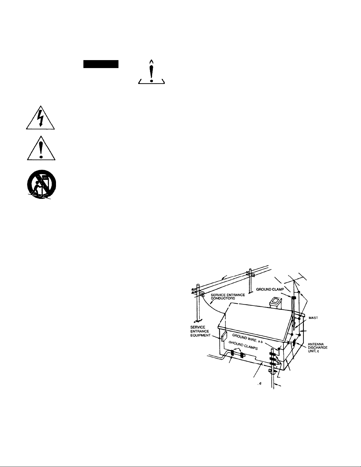
OUTDOOR ANTENNA GROUNDING
If an outside antenna is connected to your tuner or tuner-preamplifier, be
sure the antenna system is grounded so as to provide some protection
against voltage surges and built-up static charges. Section 810 of the
National Electrical Code, ANSI/NFPA No. 70-1984, provides information with
respect to proper grounding of the mast and supporting structure, grounding
of the lead-in wire to an antenna discharge unit, size of grounding
conductors, location of antenna discharge unit, connection to grounding
electrodes, and requirements for the grounding electrode.
a. Use No.10 AWQ (5.3 mm') copper, No.8 AWG (8.4 mm') aluminum,
No.17 AWG (1.0 mm') copper-clad steel or bronze wire, or larger, as a
ground wire.
Secure antenna lead-in and ground wires to house with stand-off
insulators spaced from 4-6 feet (1.22-1.83 m) apart.
c. Mount antenna discharge unit as close as possible to where lead-in
enters house.
d. Use jumper wire not smaller than No.6 AWG (13.3 mm') copjoer, or the
equivalent, when a separate antenna-grounding electrode is used. See NEC
Section 810-21 (j).
EXAMPLE OF ANTENNA GROUNDING AS PER NATIONAL ELECTRICAL CODE INSTRUCTIONS
CONTAINED IN ARTICLE 810 - RADIO AND TELEVISION EQUIPMENT.
The unit should be installed so that its location or position does not interfere
with its proper ventilation. For example, if should not be situated on a bed,
sofa, rug, or similar surface that may block the ventilation openings; or
placed in a built-in installation, such as bookcase or cabinet, that may
impede the flow of air through its ventilation openings.
The unit should be situated away from heal sources such as radiators, heal
registers, stoves, or other devices (including amplifiers) that produce heat.
The unit should be connected to a power-supply outlet only of the voltage
and frequency marked on its rear panel.
The power-supply cord should be routed so that it is not likely to be walked
on or pinched, especially near the plug, convenience receptacles, or where
the cord exits from the unit.
Clean unit only as recommended in its instruction manual.
The power-supply cord of the unit should be unplugged from the wall outlet
when it is to be unused for a long period of time.
Care should be taken so that objects do not fall, and liquids are not spilled,
into the enclosure through any openings.
This unit should be serviced by qualified service personnel when:
A. The power cord or the plug has been damaged; or
B. Objects have fallen, or liquid has been spilled, into the unit; or
C. The unit has been exposed to rain, or liquids of any kind; or
D. The unit does not appear to operate normally, or exhibits a
marked change in performance; or
E. The device has been dropped, or the enclosure damaged.
DO NOT ATTEMPT SERVICING OF THIS UNIT YOURSELF.
REFER SERVICING TO QUALIFIED SERVICE PERSONNEL.
POWER LINES
STANDOFF
INSULATORS, b
ANTENNA
LEAD-IN WIRE
TO EXTERNAL ANTENNA
POWER SERVICE GROUNDING
ELECTRODE SYSTEM
{e. g. interior metal water pipe)
BONDING JUMPER
OPTIONAL ANTENNA GROUNDING
ELECTRODE DRIVEN 8 FEET (2.44 M) INTO
THE EARTH IF REQUIRED BY LOCAL
COOES. SEE NEC SECTION 810-21 (1)
TERMINALS OF RADIO RECEIVER
GROUND WIRE, a.b
GROUND CLAMPS
NOTE TO CATV SYSTEM INSTALLER
This reminder is provided to call the CATV system installer's attention to
Article 820-22 of the National Electrical Code that provides guidelines for
proper grounding and, in particular, specifies that the cable ground shall be
connected to the grounding system of the building, as close to the point of
cable entry as practical.
Page 3

INTRODUCTION
Congratulations on your decision to purchase the ADCOM GTP-600 Surround Sound Tuner/Preamplifier. You’ve made
a wise choice.
The GTP-600 is ADCOM’s first tuner/preamplifier specifically designed for both audiophiles and videophiles who want
the finest in home theater flexibility. The tuner section uses superbly accurate quartz synthesizer technology for excellent
FM and AM reception. The preamplifier section derives extensive sonic benefits from ADCOM's exclusive Class A
biased linear amplifiers and precision Roederstein 1% metal film resistors in all critical circuit paths.
The GTP-600 combines advanced Dolby Pro Logic decoding, ADCOM’s proprietary Cinema enhancement circuit,
Digital Signal Processing (DSP) capability, video switching of both standard (composite) and high definition S-video
signals, on-screen display and learning remote.
A NOTE ON YOUR OWNER’S MANUAL
In a hurry? The QUICK START section will soon have you up and running. However, we strongly recommend that you
refer to the expanded instructions in EVERYTHING YOU NEED TO KNOW to "fine tune" your system for enhanced
enjoyment once everything is working.
If you’re more patient or want more background, start with EVERYTHING YOU NEED TO KNOW. You’ll be rewarded
with a much better understanding of how the GTP-600 works and what its capabilities are.
This unit is manufactured under license from Dolby Laboratories
Licensing Corporation. It is additionally licensed under one or more
of the following patents: U.S. number 3,959,950, Canadian numbers
1,004,603 and 1,037,877. "Dolby,” "Pro Logic” and the dOUble-D
symbol are trademarks of Dolby Laboratories Licensing Corporation.
Page 4
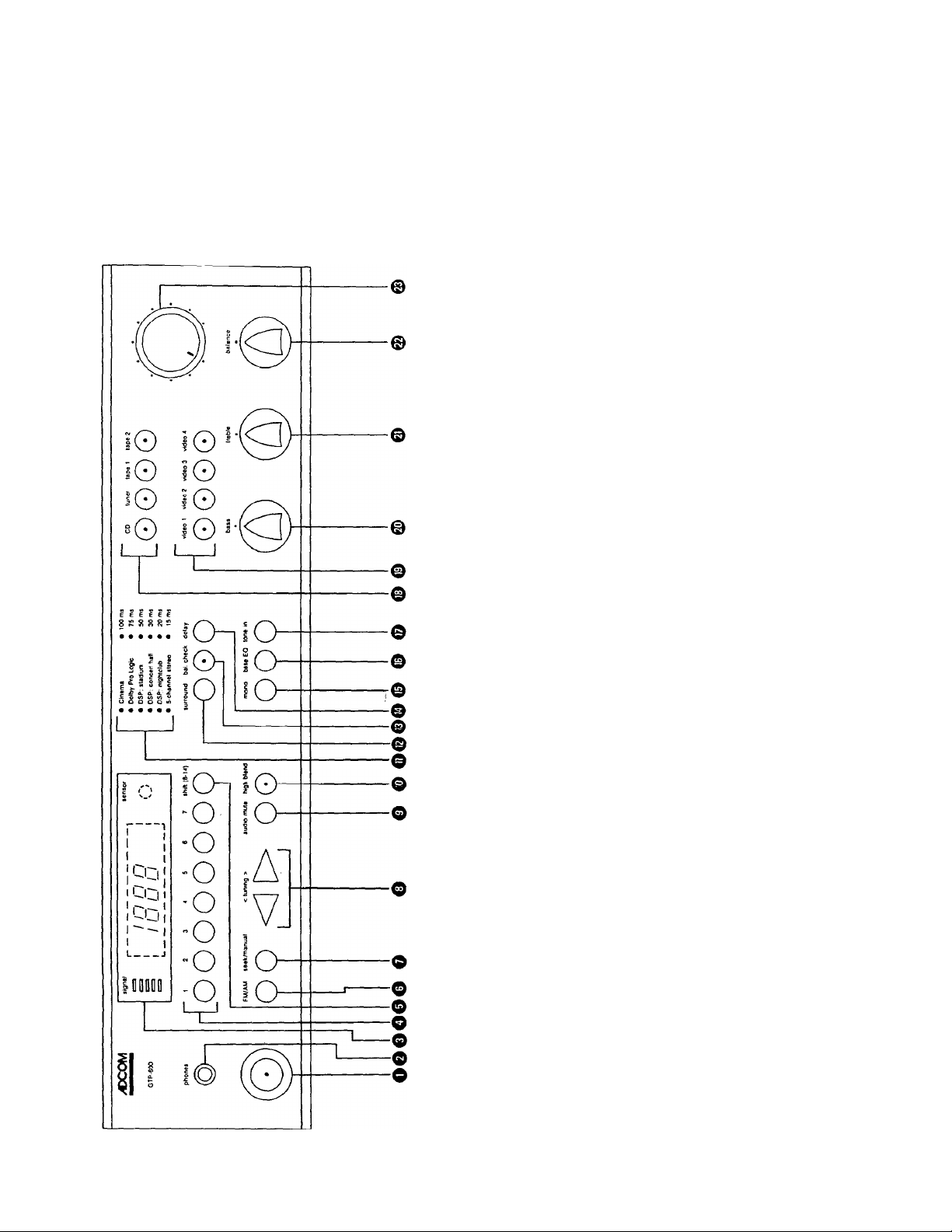
FRONT and REAR PANELS
We carefully designed the GTP-600 with your enjoyment in mind. We’ve arranged the controls in functional groups so
that their use is almost intuitive. The rear panel also benefits from the same design goals. Take a few moments to
familiarize yourself with them. You’ll find references to the circled ID numbers throughout the rest of this manual.
GTP-600 FRONT PANEL DIAGRAM
C/2
o O
O O
_Q)
(D O
CO (n
CD CD _
poo
8 8
CO iO
o O
^ O ^ CO D
3 O CD E CO O
< > m CD >
o
o ar
o o
CD
CO
CD
P
E ^
2 g
rj CO <D O CO n
CO CD Q 2 CD
— O
c
o
^ 8 CD
0^ c E
c
o
t5 o CO 5
0) S § O “
o V) CO |jj
£=
o
o
o
o
t5
(D
CO ^
^ T5
c 9
CO C
F CD
c
‘c
CD
3
0)
CO
o oo©o
-C
0
1
CO
^ s
c CO
iO O
to '-D
^ c
0) —
$ Q
O LLI
__
I
0
®o©o
CO
c
0
3
X) a=
C o
1 s
TO QJ
Q- 3
E
8^.0
F <
O 5
CO o
o 5
Cl
m ^
<0 ^
x>
Q. P P S
CO
CO C C >
CD
X Q
^ Q
— >.
o _cg
D CD
2 Q
^ ‘O
c O
llD) 3
S 2
2 3
u_ CO
c
o
CO
3
c
XI
o
3
X
n
CO
o
p
CO
CO
0)
p
CL-
CO
W
o
ro
p
T3
c
O
P
P
CO
Page 5
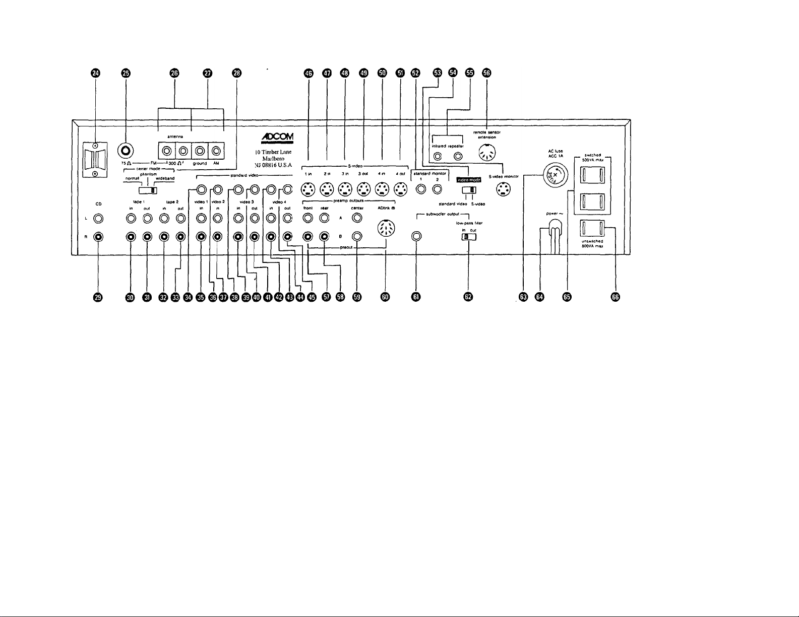
© AM loop antenna holder
©
75 ohm (coax) FM
antenna connection
© 300 ohm (twinlead) FM
antenna connections
© AM antenna connections
© Center channel mode
switch
© CD inputs (L & R)
Tape 1 inputs (L & R)
©
Tape 1 outputs (L & R)
0
© Tape 2 inputs (L & R)
© Tape 2 outputs (L & R)
©
Video 1 input (standard
video)
Video 1 inputs (L & R
©
audio)
© Video 2 input (standard
video) audio)
© Video 2 inputs (L & R
audio)
© Video 3 input (standard
video)
© Video 3 inputs (L & R
audio)
© Video 3 output (standard
video)
© Video 3 outputs (L & R
audio)
© Video 4 input (standard
video)
© Video 4 inputs (L & R
audio)
© Video 4 output (standard
video)
©
Video 4 outputs (L & R
©
Video 1 input (S-video)
©
Video 2 input (S-video)
©
Video 3 input (S-video)
©
Video 3 output (S-video)
©
Video 4 input (S-video)
Video 4 output (S-video)
0
Standard monitor (TV)
0
outputs (x 2)
©
Video mode (Standard or
S-video) switch
©
S-video monitor (TV)
output
©
Remote control infrared
repeater outputs (x 2)
©
Remote control sensor
extension
0
Main preamp outputs
(Front Left & Front Right)
0 Main preamp outputs
(Rear Left & Rear Right)
© Main preamp outputs
(Center channel x 2)
(J) Main preamp output
(ADlink - multichannel DIN
connector)
0 Main preamp output
(Subwoofer)
® Subwoofer low pass filter
selector switch
® AC line fuse receptacle
a\C line cord
© Switched AC outlets (x 2)
— certain models only
© Unswitched AC outlet —
certain models only
Q
H
TD
I
O)
o
o
30
m
>
30
3>
z
m
r”
g
>
o
33
>
Page 6
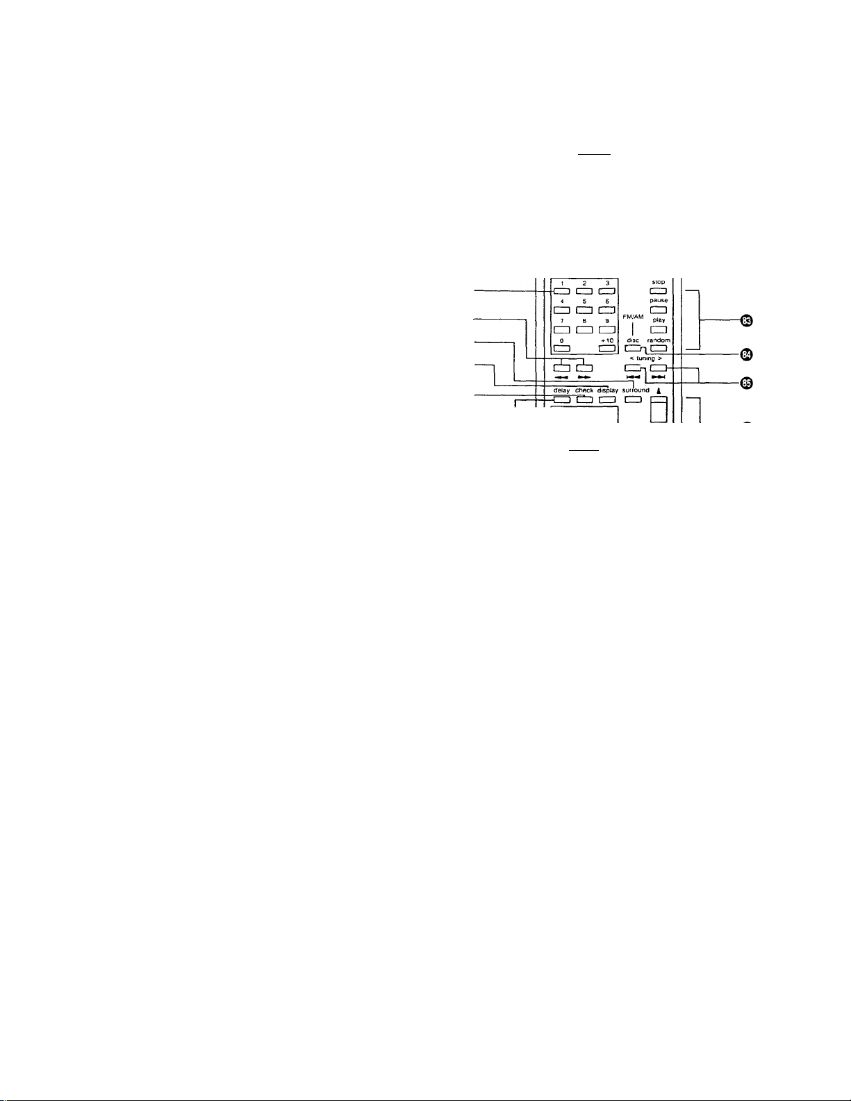
GTP-600 REMOTE CONTROL DIAGRAM
© Learn indicator LED
© Learn/Use mode switch
© Power On/Off
® Input selectors
o Numeric keypad
© Forward/Reverse scan (CD)
0 Surround mode selector
© Display (On Screen Display) On/Off
© Check (Balance Check) On/Off
© Delay selector
0
Rear level set Up/Down
0
Center level set Up/Down
© Sub(woofer) level set Up/Down
© Transmit LED
0 Reset button
© Audio mute On/Off
© CD player controls
© FM/AM select & CD disc select
© FM/AM tuning Up/Down & CD track
change buttons
© Master volume Up/Down
®-
©©-
®-
• learn 1 { r ~| transmit -
CD tuner tape 1 tape 2
(ZD CD cm CD
v>Oeo A video 2 video 3 video t
(ZD (ZD CD CD
111
(ZD CD CD
rear center sub
CD CD (ZD
T T T
ADCOM
mule
CD-
-©
Q
-©
© © ©
QUICK START
OUT OF THE BOX---
1) UNPACKING: Unpack the GTP-600 carefully, MAKE SURE YOU REMOVE THE REMOTE CONTROL FROM THE
BOX. Put the foam inserts and other packing materials back in the carton and save it.
2) PLACEMENT: Select a stable, vibration-free location for the GTP-600 as close as possible to your other audio
and video components.
3) POWER OFF!: Turn off all the other components in your system. This means everything. And don’t plug the GTP-
600 into the AC outlet yet.
CONNECTIONS
4) FM ANTENNA: Depending on the antenna you use, connect it to either the 75 Ohm terminal © or the 300-Ohm
screw terminals © on the GTP-600's rear panel.
The “T" shaped FM antenna supplied with the GTP-600 is a 300 ohm "dipole” and should be connected
accordingly. You’ll find it adequate for most installations.
5) AM ANTENNA: Connect an AM antenna to the ’’Ground’’ and “AM” screw terminals ©on the GTP-600’s rear
panel.
The supplied AM loop antenna is sufficient for all but the most difficult reception areas. However, it must be
oriented for best reception.
Page 7

6) AUDIO SOURCE HOOK UP: Connect up to three external high level audio sources (CD players, cassette decks,
MD or DCC devices, etc.) to the appropriate input jacks (© © and ©) on the rear panel. Be sure to observe
proper channel continuity (Left channel to Left channel, Right to Right.)
The line inputs on all audio recording devices should be connected to the GTP-600's corresponding tape output
jacks (0or ©).
7) VIDEO SOURCE HOOK UP: Make all video connections to and from the GTP-600 (including TV monitor) using
EITHER the standard (composite) video jacks OR the high definition S-video connectors. DO NOT INTERMIX.
Connect up to four video sources (videodisc players, video cassette players, camcorders, video cassette recorders,
etc.) to the appropriate jacks on the rear panel.
Video 1 and 2 inputs are for play-only devices (videodisc players for example) v\/hile Video 3 and Video 4 have
complete input and output connections for a play/record device such as a VCR.
Standard (composite) video connections go to the appropriate yellow color-keyed RCA jacks (© © © ©
© and ©).
High definition S-video connections go to the appropriate multi-pin connectors (© through ©).
Left and Right channel audio connections for your video components go to the appropriate white and red
color-keyed RCA jacks (© © © © © and © ).
8) TV HOOK UP: Connect your TV monitor or receiver to either of the two Standard (composite) Monitor outputs
© or the S-video Monitor output © by using the appropriate cable from the GTP-600 to the corresponding input
on the TV. Use the same format (standard or S-video) already chosen for other video components.
If you own an older TV with only an antenna input (either screw terminals or an “F" type connector) you will need
to purchase an RF modulator at an electronic parts store. Check your TV’s Owner’s Manual for additional information.
9) VIDEO MODE SELECTION: Set the Video Mode switch ©to either Standard (composite) or S-video, depending
on which format you have chosen for video signal transfer,
10) CENTER CHANNEL MODE SELECTION: Adjust the Center Mode switch © to the appropriate position.
’’Normal" restricts bass information below 100 Hz. It is used when a center channel speaker has somewhat
limited bass capability.
Choose '"Wideband” when the center channel speaker/amplifier combination is capable of extended bass response.
Choose "Phantom” only when a center channel speaker is not being used.
11) PREAMP TO POWER AMP CONNECTIONS: Connect the GTP-600 S 5 Main Preamplifier Outputs (® - ©)
to the corresponding power amplifier inputs. Remember to maintain proper channel continuity: Connect the GTP600’s right front output to the power amplifier’s right front input, etc.
The multi-pin ADIink'"" connector © simplifies these connections when used with ADCOM 5 or 6 channel power
amplifiers.
12) SUBWOOFER CONNECTIONS: Connect á powered (self-amplified) subwoofer to the Subwoofer output ©
using an RCA to RCA patchcord to the line-level (or amplifier) input of the subwoofer. Adjust the Low-pass Filter
switch © in accordance with the instructions supplied with the subwoofer.
A non-amplified subwoofer used with a separate power amplifier should be connected in the same manner:
Subwoofer output ©to amplifier input. Connect the subwoofer to the amplifier according to the instructions
supplied with those units.
13) REMOTE EXTENSION ACCESSORIES; Connect up to two (optional) remote control repeater units (IRA-500) to
the Infrared Repeater outputs © if needed.
Connect the (optional) remote control sensor (XR-500 II or SPM-500 II) to the Remote Sensor Extension ©
according to the instructions supplied with these units.
£
Page 8

14) AC CONVENIENCE OUTLETS (Certain models only);
A) Switched outlets: Plug up to two sources (CD player, etc.) into the switched AC outlets ©. These components
will receive AC whenever the GTP-600 is "ON” (provided, of course, that the GTP-600 itself is plugged into a
live AC outlet.)
B) Unswitched outlet: This outlet © supplies AC whenever the GTP-600 is plugged into a live AC outlet
regardless of whether the GTP-600 is “ON" or not. The unswitched outlet is usually reserved for mechanical
devices (such as a tape deck) that might Pe damaged if power was inadvertently cut off before the mechanism
disengages.
15) AC LINE FUSE; This socket © holds the AC line fuse. In the unlikely event that the AC fuse opens, replace it
ONLY with a fuse of the exact type and rating. A subsequent fuse failure means that your GTP-600 needs service.
16) AC LINE CORD: Plug the AC cord © into an unswitched AC wall outlet so that power to the GTP-600 can’t be
accidentally interrupted by turning off an AC switch.
BASIC OPERATION
NOTE: This section assumes that you’ve set up the rest of your system (sources, power amplifiers and speakers, etc.) in
accordance with the instructions supplied with these units.
17) VOLUME DOWN — POWER ON!: Turn the GTP-600’s volume control © all the way down (fully counterclockwise.)
Turn the unit on by pressing the power switch O- Then turn the other system components on: sources first, then
power amplifiers.
18) SOURCE SELECTION and RECORDING: Choose a source by pressing the GTP-600's appropriate Audio or
Video source selectors (© & respectively). Then operate the source component according to the supplied
instructions.
NOTE: Signals from the chosen source are available at all recording outputs. This means, for example, that you
can record a CD on a Hi Fi VCR without changing any of the rear panel connections. Conversely, you can record
the audio portion of a video tape on an audio cassette recorder. ■
19) THE TUNER: The Tuner button selects the internal AM/FM/FM Stereo tuner. Choose FM or AM by using the FM/
AM selector button ©., Tune in the desired station.
20) TONE CONTROLS: The Bass and Treble controls (®& ©respectively) emphasize or decrease low and high
frequencies to suit your taste. These controls are active only when the Tone in switch O is depressed.
A separate Bass EQ switch ©adds a predetermined amount of bass energy to all signals. You may find this
particularly convenient to enhance video soundtracks. This circuit operates independently of the Tone in switch.
21) BALANCE CONTROL: The Balance control ©allows you to compensate for source eccentricities or unusual
listening room acoustics by adjusting relative output from the main system speakers. If you want more output
from the right speaker, for example, turn the control to the right.
22) VOLUME CONTROL: The Volume control © is the master gain control for the entire system. Turn it clockwise
to increase volume and counterclockwise to decrease volume.
NOTE: The LED on the front panel Volume control glows steadily when in normal operation. When the Audio
mute switch ©is engaged, the LED blinks.
23) AUDIO MUTE CONTROL ©; Push this to fully mute the output. The Volume control LED blinks when mute is
engaged.
24) MONO SWITCH ©; Push this for a mono signal. You’ll also find this useful to reduce background noise on very
weak FM broadcasts.
25) THE REMOTE CONTROL: The RC-65 hand held remote controller duplicates all front panel controls. It also
contains additional controls that are used only from remote locations. Basic operating instructions are on the rear
of the RC-65.
The RC-65 is a “learning” remote and can be programmed to operate many other components.
Page 9

ADVANCED OPERATION
26) SYSTEM BALANCING: After you’ve physically set up your system, use the RC-65 remote controller to balance
the relative outputs of all speakers to fully enjoy the spatial benefits of Dolby Pro Logic decoding.
A) Verify that you’re in Cinema or Dolby Pro Logic mode by making sure that the appropriate LEDs (the ones to
the left of “Cinema” and “Dolby Pro Logic”) are lighted. If some other mode is indicated, press the “Surround”
button (front panel ©or remote ©) until the proper LEDs appear.
B) Activate the Balance Check circuit by pressing the “bal check” button (front panel ©or remote ©). A test
tone that sounds like rushing water will start in the left front loudspeaker.
C) Adjust the center and rear channel outputs so that the sequential “rushing water” noise is equally loud when
heard through each speaker. Sit in your favorite chair and use the remote control for this adjustment.
D) Turn off the sequential test tone by pushing the “bal check” control (©or ©) again.
27) SURROUND and DELAY CHOICES: The GTP-600 gives you 7 operating modes to choose from. Choose the
mode best suited for your source by pushing the front panel or remote Surround button(©& © respectively) until
the LED beside the chosen mode lights. If no LED is visible, you have chosen 2 channel stereo (or surround
bypass.)
Each surround mode has a pre-programmed delay setting chosen to best complement that mode. You may
select another by sequentially pushing the delay button (© & ©). Note that not all delay settings are available
with all surround choices.
28) ON-SCREEN DISPLAY: The on-screen display gives an instant status check of selected inputs, operating modes,
delay choices, etc. Press the remote control’s Display button © to turn on the display, Press it again to turn it off.
EVERYTHING YOU NEED TO KNOW
This section uses the same paragraph numbers as the preceding QUICK START section,
additional information useful and enjoyable.
OUTOFTHEBOX--
1 ) UNPACKING: As part of ADCOM’s quality control procedures, your GTP-600 was carefully inspected for physical
imperfections and electrical performance before it left our plant. In the event of physical damage, notify your
ADCOM dealer immediately and request help in filing a written damage claim.
THE RIGHT TO A CLAIM AGAINST A COMMON CARRIER CAN BE FORFEITED IF THE CARRIER IS NOT NOTIFIED
PROMPTLY IN WRITING AND IF THE SHIPPING CARTON AND PACKING MATERIALS ARE NOT AVAILABLE
FOR INSPECTION. SAVE ALL PACKING MATERIALS UNTIL THE CLAIM HAS BEEN SETTLED.
The foam packing and carton were specifically designed to protect your GTP-600. Even though space is often at
a premium in today’s homes, we recommend that you save the packing materials in case you need to ship the unit
anywhere in the future.
2) PLACEMENT; A stable supporting surface is necessary. The more massive and firmly anchored the supporting
surface is, the less likely you’ll be to experience any problems.
3) POWER OFF!: Turn off system components before initial installation and connection. Remember to give any
power amplifiers sufficient time to fully discharge their power supplies before you begin your connections: 30
seconds after turn-off is usually sufficient.
CONNECTIONS
We hope you find the
4) FM ANTENNA: The “T” shaped 300 ohm dipole antenna supplied with the GTP-600 will probably be adequate for
most installations. After you’ve connected the rest of your system and turned it on, select Tuner from the Audio
Source selectors ©. Then choose FM by pressing the FM/AM selector Q until "FM” appears in the display
Page 10

window. Tune to an FM station. Extend the top of the “T” antenna and rotate it to the position that results in the
best reception. Once you’ve determined that, fasten the antenna to the wall, a cabinet back or even the ceiling so
that the 'T” is aligned as closely as possible to the direction that gave you the best reception.
Remember that the dipole antenna is directional — it is most sensitive to signals arriving at right angles to the
extended “T” and relatively insensitive to signals arriving from the ends of the "T.”
The dipole antenna rapidly looses its effectiveness when rolled up or carelessly dropped behind a cabinet, etc. If
the “T” antenna is undesirable from a functional or decor point of view, your ADCOM dealer will be pleased to
show you a variety of indoor antennas that might be more appropriate. We do suggest, however, that you ask for
a home trial as reception conditions vary enormously from location to location.
The GTP-600 can also be used with a 75 ohm antenna. These are usually large roof mounted antennas and can
provide superior reception when compared to the 300 ohm “dipole.” In addition, most cable companies use 75
ohm cable to distribute FM signals. Connect the GTP-600 to a 75 ohm antenna system by terminating the
connecting cable with an “F” connector (available at most electronic parts stores) and attaching it to the rear
panel 75 ohm antenna terminal ©.
The grounding schemes used by cable companies are very complex and occasionally cause hum when the
cable is attached to the 75 ohm antenna input. An isolation transformer (again, available at most electronic parts
stores) will usually solve the problem.
5) AM ANTENNA; The supplied movable ferrite "loop” will provide reasonable AM reception in most locations. The
loop should be rotated away from the body of the GTP-600 and some experimentation will undoubtedly improve
AM reception.
In the event that you need better reception, you can make your own AM antenna from a single length of insulated
wire. Connect one end of the wire to the terminal marked “AM" and run the other end to a high location in your
home or hang it from a window.
In most cases, a second wire run from the “Ground" terminal to a solid earth ground (a cold water pipe for
example) will also improve AM reception as well as provide a safe “path to ground” in the event that lightning
strikes an outdoor AM antenna.
6) AUDIO SOURCE HOOK UP; Patience and common sense will help you avoid almost all the errors you might
make when rushing the initial installation. Remember to connect Left Channel to Left Channel and Right Channel
to Right Channel, etc. The jacks on all ADCOM products follow conventional color coding; White for Left Channel
and red for Right Channel. Most interconnect cables observe this general guideline: the connectors on each end
of the cable are usually color coded.
We've received many questions about the sonic attributes of premium interconnect cables. We do suggest
that you make sure any cable you use is a “low capacitance” design. (Most are.) Your ADCOM salesperson
will be happy to make cost-effective recommendations based on individual component characteristics and
system complexity.
Page 11

7) VIDEO SOURCE HOOK UP: All of the comments immediately above apply here also, especially the references
to patience and common sense.
You’ll notice that the standard composite video connections use RCA jacks color coded with yellow inserts. This
makes hookup easier by distinguishing the video signal patti from associated audio signals which also use RCA
style jacks.
The S-video connections require a multi-conductor cable with a 5 pin DIN connector at each end. S-video's
higher definition is due in part to separate transmission and processing of the luminance (black and white) and
chrominance (color) video signal components and combining them only when needed. S-video’s “white clip” and
“dark clip" levels are also different.
ADCOM makes no format recommendations. Standard (composite) video is a surprisingly vivid medium when
properly implemented and is far more common. S-video is not as widely available but does have better resolution
capability, particularly when S-video equipped videodisc players are used as sources.
8) TV HOOK UP: The TV monitor/receiver should be connected to either the GTP-600's standard (composite) video
or S-video monitor output and operated in accordance with the instructions furnished with the TV.
Generally speaking, connect the GTP-600's Monitor output to the TV’s VIDEO input (either an RCA jack or an Svideo DIN socket.) DO NOT USE the antenna input. If your TV has more than one video input, choose. (Read the
TV’s instruction manual first.)
Remember to keep the TV switched to the appropriate video input or you won't benefit from the GTP-600’s video
switching or on-screen display capabilities.
NOTE; With the proliferation of cable boxes, VCRs, videodisc players, satellite receivers, etc., there aré many
different system configurations. Unfortunately, it is impossible to cover all of them in this manual. Your
ADCOM dealer will be pleased to map out the correct connection scheme for your component combination.
9) VIDEO MODE SELECTION: The GTP-600 will not support both composite video and S-video formats
simultaneously. Choose one or the other and set the rear panel Video Mode switch © accordingly!
10) CENTER CHANNEL MODE SELECTION: The Center Mode switch © controls the output to the two center
channel preamp outputs ©.
A) The "Normal" (left) position filters bass frequencies below 100 Hz at a rate of 18 dB/octave. Use this position
when you've chosen a smaller center channel speaker that might not be capable of extended bass reproduction.
, Under these circumstances, “Normal" reduces speaker distortion and improves center channel clarity.
This position should also be used when the center channel amplifier is of lower power than the amplifiers
used for left and right front speakers.
B) The “Wideband" position sends a full range signal to the center channel amplifier and speaker. Use this
position when the center channel speaker is acoustically similar to your main left and right speakers and the
center channel speaker/amplifier combination is capable of extended bass reproduction.
C) Use the “Phantom” position when you're not using a center channel speaker. This position splits the Pro
Logic decoder's center channel output between both main speakers to synthesize a center channel image.
Although the “Phantom" position provides an excellent interim step in creating a home theater system, it is
somewhat less effective than using a center channel speaker.
NOTE; The center channel speaker is an essential component in a Dolby Pro Logic equipped home theater
system. It should be placed as close to your TV screen as is physically possible and must be magnetically
shielded to prevent image distortion and possible damage to your picture tube. In conjunction with Dolby Pro
Logic's "adaptive matrix” decoding, the center channel speaker improves coherency by anchoring the soundfield
to the screen's image. Dialog, for example, always appears to be coming from your TV regardless of where you're
sitting in the room. We strongly recommend a center channel speaker. Your ADCOM dealer will be pleased to
show you suitable choioes.
11) PREAMP TO POWER AMP CONNECTIONS: This is, once again, a matter of patience and common sense.
Remember, the only real difference between hooking up a two channel stereo music system and a five or six
channel home theater system is three or four more channels! Take care to observe channel continuity — the GTP600's right front output should go to the power amplifier's right front input, etc.
Page 12

The ADCOM ADIink'"’ connector duplicates all the separate RCA type preamplifier outputs in one 8 pin DlN-style
connector. Use this connector in place of the RCA outputs only with an ADIink'"" equipped ADCOM multi-channel
power amplifier. The ADIink"^ interconnect cable automatically assures proper channel continuity from preamp to
power amp and reduces the number of interconnect cables needed.
12) SUBWOOFER CONNECTIONS: The Subwoofer jack 0 supplies a line level output for direct connection to the
line input of a powered (self-amplified) subwoofer or the input of a dedicated subwoofer power amplifier. The
Subwoofer output is a mono (L-i-R) output — right and left front information is combined or mixed before it is sent
to the jack.
The Low pass filter switch 0 changes the characteristics of the subwoofer output. The “In” position filters high
frequencies above 100 Hz at a rate of 18 dB/octave. This is called a “low pass" filter in tfiat only low frequency
information is allowed to “pass" through. The “Out" position bypasses the filter to send a full range mono signal
from the subwoofer jack.
It is not good audio practice to send a signal through a series of low pass filters and most self-powered subwoofers
have an adjustable low pass filter at their input. For that reason, we suggest that you use either the GTP-600's
filter OR the subwoofer’s filter but NOT BOTH. Read the subwoofer’s instruction manual for further information.
After that, you may want to experiment to determine the best sounding alternative.
13) REMOTE EXTENSION ACCESSORIES:
ADCOM's remote control accessories can add enormous flexibility when used with the GTP-600.
Optional remote sensors (either the component-styled XR-50011 or the in-wall SPM-500 II) allow you to fully control
the GTP-600 from a number of additional locations in your home. Either sensor plugs into the Remote Sensor
Extension 0 Complete instructions are included with the XR-500 II and SPM-500 II.
The IRA-500 (also optional) repeats infrared command pulses received from XR-500 II or SPM-500 II external
sensors. It should be plugged into either of the Infrared Repeater outputs ©. The triangular end of the IRA-500
should be placed close to the sensor of the non-ADCOM component and then secured with the supplied double
sided mounting tape.
The IRA-500 also resolves the dilemma inherent in setting up a technically complete but non-intrusive home
entertainment system. All of the components can be hidden in custom cabinets or closets. Aside from a TV
screen, the only item that needs to be visible is an XR-500 II or SPM-500 II external sensor.
We’ll be happy to send you additional information on these units
simply call ADCOM’s Customer Service
Department (see the rear of this manual.)
14) AC CONVENIENCE OUTLETS (Certain models only):
A) Switched outlets; Make sure that the components plugged into these outlets do not draw in excess of 500
watts. You’ll find the power consumption of most components marked on the rear panel near the power cord
or model number identification.
B) Unswitched outlet: Do not exceed 800 watts. Remember that large power amplifiers can impose substantial
demands on any electrical outlet, especially during “turn on.”
For your information, the proper unit of measure here is the Volt/Amp, abbreviated VA. A Volt/Amp is the AC
equivalent of a watt. However, most people use the term “watt,” so we won’t confuse the issue.
We strongly recommend the use of ADCOM’s ACE-515 AC line enhancer/sequential switcher. In addition to
providing the convenience and safety of surge protected multiple outlets and dramatically superior RF and
EMI filtering, the ACE-515 simplifies system turn-on and turn-off as well. Time delay switching protects your
speakers from the potentially annoying effects of power transients. Check with your ADCOM dealer for
details.
15) AC LINE FUSE: The line fuse is a 1 ampere AGO type. It should be replaced only with a fuse of the same type
and rating. A higher rating or different fuse type will not protect the GTP-600, will void the warranty, and may be
a fire hazard!
This fuse DOES NOT PROTECT the AC convenience outlets.
10
Page 13

16) AC LINE CORD: This should be plugged into an unswitched outlet providing the appropriate voltage at either 50
or 60 Hz. If the unit is without AC power for an extended period of time, usually longer than 48 hours, station
memory and remote turn-on features may be affected.
BASIC OPERATION
17) VOLUME DOWN — POWER ON!: Avoid unintentional initial high sound levels by turning the volume control
down (fully counterclockwise) before powering the system.
18) SOURCE SELECTION and RECORDING : The GTP-600 provides extensive recording and “cross dubbing”
capability. Any selected source is available at all audio and video recording outputs. The only exception to this
rule occurs when you are transferring from one recording device to another; The GTP-600 automatically blocks,
for example, the output from Tape 1 from appearing at the inputs of the same device. This prevents any inadvertent
and possibly destructive feedback loops from developing.
19) THE TUNER: The Tuner section is responsible for processing and amplifying extremely weak signals “pulled in”
by the appropriate antenna. ADCOM’s refined quartz synthesis technology makes this a highly accurate exercise.
However, Using the tuner is a simple process.
A) The Display window O provides an instant status check of the following important items:
1) AM & FM signal strength; Up to five red LEDs on the left hand side of the display will light depending on
signal strength. This display can help you find the best location for your antenna — the more LEDs
showing, the stronger the signal.
2) FM/AM band/frequency indicator: This is displayed at the center of the window.
3) FM “Seek" mode indicator; Appears immediately above the “MHz” indicator. Note that Seek does not
function in AM. (See Section B2 below.)
4) Preset indicator; Located on the far right hand side of the display, this lights when one of the pre
programmed stations is chosen,
B) After selecting FM or AM (©or ©), tune to the desired station by one of the following methods:
1) Press one of the Tuning up/down arrows O until the Display © shows the proper station frequency.
2) Enter “Seek” mode (FM only) by pressing the Seek/manual button ©. “Seek" appears in the display.
Then press either of the Tuning up/down arrows ©. The GTP-600 will automatically advance to the next
active broadcast frequency. Note: “Seek” is not operative in AM mode.
3) Press any of the Tuner Preset buttons © to recall preprogrammed station frequencies. Of course, this
works only after you’ve programmed your favorite stations. Here's how;
a) Tune to ll ie desired broadcast frequency by using either of the methods outlined in B1 or B2 above.
b) Decide what preset # you want to assign to that frequency.
c) Hold down the corresponding button until the word “preset" and that number appears on the right
hand side of the display.
Note that preset positions 1 through 7 are accessed directly — simply push the button with the
corresponding number.
To access presets 8 through 14, press the Shift button © and then a preset button. For example, if
you want preset number 11, press Shift and then press Preset 4 (7+4=11). If you want preset
number 8, press Shift and Preset 1 in that order (7+1 =8).
Note that the +10 button on the remote is the equivalent of the shift button on the front panel.
All preset numbers are “random” in that you can assign any preset number to any FM or AM signal.
In other words, preset 1 can be AM, presets 2-4 can be FM, preset 5 can be AM, etc.
C) The High blend button © can reduce the background noise sometimes encountered on weaker stereo FM
signals. The “In” position also turns off the FM mute circuit and may make it possible to receive very weak
signals that would otherwise be ignored by the tuner’s circuitry.
11
Page 14

20) TONE CONTROLS: ADCOM's tone controls (®& ©) are far more subtle than similar controls on competitive
units. While conventional controls affect large portions of the midrange in addition to either bass or treble, ADCOM’s
circuits affect only the frequency extremes and leave the critical midrange virtually untouched.
The benefit is that musical clarity is unchanged even when you select large amounts of tonal compensation. For
video applications, this design has the advantage of not decreasing dialog intelligibility.
For absolute sonic purity, these circuits are bypassed until the Tone in button o is pressed.
21) BALANCE CONTROL: The balance control © adjusts for unequal volume levels between the front left and front
right channels.
To use it accurately, select the Bypass operating mode (no surround mode LEDs lighted.) Use a mono source (or
press the Mono switch © to the "In” position) and adjust the balance control until the sound appears to originate
from a point centered between the front left and front right speakers. The final position of the balance knob will
vary depending on room acoustics and your listening/viewing position.
22) VOLUME CONTROL: This knob © controls a precision 6-segment potentiometer that determines loudspeaker
and headphone volume. The control features "stepless" operation for precise gain adjustment.
The LED located on the outer edge of the knob’s front surface glows steadily during normal operation. When
Audio mute Q is engaged, the LED flashes at 0.5 second intervals as a reminder. CAUTION; Do not disengage
Audio mute while the Volume control is set higher than approximately 10:00 O’clock.
23) AUDIO MUTE CONTROL ©; This control fully mutes the GTP-600’s main and headphone outputs. This is in
contrast to most competitive circuits that simply reduce the output by an arbitrary fraction. This conventional
approach is problematic in that our ears perceive loudness in a relative rather than an absolute way. Circuits that
simply reduce gain have a different subjective effect depending on the original position of the volume control:
ADCOM’s infinite attenuation circuit has the same subjective effect at any volume control position.
24) MONO SWITCH ©; This has several uses. As stated before, you can decrease the background noise of weaker
stereo EM signals by pressing this switch. (Actually, you should first use the High blend button. If that doesn’t
screen enough noise out of the signal, try Mono. In addition. Mono is used whenever you need a monaural signal
in Bypass (2 channel stereo) mode to properly phase left and right loudspeakers, etc.
25) THE REMOTE CONTROL: Basic operating instructions for the RC-65 hand held controller are on the back of the
RC-65. Please refer to them as needed.
The RC-65 has three operating modes: Remote Operation, Learn and Delete. Command codes for the GTP-600
and ADCOM CD players are already preprogrammed into the RC-65’s non-volatile memory; These ADCOM-
specific commands CAN NOT be erased.
Flowever, non-ADCOM codes can be programmed into the RC-65 to supersede the ADCOM codes if desired. In
addition, other non-dedicated keys can also be programmed. This allows you to teach the RC-65 commands for
up to eight other components and use it as the remote controller for a complex audio/video home entertainment
system. Of course, the RC-65 can also be “deprogrammed” and then "reprogrammed” with new commands
when you change components.
A) To use the RC-65 as a dedicated remote controller for the GTP-600 and other ADCOM components, follow
these instructions;
1) Select the desired source by pressing the proper Input Selector button ®. The Transmit LED © flashes
to confirm.
2) Select the desired function for that source by pressing the appropriate command key. The transmit LED
flashes.
For example, if you want to turn on the GTP-600, select the CD input and start playing disc 4 in a GCD-600,
press Power ©, press CD ®, press Play ®, press Disc ©, then press “0” and “4” on the numeric keypad
©
B) To program the RC-65 with commands for other components;
1) Place the RC-65 and other remote controller so that the infrared transmitter elements face each other —
usually this is a “top to top” position.
12
Page 15

2) Press the RC-65 Learn key © to enter Learn mode. Th6 Lesrn LED © glows steadily.
3) Press the proper RC-65 Input Selector button to identify the corresponding component. The Learn LED
blinks twice.
4) Press the RC-65 command key you wish to program. The Learn LED blinks once.
5) Press and hold the corresponding key on the other remote until the RC-65 Learn LED blinks twice. The
Learn LED then resumes steady operation.
A prograrnming error is indicated by simultaneous operation of Learn and Transmit LEDs. If this happens,
repeat steps 3 through 5 as needed.
6) Repeat steps 3 through 5 above for all other desired commands.
7) When finished, press the Learn key to exit Learn mode. The Learn LED goes out.
C) To delete previously programmed commands (except non-erasable ADCOM commands):
1) Press the RC-65 Learn key © to enter Learn mode. The Learn LED © glows steadily.
2) Press the proper RC-65 Input Selector button to identify the corresponding component. The Learn LED
blinks twice.
3) Press the RC-65 Reset button ©. The Learn LED blinks continuously.
4) Press the RC-65 command key you wish to clear. The Learn LED stops blinking & resumes steady
operation.
Note: You can delete an entire bank of buttons (all command keys associated with a particular Input
Selector) at once by pressing the appropriate Input Selector again.
5) Repeat steps 3 & 4 as desired.
6) Press the Learn key to exit Learn mode. Learn LED goes out.
ADVANCED OPERATION
26) SYSTEM BALANCING: Accurate balancing enhances the spatial accuracy of your audio/video playback system
by matching the acoustic levels of all system speakers in your room as closely as possible. Once you’ve done
this, any level differences from left to center or from center to rear, etc., are differences intended by the creators of
the original soundtrack, not some unwanted aberration caused by the acoustics of your room.
EVERY ROOM IS ACOUSTICALLY DIFFERENT AND THE RELATIVE CHANNEL-TO-CHANNEL LEVELS WILL
CHANGE AS YOU MOVE AROUND THE ROOM. THIS MEANS THAT YOU SHOULD PERFORM THE BALANCE
CHECK WHILE SEATED IN YOUR FAVORITE LISTENING/VIEWING LOCATION. That’s why we’ve included the
necessary center, rear, and subwoofer level adjustments ONLY on the RC-65 hand held remote controller.
A) Activate the ’’Balance check" circuit: Push the Bal check button © An internal signal generator interrupts
the normal audio information and sends a test tone to all loudspeakers sequentially. The test tone is a filtered
broadband signal close in overall balance to the normal distribution of tones encountered in real life.
The tone generator will “step” through all speakers sequentially beginning with the left front. After two seconds
of left front output, the tone will shift to the center channel.
B) Use the “Center level Up/Down" buttons ©to adjust center channel output to match left channel volume as
closely as possible.
C) After approximately two seconds, the center channel will mute and you’ll hear the test tone through the right
front speaker, probably at the same level as that of the left channel. If this is the case, do nothing.
If there is a substantial difference between left front and right front outputs, correct the difference with the
GTPSOO’s balance control® Significant placement differences for left and right front speakers may cause
this imbalance: Ideally, they should be spaced symmetrically on either side of the TV screen. If room decor
makes this placement difficult, or if you prefer to sit off-center from the TV screen, you may need left-right
balance correction.
13
Page 16

D) The test tone will shift to the rear speakers. Use the “Rear Level Up” and “Rear Level Down” buttons © to
adjust rear channel output to match that of the front left, center, and front right speakers.
You'll probably need to let the Balance Check test tones cycle through all speakers three or four times until you've
matched levels closely. Don't worry about how fast you can accomplish this balance adjustment — just take your
time and do it carefully.
NOTE: DO NOT PLAY ANY OTHER SOURCE THROUGH THE GTP-600 WHEN USING THE BALANCE CHECK
CIRCUIT; if you need to check balances when playing a source, simply put the source on “Pause,” go through the
balance check routine, then resume playing the source.
27) SURROUND and DELAY CHOICES;
The GTP-600 is an enormously flexible unit. This section is the most subjective in the entire Owner’s Manual: Feel
free to take the suggestions here as starting points for your own experimentation. Above all, enjoy!
A) Choosing the proper operating mode:
The GTP-600 provides seven operating modes selected by the “Surround" button on the front panel © or the
remote controller e These are: Cinema, Dolby Pro Logic, Stadium, Concert Hall, Nightclub, 5 channel
stereo, and Bypass (2 channel stereo.) Each of the first six modes is indicated by a front panel LED. (The
Cinema mode displays two LEDs — one to the left of “Cinema" and the second to the left of “Dolby Pro
Logic.”) In Bypass, or 2 channel stereo, no Mode LED lights.
1) CINEMA: This ADCOM circuit enhances the dimensional accuracy of Dolby Pro Logic decoding with
proprietary signal processing techniques to more closely approximate the acoustical soundfield of a
large movie theater.
A shelving filter with a corner frequency of 7 kHz reduces the often excessive high frequencies that make
some video soundtracks fatiguing to listen to. In addition, Cinema mode adds diminishing multiple delays
through the rear speakers to diffuse the surround information even further than is possible through Dolby
Pro Logic.
Left & right front output: enhanced Pro Logic matrix
Center channel; Yes
Initial rear delay setting; 30 milliseconds
Additional delay choice: 20 milliseconds
2) DOLBY PRO LOGIC is one of the two preferred modes for properly processing Dolby Surround”^ encoded
video soundtracks, a growing number of CDs, and even the audio portion of some computer games!; In
this mode, the GTP-600 presents a spatially correct soundstage with precise lateral imaging and front to
back depth.
Left & right front output: Pro Logic matrix
Center channel output; Yes
Initial delay setting; 20 milliseconds
Additional delay choices; 30 & 15 milliseconds
3) STADIUM is used for non-Dolby Surround encoded material and recreates a large and acoustically
reverberant environment well suited for video sporting events and playback of music that is usually
performed in large outdoor arenas. A slight upper midrange frequency emphasis is added to the front
channels to enhance intelligibility. STADIUM mode is also well suited for playback of older epic movies
with mono soundtracks.
Left & right front output: Wide matrix
Center channel output: No
Initial delay setting: 75 milliseconds
Additional delay choices: 100 & 50 milliseconds
14
Page 17

4) CONCERT HALL replicates an indoor performance space that is still relatively large. Front channel
frequency response is fiat for maximum musical clarity while the diminishing multiple rear channel delays
first seen in Cinema mode enhance the sense of spaciousness.
Left & right front output; Stereo
Center channel output: No
Initial delay setting: 50 milliseconds
Additional delay choices: 75 & 30 milliseconds
5) NIGHTCLUB synthesizes a smaller and more intimate soundfield ideal for many types of jazz and popular
music. NIGHTCLUB is also a good choice for playback of classic movies with mono soundtracks.
Left & right front output: Narrow matrix
Center channel output: No
Initial delay setting: 15 milliseconds
Additional delay choices: 30 & 20 milliseconds
6) 5 CHANNEL STEREO sends a mono (L + R) signal to the center channel speaker. When no delay is
chosen (the default choice,) left front information goes to the left rear speaker and right front data to the
right rear speaker. If delay is chosen, the left and right rear outputs are summed to mono and then sent
through the delay line.
Left & right front output: Stereo
Center channel output: Yes (L+R)
Initial delay setting: No delay (stereo rear)
Additional delay choices; 100, 75, 50, 30, 20 & 15 milliseconds (mono rear)
7) 2 CHANNEL STEREO (Bypass); This is the “what’s on the disc is what you get” mode; No processing, no
delay and no center channel. Obviously, this mode is for the serious listener who wants the maximum in
stereo music reproduction. Here, the full audible benefits of ADCOM's proprietary linear gain line amplifier
stages and precision Roederstein 1% metal film resistors are obvious.
Left & right front output; Stereo
Center channel output; No
Initial delay setting; None
Additional delay choices; None
B) Choosing the proper rear channel delay setting
Rear channel delay (available in Cinema, Dolby Pro Logic, Stadium, Concert Hall. Nightclub and 5 channel
stereo operating modes) is a technique that has been used in consumer audio equipment since the early
70s. Sometimes confused with the various quadraphonic technologies briefly popular two decades ago,
time delay is a much more defined and exact process.
Briefly stated, time delay takes information from the rear (or surround) output of the decoder, “stores” it for a
brief period of time (usually less than one tenth of a second), and then sends it to the rear speakers. While a
useful technique to enhance apparent spaciousness and ambience, time delay also serves a specific purpose
in Cinema and Dolby Surround playback. Here, proper time delay prevents us from hearing front channel
information, particularly dialog, from the rear speakers. Based on a psychoacoustic effect called “masking,"
this technique preserves the proper directional clues intended by the source’s producer. For this reason,
both Cinema and Dolby Pro Logic modes intentionally limit rear channel time delay to very small amounts.
If you delay rear channel information for a longer period, you lose the "masking” effect and become aware of
a growing discontinuity between front and rear outputs. Eventually, you’ll perceive the rear channel output as
a discrete echo rather as an integral part of a coherent soundfield. Of course, this is exactly what happens in
a large environment like a stadium. That's why ADCOM has included longer delay times in the GTP-600; the
additional aural flexibility makes reproduction of some audio/video events more realistic.
Somewhere in the middle of this range of effects, time delay has other interesting and useful applications. For
example, longer delay times often give the impression that we are in a large room — the longer the delay, the
larger the apparent space is. If we’re not particularly concerned with the “masking effect,” we can experiment.
15
Page 18

Telephone inquiries are welcomed from Monday through Friday between 9 AM and 4 PM, Eastern Time.
Please call (732)683-2356
We'll also be happy to answer FAX inquiries sent to ((732)683-9792 . Please include your phone and FAX number
so we can respond.
When inquiring about your unit, please include the serial number, the name of the dealer from whom you purchased
the unit and the date or purchase.
If we ask you to return the unit to us for service, we will issue a specific Return Authorization number for your use.
UNDER NO CIRCUMSTANCES SHOULD THE UNIT BE SHIPPED TO US WITHOUT PROPER AUTHORIZATION
OR PACKED IN ANYTHING OTHER THAN ITS ORIGINAL PACKING.
If the original packing has been lost, discarded or damaged, we will be happy to supply a replacement at a
nominal charge. Please mention your need when you call or write.
Always ship PREPAID via UPS (United Parcel Service) or other appropriate carrier. FREIGHT COLLECT SHIPMENTS
WILL BE REFUSED.
DO NOT SHIP VIA PARCEL POST as the packaging may not withstand handling by our Postal Service.
17
Page 19

GTP-600 SPECIFICATIONS
Preamplifier Section
Output Impedance
Main Outputs................................................................................................................................................................475i2
Tape Outputs.................................................................................................................................................................5000
Output Level (Rated)............................................................................................................................................................... 2.0V
Input Impedance.....................................................................................................................................................................25kO
Frequency Response
20Hz to 20kHz......................................................................................................................................................+0, -0.5dB
THD+N @ Rated Output
20Hz to 20kHz
IM Distortion (COIF from 4kHz to 20kHz)........................................................................................................................ <0.005%
Signal to Noise Ratio (Ref. to 2 volt)
“A” Weighted.......................................................................................................................................................... >1 OOdB
Left, Right, and Center Channels Line Outputs
Frequency Response (All Surround Modes, Center Channel in Wide Mode)
20Hz to 20kHz...................................................................................................................................................... +0, -0.5dB
THD-t-N @ Rated Output (5 Channel Mode)
20Hz to 20kHz......................................................................................................................................................... <0.005%
THD+N @ Rated Output (Dolby Pro Logic Mode)
100Hz to 20kHz........................................................................................................................................................<0.05%
Signal to Noise Ratio (Ail Surround Modes, Ref. to 2 volt)
"A" Weighted...............................................................................................................................................................>95dB
Rear Channel Line Outputs
Frequency Response (5 Channel Mode, No Delay)
20Hz to 20kHz...................................................................................................................................................... +0, -0.5dB
Frequency Response (All Modes With Delay)
20Hzto7kHz............................................................................................................................................................. +0, -3dB
THD+N @ Rated Output (5 Channel Mode, No Delay)
20Hz to 20kHz.........................................................................................................................................................<0.008%
THD+N @ Rated Output (All Modes With Delay)
1kHz...........................................................................................................................................................................<0.4%
Signal to Noise Ratio (5 Channel Mode, No Delay, Ref. to 2 volt)
“A" Weighted..............................................................................................................................................................>95dB
Signal to Noise Ratio (Ref. to 2 volt)
"A” Weighted............................................................................................................................................................ >70dB
Usable Sensitivity (Mono)....................................................................................................................................... 1.2 pV / 13 dBf
Quieting Sensitivity (50dB)
Mono.............................................................................................................................................................. 1.7 pV/16 dBf
Stereo...................................................................................................................................................
Signal To Noise (65dBt, "A” weighted)
Mono.............,...............................................................................................................................................................78 dB
Stereo........................................................................................................................................................................... 70 dB
THD+N (1kHz, 65dBf)
Mono........................................................................................................................................................................... 0.05%
Stereo
...........................
Capture Ratio.........................................................................................................................................................................1.5dB
Alternate Channel Selectivity (± 400kHz) ............................................................................................................................>75dB
Separation (@1 kHz)........................................................................................................................................................... >50dB
Frequency Response (±0.5dB)................................................................................................
Sensitivity
Selectivity (±10kHz).............................................................................................................................................................> 40dB
Signal To Noise (5mV/m “A” Weighted)...............................................................................................................................>45dB
Power (available in 220V or 240V on special order)............................................................................................120VAC/50-60Hz
Chassis Dimensions...................................................................................................4“(102mm) x 17"{432mm) x 11 V2"(292mm)
Maximum Dimensions
Weight....................................................................................................................................................................... 17 lbs.(7.7kg)
Weight, Packed.................................................................................................................................................... 20.5 lbs.(10.5kg)
.............
....................................................
:..............................................................................................................................................0.09%
............................................................................................................................................................300pV/m
............................................................................................
......................................................................................■............<0.005%
Surround Modes
FM Tuner Section
.........
27 pV/40 dBf
.................................
AM Tuner Section
General
4V4”(108mm) x 17“(432mm) x 123/4"(324mm)
30Hz tolSkHz
GTP600/1.0/1093
 Loading...