

Page 1
EWH-25 / EWH-30 / EWH-40 / EWH-60
EWR-25 / EWR-30 / EWR-40 / EWR-60
EWS-25 / EWS-30 / EWS40 / EWS-60 / EWS-80
P628213000-11
12001401
INSTALLATION MANUAL
MANUAL DE INSTALACION
Page 2

Page 3
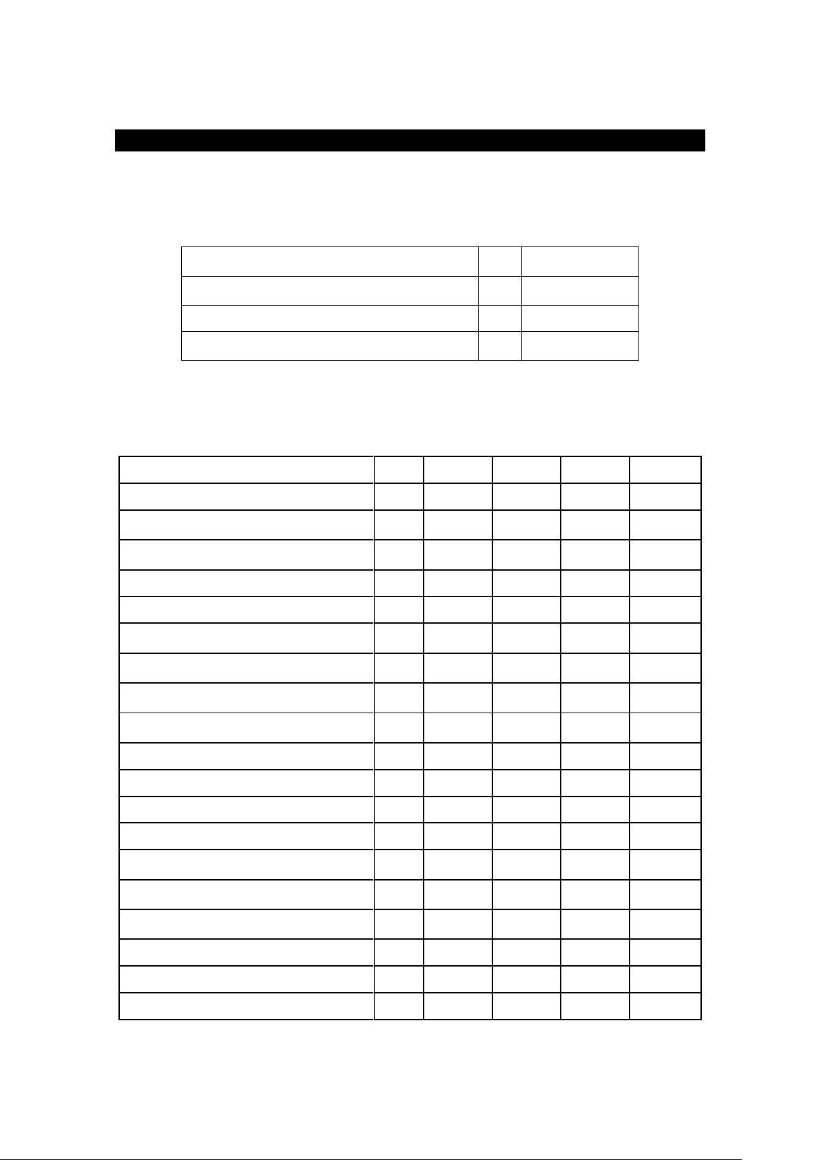
Ambient operating temperature
ºC
ºF
+5 / +41
+41 / +105.8
Storage temperature
ºC
ºF
+1 / +55
+33.8 / +131
Maximum relative humidity
%
90
Maximum altitude
m
ft
1000
3280
MODEL
EWH-25
EWH-30
EWH-40
EWH-60
DC (Drum capacity)
litres
100
130
180
250
CM (Maximum load)
Kg
Lb
10
25
13
30
18
40
25
60
PN (Net weight)
Kg
Lb
230
507
250
551
360
794
490
1080
Power of Motor
Kw.
0.75
1.5
2.2
3
Heating Power (Electrical Heating models)
Kw. 6 9
12
18
Heating Power (Hot Water Heating
models)
Kw. 2 3 4 6
Maximum Power Absorbed (Electrical
Heating models)
Kw.
6.25
9.5
12.75
19
Maximum Power Absorbed (Hot Water
Heating models)
Kw.
2.25
3.5
4.75
7
Maximum Power Absorbed (Steam and
Self-service Hot Water Heating models)
Kw.
0.75
1.5
2.2
3
Drainage diameter
Inch 3 3 3 3
Water input diameter
BSP
¾”
¾”
¾”
¾”
Steam input diameter
BSP
½”
½”
½”
¾”
Steam consumption
Kg/h 7 8.5
12
15
Static floor load
KN
Lb
2,30
507
2,50
551
3,60
793
4,90
1080
Dynamic floor load
KN
Lb
0,75
166
1,05
231
1,40
308
1,75
385
Maximum vertical load
KN
Lb
3,05
673
3,55
782
5
1101
6,65
1465
Dynamic force
Hz/N
16,7
16,7
16
15
G force
300
350
350
350
Maximum noise level
db
<70
<70
<70
<70
Main Specifications
Ambient conditions
GROUP A (High spin floating washing machines)
Page 4

GROUP B (Fast spin rigid washing machines)
MODEL
EWR-25
EWR-30
EWR-40
EWR-60
DC (Drum capacity)
Litres
100
130
180
250
CM (Maximum load)
Kg
Lb
10
25
13
30
18
40
25
60
PN (Net weight)
Kg
Lb
208
458
225
496
246
542
320
705
Power of Motor
Kw.
0.75
1.5
2.2
3
Heating Power (Electrical Heating models)
Kw. 6 9
12
18
Maximum Power Absorbed (Electrical
Heating models)
Kw.
6.25
9.5
12.75
19
Maximum Power Absorbed (Steam and
Hot Water Heating models)
Kw.
0.75
1.5
2.2
3
Drainage diameter
Inch 3 3 3 3
Water input diameter
BSP
¾”
¾”
¾”
¾”
Steam input diameter
BSP
½”
½”
½”
¾”
Steam consumption
Kg/h 7 8.5
12
15
Static floor load
KN
Lb
2,08
468
2,25
506
2,46
553
3,2
719
Dynamic floor load
KN
Lb
0,5
112
0,6
135
0,9
202 1 225
Maximum vertical load
KN
Lb
2,58
580
2,85
641
3,36
755
4,2
944
Dynamic force
Hz/N
12
12
12
12
G force
200
200
200
200
Maximum noise level
db
<70
<70
<70
<70
MODEL
EWS-25
EWS-30
EWS-40
EWS-60
EWS-80
DC (Drum capacity)
litres
100
130
180
250
400
CM (Maximum load)
Kg
Lb
10
25
13
30
18
40
25
60
35
80
PN (Net weight)
Kg
Lb
217
478
239
526
281
619
340
749
473
1042
Power of Motor
Kw.
0.75 1 1.5
2.2
3
Heating Power (Electrical Heating
models)
Kw. 6 9
12
18
21
Maximum Power Absorbed
(Electrical Heating models)
Kw.
6.25
9.3
12.5
18.75
22
Maximum Power Absorbed (Steam
and Hot water heating models)
Kw.
0.75 1 1.5
2.2
3
Drainage diameter
Inch 3 3 3 3
3
Water input diameter
BSP
¾”
¾”
¾”
¾”
¾”
Steam input diameter
BSP
½”
½”
½”
¾”
¾”
Steam consumption
Kg/h 7 8.5
12
15
18
GROUP C (Standard spin rigid washing machines)
Page 5

MODEL
Unit
EWS-25
EWS-30
EWS-40
EWS-60
EWS-80
Static floor load
KN
Lb
2,17
478
2,39
526
2,81
619
3,40
749
4,73
1042
Dynamic floor load
KN
Lb
0,3
66
0,35
77
0,45
99
0,6
132
0,8
176
Maximum vertical load
KN
Lb
2,47
544
2,74
603
3,26
718 4 881
5,53
1218
Dynamic force
Hz/N
17.8
17.8
16.7
16
15
G force
100
100
100
100
100
Maximum noise level
db
<70
<70
<70
<70
<70
Page 6
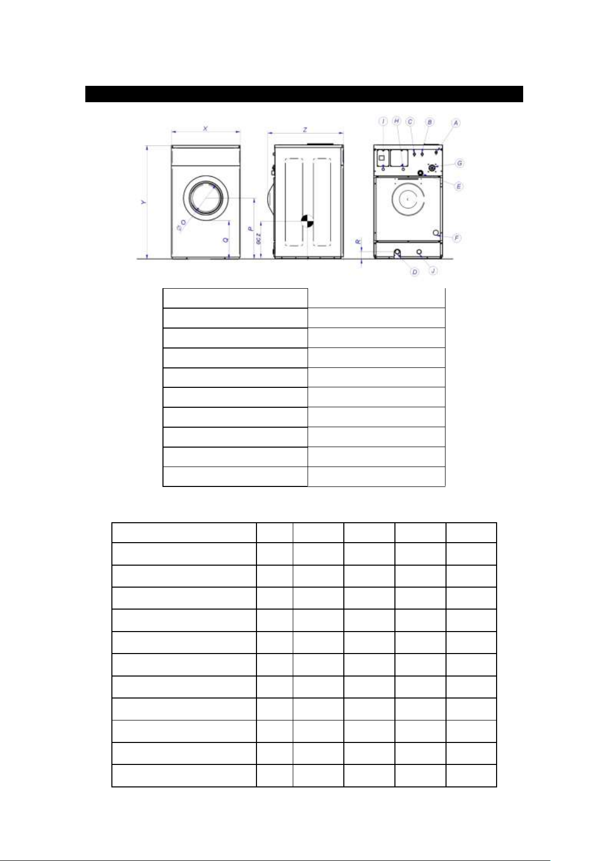
A (Cold water input)
29-58 psi (2-4 bar)
B (Hot water input)
29-58 psi (2-4 bar)
C (Aux water input)
29-58 psi (2-4 bar)
D (Drainage)
E (Steam output)
F (Steam input)
29-58 psi (2-4 bar)
G (Dispenser inlet)
H (Dispenser electric hose input)
I (Main electric hose input)
J (Drainage Nº2 – optional)
MODEL
Unit
EWH-25
EWH-30
EWH-40
EWH-60
M (Drum diameter)
mm
Inch
532
20.94
620
24.41
700
27.56
770
30.31
N (Drum depth)
mm
Inch
425
16.73
430
16.93
470
18.5
530
20.86
O (Entrance diameter)
mm
Inch
290
11.41
373
14.7
373
14.7
373
14.7
P (Distance center of the drum)
mm
Inch
630
24.8
695
27.36
742
29.21
850
33.46
Q (Distance to the door)
mm
Inch
408
16.06
427
16.81
474
18.66
610
24.02
R (Drainage position)
mm
Inch
80
3.15
80
3.15
80
3.15
100
3.94
X (Width)
mm
Inch
692
27.24
790
31.10
885
34.84
979
38.54
Y (Height)
mm
Inch
1160
45.67
1300
51.18
1410
55.51
1562
61.5
Z (Depth)
mm
inch
825
32.48
870
34.25
915
36.02
1042
41.02
GC Y (Gravity centre)
mm
inch
424
16.69
398
15.67
464
18.27
503
19.8
GC Z (Gravity centre)
mm
inch
577
22.72
651
25.63
702
27.64
773
30.43
GR A-B-C
Main Dimensions
GROUP A (High spin floating washing machines)
Page 7

MODEL
Unit
EWR-25
EWR-30
EWR-40
EWR-60
M (Drum diameter)
mm
Inch
532
20.94
620
24.41
620
24.41
700
27.56
N (Drum depth)
mm
Inch
425
16.73
430
16.93
580
22.83
670
26.38
O (Entrance diameter)
mm
Inch
290
11.41
373
14.7
373
14.7
373
14.7
P (Distance center of the drum)
mm
Inch
630
24.8
695
27.36
695
27.36
742
29.21
Q (Distance to the door)
mm
Inch
408
16.06
427
16.81
427
16.81
474
18.66
R (Drainage position)
mm
Inch
80
3.15
80
3.15
80
3.15
100
3.94
X (Width)
mm
Inch
692
27.24
790
31.10
790
31.10
885
34.84
Y (Height)
mm
Inch
1160
45.67
1300
51.18
1300
51.18
1410
55.51
Z (Depth)
mm
inch
825
32.48
870
34.25
1040
40.94
1100
43.31
GC Y (Gravity centre)
mm
inch
425
16.73
419
16.5
510
20.08
638
25.12
GC Z (Gravity centre)
mm
inch
485
19.09
518
20.4
551
21.7
667
25.26
MODEL
Unit
EWS-25
EWS-30
EWS-40
EWS-60
EWS-80
M (Drum diameter)
mm
Inch
620
24.41
620
24.41
700
27.56
770
30.31
860
33.86
N (Drum depth)
mm
Inch
330
12.99
430
16.93
470
18.5
530
20.86
600
23.62
O (Entrance diameter)
mm
Inch
373
14.7
373
14.7
373
14.7
373
14.7
560
22.05
P (Distance center of the drum)
mm
Inch
568
22.36
568
22.36
654
25.75
654
25.75
733
28.86
Q (Distance to the door)
mm
Inch
310
12.20
310
12.20
396
15.59
396
15.59
373
14.7
R (Drainage position)
mm
Inch
135
5.31
135
5.31
95
3.74
135
5.31
135
5.31
X (Width)
mm
Inch
719
28.31
719
28.31
788
31.02
885
34.84
979
38.54
Y (Height)
mm
Inch
1177
46.34
1177
46.34
1321
52.00
1321
52.00
1428
56.22
Z (Depth)
mm
inch
738
29.06
853
33.58
895
35.24
1036
40.79
1166
45.91
GC Y (Gravity centre)
mm
inch
383
15.08
484
19.06
479
18.86
591
23.27
682
26.85
GC Z (Gravity centre)
mm
inch
511
20.12
524
20.63
546
21.5
541
21.3
635
25
GROUP B (Fast spin rigid washing machines)
GROUP C (Standard spin rigid washing machines)
Page 8
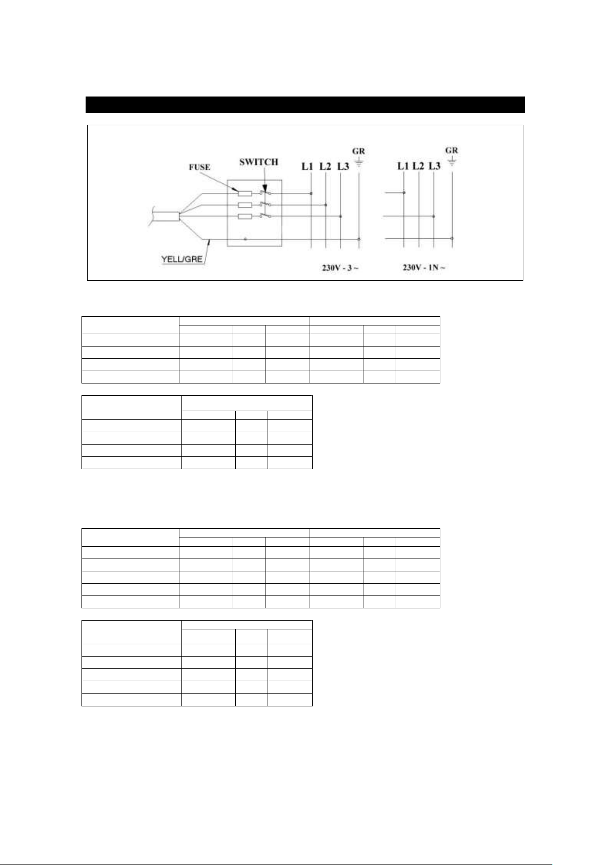
Electrical heating
230V-3~
230V-1N~
T+3x (mm²)
AWG
FUSE(A)
T+3x (mm²)
AWG
FUSE(A)
EWH-25/EWR-25
2.5
9
20 4 7
32
EWH-30/EWR-30
4 8 25
10 5 50
EWH-40/EWR-40
6 6 40
16 4 63
EWH-60/EWR-60
10 4 50
25
2
100
Hot water heating
Steam heating
230V-1N~
T+3x (mm²)
AWG
FUSE(A)
EWH-25/EWR-25
1.5
14 6 EWH-30/EWR-30
1.5
13
10
EWH-40/EWR-40
1.5
11
10
EWH-60/EWR-60
1.5
10
16
Electrical heating
230V-3~
230V-1N~
T+3x (mm²)
AWG
FUSE(A)
T+3x (mm²)
AWG
FUSE(A)
EWS-25
2.5
9
20 4 7
32
EWS-30
4 8 25
10 5 50
EWS-40
6 6 40
16 4 63
EWS-60
10 4 50
25
2
100
EWS-80
16 4 63
25
1
100
Hot water and
steam heating
230V-1N~
T+3x (mm²)
AWG
FUSE(A)
EWS-25
1.5
16 4 EWS-30
1.5
14
6
EWS-40
1.5
13
10
EWS-60
1.5
11
10
EWS-80
1.5
10
16
Electrical Specifications
GROUP A-B (High spin floating washing machines and Fast spin rigid washing machines)
GROUP C(Standard spin rigid washing machines)
Page 9
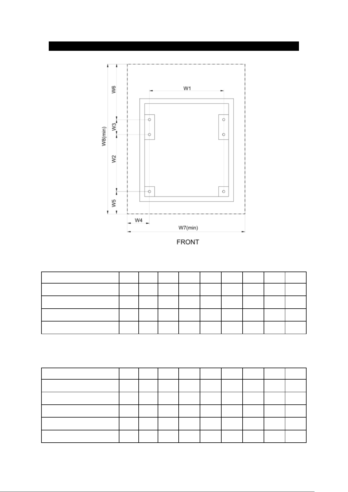
Rigid Washing Machines
MODEL
Unit
W1
W2
W3
W4
W5
W6
W7
W8
EWR-25
Inch
mm
19.69
500
16.42
417
4.72
120
3.78
96
3.89
99
6.10
155
27.24
692
31.13
791
EWR-30
Inch
mm
23.46
596
16.30
414
4.72
120
3.78
96
3.74
95
9.49
241
31.02
788
34.25
870
EWR-40
Inch
mm
23.46
596
18.07
459
4.72
120
3.78
96
8.03
204
9.9
251
31.02
788
40.73
1034
EWR-60
Inch
mm
27.24
692
21.38
543
4.72
120
3.78
96
8.01
203
10.1
257
34.8
884
44.23
1123
MODEL
Unit
W1
W2
W3
W4
W5
W6
W7
W8
EWS-25
Inch
mm
19.69
500
11.85
301
5.87
149
4.31
109.5
5.61
142.5
5.85
148.5
28.31
719
29.18
741
EWS-30
Inch
mm
19.69
500
12.01
305
9.13
232
4.31
109.5
6.79
172.5
5.85
148.5
28.31
719
33.78
858
EWS-40
Inch
mm
22.05
560
14.49
368
9.13
232
4.49
114
5.83
148
5.79
147
31.03
788
35.24
895
EWS-60
Inch
mm
24.41
620
15.24
387
11.81
300
5.20
132
7.68
195
6.22
158
34.81
884
40.95
1040
EWS-80
Inch
mm
27.56
700
19.29
490
11.81
300
5.49
139.5
7.64
194
6.22
158
38.54
979
44.96
1142
GROUP B (Fast spin rigid washing machines)
GROUP C (Standard spin rigid washing machines)
Page 10

1. CONTENTS
1. CONTENTS ............................................................................................................................................................... 1
2. INTRODUCTION ....................................................................................................................................................... 2
3. IMPORTANT INSTRUCTIONS REGARDING SAFETY AND USE ........................................................................... 3
4. STANDARDS ............................................................................................................................................................. 5
5. TRANSPORT ............................................................................................................................................................. 5
6. CHARACTERISTICS OF THE PLACE OF INSTALLATION ..................................................................................... 5
7. HANDLING ................................................................................................................................................................ 5
8. INSTALLATION (ALL MODELS) ............................................................................................................................... 6
8.1. Water connection .............................................................................................................................................. 6
8.2. Steam connection.............................................................................................................................................. 6
8.3. Drainage ............................................................................................................................................................ 6
8.4. Electrical connection ......................................................................................................................................... 7
8.5. Dispenser connection ........................................................................................................................................ 7
9. INSTALLATION OF RIGID WASHING MACHINES (GROUPS B-C)........................................................................ 8
9.1. Using anchorage base ...................................................................................................................................... 9
9.2. Installation of the washer-extractor without anchorage base ............................................................................ 9
9.2.1. Using expansion bolts ............................................................................................................................... 9
9.2.2. Using J-bolts ............................................................................................................................................ 10
10. INSTALLATION OF SELF-SERVICE WASHING MACHINES (GROUP A-B-C) ............................................... 11
10.1. Pay centre ....................................................................................................................................................... 11
10.2. Card ................................................................................................................................................................. 11
10.3. Coin ................................................................................................................................................................. 11
1
Page 11

2. INTRODUCTION
Dear customer,
Thank you for the confidence you have placed in our product. We hope it meets your needs.
The guarantee does not cover damage to glass components, or consumables (seals, bulbs, etc.) nor damage to
insulation material or damage due to the incorrect installation of the appliance, or to inappropriate use, inadequate
maintenance or poor repair processes.
This appliance is subject to changes and modifications for its technical progress.
Retain This Manual In A Safe Place For Future Reference
American Dryer Corporation products embody advanced concepts in engineering, design, and safety. If this product
is properly maintained, it will provide many years of safe, efficient, and trouble free operation.
ONLY qualified technicians should service this equipment.
OBSERVE ALL SAFETY PRECAUTIONS displayed on the equipment or specified in the installation manual included
with the dryer.
The following “FOR YOUR SAFETY” caution must be posted near the dryer in a prominent location.
FOR YOUR SAFETY
Do not store or use gasoline or other flammable vapors and liquids in the vicinity of this or any other appliance.
POUR VOTRE SÉCURITÉ
Ne pas entreposer ni utiliser d’essence ni d’autres vapeurs ou liquides inflammables à proximité de cet appareil ou de
tout autre appareil.
We have tried to make this manual as complete as possible and hope you will find it useful. ADC reserves the right to
make changes from time to time, without notice or obligation, in prices, specifications, colors, and material, and to
change or discontinue models. The illustrations included in this manual may not depict your particular dryer exactly.
IMPORTANT
For your convenience, log the following information:
DATE OF PURCHASE __________________________________________ MODEL NO. ______________________
RESELLER’S NAME _____________________________________________________________________________
Serial Number(s) ________________________________________________________________________________
______________________________________________________________________________________________
______________________________________________________________________________________________
Replacement parts can be obtained from your reseller or the ADC factory. When ordering replacement parts from the
factory, you can FAX your order to ADC at (508) 678-9447 or telephone your order directly to the ADC Parts
Department at (508) 678-9000. Please specify the dryer model number and serial number in addition to the
description and part number, so that your order is processed accurately and promptly.
2
Page 12

3. IMPORTANT INSTRUCTIONS REGARDING SAFETY AND USE
WARNING: To reduce the risk of electrical shocks
or injury when using the appliance, the basic
precautions should be observed, including the
following:
1-READ all the instructions prior to using the
appliance and KEEP THEM in an easily
accessible place for reference in the event
of doubt.
2- This appliance must be installed by an
Official or authorised Technical Assistance
Service. The installation, incorrect
adjustment, inappropriate maintenance or
use of the appliance may cause material
damages and injuries. Before
commissioning the appliance, carefully read
the instructions contained in this manual.
These contain important information about
the installation of the appliance
3- The incorrect installation, inappropriate
servicing, poor maintenance and/or
cleaning and modifications to the appliance
may cause damage to both the appliance
and the users.
4-Failure to comply with the given procedures
will result in the loss of cover under
guarantee.
5-Switch off the appliance in the event of
breakdown or faulty operation.
67-Do not wash clothes which have been
previously treated, washed, soaked or
stained with petrol, dry cleaning solvents, or
other inflammable or explosive substances,
as these give off vapours which may catch
fire or explode.
8-Do not add petrol, dry cleaning solvents or
other inflammable substances to the
washing water. These substances give off
vapours which could catch fire or explode.
9-In some conditions, hydrogen gas may be
produced in a hot water system which has
not been used for more than two weeks.
HYDROGEN GAS IS EXPLOSIVE. If the
hot water system has not been used for a
while, before using the washing machine
turn on all the hot water taps and let the
water run for a few minutes. This will
release any accumulated hydrogen gas. As
the gas is inflammable, do not smoke or
use naked flames during this operation.
10-Do NOT allow children to play in or on the
appliance. Children should be strictly
supervised when in the vicinity of a machine
which is operating.
11-Remove the door from the appliance before
disposal or before leaving it out of service.
12-DO NOT TRY TO OPEN THE DOOR if the
drum is moving.
13-Do NOT install or store the appliance in the
open.
14-Do NOT try to force the controls.
15-Do not repair or replace parts of the
appliance or carry out any servicing unless
recommended to do so in the User
Instruction Manual. Make sure that you fully
understand the instructions and have the
necessary skills to carry out the operations
described.
16-Do NOT remove any safety device or modify
any components in the washing machine.
DO NO INSTALL components not
belonging to the machine in the appliance.
17-Failure to comply with any of the instructions
given in the Instruction Manual may result in
personal injury to the user. It is no possible
to provide for all possible situations and
contingencies with warnings about risk and
hazards. Therefore, any person involved in
the transportation, installation, use or
maintenance of the machine should always
employ common sense, caution and care.
18-Do NOT use the machine unless all the
covers and guards are correctly fitted and
secured.
19-The distributor (vendor) MUST correctly
instruct the user during commissioning.
20-Pour the correct doses of detergent, fabric
softener and bleach into the dispenser
drawer, as indicated by the manufacturer.
Heed tips concerning the treatment of
different materials given by the
manufacturers.
21-Remove any traces of detergent or liquids
from the dispenser drawer everyday. Never
use powdered or abrasive detergents for
cleaning; use only water and soap.
22-Clean the water inlet filters and the external
dispenser conducts once a month.
3
Page 13

23-Never clean the exterior by water injection;
functional parts of the machine could
damage.
24-If the washing machine is to be idle for long
periods, apply a coat of Vaseline oil to all its
stainless steel surfaces.
25-An annual general revision is recommended
KEEP THESE INSTRUCTIONS SAFELY
ENGLISH
WARNING! Repairs or work carried out by personnel
not belonging to the authorised Technical Service will
result in the loss of cover under guarantee.
CAUTION! Fire protection regulations must be strictly
observed.
WARNING! Before starting to connect the appliance,
check that the installation values match those given on
the appliance specification plate.
4
Page 14

ENGLISH
4. STANDARDS
All models comply to standard EN ISO 10472 concerning the safety requirements for industrial laundry machinery.
2006/42/EC Machinery Safety Directive
2006/95/EC Low Voltage
2004/108/EC Electromagnetic Compatibility Directive
UL Standard for Electric Clothes Washing Machines and Extractors; UL 2157 and CSA C22.2 No. 169
For models with a drum capacity of less than 120 dm3 (4.24 cu.ft):
Standards EN 60335-1 and EN 60335-2-7 concerning Electrical appliances.
Standards EN 55014, EN 61000-3-2 and EN 61000-3-3 on Electromagnetic compatibility.
For models with a larger capacity:
Standard EN 60204-1 concerning Electrical appliances.
Standards EN 61000-6-1, EN 61000-6-3 y EN 61000-3-1 on Electromagnetic compatibility.
5. TRANSPORT
When transporting the appliance, the following should be observed:
o Current regulations and laws
o Regulations concerning occupational risk prevention
o Regulations concerning safety during transport
Check the delivery is in good condition prior to receipt.
6. CHARACTERISTICS OF THE PLACE OF INSTALLATION
As established in current legislation, an omnipolar switch must be installed between the appliance and the mains
electricity supply with a minimum distance of 3 mm for each pole between contacts.
The washing machine must be firmly secured on the floor, which will support its weight and the residual force
generated while spinning.
The washing machine must be correctly levelled leaving spaces to make maintenance easier, 0.5 m on the side and 1
m at the rear.
WARNING! The stopcocks should be close to the appliance in an easily accessible location.
7. HANDLING
When handling the appliance, the following should be observed:
o Current regulations and laws
o Regulations concerning occupational risk prevention
- Safety clothing and gloves must be worn for protection against cuts and knocks and safety shoes should be
used to prevent against injury as a result of falling components.
- When handling and moving the appliance, appropriate tools and resources must be used.
- Any work to the interior of the appliance must be carried out by qualified and skilled personnel.
CAUTION! Inappropriate handling of the appliance may result in damage or injury.
5
Page 15

ENGLISH
Fig. 3
Fig. 4
Fig. 5
A=Stopcock
B=Filter
A=Stopcock B=Filter C=Hose A.C.=Hot water A.F.=Cold water A.D.=Decalcified water
A= Drainage pipe bend
B=Clamp
Warning!
Failure to fit the filters on the water and steam
inputs will result in loss of cover under
guarantee for the corresponding components
8. INSTALLATION (ALL MODELS)
8.1.Water connection
If only cold water is available, connect as shown in figure 3. Where hot water is available, connect as shown in figure
4. If, in addition, decalcified water is available, connect as shown in figure 5
Required dynamic pressure: 2 ÷ 4 Kg/cm2 .
VERY IMPORTANT: Bleed water circuit prior to installation and fitting filters.
8.2.Steam connection
If steam is available, the water will be heated by direct injection.
The connection diagram is shown in the figure.
Steam pressure: 2 ÷ 4 Kg/cm2 .
VERY IMPORTANT: Bleed steam circuit prior to installation and fitting filters
After steam has been introduced into the machine for the first time, it is advisable for the steam hose nuts to be retightened.
8.3.Drainage
Fix the drainage bend pipe as shown in the figure
6
Page 16

ENGLISH
8.4.Electrical connection
WARNING: Risk of electrical shock
To access the connection strip, remove the switch cover and attach the hose cable to the rear panel. In large capacity
models (group D) the electrical connections are located in the rear cabinet, the circuit breaker must be set to “0” in
order to open the door
Connect the terminal strip and check that the connections correspond to the operating voltage.
Place an autonomous power switch (I) at the current input, with a minimum of 3 mm between contacts. Fit a 300mA,
type A, immediate response differential protection.
INSTRUCTIONS FOR CONNECTING THE EARTH
This appliance must be connected to an earthed metal, permanent wiring system, or an earth conductor should be
installed with the circuit conductors and connected to the earth discharge terminal or the appliance cable.
Connect the terminal strip and check that the connections correspond to the operating voltage.
Fit a 300mA, type A, immediate response differential protection.
The machine must be connected to earth.
If the voltage frequency is 60 Hz, change the drainage valve connection.
8.5. Dispenser connection
1: 230 V electrical signal. For dispenser 1 (prewash)
2: 230 V electrical signal. For dispenser 2 (wash)
3: 230 V electrical signal. For dispenser 3 (bleach)
4: 230 V electrical signal. For dispenser 4 (softener)
5: 230 V electrical signal. For dispenser 5 (ONLY PROGRAMMABLE MODELS)
6: 230 V electrical signal. For dispenser 6 (ONLY PROGRAMMABLE MODELS)
7: 230 V electrical signal. For dispenser 7 (ONLY PROGRAMMABLE MODELS)
7
Page 17

ENGLISH
EWR-25
EWR-30
EWR-40
EWR-60
Static floor load (kN - lb)
2,08 - 468
2,25 - 506
2,46 - 553
3,2 - 678
Dinamic floor load (Kn - lb)
0,5 - 112
0,6 - 135
0,9 - 202
1 - 225
Maximum vertical load (kN - lb)
2,58 - 580
2,85 - 641
3,36 - 755
4,2 - 944
Dinamic load frequency (Hz)
12
12
12
12
G factor
200
200
200
200
EWS-25
EWS-30
EWS-40
EWS-60
EWS-80
Static floor load (kN - lb)
2,17 - 478
2,39 - 526
2,81 - 619
3,40 - 749
4,73 - 1042
Dinamic floor load (Kn - lb)
0,3 - 66
0,35 - 77
0,45 - 99
0,6 - 132
0,8 - 176
Maximum vertical load (kN - lb)
2,47 - 538
2,74 - 603
3,26 - 718
4 - 881
5,53 - 1218
Dinamic load frequency (Hz)
12
12
12
12
12
G factor
100
100
100
100
100
9. INSTALLATION OF RIGID WASHING MACHINES (GROUPS B-C)
Forces transmitted by the washing machine
WARNING! Rigid washing machines must not be installed on non-foundation floors without authorisation
from a technician familiar with the structure and resistance of the building.
Please check the weight of the machine plus the dynamic forces generated during spinning. The
manufacturer does not accept responsibility for any damage due to vibration in this type of installation.
The anchorage base IS SOLD SEPARATELY.
WARNING! RIGID MACHINES MUST BE ANCHORED TO THE FLOOR. Correct construction of the anchorage
to the floor is essential to ensure the correct working of the appliance and to prevent serious damage to the
structure of the machine
8
Page 18

ENGLISH
minimun resistance=25N/mm2 (3600psi)
9.1.Using anchorage base
Before mounting the base, a portion of the floor larger than the maximum area of the base must be lifted from the
floor, so that the hole depth dimensions are greater than those of the surface. Then, the anchor support must be
placed inside the hole with studs upwards, and the hole must be filled with concrete until the thread of the studs
protrudes over the concrete surface (figure 3), which must be smooth and flat. It is advisable to cover the threads with
adhesive tape so as to prevent the concrete from adhering to the surface.
It is extremely important to secure the anchor supports firmly by making sure the front part of these supports matches
up with the front part of the washing machine, and maintaining the minimum distance between the supports and the
wall or other appliances so as to facilitate maintenance.
Once the concrete has set properly, the washing machine can be placed in its final position by tightening the nuts and
the associated spacers in the bolts and making sure the machine is suitably levelled.
For the measurements of each appliance, please refer to the “Rigid washing machines” chart.
9.2.Installation of the washer-extractor without anchorage base
9.2.1. Using expansion bolts
Before anchoring the machine to the floor, make sure that its minimum resistance is equal or higher than 3600 psi
(25N/mm2).
First mark the points at which the holes are to be made, using the dimensions specified in the “Rigid washing
machines” chart.
Next make holes to a depth, at minimum, equal to 3,9 inch (100mm). Clean the holes with compressed air.
Place the washer-extractor in position over the holes, then insert the expansion bolts in the holes. Be sure to use M16
expansion bolts, and that they protrudes above the surface by 2,4 inch (60mm). Once in place, tighten the bolts until
the machine is securely fastened.
9
Page 19

ENGLISH
9.2.2. Using J-bolts
Before anchoring the machine to the floor, make sure that its minimum resistance is equal or higher than 3600 psi
(25N/mm2).
First mark the points at which the holes are to be made, using the dimensions specified in the plans on page 12.
Next make holes to a depth, at minimum, equal to 3,9 inch (100mm). Make the holes big enough to insert the J-bolt
and clean using compressed air. Insert the J-bolts in the holes and secure using a suitable anchoring compound,
ensuring that the bolt protrudes above the surface by 2,4 inch (60mm). Be sure to use M16 J- bolts.
Place the washer-extractor in position above the bolts, and gradually tighten the nuts one after another until the
machine is securely fastened.
Check the condition of the J-bolts one week after installation.
10
Page 20

ENGLISH
Coin kit
Card kit
10. INSTALLATION OF SELF-SERVICE WASHING MACHINES (GROUP A-B-C)
10.1. Pay centre
Self-service machines are delivered with this configuration, i.e. they are ready for connection to a pay centre. The pay
centre receives an electrical signal from the washing machine informing of its availability and, at the same time, the
washing machine receives the signal that the correct money has been inserted and the programme may be run. The
price and currency settings are external to the washing machine and can therefore not be programmed. Please see
the user manual for details on self-service configuration.
10.2. Card
If you have obtained the "card kit" it can be installed in the machine following the instructions supplied with the kit,
remove the cover to the right of the controls and insert the "card kit" in its place. To access the fastenings, remove the
top cover of the machine.
Once installed, the machine operates in almost the same way as the pay centre machine, prices and currency are
programmed on the card reader. Please see the user manual for details on self-service configuration.
10.3. Coin
If you have obtained the “coin kit” this can be installed in the machine by following the instructions supplied with the
kit. Remove the cover to the right of the controls and fit the "card kit" in its place. To access the fastenings, remove the
top cover of the machine.
Once installed, programme the currency and price settings for each programme. Please see the user manual for
instructions on self-service configuration.
¡WARNING! The installation of the different self-service kits involves working with electrical components.
Switch off the machine before any work.
Work carried out by personnel not belonging to the authorised Technical Service will result in the loss of
cover under guarantee.
11
Page 21

ESPAÑOL
SIMBOLO
SIGNIFICADO
GROUP A (High spin floating washing machines)
GRUPO A (LAVADORAS FLOTANTE DE CENTRIFUGADO ALTO)
GROUP B (Fast spin rigid washing machines)
GRUPO B (LAVADORAS RIGIDAS DE CENTRIFUGADO RAPIDO)
GROUP C (Standard spin rigid washing machines)
GRUPO C (LAVADORAS RIGIDAS DE CENTRIFUGADO ESTANDAR)
DC (Drum capacity)
CAPACIDAD DEL TAMBOR
CM (Maximum load)
CARGA MAXIMA
PN (Net weight)
PESO NETO
A (Cold water input)
ENTRADA AGUA FRIA
B (Hot water input)
ENTRADA AGUA CALIENTE
C (Aux water input)
ENTRADA AGUA AUX
D (Drainage)
DESAGUE nº1
E (Steam output)
SALIDA DE VAHOS
F (Steam input)
ENTRADA VAPOR
G (Dispenser inlet)
TOMA DE DOSIFICACION
H (Dispenser electric hose input)
ENTRADA MANGUERA ELECTRICA DOSIFICACION
I (Main electric hose input)
ENTRADA MANGUERA ELECTRICA PRINCIPAL
J (Drainage Nº2 – optional)
DESAGUE nº2 (OPCIONAL)
M (Drum diameter)
DIAMETRO TAMBOR
N (Drum depth)
PROFUNDIDAD TAMBOR
O (Entrance diameter)
DIAMETRO BOCA
P (Distance center of the drum)
DISTANCIA AL CENTRO DEL TAMBOR
Q (Distance to the door)
DISTANCIA A LA PUERTA
R (Drainage position)
POSICION DEL DESAGÜE
X (Width)
ANCHO
Y (Height)
ALTURA
Z (Depth)
PROFUNDIDAD
Power of motor
POTENCIA MOTOR
Heating power
POTENCIA CALENTAMIENTO
Maximum power absorbed (Electrical heating models)
POTENCIA MAXIMA ABSORBIDA (MODELOS CALENTAMIENTO
ELECTRICO)
Maximum power absorbed (Hot water and steam models)
POTENCIA MAXIMA ABSORBIDA (MODELOS CALENTAMIENTO VAPOR O
AGUA CALIENTE)
Drainage diameter
DIAMETRO DESAGÜE
Water input diameter
DIAMETRO ENTRADAS DE AGUA
Steam input diameter
DIAMETRO ENTRADA VAPOR
Dynamic force
FUERZA DINAMICA
INTERPRETACION DE TABLAS: SIMBOLOS Y VALORES
1
Page 22

ESPAÑOL
1. INDICE
1. INDICE ....................................................................................................................................................................... 2
2. INTRODUCCIÓN ....................................................................................................................................................... 3
3. INSTRUCCIONES IMPORTANTES DE SEGURIDAD Y USO ................................................................................. 4
4. NORMAS ................................................................................................................................................................... 6
5. TRANSPORTE .......................................................................................................................................................... 6
6. CARACTERÍSTICAS DEL LUGAR DE INSTALACIÓN ............................................................................................ 6
7. MANIPULACION ........................................................................................................................................................ 6
8. INSTALACION (TODOS LOS MODELOS) ............................................................................................................... 7
8.1. Conexión de agua ............................................................................................................................................. 7
8.2. Conexión de vapor ............................................................................................................................................ 7
8.3. Desagüe ............................................................................................................................................................ 7
8.4. Conexión eléctrica ............................................................................................................................................. 8
8.5. Conexión dosificadores ..................................................................................................................................... 8
9. INSTALACIÓN LAVADORAS RIGIDAS (GRUPO B-C) ............................................................................................ 9
9.1. Instalación de la lavadora con base de anclaje .............................................................................................. 10
9.2. Instalación de la lavadora sin base de anclaje ............................................................................................... 10
9.2.1. Mediante tornillos de expansión .............................................................................................................. 10
9.2.2. Mediante pernos J ................................................................................................................................... 11
10. INSTALACIÓN LAVADORAS AUTOSERVICIO (GRUPO A-B-C) ..................................................................... 12
10.1. Central de pago ............................................................................................................................................... 12
10.2. Tarjeta ............................................................................................................................................................. 12
10.3. Coin ................................................................................................................................................................. 12
2
Page 23

ESPAÑOL
2. INTRODUCCIÓN
Estimado cliente:
Gracias por haber depositado su confianza en nuestro producto. Deseamos que responda a sus necesidades.
Las condiciones de garantía no cubren daños de componentes de cristal, ni repuestos consumibles (juntas,
bombillas, etc.) como tampoco el deterioro del material aislante o daños imputables a una instalación incorrecta del
aparato, a su utilización en una aplicación indebida, a un mantenimiento inadecuado o a procesos de reparación
deficientes.
Este aparato está sujeto a cambios y modificaciones que apoyen su progreso técnico.
Guarde Este Manual En Un Lugar Seguro Como Referencia Para El Futuro
Los productos American Dryer Corporation están realizados siguiendo avanzadas pautas en ingeniería, diseño y
seguridad. Si este producto se utiliza adecuadamente, ofrecerá muchos años de uso seguro, eficiente y libre de
problemas.
SOLO los técnicos de mantenimiento cualificados deberían realizar reparaciones en esta máquina.
LEA ATENTAMENTE TODAS LAS RECOMENDACIONES DE SEGURIDAD presentes en la máquina o
especificadas en el manual de instalación.
La siguiente advertencia deberá ser colocada cerca de la máquina en un lugar visible.
FOR YOUR SAFETY
Do not store or use gasoline or other flammable vapors and liquids in the vicinity of this or any other appliance.
POUR VOTRE SÉCURITÉ
Ne pas entreposer ni utiliser d’essence ni d’autres vapeurs ou liquides inflammables à proximité de cet appareil ou de
tout autre appareil.
Hemos intentado hacer este manual tan complete como ha sido posible y esperamos que lo encuentre útil. ADC se
reserva el derecho de realizar cambios eventualmente, sin aviso previo u obligación, en precios, especificaciones,
colores y materiales, y de cambiar o retirar modelos. Las ilustraciones incluidas en este manual podrían no
representar exactamente su máquina.
IMPORTANTE
Para su conveniencia, rellene la siguiente información:
FECHA DE COMPRA _________________________________________ MODELO NO. ______________________
NOMBRE DEL DISTRIBUIDOR _____________________________________________________________________
Número(s) de serie ______________________________________________________________________________
______________________________________________________________________________________________
Piezas de recambio pueden ser obtenidas a través de su distribuidor o la fábrica ADC. Si realiza un pedido de
recambios a la fábrica, puede hacer su pedido via FAX al (508) 678-9447 o por teléfono en el Departamento de
Recambios de ADC en el (508) 678-9000. Por favor, especifique el número de modelo y el número de serie de la
máquina junto con la descripción y la referencia de la pieza, para que su pedido pueda ser procesado de forma rápida
y correcta.
3
Page 24

3. INSTRUCCIONES IMPORTANTES DE SEGURIDAD Y USO
ADVERTENCIA: Para reducir el riesgo de
descargas eléctricas o lesiones personales al
usar su aparato, siga las precauciones
básicas, incluyendo las siguientes:
1-LEA todas las instrucciones antes de usar el
aparato y GUARDELAS en lugar fácilmente
accesible para solventar cualquier duda.
2- Este aparato debe ser instalado por un Servicio
de Asistencia Técnica Oficial ó autorizado. La
instalación, ajuste incorrecto, el servicio ó
mantenimiento inapropiados del aparato así
como la manipulación inadecuada del mismo
pueden provocar daños materiales y/o
lesiones. Antes de proceder a la puesta en
servicio del aparato, lea detenidamente las
instrucciones de este manual. Encontrará
información importante acerca de su
instalación
3- La instalación incorrecta, un servicio
inadecuado, mantenimiento y/o limpieza
deficientes así como la reforma del aparato
puede provocar daños tanto al aparato como a
sus usuarios.
4-El incumplimiento de las pautas de actuación
marcadas supone la pérdida de cualquier
garantía.
5-Desconecte el aparato en caso de avería o
desperfectos de funcionamiento.
67-NO lave prendas que hayan sido previamente
tratadas, lavadas, remojadas o manchadas
con gasolina, disolventes de limpieza en seco,
u otras sustancias inflamables o explosivas,
ya que despiden vapores que pueden
incendiarse o explotar.
8-NO agregue gasolina, disolventes de limpieza
en seco, u otras sustancias inflamables al
agua de lavado. Estas substancias emiten
vapores que pueden incendiarse o explotar.
9-En determinadas condiciones, el gas de
hidrógeno puede ser producido en un sistema
de agua caliente que no se ha utilizado
durante dos semanas o más. EL GAS
HIDROGENO ES EXPLOSIVO. Si el sistema
de agua caliente no ha sido usado por un
período, antes de usar la lavadora, abra todos
los grifos de agua caliente y deje que el agua
de cada uno corra durante varios minutos.
Esto liberará el gas hidrógeno acumulado.
Como el gas es inflamable, no fume ni use
una llama durante este tiempo.
ESPAÑOL
10-NO permita que los niños jueguen en o sobre
el aparato. Mantenga a los niños bajo estricta
vigilancia cuando se encuentren en las
proximidades de una maquina en
funcionamiento.
11-Quite la puerta antes de desechar el aparato o
dejarlo fuera de servicio.
12-NO INTENTE ABRIR LA PUERTA si el tambor
está en movimiento.
13-NO instale ni almacene el aparato a la
intemperie.
14-NO trate de forzar los controles.
15-No repare o reemplace ninguna pieza del
aparato ni intente ninguna operación de
servicio a menos que se recomiende en el
manual de instrucciones de usuario. Aún así
asegúrese siempre de entender
perfectamente las instrucciones y tenga las
habilidades necesarias para llevar a cabo la
operación.
16-NO eliminar nigún dispositivo de seguridad ni
modificar ningún elemento de la lavadora. NO
INSTALAR en el interior de la maquina
elementos ajenos a ella.
17-Cualquier omisión de las indicaciones descritas
en los manuales de instrucciones, pueden
ocasionar daños personales al usuario. No es
posible cubrir todas las condiciones y
situaciones posibles con los avisos de peligro
y advertencias. Por lo tanto, el sentido
común, precaución y el cuidado son factores
que deben ser aportados por la(s) persona(s)
que transporte, instale, utilice o mantenga la
maquina.
18-NO utilizar la maquina sin estar todas las tapas
y protecciones correctamente colocadas y
fijadas.
19-ES OBLIGATORIO la instrucción correcta del
usuario por parte del distribuidor (vendedor)
durante la puesta en marcha.
20-Aporte a las cubetas correspondientes las
dosis de detergente, suavizante y lejía
indicadas por el fabricante. Observar los
consejos de tratamiento de cada tejido
indicados por el fabricante del mismo.
21-Limpie diariamente las cubetas de detergente y
líquidos. Para la limpieza use agua y jabón,
nunca detergentes abrasivos.
4
Page 25

22-Limpie mensualmente los filtros de las
entradas de agua y los conductos de
dosificación exteriores.
23-No lave nunca el exterior utilizando chorro de
agua; pueden estropearse las partes
funcionales de la máquina.
24-Si la lavadora no va a utilizarse en un período
de tiempo largo, pase una mano de aceite de
vaselina sobre todas las superficies de acero
inoxidable.
25-Se recomienda una revisión general anual
GUARDE ESTAS INSTRUCCIONES
ESPAÑOL
¡ATENCION! Las reparaciones o manipulaciones
realizadas por personal ajeno al Servicio de Asistencia
Técnica autorizado conllevan una pérdida de la
garantía.
¡CUIDADO! Aténgase estrictamente a las normas de
protección contra incendios.
¡ATENCION! Antes de emprender cualquier operación
de conexión averigüe la correspondencia entre los
valores de la instalación y las indicadas en la placa de
características del aparato, al objeto de comprobar si
el aparato corresponde a los valores de la instalación.
5
Page 26

ESPAÑOL
4. NORMAS
Todos los modelos cumplen con la norma EN ISO 10472 sobre Requisitos de seguridad para la maquinaria de
lavandería industrial.
2006/42/EC Directiva de Máquinas
2006/95/EC Baja Tensión
2004/108/EC Compatibilidad Electromagnética
Norma UL para Lavadoras Eléctricas; UL 2157 y CSA C22.2 Nº 169
Para modelos con capacidad de tambor menor de 120dm3 (4.24 cu.ft.):
Normas EN 60335-1 y EN 60335-2-7 sobre Equipamientos eléctricos.
Normas EN 55014, EN 61000-3-2 y EN 61000-3-3 sobre Compatibilidad electromagnética.
Para modelos de mayor capacidad:
Norma EN 60204-1 sobre Equipamientos eléctricos.
Normas EN 61000-6-1, EN 61000-6-3 y EN 61000-3-11 sobre Compatibilidad electromagnética.
5. TRANSPORTE
Durante los trabajos necesarios para su transporte se deben respetar estas prescripciones:
o Normas y leyes en vigor
o Normas para la prevención de accidentes de trabajo
o Normas relativas a seguridad en transportes
Inspeccione el correcto estado de la carga antes de recepcionarla.
Reclame al transportista cualquier anomalía que observe en el correcto estado del aparato embalado.
6. CARACTERÍSTICAS DEL LUGAR DE INSTALACIÓN
Como establece la Legislación vigente entre el aparato y la red de distribución de energía eléctrica debe instalarse un
interruptor omnipolar con una distancia mínima entre contactos de 3 mm para cada polo.
El suelo donde se va a colocar la lavadora debe soportar el peso de la misma más la fuerza residual transmitida
durante el centrifugado.
La lavadora debe quedar bien nivelada y siempre dejando un espacio para facilitar su mantenimiento. 0,5m
lateralmente y 1m por la parte posterior.
¡AVISO! Las llaves de paso deben estar cerca del aparato en un punto de fácil acceso.
7. MANIPULACION
Durante los trabajos necesarios para su manipulación se deben respetar estas prescripciones:
o Normas y leyes en vigor
o Normas para la prevención de accidentes de trabajo
- Utilice prendas de seguridad tales como guantes para protegerse de cortes y golpes y zapatos de seguridad
para evitar daños por caídas.
- Utilice medios y útiles adecuados para manipular y desplazar el aparato.
- Las manipulaciones en el interior del aparato deben ser realizadas por personal adiestrado y cualificado.
¡CUIDADO! Una manipulación inadecuada puede ocasionar daños y lesiones.
6
Page 27

ESPAÑOL
12
Fig. 3
Fig. 4
Fig. 5
A=Llave de paso
B=Filtro
A=Llave de paso B=Filtro C=Manguera A.C.=Agua caliente A.F.=Agua Fria A.D.=Agua Descalcificada
A= Codo desagüe
B=Abrazadera
¡Atención!
La no instalación de filtros en las entradas de
agua y vapor
Supondrá la perdida de garantía en los
componentes relacionados
8. INSTALACION (TODOS LOS MODELOS)
8.1.Conexión de agua
Si sólo se dispone de agua fría se realiza según la figura 3. En caso de disponer de agua caliente la conexión se
realiza según la figura 4. Si además se dispone de agua descalcificada, la conexión se realiza según la figura 5
Presión dinámica necesaria: 2 ÷ 4 Kg/cm2 .
MUY IMPORTANTE: Purgar circuito de agua antes de la instalación y montar filtros
8.2.Conexión de vapor
Si se dispone de vapor, el calentamiento del agua de lavado se
realiza por inyección directa. El esquema de la conexión se
indica en la figura.
Presión de utilización del vapor: 2 ÷ 4 Kg/cm2 .
MUY IMPORTANTE: Purgar circuito de vapor antes de la instalación y montar filtros
Se recomienda volver a apretar las tuercas de las mangueras de vapor después de que se introduzca vapor en la
máquina por primera vez.
8.3.Desagüe
Fijar el codo de desagüe como se indica en la figura:
7
Page 28

ESPAÑOL
8.4.Conexión eléctrica
ADVERTENCIA: Peligro eléctrico
Para acceder a la regleta de conexiones, quite la sección del interruptor y la tapa y fijar el cable manguera en el panel
trasero. En los modelos de gran capacidad (grupo D) las conexiones eléctricas están situadas en el armario posterior,
el seccionador debe estar en “0” para poder abrir la puerta
Conecte la regleta y comprobar que las conexiones se corresponden con la tensión de servicio.
Ponga un interruptor de alimentación autónoma (I) en la toma de corriente, con una distancia mínima entre contactos
de al menos 3 mm. Colocar un dispositivo diferencial de 300mA de sensibilidad, respuesta instantánea y tipo A.
INSTRUCCIONES DE CONEXIÓN A TIERRA
Este aparato debe estar conectado a un metal a tierra, sistema de cableado permanente, o un conductor a tierra debe
ser instalado con los conductores del circuito y conectarse al terminal de descarga a tierra o al cable del aparato.
Conectar la regleta y comprobar que las conexiones corresponden a la tensión de funcionamiento.
Colocar un dispositivo diferencial de 300mA de sensibilidad, respuesta instantánea y tipo A.
Es obligatorio conectar la máquina a tierra.
Si la frecuencia de la tensión es de 60 Hz., cambiar la conexión de la válvula de vaciado.
8.5. Conexión dosificadores
1: Señal eléctrica de 230V. Para dosificador 1 (prelavado)
2: Señal eléctrica de 230V. Para dosificador 2 (lavado)
3: Señal eléctrica de 230V. Para dosificador 3 (lejía)
4: Señal eléctrica de 230V. Para dosificador 4 (suavizante)
5: Señal eléctrica de 230V. Para dosificador 5 (SOLO MODELOS PROGRAMABLES)
6: Señal eléctrica de 230V. Para dosificador 6 (SOLO MODELOS PROGRAMABLES)
7: Señal eléctrica de 230V. Para dosificador 7 (SOLO MODELOS PROGRAMABLES)
8
Page 29

ESPAÑOL
EWR-25
EWR-30
EWR-40
EWR-60
Carga estática (kN - lb)
2,08 - 468
2,25 - 506
2,46 - 553
3,2 - 678
Carga dinámica (Kn - lb)
0,5 - 112
0,6 - 135
0,9 - 202
1 - 225
Carga vertical máxima (kN - lb)
2,58 - 580
2,85 - 641
3,36 - 755
4,2 - 944
Frecuencia carga dinámica (Hz)
12
12
12
12
Factor G
200
200
200
200
EWS-25
EWS-30
EWS-40
EWS-60
EWS-80
Static floor load (kN - lb)
2,17 - 478
2,39 - 526
2,81 - 619
3,40 - 749
4,73 - 1042
Dinamic floor load (Kn - lb)
0,3 - 66
0,35 - 77
0,45 - 99
0,6 - 132
0,8 - 176
Maximum vertical load (kN - lb)
2,47 - 538
2,74 - 603
3,26 - 718
4 - 881
5,53 - 1218
Dinamic load frequency (Hz)
12
12
12
12
12
G factor
100
100
100
100
100
9. INSTALACIÓN LAVADORAS RIGIDAS (GRUPO B-C)
Fuerzas transmitidas por la lavadora
ATENCION! Las lavadoras rígidas no deben instalarse en pisos o plantas no firmes sin la debida autorización
de un técnico que conozca la estructura del edificio y su resistencia.
Consulte el peso de la lavadora mas la fuerza dinamica que se genera en los centrifugados, el fabricante no
se responsabilizará de posibles daños por vibraión en este tipo de instalaciones.
La base de anclaje SE VENDE POR SEPARADO.
ATENCION! ES OBLIGATORIO FIJAR LAS MAQUINAS RIGIDAS AL SUELO. La construcción correcta de la
fijación al suelo es vital para un buen funcionamiento y para evitar graves daños en la estructura de la
maquina
9
Page 30

ESPAÑOL
minimun resistance=25N/mm2 (3600psi)
9.1.Instalación de la lavadora con base de anclaje
Antes de colocar la base, se debe levantar el suelo en una superficie mayor que las dimensiones de dicha base, de
tal forma que en el fondo del agujero las medidas sean mayores que en la superficie. A continuación, se sitúa la base
de anclaje en el interior del agujero con los espárragos hacia arriba y se rellena con hormigón hasta una altura en la
que la rosca de dichos espárragos sobresalga por encima de la superficie del hormigón (figura 3), que debe quedar
totalmente lisa y horizontal. Se recomienda cubrir con cinta adhesiva las roscas para evitar que quede hormigón
adherido.
Es muy importante situar correctamente las bases de anclaje, asegurándose que el frente de dichas bases coincide
con el frente de la lavadora, y guardando siempre las distancias mínimas a la pared así como a otros aparatos para
facilitar su mantenimiento.
Después de que el hormigón haya fraguado suficientemente, se puede colocar la lavadora en su ubicación definitiva,
apretando las tuercas con sus correspondientes arandelas en los pernos y asegurándose que quede bien nivelada.
Consulte las dimensiones para cada aparato en la tabla “Rigid washing machines”.
9.2.Instalación de la lavadora sin base de anclaje
9.2.1.Mediante tornillos de expansión
Antes de anclar la máquina al suelo asegurarse de que su resistencia mínima es igual o mayor a 3600 psi
(25N/mm2).
En primer lugar marque los puntos sobre los que realizar los agujeros, valiéndose para ello de las dimensiones
especificadas en la tabla “Rigid washing machines”.
A continuación realizar agujeros de una profundidad que sea como mínimo de 3,9 pulgadas (100mm). Limpiarlos
usando aire comprimido.
Colocar la lavadora en posición sobre los agujeros, para después introducir los tornillos de expansión en los agujeros.
Asegúrese de usar tornillos de expansión M16, y de que sobresalgan como mínimo 2,4 pulgadas (60mm). Una vez
metidos apretarlos hasta que la máquina quede bien sujeta.
10
Page 31

ESPAÑOL
9.2.2.Mediante pernos J
Antes de anclar la máquina al suelo asegurarse de que su resistencia mínima es igual o mayor a 3600 psi
(25N/mm2).
En primer lugar marque los puntos sobre los que realizar los agujeros, valiéndose para ello de las dimensiones
especificadas en los planos de la página 12.
A continuación realizar agujeros de una profundidad mínima de 3,9 pulgadas (100mm). Agrandar los agujeros lo
suficiente como para introducir el perno J y limpiarlos usando aire comprimido. Introducir los pernos J en las
cavidades y fijarlos usando para ello un compuesto de anclaje adecuado, teniendo cuidado de que el perno
sobresalga de la superficie una longitud mínima de 2,4 pulgadas (60mm). Asegúrese de utilizar pernos J M16.
Colocar la lavadora en posición sobre los pernos, y apretar las tuercas de manera progresiva y una detrás de otra
hasta que la máquina esté bien amarrada.
Comprobar el estado de los pernos J una semana después de su instalación.
11
Page 32

ESPAÑOL
Kit monedero
Kit tarjeta
10. INSTALACIÓN LAVADORAS AUTOSERVICIO (GRUPO A-B-C)
10.1. Central de pago
Las maquinas para autoservicio se entregan con esta configuración, es decir preparadas para conectarlas a una
central de pago. La central de pago recibirá una señal eléctrica de la lavadora para saber su disponibilidad y a su vez,
la lavadora recibirá la señal que indique que se ha introducido el precio y puede ejecutarse un programa. La
configuración de precios y divisas quedan externas a la lavadora por lo que no se podrán configurar. Consulte el
manual de uso para la configuración de autoservicio.
10.2. Tarjeta
Si ha adquirido el” kit tarjeta” podrá instalarlo en la maquina siguiendo las instrucciones suministradas en el propio kit,
deberá retira la tapa que se encuentra a la derecha de los mandos y colocar el ” kit tarjeta” en su lugar. Para acceder
a las fijaciones es necesario retirar la encimera.
Una vez instalado, el funcionamiento es prácticamente igual que el de central de pago, los precios y divisas se
configurarán en el lector de tarjetas. Consulte el manual de uso para la configuración de autoservicio.
10.3. Coin
Si ha adquirido el “kit monedero” podrá instalarlo en la maquina siguiendo las instrucciones suministradas en el propio
kit, deberá retira la tapa que se encuentra a la derecha de los mandos y colocar el ” kit tarjeta” en su lugar. Para
acceder a las fijaciones es necesario retirar la encimera.
Una vez instalado deberá configurar la divisa y los precios para cada programa, consulte el manual de uso para la
configuración de autoservicio.
¡ATENCION! La instalación de los diferentes kit para autoservicio requiere manipulación en componentes
eléctricos, desconecte la maquina para cualquier manipulación.
Las manipulaciones realizadas por personal ajeno al Servicio de Asistencia Técnica autorizado conlleva una
pérdida de la garantía.
12
Page 33

WASHING MACHINE INSTALLATION AND MAINTENANCE
WASHING MACHINE INSTALLATION
Check belt tension
Remove the transport anchors
It is advisable that the floor is not slippery
Drain water circuits prior to making the connections
Check that the specification plates correspond with the order
Fixing all low revolution washing machines to the floor is compulsory
Fixing all high revolution washing machines to the floor is recommended
Ensure that the floor withstands the weight and maximum force transmitted by the machine
Ensure that the dynamic pressure from the mains to the machine inlet is from 2 to 4 bars
Installing a 300 mA differential switch between the wiring and the mains is recommended
It is advisable for the voltage between neutral and earth be equal to zero
Connect drainage pipe. Important: ensure the correct inclination for full water disposal
Before turning the line breaker on measure voltage between phases and phase-neutral
Leaving the door open when the washing machine is not running is recommended
Clean the water inlet filters
Clean the outside of the machine with a damp cloth
Clean converter ventilation filter and motor fan grille
Put in the correct load (complete) and select the appropriate programme
Clean the detergent tray compartments so that there are no blockages
At the end of the shift, clean the door seal with a damp cloth and turn the machine off
Connect the mains supply. Compare mains voltage and machine voltage (observe specification plate)
Fit out the machine location so that it is levelled and the necessary distances are observed for maintenance
Unpack removing the bag and corner pieces Unpack: follow indications stuck on the package
MODEL 10,13,18,25 40,60,120
POSITIONING
Install water hoses (a filter is required in the cold water inlet) Install hoses (filter necessary in each inlet)
- always open the steam cock gradually and not suddenly
- installing a filter in the steam electrovalve inlet is compulsory
STEAM machines: - installing Teflon joints on both ends of the hose is compulsory
- retighten the steam hose nuts
INSTALLATION
WASHING MACHINE PREVENTIVE MAINTENANCE
DAILY
GENERAL
WEEKLY
THREE-MONTHLY
Page 34

INSTALACION Y MANTENIMIENTO EN LAS LAVADORAS
EMPLAZAMIENTO
INSTALACIÓN LAVADORAS
Retirar los anclajes de transporte
Contrastar matrículas con pedido cliente
Se recomienda que el pavimento no sea deslizante
Purgar circuitos de agua antes de realizar las conexiones
Es obligatorio fijar al suelo todas las lavadoras de bajas revoluciones
Se recomienda fijar al suelo todas las lavadoras de altas revoluciones
Se recomineda que la tensión entre neutro y tierra sea igual a cero
Antes de accionar el seccionador medir tensión entre fases y fase-neutro
Limpiar los filtros de las entradas de agua
Poner la carga correcta (completa) y seleccionar el programa adecuado
Revisar la tensión de la correa
Limpiar filtro ventilación variador y rejilla ventilador motor
Limpiar la parte exterior de la máquina con un trapo húmedo
Asegurar que el piso soporta el peso y la fuerza máxima transmitida de la máquina
Asegurarse de que la presión dinámica de la red a la entrada de la maquina sea de 2 a 4 bares
Adecuar la ubicación de forma que la máquina quede nivelada y se respeten las distancias necesarias para mantenimiento
- obligatorio istalar filtro a la entrada de la electrovalvula de vapor
Desembalar quitando bolsa y cantoneras Desembalar: seguir indicaciones adheridas en el embalaje
MODELO 10,13,18,25 40,60,120
Máquinas VAPOR: - obligatorio instalar las juntas de teflón en ambos extremos de la manguera de alimentación
Instalar mangueras de agua (necesario filtro en entrada de agua fría) Instalar mangueras (necesario filtro en cada entrada)
INSTALACIÓN
Es recomendable intercalar un interruptor diferencial de 300mA entre el conexionado y la red
Conectar la alimentación eléctrica. Comparar tensión de red y tensión de máquina (observar matrícula)
Conectar conducto de desagüe. Importante: asegurarse de la correcta inclinación para completa evacuación del agua
- La apertura de la llave de vapor siempre se hará progresivamente y no de una forma repentina
- Volver a apretar las tuercas de las mangueras de vapor
MANTENIMIENTO PREVENTIVO LAVADORAS
Se recomienda dejar la puerta abierta cuando la lavadora no se encuentre en marcha
DIARIO
GENERALES
Limpiar los compartimentos de la cubetera de jabón con el fin de no crear obsturcciones
Al término del turno limpiar con un trapo húmedo la junta de la puerta y apagar la máquina
SEMANAL
SEMESTRAL
Page 35

 Loading...