

Page 1
ECOWASH
INSTALLATION MANUAL
EWH-25 / EWH-30 / EWH-40 / EWH-60
EWR-25 / EWR-30 / EWR-40 / EWR-60
EWS-25 / EWS-30 / EWS40 / EWS-60 / EWS-80
M2 and MP2 Models
Part No. 113586-4
Page 2

1. INTRODUCTION
Dear customer,
Thank you for the confidence you have placed in our product. We hope it meets your needs.
ADC products embody advanced concepts in engineering, design, and safety. If this product is properly maintained,
it will provide many years of safe, efficient, and trouble free operation.
This washer is warranted against defects in manufacturing and workmanship per the warranty sheet included with
the washer.
The warranty does not cover damage to glass components, or consumables (seals, bulbs, etc.) nor damage due to
the incorrect installation of the appliance, or to inappropriate use, inadequate maintenance or poor repair processes.
This appliance is subject to changes and modifications for its technical progress.
RETAIN THIS MANUAL IN A SAFE PLACE FOR FUTURE REFERENCE
ONLY qualified technicians should service this equipment.
OBSERVE ALL SAFETY PRECAUTIONS displayed on the equipment or specified in the installation manual included
with the washer.
The following “FOR YOUR SAFETY” caution must be posted near the washer in a prominent location.
FOR YOUR SAFETY
Do not store or use gasoline or other flammable vapors and liquids in the vicinity of this or any other appliance.
POUR VOTRE SÉCURITÉ
Ne pas entreposer ni utiliser d’essence ni d’autres vapeurs ou liquides inflammables à proximité de cet appareil ou
de tout autre appareil.
We have tried to make this manual as complete as possible and hope you will find it useful. ADC reserves the right
to make changes from time to time, without notice or obligation, in prices, specifications, colors, and material, and to
change or discontinue models. The illustrations included in this manual may not depict your particular washer exactly.
IMPORTANT
For your convenience, log the following information:
DATE OF PURCHASE_____________________________________________ MODEL NO. _______________
RESELLER’S NAME _________________________________________________________________________
Serial Number(s) ____________________________________________________________________________
__________________________________________________________________________________________
__________________________________________________________________________________________
Replacement parts can be obtained from your reseller or the ADC factory. When ordering replacement parts from the
factory, you can FAX your order to ADC at (508) 678-9447 or telephone your order directly to the ADC Parts Department
at (508) 678-9000. Please specify the washer model number and serial number in addition to the description and
part number, so that your order is processed accurately and promptly.
2 113586-4
Page 3

2. CONTENTS
1. INTRODUCTION .................................................................................................................................................2
2. CONTENTS .........................................................................................................................................................3
3. MAIN SPECIFICATIONS .....................................................................................................................................4
4. MAIN DIMENSIONS ............................................................................................................................................6
5. IMPORTANT INSTRUCTIONS REGARDING SAFETY AND USE......................................................................8
6. STANDARDS .....................................................................................................................................................10
7. TRANSPORT.....................................................................................................................................................10
8. CHARACTERISTICS OF THE PLACE OF INSTALLATION .............................................................................. 10
9. HANDLING ........................................................................................................................................................10
10. INSTALLATION (ALL MODELS) ........................................................................................................................ 11
10.1 Water Connection ....................................................................................................................................... 11
10.2 Steam Connection....................................................................................................................................... 11
10.3 Drainage ...................................................................................................................................................... 11
10.4 Electrical Connection...................................................................................................................................12
10.5 Auxiliary Connections .................................................................................................................................. 14
10.6 Dispenser Inlet Connections ....................................................................................................................... 14
11. INSTALLATION OF GROUPS H-R-S ................................................................................................................15
11.1 Soft Washer Mounting Dimensions.............................................................................................................15
11.2 Rigid Washer Mounting Dimensions ...........................................................................................................16
11.3 Group (H) Washers .....................................................................................................................................17
11.4 Using a Steel Base ...................................................................................................................................... 18
11.5 Using an Elevated Concrete Pad ................................................................................................................18
11.5.1 Using Expansion Bolts ..........................................................................................................................19
11.5.2 Using J-bolts .........................................................................................................................................19
12. INSTALLATION OF SELF-SERVICE WASHING MACHINES (GROUP H-R-S) ...............................................20
12.1 Central Pay..................................................................................................................................................20
12.2 Card Reader ................................................................................................................................................ 20
12.3 Coin .............................................................................................................................................................20
13. WASHING MACHINE INSTALLATION AND MAINTENANCE ........................................................................... 21
113586- 4 3
Page 4
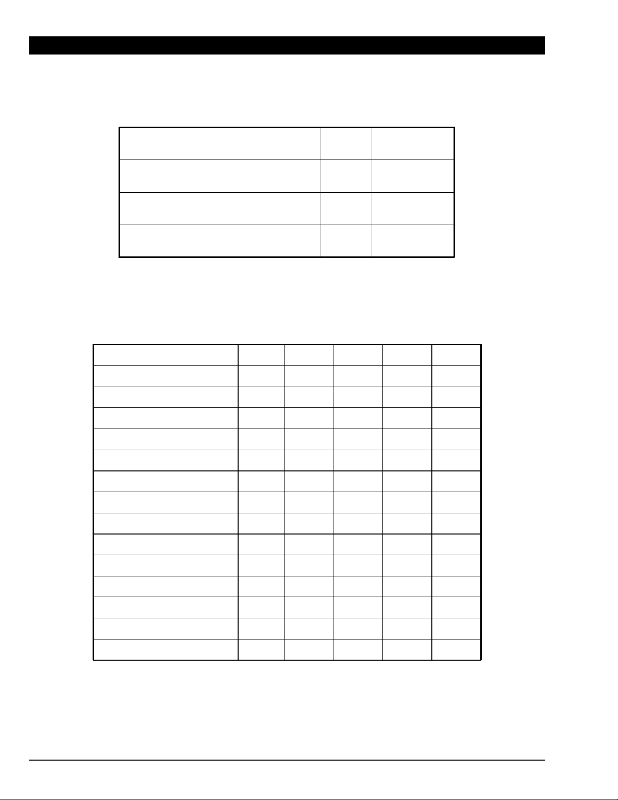
Ambient conditions
3. MAIN SPECIFICATIONS
Ambient operating temperature
Storage temperature
Maximum relative humidity
Maximum altitude
GROUP H (High spin soft mount washing machines)
MODEL EWH-25 EWH-30 EWH-40 EWH-60
Drum Volume
Maximum Load
Washer Dry Weight
Motor Power
Drain Diameter
Water Input Diameter
Optional Steam Input Diameter
Optional Steam Consumption
Static Floor Load
Maximum Dynamic Floor Load
Maximum Vertical Load
Dynamic Load Frequency
L
CuFt
Kg
Lb
Kg
Lb
kW
Hp
mm
Inc h
GHT &
BSPP
BSPP 1/2” 1/2” 1/2” 3/4”
Kg/h
Lb/h
KN
Lb
KN
Lb
KN
Lb
Hz 16.67 16.67 15.83 15.00
°C
°F
°C
°F
+5 / +41
+41 / + 106
+1 / +55
+34 / +131
%90
m
ft
94
3.3
10
25
212
467
0.75
1
76
3
3/4” 3/4” 3/4” 3/4”
7
15.5
2.08
467
0.75
169
2.83
636
130
4.6
13
30
254
560
1.1
1.5
76
3
8.5
17.7
2.49
560
1.05
236
3.54
796
1000
3280
181
6.4
18
40
348
767
2.2
3.0
76
3
12
26.5
3.41
767
1.40
315
4.81
1082
247
8.7
25
60
5002
1107
3.0
4.0
76
15
33.1
4.92
1107
1.75
393
6.67
1465
3
Maximum G Force
Maximum Noise Level
db <70 <70 <70 <70
450 450 450 350
4 113586-4
Page 5

GROUP R (Rapid spin rigid mount washing machines)
MODEL EWR-25 EWR-30 EWR-40 EWR-60
Drum Volume
Maximum Load
Washer Dry Weight
Motor Power
Drain Diameter
Water Input Diameter
Optional Steam Input Diameter
Optional Steam Consumption
Static Floor Load
Dynamic Floor Load
Maximum Vertical Load
Dynamic Load Frequency
L
CuFt
Kg
Lb
Kg
Lb
kW
Hp
mm
Inc h
GHT &
BSPP
BSPP 1/2” 1/2” 1/2” 3/4”
Kg/h
Lb/h
KN
Lb
KN
Lb
KN
Lb
Hz 12.67 12.67 12.00 11.50
100
3.5
10
25
212
467
0.7
51
76
3
3/4” 3/4” 3/4” 3/4”
7
15.5
2.08
467
5.0
1124
7.08
1592
130
4.6
13
30
241
531
1.1
1.5
76
3
8.5
17.7
2.36
531
6.0
1349
8.36
1880
181
6.4
18
40
282
622
1.5
2.0
76
3
12
26.5
2.77
622
8.0
1798
10.77
2420
247
8.7
404
891
2.2
3.0
33.1
3.96
891
10.0
2248
13.96
3139
25
60
76
3
15
Maximum G Force
Maximum Noise Level
db <70 <70 <70 <70
GROUP S (Standard spin rigid mount washing machines)
MODEL EWS-25 EWS-30 EWS-40 EWS-60 EWS-80
Drum Volume
Maximum Load
Washer Dry Weight
Motor Power
Drain Diameter
Water Input Diameter
Optional Steam Input Diameter
Optional Steam Consumption
Static Floor Load
Dynamic Floor Load
Maximum Vertical Load
Dynamic Load Frequency
L
CuFt
Kg
Lb
Kg
Lb
kW
Hp
mm
Inc h
GHT &
BSPP
BSPP 1/2” 1/2” 1/2” 3/4” 3/4”
Kg/h
Lb/h
KN
Lb
KN
Lb
KN
Lb
Hz 8.93 8.93 8.42 8.02 7.58
100
3.5
10
25
2044
50
0.75
1
76
3
3/4” 3/4” 3/4” 3/4” 3/4”
7
15.5
2.00
450
3.00
674
5.00
1124
200 200 200 200
130
4.6
13
30
235
518
1.1
1.5
76
3
8.5
17.7
2.31
518
4.00
899
6.31
1417
181
6.4
18
40
268
591
1.5
2.0
76
3
12
26.5
2.63
591
5.00
1124
7.63
1715
247
8.7
25
60
360
794
2.2
3.0
76
3
15
33.1
3.53
794
6.00
1349
9.53
2143
350
12.3
35
80
468
1032
3.0
4.0
76
3
18
39.7
4.59
1032
8.00
1798
12.59
2831
Maximum G Force
Maximum Noise Level
db <70 <70 <70 <70 <70
100 100 100 100 100
113586- 4 5
Page 6
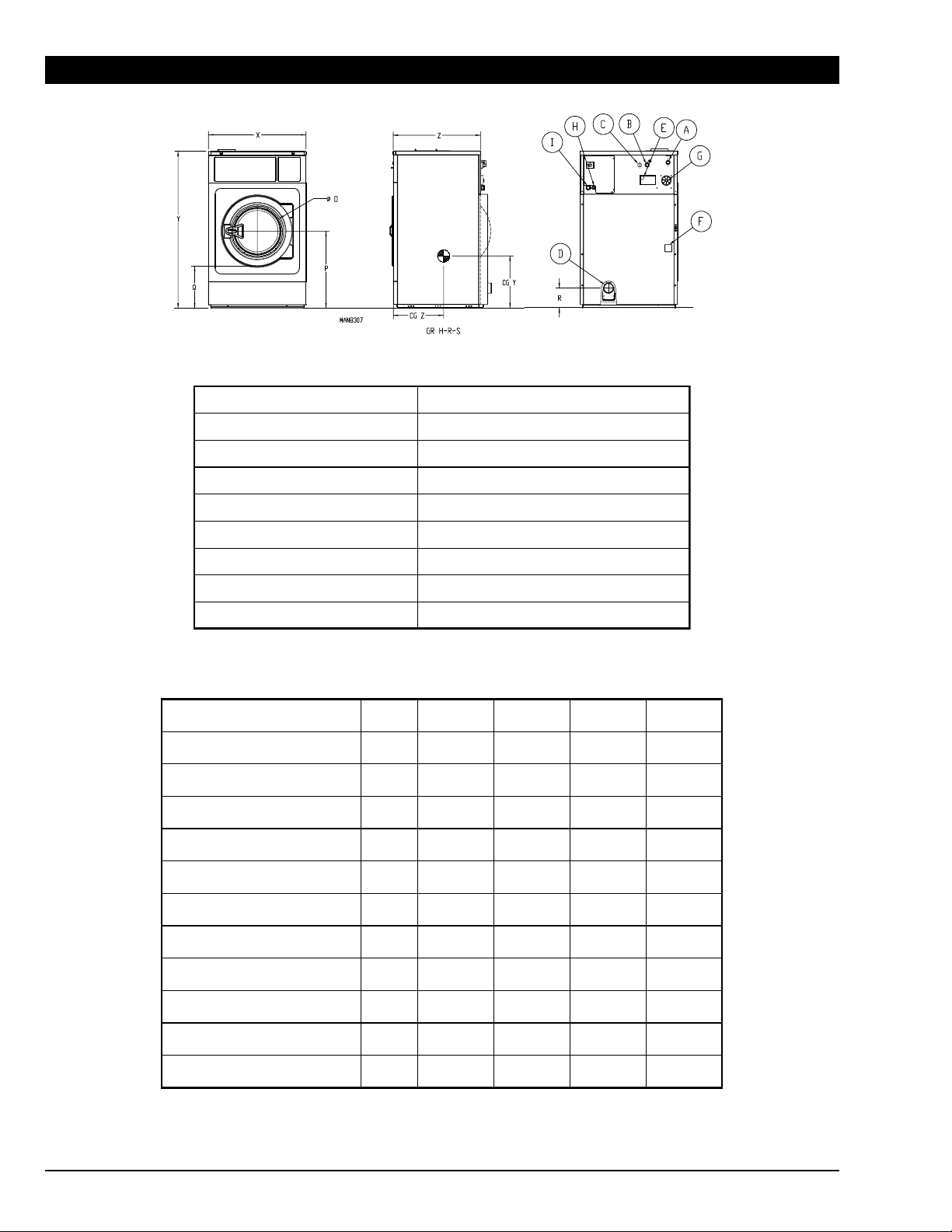
4. MAIN DIMENSIONS
A (Cold Water Inlet)
B (Hot Water Inlet)
C (Aux Water Inlet)
D (Drainage)
E (Tub Vent)
F (Steam Inlet-Optional)
G (Dispenser Inlets)
H (Ext. Dispenser Cable Inlets)
I (Main Power Cable Inlet)
GROUP H (High spin soft mount washing machines)
MODEL Unit EWH-25 EWH-30 EWH-40 EWH-60
M (Drum Diameter)
N (Drum Depth)
O (Entrance Diameter)
P (Drum Center Height)
Q (Under Door Height)
R (Drain Height)
X (Cabinet Width)
Y (Cabinet Height)
Z (Cabinet Depth)
CG Y (Center of Gravity)
CG Z (Center of Gravity)
mm
Inch
mm
Inch
mm
Inch
mm
Inch
mm
Inch
mm
Inch
mm
Inch
mm
Inch
mm
Inch
mm
Inch
mm
Inch
29-58 psi (2-4 bar)
29-58 psi (2-4 bar)
29-58 psi (2-4 bar)
29-58 psi (2-4 bar)
(7) 10 mm (3/8”) Hose, (1) 1/2” BSPP
532
21
425
16-3/4
290
11- 3/8
632
24-7/8
421
16-5/8
121
4-3/4
692
27-1/4
1162
45-3/4
791
31-1/8
424
16-3/4
577
22-3/4
620
24-3/8
430
16-7/8
373
14-5/8
689
27-1/8
432
17
126
5
788
31
1310
51-5/8
800
31-1/2
398
15-5/8
651
25-5/8
700
27-1/2
470
18-1/2
373
14-5/8
737
29
479
18-7/8
99
3-7/8
883
34-3/4
1410
55-1/2
845
33-1/4
464
18-1/4
702
27-5/8
770
30-3/8
530
20-7/8
373
14-5/8
853
33-5/8
595
23-3/8
130
5-1/8
979
38-1/2
1553
61-1/8
973
38-1/4
773
30-3/8
503
19-3/4
6 113586-4
Page 7
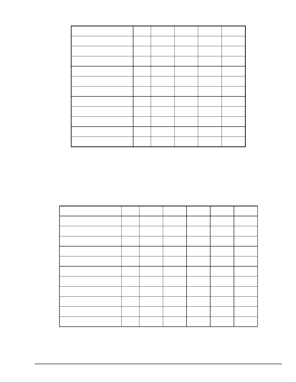
GROUP R (Rapid spin rigid mount washing machines)
MODEL Unit EWR-25 EWR-30 EWR-40 EWR-60
M (Drum Diameter)
N (Drum Depth)
O (Entrance Diameter)
P (Drum Center Height)
Q (Under Door Height)
R (Drain Height)
X (Cabinet Width)
Y (Cabinet Height)
Z (Cabinet Depth)
CG Y (Center of Gravity)
CG Z (Center of Gravity)
mm
Inc h
mm
Inc h
mm
Inc h
mm
Inc h
mm
Inc h
mm
Inc h
mm
Inc h
mm
Inc h
mm
Inc h
mm
Inc h
mm
Inc h
620
24-3/8
330
13
373
14-5/8
568
22-3/8
310
12-1/4
145
5-3/4
719
28-1/4
1157
45-5/8
645
25-3/8
383
15-1/8
511
20-1/8
620
24-3/8
430
16-7/8
373
14-5/8
568
22-3/8
310
12-1/4
144
5-5/8
719
28-1/4
1157
45-5/8
791
31-1/8
484
19
524
20-5/8
700
27-1/2
470
18-1/2
373
14-5/8
653
25-3/4
395
15-5/8
112
4-3/8
788
31
1307
51-1/2
800
31-1/2
479
18-7/8
546
21-1/2
770
30-3/8
530
20-7/8
373
14-5/8
691
27-1/4
433
17
150
5-7/8
884
34-3/4
1319
51-7/8
965
38
543
21-3/8
591
23-1/4
GROUP S (Standard spin rigid mount washing machines)
MODEL Unit EWS-25 EWS-30 EWS-40 EWS-60 EWS-80
M (Drum Diameter)
N (Drum Depth)
O (Entrance Diameter)
P (Drum Center Height)
Q (Under Door Height)
R (Drain Height)
X (Cabinet Width)
Y (Ca bi net Height)
Z (Cabinet Depth)
CG Y (Center of Gravity Height)
CG Z (Center of Gravity Depth)
mm
Inc h
mm
Inc h
mm
Inc h
mm
Inc h
mm
Inc h
mm
Inc h
mm
Inc h
mm
Inc h
mm
Inc h
mm
Inc h
mm
Inc h
620
24-3/8
330
13
373
14-5/8
568
22-3/8
310
12-1/4
145
5-3/4
719
28-1/4
1157
45-5/8
645
25-3/8
383
15-1/8
511
20-1/8
620
24-3/8
430
16-7/8
373
14-5/8
568
22-3/8
310
12-1/4
144
5-5/8
719
28-1/4
1157
45-5/8
791
31-1/8
484
19
524
20-5/8
700
27-1/2
470
18-1/2
373
14-5/8
653
25-3/4
395
15-5/8
112
4-3/8
788
31
1307
51-1/2
800
31-1/2
479
18-7/8
546
21-1/2
770
30-3/8
530
20-7/8
373
14-5/8
677
26-5/8
419
16-1/2
148
5-7/8
884
34-3/4
1307
51-1/2
965
38
591
23-1/4
543
21-3/8
860
33-7/8
602
23-7/8
560
22
733
28-7/8
373
14-5/8
149
5-7/8
979
38-1/2
1411
55-1/2
1057
41-5/8
635
25
682
26-7/8
113586- 4 7
Page 8

5. IMPORTANT INSTRUCTIONS REGARDING SAFETY AND USE
WARNING: To reduce the risk of electrical shocks or
injury when using the appliance, basic precautions
should be observed, including the following:
1- READ all the instructions prior to using the appliance
and KEEP THEM in an easily accessible place for
reference in the event of doubt.
2- This appliance must be installed by an Official or
authorized Technical Assistance Service. The
installation, incorrect adjustment, inappropriate
maintenance or use of the appliance may cause
material damages and injuries. Before
commissioning the appliance, carefully read the
instructions contained in this manual. These contain
important information about the installation of the
appliance
3- The incorrect installation, inappropriate servicing,
poor maintenance and/or cleaning and
modifications to the appliance may cause damage
to both the appliance and the users.
4- Failure to comply with the given procedures will
result in the loss of cover under guarantee.
5- Switch off the appliance in the event of breakdown
or faulty operation.
6- Do not wash clothes which have been previously
treated, washed, soaked or stained with gasoline,
dry cleaning solvents, or other inflammable or
explosive substances, as these give off vapors,
which may catch fire or explode.
7- Do not add petrol, dry cleaning solvents or other
inflammable substances to the washing water.
These substances give off vapours which could
catch fire or explode.
8- In some conditions, hydrogen gas may be produced
in a hot water system which has not been used for
more than two weeks. HYDROGEN GAS IS
EXPLOSIVE. If the hot water system has not been
used for a while, before using the washing machine
turn on all the hot water taps and let the water run
for a few minutes. This will release any accumulated
hydrogen gas. As the gas is inflammable, do not
smoke or use naked flames during this operation.
9- Do NOT allow children to play in or on the appliance.
Children should be strictly supervised when in the
vicinity of a machine which is operating.
10- Remove the door from the appliance before disposal
or before leaving it out of service.
11- DO NOT TRY TO OPEN THE DOOR if the drum is
moving.
12- Do NOT install or store the appliance in the open.
13- Do NOT try to force the controls.
14- Do not repair or replace parts of the appliance or
carry out any servicing unless recommended to do
so in the User Instruction Manual. Make sure that
you fully understand the instructions and have the
necessary skills to carry out the operations
described.
15- Do NOT remove any safety device or modify any
components in the washing machine. DO NO
INSTALL components not belonging to the machine
in the appliance.
16- Failure to comply with any of the instructions given
in the Instruction Manual may result in personal
injury to the user. It is no possible to provide for all
possible situations and contingencies with warnings
about risk and hazards. Therefore, any person
involved in the transportation, installation, use or
maintenance of the machine should always employ
common sense, caution and care.
17- Do NOT use the machine unless all the covers and
guards are correctly fitted and secured.
18- The distributor (vendor) MUST correctly instruct the
user during commissioning.
19- Pour the correct doses of detergent, fabric softener
and bleach into the dispenser drawer, as indicated
by the manufacturer. Heed tips concerning the
treatment of different materials given by the
manufacturers.
20- Remove any traces of detergent or liquids from the
dispenser drawer everyday. Never use powdered
or abrasive detergents for cleaning; use only water
and soap.
21- Clean the water inlet filters and the external
dispenser conducts once a month.
8 113586-4
Page 9

22- Never clean the exterior with a pressure washer;
functional parts of the machine could be damaged.
23- If the washing machine is to be idle for long periods,
apply a coat of Vaseline oil to all its stainless steel
surfaces.
WARNING! Repairs or work carried out by personnel
not belonging to the authorised Technical Service
will void the warranty.
CAUTION! Fire protection regulations must be strictly
observed.
24- An annual general service is recommended.
KEEP THESE INSTRUCTIONS IN A SAFE PLACE
WARNING! Before starting to connect the appliance,
check that the installation values match those given
on the appliance specification plate.
113586- 4 9
Page 10

6. STANDARDS
All models comply to standard EN ISO 10472 concerning the safety requirements for industrial laundry machinery.
2006/42/EC Machinery Safety Directive
2006/95/EC Low Voltage
2004/108/EC Electromagnetic Compatibility Directive
UL Standard for Electric Clothes Washing Machines and Extractors; UL 2157 and CSA C22.2 No. 169
For models with a drum capacity of less than 120 dm
Standards EN 60335-1 and EN 60335-2-7 concerning Electrical appliances.
Standards EN 55014, EN 61000-3-2 and EN 61000-3-3 on Electromagnetic compatibility.
For models with a larger capacity:
Standard EN 60204-1 concerning Electrical appliances.
Standards EN 61000-6-1, EN 61000-6-3 y EN 61000-3-1 on Electromagnetic compatibility.
3
(4.24 cu.ft):
7. TRANSPORT
When transporting the appliance, the following should be observed:
o
Current regulations and laws
o
Regulations concerning occupational risk prevention
o
Regulations concerning safety during transport
Check the delivery is in good condition prior to receipt.
8. CHARACTERISTICS OF THE PLACE OF INSTALLATION
In some locations, an omnipolar switch must be installed between the appliance and the mains electricity supply with
a minimum distance of 3 mm for each pole between contacts. Check your local regulations.
The washing machine must be firmly secured on the floor, which will support its weight and the dynamic force
generated while spinning.
The washing machine must be correctly leveled leaving spaces to make maintenance easier, 0.5 m on the side and
1 m at the rear.
WARNING! The stopcocks should be close to the appliance in an easily accessible location.
9. HANDLING
When handling the appliance, the following should be observed:
o
Current regulations and laws
o
Regulations concerning occupational risk prevention
-
Safety clothing and gloves must be worn for protection against cuts and knocks and safety shoes should
be used to prevent against injury as a result of falling components.
-
When handling and moving the appliance, appropriate tools and resources must be used.
-
Any work to the interior of the appliance must be carried out by qualified and skilled personnel.
CAUTION! Inappropriate handling of the appliance may result in damage or injury.
10 113586-4
Page 11

10. INSTALLATION (ALL MODELS)
10.1 Water Connection
If only cold water is available, connect as shown in figure 3. Where hot water is available, connect as shown in figure
4. If, in addition, decalcified water is available, connect as shown in figure 5. NOTE: not all washer models have a
third decalcified water valve.
A. F.
A. C.
Fig. 3
Connections on the washer are 3/4” GHT
A. F.
A. C.
Fig. 4
Fig. 5
A. D.
A. F.
A. C.
For 3/4” BSPP connection, remove the brass GHT adaptor.
A=Stopcock B=Filter C=Hose A.C.=Hot water A.F.=Cold water A.D.=Decalcified water
Water Pressure Range: 29 - 58 PSI / 2 - 4 Bar.
VERY IMPORTANT: Bleed water circuit prior to installation and fitting filters.
10.2 Steam Connection
If your washer is fitted with optional steam heat, the water in the tub can be heated by direct steam injection. The connection
diagram is shown in the figure. See the main specifications section for the connection size on your model.
Warning!
Failure to fit the filters on the water
and steam inputs will void the warranty
on the corresponding components
Steam Pressure Range: 29 - 58 PSI / 2 - 4 Bar.
VERY IMPORTANT: Bleed steam circuit prior to installation and fitting filters
After steam has been introduced into the machine for the first time, it is advisable for the steam hose nuts to be retightened.
10.3 Drainage
Fix the drainage bend pipe as shown in the figure. Be sure to check and follow any local plumbing regulations.
A=Drainage pipe bend
B=Clamp
The drain flow rate for all models is up to 47 GPM (178 LPM). Be sure that the system
is designed to handle that flow rate. If multiple washers are installed in line, be sure the
system is designed to handle the combined flow from all the washers.
113586- 4 11
Page 12

10.4 Electrical Connection
GROUP H (High Speed Soft Mount Washing Machines)
Standard or With
Optional Steam
Heating
EWH-25 3.5 15 14 3.5 15 14
EWH-30 6.8 15 14 6.8 15 14
EWH-40 10.1 15 12 10.1 15 12
EWH-60 13.7 20 12 7.9 15 14
Operating
Amperage
230V-1~ 230V-3~
FUSE
(A)
AWG
Operating
Amperage
FUSE
(A)
AWG
GROUP R-S (Rapid and Standard Speed Rigid Mount Washing Machines)
Standard or With
Optional Steam
Heating
EWS-25/EWR-25 3.5 15 14 3.5 15 14
EWS-30/EWR-30 5.0 15 14 5.0 15 14
EWS-40/EWR-40 6.8 15 14 6.8 15 14
EWS-60/EWR-60 10.1 15 12 10.1 15 12
EWS-80 13.7 20 12 7.9 15 14
Operating
Amperage
230V-1~ 230V-3~
FUSE
(A)
AWG
Operating
Amperage
FUSE
(A)
AWG
Connection to Washer
These washers were designed for direct wiring into the power supply. The washer must be electrically grounded in
accordance with all local codes or, in the absence of local codes, with the National Electrical Code, ANSI/NFPA 70,
latest edition, or Canadian Electrical Code, CSA C22.1.
Direct Wire Installation:
Power supply cable must match power supply (3-wire or 4-wire) and be:
■ Flexible armored cable or nonmetallic sheathed copper cable (with grounding wire), in a flexible metallic conduit.
Flexible conduits must be used to avoid conductor breakage due to vibration. All current-carrying wires must be
insulated.
■ Copper wire of appropriate gauge for amperage requirement (see “Manufacturer’s Recommended Minimal Conductor
Section”). Stranded wire is recommended. Do not use aluminum wire.
WARNING: Risk of electrical shock
Connection is made directly to the disconnect switch on the back of the washer. To access the connections remove
the rear electric box cover. To access the heads of the connection screws, the red handle and yellow cover have to
be removed from the disconnect switch. The handle is held in place with a wedge on the switch shaft that is driven by
a Phillips head screw in the center of the handle. Loosen the screw and push in on it to release the wedge. Pull off
the handle. Note the orientation of the handle and the yellow parts so that they can be replaced in the same locations.
Check the rating plate on the washer. Make sure
that the supply phase and voltage match the rating
of the washer.
Some locations require an autonomous power
switch (I) at the current input, with a minimum of 3
mm between contacts. Fit a 300mA, type A,
immediate response differential protection. Check
your local regulations.
Insert the power cord through the large strain relief.
Connect the wiring per the correct illustration.
12 113586-4
Page 13

Multiple Single-Phase Machines in Line
When installing multiple single-phase washers into an existing 3-phase power supply, alternating the phases used as
the hot leg is recommended to evenly distribute power on the system. See illustration.
INSTRUCTIONS FOR CONNECTING THE EARTH
This appliance must be connected to an equipment grounding conductor that must run with the circuit conductors
and connected to the green and yellow terminal block inside the rear electric panel.
Connect the terminal strip and check that the connections correspond to the operating voltage. Fit a 300mA, type A,
immediate response differential protection.
The machine must be connected to earth. See the illustration on the previous page.
Equipotential Bonding:
In addition to the equipment-grounding conductor discussed earlier that runs with the circuit conductor’s and is
connected to the equipment grounding terminal, all washers or appliances in the vicinity must be permanently
interconnected with a grounded connector.
The external connection points marked on the back of the washer serve for this purpose. See illustration below.
The cross-sectional area of the conductor must be at least electrically equivalent to the cross-sectional area of the
copper conductor used to power the washer.
1.
Protective grounding structure
2.
External protective conductor connection point
3.
Protective
4.
Grounding identification
113586- 4 13
interconnecting
conductor
Page 14

10.5 Auxiliary Connections
See the figure below of the Auxiliary connections label found just outside the rear electric box on the washer. The
figure shows the locations of the connections described below.
a) The max current draw allowed on each connection is 0.5 Amps.
b) Connections 1 thru 4 are the same signal used to send water to the indicated area of the washer’s soap dispenser.
c) Connections 9-10, 11-12, 13-14 are shown on the wiring diagram. A copy of the diagram can be found in a pouch
on the back side of the hinged control door.
1: 230 V electrical signal. For dispenser 1 (prewash)
2: 230 V electrical signal. For dispenser 2 (wash)
3: 230 V electrical signal. For dispenser 3 (bleach)
4: 230 V electrical signal. For dispenser 4 (softener)
5: 230 V electrical signal. For dispenser 5 (ONLY ON MP MODELS)
6: 230 V electrical signal. For dispenser 6 (ONLY ON MP MODELS)
7: 230 V electrical signal. For dispenser 7 (ONLY ON MP MODELS)
R: (has no label) is located between terminal 7 and 9-10. This connection is a constant 230v auxiliary power source,
and has power as long as power is connected to the washer.
9-10: Active machine signal is a NO contact on the RG1 relay that powers the VFD. Contact closes when a wash
cycle is running.
11-12: This is the coin pulse signal from a central or card reader pay system.
13-14: Is a connection for an external e-stop. Remove the orange jumper and install the e-stop across this connection.
10.6 Dispenser Inlet Connections
See the figure at the top of page 6 for the location of the dispenser inlets.
There are (7) 3/8” (10mm) hose connections in a circular pattern around a central 1/2” BSPP threaded connection.
The hose connections are plugged. Before connecting a hose, drill the plug out using a 5/16” (8mm) diameter drill bit.
The threaded connection is open and has a brass cap on it. Remove the cap to connect to the port.
Port has 1/2” BSPP (G-1/2) straight thread. Sealing is achieved by a washer on the face of the port. For low pressure
applications where BSP fittings are unavailable, 1/2” NPT fittings with a thread sealant can be used.
14 113586-4
Page 15

11. INSTALLATION OF GROUPS H-R-S
11.1 Soft Washer Mounting Dimensions
MODELUnitW1W2W3W4W5W6W7W8W9
EWH-25
EWH-30
EWH-40
EWH-60
Inc h
mm
Inc h
mm
Inc h
mm
Inc h
mm
18-1/8
460
21-7/8
556
21-3/8
543
29-7/8
760
4-5/8
116
4-5/8
116
6-3/4
170
4-1/4
110
1-7/8
49
2
51
1-7/8
48
1-3/4
44
20-7/8
530
22-1/4
566
24-7/8
633
31-1/2
800
3-1/4
81
4-3/8
111
4-7/8
125
3-1/2
90
3-3/4
95
4-1/4
108
4-5/8
119
4-1/2
114
21-1/2
546
20-3/4
526
21-3/8
544
25-3/8
644
**
31-1/8
791
31-1/2
800
33-1/4
845
38-1/4
973
27-1/4
692
31
788
34-3/4
883
38-1/2
979
(*) Dimensions W8 and W9 refer to the washer cabinet only. They do not include any protrusions front of back.
Allow for a minimum 3/4” (19mm) side gap between adjacent washers or other machinery.
To keep the washer from moving, it’s recommended that it be lagged to the floor with 3/8” (10mm) dia screws in the
locations shown.
113586- 4 15
Page 16

11.2 Rigid Washer Mounting Dimensions
GROUP R (Fast spin rigid washing machines)
MODELUnitW1W2W3W4W5W6W7W8
EWR-25
EWR-30
EWR-40
EWR-60
Inc h
mm
Inc h
mm
Inc h
mm
Inc h
mm
19-11/16
500
19-11/16
500
22-1/16
560
24-7/16
620
11-7/8
301
12
305
14-1/2
368
15-1/4
387
5-7/8
149
9-1/8
232
9-1/8
232
11-11/16
300
4-5/16
110
4-5/16
110
4-1/2
114
5-3/16
132
4-3/4
121
6-1/4
158
4-13/16
122
7-7/8
200
2-7/8
73
3-11/16
93
3-1/8
77
3
76
28-1/4
719
28-1/4
719
31
788
34-3/4
884
GROUP S (Standard spin rigid washing machines)
MODELUnitW1W2W3W4W5W6W7W8
EWS-25
EWS-30
EWS-40
EWS-60
EWS-80
Inc h
mm
Inc h
mm
Inc h
mm
Inc h
mm
Inc h
mm
19-11/16
500
19-11/16
500
22-1/16
560
24-7/16
620
27-9/16
700
11-7 /8
301
12
305
14-1/2
368
15-1/4
387
19-5/16
490
5-7/8
149
9-1/8
232
9-1/8
232
11-11 /16
300
11-13/16
300
4-5/16
110
4-5/16
110
4-1/2
114
5-3/16
132
5-1/2
139
4-3/4
121
6-1/4
158
4-13/16
122
5-13/16
147
5-1/2
140
2-7/8
73
3-11/16
93
3-1/8
77
5-1/16
129
5
127
28-1/4
719
28-1/4
719
31
788
34-3/4
884
38-1/2
979
25-3/8
644
31
788
31-1/2
799
38
963
25-3/8
644
31
788
31-1/2
799
38
963
41-5/8
1057
(*) Dimensions W7 and W8 refer to the washer cabinet only. They do not include any protrusions front of back.
Allow for a minimum 3/4” (19mm) side gap between adjacent washers or other machinery.
16 113586-4
Page 17

Forces transmitted by the washing machine
11.3 Group (H) Washers
EWH-25 EWH-30 EWH-40 EWH-60
Static floor load (Kn - lb) 2.08 - 467 2.49 - 560 3.41 - 767 4.92 - 1107
Dinamic floor load (Kn - lb) 0.75 - 169 1.05 - 236 1.40 - 315 1.75 - 393
Maximum vertical load (Kn - lb) 2.83 - 636 3.54 - 796 4.81 - 1082 6.67 - 1465
Dynamic load frequency (Hz) 16.67 16.67 15.83 15.00
G factor 450 450 450 350
Group (R) Washers
EWR-25 EWR-30 EWR-40 EWR-60
Static floor load (Kn - lb) 2.08 - 467 2.36 - 531 2.77 - 622 3.96 - 891
Dinamic floor load (Kn - lb) 5.0 - 1124 6.0 - 1349 8.0 - 1798 10.0 - 2248
Maximum vertical load (Kn - lb) 7.08 - 1592 8.36 - 1880 10.77 - 2420 13.96 - 3139
Dynamic load frequency (Hz) 12.67 12.67 12.00 11.50
G factor 200 200 200 200
Min. Anchorage Points* 4444
Min. Concrete Thk. (mm - in) 150 - 6 150 - 6 200 - 8 200 - 8
Group (S) Washers
EWS-25 EWS-30 EWS-40 EWS-60 EWS-80
Static floor load (Kn - lb) 2.00 - 450 2.31 - 518 2.63 - 591 3.53 - 794 4.59 - 1032
Dinamic floor load (Kn - lb) 3.00 - 674 4.00 - 899 5.00 - 1124 6.00 - 1349 8.00 - 1798
Maximum vertical load (Kn - lb) 5.00 - 1124 6.31 - 1417 7.63 - 1715 9.53 - 2143 12.59 - 2831
Dynamic load frequency (Hz) 8.93 8.93 8.42 8.02 7.58
G factor 100 100 100 100 100
Min. Anchorage Points* 44444
Min. Concrete Thk. (mm - in)** 100 - 4 100 - 4 150 - 6 150 - 6 200 - 8
* The (2) anchorage points at the front must be used, (2) of the (4) anchorage points at the back must be used.
The (2) furthest to the back are preferred.
** Increasing the number of anchor points does not reduce the required concrete thickness.
WARNING! Soft and rigid mount washing machines must not be installed on non-foundation floors without
authorization from a technician familiar with the structure and resistance of the building.
Please check the weight of the machine plus the dynamic forces generated during spinning. The
manufacturer does not accept responsibility for any damage due to vibration in this type of installation.
WARNING! RIGID MACHINES MUST BE ANCHORED TO THE FLOOR. Correct construction of the anchorage
to the floor is essential to ensure the correct working of the appliance and to prevent serious damage to
the structure of the machine.
113586- 4 17
Page 18

11.4 Using a Steel Base
75 mm
F
G
F + 120 mm
Installation on a Steel Base
The steel base structure must be able to withstand the static and dynamic loads of the washer floor (see “Transmitted
Forces” chart on the previous page). The base must also allow the washer to be seated in a perfectly level manner.
Bases specifically designed for this washer are available from ADC.
11.5 Using an Elevated Concrete Pad
Installation on an Elevated Concrete Pad
Use this method if the existing floor is thinner than the
minimum in the mounting chart, or if the washer is to be
positioned above the existing floor level. The minimum height
of the elevated pad will be 4”–8” (100–200 mm) depending
on the washer model (see “Dimensions” illustration to the
right).
1. Break up and remove the existing floor down to a depth
of approx. 3” (75 mm) (see “Floor Removal” illustration
below). The hole should flare out at the bottom so that
it is about 5” (120 mm) wider at the bottom than the top.
Dimension F = W1 + 400mm, G = W2+W3+400mm
(see the “Rigid Washer Mounting Dimensions” chart).
2. Wet the complete hole and spread over with cement.
3. To increase the load-bearing capacity and reduce
possible concrete deformations, we recommend
inserting an armature into the base of the pad. For
adequate connection of the new pad with the existing
floor, insert one or more reinforcing bars.
NOTE: When inserting the reinforcing bar(s), take into
consideration the locations (and space requirements) for
drilling holes. These holes will be used for the chemical or
expansion anchor bolts.
NOTE: If casting anchor bolts into the pad, be sure to set
the bolts so that the front face of the washer is flush with the
face of the pad.
4. Pour concrete into the prepared base. Level the surface
carefully into a horizontal plane.
5. Let the concrete harden for at least two days before
installation of the washer. Wait one week before
operating the washer with a full load.
4” - 8”
(100 - 200 mm)
Dimensions
➤
➤
➤
Floor Removal
75 mm
G +120 mm
➤
➤
➤
(50 mm)
➤
➤
G+120mm
2”
➤
18 113586-4
Page 19

Installation of the rigid washer-extractor without anchorage base
11.5.1 Using Expansion Bolts
Before anchoring the machine to the floor, make sure that its minimum resistance is equal or higher than 3500 psi
(25N/mm2).
First mark the locations of the mounting holes using the dimensions specified in the “Rigid Washing Machines” chart.
Next drill the mounting holes. Follow the manufacturing installation instructions, but the holes must be at least 4
inches (100mm) deep. The holes must not go all the way through the floor. Clean the holes with compressed air.
Place the washer-extractor in position over the holes, then insert the expansion bolts in the holes. Be sure to use
5/8-11 (M16) expansion bolts, and that they protrude above the surface by 2 inches (50mm). Once in place, tighten
the bolts until the machine is securely fastened.
11.5.2 Using J-bolts
Before anchoring the machine to the floor, make sure that its minimum resistance is equal or higher than 3500 psi
(25N/mm2).
First mark the locations of the mounting holes using the dimensions specified in the “Rigid Washing Machines” chart.
Next make holes to a depth, at minimum, equal to 4 inch (100mm). Make the holes big enough to insert the J-bolt and
clean using compressed air. Insert the J-bolt s in the holes and secure using a suitable anchoring compound, ensuring
that the bolt protrudes above the surface by 2-1/2 inches (60mm). Be sure to use 5/8-11 (M16) J-bolts.
Place the washer-extractor in position above the bolts, and gradually tighten the nuts one after another until the
machine is securely fastened.
Check the condition of the J-bolts one week after installation.
113586-4 19
Page 20

12. INSTALLATION OF SELF-SERVICE WASHING MACHINES (GROUP H-R-S)
Card kit
Coin kit
Washers are delivered in the configuration ordered, and are ready for installation. Self service options are listed
below. The washer can be converted to anyone of these option. Conversion kits are available from your dealer.
12.1 Central Pay
Self-service machines with this configuration are ready for connection to a pay center. The pay center receives an
electrical signal from the washing machine informing of its availability and, at the same time, the washing machine
receives the signal that the correct money has been inserted and the programme may be run. The price and currency
settings are external to the washing machine and can therefore not be programmed. Please see the user manual for
details on the use of this self-service configuration.
12.2 Card Reader
The card reader operates in almost the same way as the central pay machine, prices and currency are programmed
on the card reader. Please see the user manual for details on the use of this self-service configuration.
12.3 Coin
On coin washers, the currency and price settings for each wash cycle are internal to the washer. Please see the user
manual for instructions on the use of this self-service configuration.
¡WARNING! The installation of the different self-service kits involves working with electrical components.
Switch off the machine before any work.
Work carried out by personnel not belonging to the authorised Technical Service will result in the loss of
warranty coverage.
20 113586-4
Page 21

13. WASHING MACHINE INSTALLATION AND MAINTENANCE
WASHING MACHINE INSTALLATION CHECKLIST
MODEL 25,30,40,60,80
Unpack removing the bag and corner pieces
Check that the specification plates correspond with the order
POSITIONING
INSTALLATION
Ensure that the floor withstands the weight and maximum force transmitted by the machine
Fit out the machine location so that it is levelled and the necessary distances are observed for maintenance
It is advisable that the floor is not slippery
Remove the transport anchors
Fixing all (Group H) washing machines to the floor is recommended
Fixing all (Group R&S) washing machines to the floor is mandatory
Flush water circuits prior to making the connectio ns
Install water hoses (a filter is required in the cold water inlet)
Ensure that the water pressure at the machine inlet is from 2 to 4 bars
STEAM machines: - installing Teflon joints on both ends of the hose is compulsory
- installing a filter in the steam electrovalve inlet is compulsory
- always open the steam cock gradually and not suddenly
- retighten the steam hose nuts
Installing a 300 mA differential switch between the wiring and the mains is recommended
Connect the mains supply. Compare mains voltage and machine voltage (observe specification plate)
Before turning the line breaker on measure voltage between phases and phase-neutral
It is advisable for the voltage between neutral and earth be equal to zero
Connect drainage pipe. Important: ensure the correct inclination for full water disposal
GENERAL
DAILY
WEEKLY
THREE-MONTHLY
WASHING MACHINE PREVENTIVE MAINTENANCE
Leaving the door open when the washing machine is not running is recommended
Put in the correct load (complete) and select the appropriate programme
At the end of the shift, clean the door seal with a damp cloth and turn the machine off
Clean the water inlet filters
Clean the detergent tray compartments so that there are no blockages
Clean the outside of the machine with a damp cloth
Clean converter ventilation filter and motor fan grille
Check belt tension
113586- 4 21
Page 22

Part No. 113586 4 - 02/01/17
 Loading...