

Page 1
HiGain
HiGain
EDU-409
HiGain
DOUBLER
L
STATUS
USER MANUAL
EDU-409 List 1 Doubler Unit
Product Catalog: 150-409-115-05
Page 2

150-409-115-05, Issue 5
Revision History of This Manual
To order copies of this document, use document catalog number
150-409-115-05.
Issue Release Date Revisions Made
01 August 14, 1998 Initial release
02 August 24, 1998 Modify Tables 1 and 2
03 March 26, 1999 Update Technical Specifications
04 January 26, 2000 Change practice title
05 March 1, 2002 ADC rebranding of document; no technical changes
Copyright
January 26, 2000
© 2000 ADC DSL Systems, Inc. All rights reserved.
Trademark Information
ADC is a registered trademark of ADC Telecommunications, Inc. HiGain is a
registered trademark of ADC DSL Systems, Inc. No right, license, or interest to such
trademarks is granted hereunder, and you agree that no such right, license, or interest
shall be asserted by you with respect to such trademark.
Other product names mentioned in this practice are used for identification purposes
only and may be trademarks or registered trademarks of their respective companies.
Disclaimer of Liability
Information contained in this document is company private to ADC DSL Systems, Inc.,
and shall not be modified, used, copied, reproduced or disclosed in whole or in part
without the written consent of ADC.
Contents herein are current as of the date of publication. ADC reserves the right to
change the contents without prior notice. In no event shall ADC be liable for any
damages resulting from loss of data, loss of use, or loss of profits, and ADC further
disclaims any and all liability for indirect, incidental, special, consequential or other
similar damages. This disclaimer of liability applies to all products, publications and
services during and after the warranty period.
ii January 26, 2000 EDU-409 List 1
Page 3
150-409-115-05, Issue 5 Using This Manual
USING THIS MANUAL
The following conventions are used in this manual:
• Monospace type indicates screen text.
• Keys you press are indicated by small icons such as or . Key
Y ENTER
combinations to be pressed simultaneously are indicated with a plus sign
as follows: + .
CTRL ESC
• Items you select are in bold.
Three types of messages, identified by icons, appear in text.
Notes contain information about special circumstances.
Cautions indicate the possibility of personal injury or
equipment damage.
The Electrostatic Discharge (ESD) symbol indicates that a
device or assembly is susceptible to damage from electrostatic
discharge.
For a list of abbreviations used in this document, refer to “Glossary” on
page 25.
UNPACK AND INSPECT YOUR SHIPMENT
Upon receipt of the equipment:
• Unpack each container and inspect the contents for signs of damage. If
the equipment has been damaged in transit, immediately report the extent
of damage to the transportation company and to ADC DSL Systems, Inc.
Order replacement equipment, if necessary.
• Check the packing list to ensure complete and accurate shipment of each
listed item. If the shipment is short or irregular, contact ADC DSL
Systems, Inc. as described in “Product Support” on page 23. If you must
store the equipment for a prolonged period, store the equipment in its
original container.
EDU-409 List 1 January 26, 2000 iii
Page 4

Unpack and Inspect Your Shipment 150-409-115-05, Issue 5
iv January 26, 2000 EDU-409 List 1
Page 5

150-409-115-05, Issue 5 Table of Contents
TABLE OF CONTENTS
Overview _______________________________________________ 1
Features.................................................................................... 1
Applications............................................................................. 2
Product Description ______________________________________ 5
Cover........................................................................................ 5
Front Panel............................................................................... 6
Installation _____________________________________________ 7
Compatibility ........................................................................... 7
Installing the EDU-409 List 1..................................................7
Alarms _________________________________________________ 9
Loopback Operation ____________________________________ 10
Functional Description___________________________________ 11
Doubler Enclosure Capacities with Full Solar Load.............. 12
Alternative Doubler Enclosure Capacities............................. 16
Micro Doubler Capacity Deployment Rules.......................... 18
Ground Faults__________________________________________ 19
Ground Fault Detection.......................................................... 19
Ground Fault Isolation........................................................... 20
Technical Specifications__________________________________ 21
Product Support________________________________________ 23
Abbreviations __________________________________________ 24
Glossary_______________________________________________ 25
Certification and Warranty__________________Inside Back Cover
EDU-409 List 1 January 26, 2000 v
Page 6

List of Figures 150-409-115-05, Issue 5
LIST OF FIGURES
1. EDU-409 List 1 Front Panel..................................................................6
2. Installing the EDU-409 List 1 in a Remote Enclosure..........................8
3. HiGain Loopbacks...............................................................................10
4. Doubler Block Diagram ......................................................................11
5. AT&T 819 Enclosure..........................................................................17
LIST OF TABLES
1. HDSL Signal Cable Loss ......................................................................2
2. EDU-409 List 1 Circuit Ranges ............................................................3
3. Front Panel Components and Labels.....................................................6
4. Front Panel Status Indicator ..................................................................9
5. Indoor Enclosure Capacities................................................................13
6. Outdoor Enclosure Capacities with Full Solar Load...........................14
7. Fault Isolation Guide...........................................................................20
vi January 26, 2000 EDU-409 List 1
Page 7

150-409-115-05, Issue 5 Overview
OVERVIEW
The HiGain® EDU-409 List 1 List 1 is a low-power doubler unit that extends
the range of a HiGain repeaterless G.703 transmission system. The doubler
units are installed between any doubler-compatible HiGain E1 Line Unit
(ELU) and HiGain E1 Doubler (EDU) or HiGain E1 Remote Unit (ERU).
They allow 2.048 Mbps transmission over twice the normal High Capacity
Digital Service (HCDS) range.
Adding a doubler can double the HCDS range to approximately 7.32 km
(24,000 feet) of 0.51-mm wire or 5.49 km (18,000 feet) of 0.4-mm wire loops.
Two doublers can triple the HCDS range to 10.97 km (36,000 feet) of
0.51-mm wire or to 8.22 km (27,000 feet) of 0.4-mm wire loops. Three
doublers extend the 0.51-mm wire range to 14.6 km (48,000 feet).
FEATURES
The EDU-409 List 1 includes:
• Occupation of one standard 239 T1 mechanics slot
• Power by any doubler-compatible HiGain line unit
• Front-panel status display LED
• Lightning and power-cross protection on both sides of the High bit-rate
Digital Subscriber Line (HDSL) interface
• Extremely low power dissipation
• Extremely low latency
• Compatibility with a 4-span line-powered circuit
• Minimal wander and jitter
EDU-409 List 1 January 26, 2000 1
Page 8

Overview 150-409-115-05, Issue 5
APPLICATIONS
HiGain doublers operate with any number of T1, Plain Old Telephone
Service (POTS), Digital Data Service (DDS), or other HiGain systems
sharing the same cable binder group.
The EDU-409 List 1 has a range of up to 35 dB loss at 260 kHz on each of
the four HDSL loops. A list of HDSL signal cable losses for various cable
gauges at 260 kHz and 135
to HDSL cable pairs running between the ELU and the EDU-409 List 1 and
between the EDU-409 List 1 and another EDU or ERU.
Table 1. HDSL Signal Cable Loss
Ω is provided in Table 1. The table is applicable
Cable Gauge
0.4 mm/26 AWG 13.94 272
0.51 mm/24 AWG 10.47 171
0.61 mm/22 AWG 8.14 105
0.91 mm/19 AWG 5.74 52
(a) Add 3 dB for each bridged tap and 1 dB for each cable gauge change.
Loss @ 260 kHz
(dB/km)
(a)
Ω per km
The EDU-409 List 1 can be used in two-span to four-span circuits, depending
on the models of the ELU and ERU being used with the doubler units and the
power option chosen for the ERU. The number of doublers is equal to one less
than the number of Spans (as shown in Figure 3 on page 10).
2 January 26, 2000 EDU-409 List 1
Page 9
150-409-115-05, Issue 5 Overview
Table 2 lists the maximum number of EDU-409 List 1 doubler units that can
be deployed as a function of the ELU and ERU that are used with it.
Table 2. EDU-409 List 1 Circuit Ranges
Maximum Number of EDU-409 List 1 Doublers Per
ELU Model
ELU-319 List 5D
ELU-319 List 6D
ELU-319 List 5E
ELU-319 List 6E
(a) Requires ERU-412 List 1D and List 2D. ERU-412 List 1E and 2E do not support
local power.
(b) Requires ERU-412 List 1E and 2E
Each span can take up to 30 seconds to acquire HDSL
synchronization. The total time to acquire end-to-end
synchronization increases with the number of spans.
Circuit
Line Powered Remote
1 2
(b)
3
Local Powered Remote
2
(a)
EDU-409 List 1 January 26, 2000 3
Page 10
Overview 150-409-115-05, Issue 5
The physical location of the doublers is driven by the following three
deployment rules:
1 Place the enclosures at the electrical limits, 35 dB, of each span. This
places the first doubler at the 35 dB location, the second at 70 dB, and so
on, allowing the maximum circuit range to be realized.
Caution must be observed when pushing doubler spans to
their 35 dB maximum range. Refer to ADC’s Technical
Advisory #TA-015 on HiGain operating ranges and general
deployment guidelines.
2 If Rule 1 is not applicable, then try to make all spans the same electrical
length (same 260 kHz loss). This minimizes the maximum span loss and
assures maximum operating margin, resulting in optimal transmission
performance on the HDSL cable pairs. If specific application constraints
preclude using Rule 2, or if two different circuit layout choices have the
same maximum span loss, then use Rule 3.
3 If Rules 1 and 2 are not applicable, make the spans closer to the ELU as
short as possible while making the spans farther from the ELU as long as
2
possible. This choice minimizes the I
R loss in the cable pairs, and
reduces the thermal stress on the ELU. Following this rule minimizes the
power consumption and dissipation of the ELU that provides the doubler
power.
Only those ERUs that have a local powering option can be
used in local ERU-powered applications.
4 January 26, 2000 EDU-409 List 1
Page 11

150-409-115-05, Issue 5 Product Description
PRODUCT DESCRIPTION
The EDU-409 List 1 List 1 includes:
• An open-framed cover
• A front panel featuring:
– Status display
– Configuration number
COVER
The open-framed cover reduces thermal stress and improves reliability
allowing air to freely circulate over all components. The open cover also
permits the doubler to be easily distinguished from the 239 T1 repeater.
EDU-409 List 1 January 26, 2000 5
Page 12

Product Description 150-409-115-05, Issue 5
FRONT PANEL
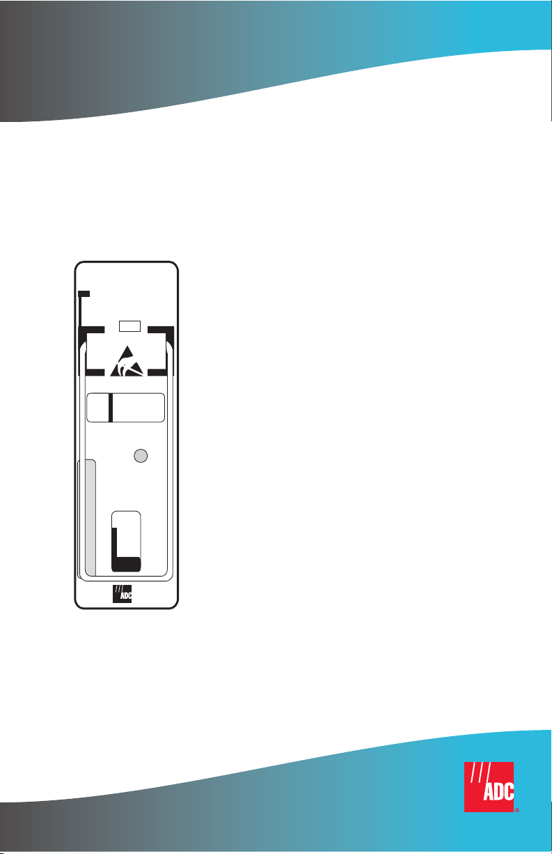
Figure 1 shows the front panel of the EDU-409 List 1, and Table 3 describes
the doubler unit components.
EDU-409
HiGain
DOUBLER
L
Status LED
STATUS
Configuration
number label
(located on side)
Figure 1. EDU-409 List 1 Front Panel
Table 3. Front Panel Components and Labels
Name Function
Status LED Indicates operational status of doubler. See Table 4 on page 9.
Configuration
number
6 January 26, 2000 EDU-409 List 1
Contains either a five-digit or six-digit warranty configuration number or
a standalone two or three-digit configuration number as follows:
Digit 1 = Last digit of shipment year
Digits 2 and 3 = Shipment month
Digits 4 and 5 = Configuration number
The configuration number can also be found on a small bar label that also
contains the Julian date code and part number. This gummed label may
be attached to the PC board or to the front panel.
Page 13

150-409-115-05, Issue 5 Installation
INSTALLATION
This section describes the compatibility and installation for the EDU-409
List 1.
COMPATIBILITY
The EDU-409 List 1 is compatible with the following ADC outdoor
enclosures:
• HRE-500, single-slot unit
• HRE-458, 10-slot unit
• HRE-819, 12-slot unit
INSTALLING THE EDU-409 LIST 1
To install the EDU-409 List 1 in an enclosure, perform the following steps
and refer to the enclosure installation manual for information about cabling,
proper connections, grounding, and line and local power.
This product incorporates static sensitive components.
Proper electrostatic discharge procedures must be followed.
To install the doubler unit, slide the doubler unit into the card guides for the
desired slot (see Figure 2 on page 8). Then push the unit into the enclosure
until it is seated in the card-edge connector. The unit should snap into place,
indicating that it is properly seated.
EDU-409 List 1 January 26, 2000 7
Page 14

Installation 150-409-115-05, Issue 5
Figure 2. Installing the EDU-409 List 1 in a Remote Enclosure
Some enclosures may require you to adjust the retaining bar
located on the front of the enclosure to secure the unit. Refer
to the appropriate ADC user manual for the enclosure.
Once the EDU-409 List 1 is installed in the enclosure, the front panel Status
LED flashes green if power is applied from an upstream line unit. When the
loops on both sides of the EDU synchronize, the LED constantly glows solid
green. Refer to the section titled “Alarms” on page 9 for more details on LED
operation.
8 January 26, 2000 EDU-409 List 1
Page 15

150-409-115-05, Issue 5 Alarms
ALARMS
The front panel of the EDU-409 List 1 contains a tri-color LED. The LED
color and activity provides information on system functionality (see Table 4).
Table 4. Front Panel Status Indicator
LED Description
Flashing Green once
per second
Flashing Green more
than once per second
Steady Green Indicates HDSL frame synchronization has been achieved
Flashing Red once per
second
Flashing Red more
than once per second
Flashing Yellow once
per second
Flashing Yellow more
than once per second
Indicates synchronization is being attempted between the
EDU-409 List 1 and the upstream (network) module.
Indicates synchronization is being attempted between the
EDU-409 List 1 and the downstream (customer) module.
between the EDU-409 List 1 and both the upstream and
downstream modules.
Indicates an HDSL Cyclic Redundancy Check (CRC) error has
occurred between the EDU-409 List 1 and the upstream module.
See "Technical Specifications" on page 21.
Indicates an HDSL CRC error has occurred between the
EDU-409 List 1 and the downstream module. See "Technical
Specifications" on page 21.
Indicates an NDU (Network Doubler Unit) loopback is in effect in
the EDU-409 List 1 towards the network. This tests the integrity of
the upstream span.
Indicates a CDU (EDU-409 List 1 to customer) loopback is in
effect in the EDU-409 List 1 towards the customer. This tests the
integrity of the downstream span.
EDU-409 List 1 January 26, 2000 9
Page 16

Loopback Operation 150-409-115-05, Issue 5
LOOPBACK OPERATION
When equipped with the EDU-409 List 1, a HiGain system can execute a
number of loopback commands. The loopbacks can be initiated from the ELU
craft port or from the ELU front-panel buttons.
For more information about doubler loopback commands, refer to the
appropriate ELU practices (see“Product Support” on page 23).
All NDU loopbacks are towards the network. All CDU loopbacks are towards
the customer. Figure 3 is a diagram of a HiGain loopback system.
Figure 3. HiGain Loopbacks
10 January 26, 2000 EDU-409 List 1
Page 17

150-409-115-05, Issue 5 Functional Description
FUNCTIONAL DESCRIPTION
HiGain uses the ADC Two-Binary, One-Quaternary (2B1Q) HDSL
transceiver system to establish two full-duplex 1040 kbps data channels
between the ELU and the ERU units. Each EDU-409 List 1 increases the
maximum range by approximately 3.66 km (12,000 feet) of 0.51-mm wire or
2.74 km (9,000 feet) of 0.4-mm wire per doubler.
A block diagram of the EDU-409 List 1 with pinouts is shown in Figure 4.
The doubler unit power supply uses the HDSL simplified line voltage to
produce +5 Vdc and +3 Vdc required by the EDU-409 List 1 electronics. The
power feed is passed on to the HDSL output pair, to power a second doubler
or a remote unit.
The maximum power dissipation of the doubler unit is 3 W.
Figure 4. Doubler Block Diagram
EDU-409 List 1 January 26, 2000 11
Page 18

Functional Description 150-409-115-05, Issue 5
DOUBLER ENCLOSURE CAPACITIES WITH FULL
OLAR LOAD
S
The EDU-409 List 1 can be housed in a variety of outdoor enclosures
manufactured by ADC and other vendors. The number of doublers used in
any of the enclosures depends on the maximum outside ambient temperature.
The doubler capacities for several of these standard enclosures is listed in
Table 5 on page 13 and Table 6 on page 14. The capacities listed in Table 6
(for both indoor and outdoor enclosures) are based on a maximum outside
temperature of +46.1 °C (+115 °F). Consult ADC for the latest deployment
rules when using the enclosures at ambient temperatures above +46.1 °C.
These requirements comply with Bellcore standards, which
require HDSL equipment place in outdoor cabinets to operate
in a temperature, outside the housing, of -40 °F (-40 °C) with
no solar load and +115 °F (+46.1 °C) with a maximum solar
load and maximum power dissipation.
Full solar load is equal to maximum sunlight exposure as
defined in Bellcore’s Technical Advisory TR-TSY-000057.
12 January 26, 2000 EDU-409 List 1
Page 19

150-409-115-05, Issue 5 Functional Description
The capacities listed for the indoor enclosures in Table 5 assume no solar
load. The capacities listed for the outdoor enclosures in Table 6 assume a full
solar load as described above. The “Recommended Slot Assignment for
Maximum Capacity” column assigns slots according to the following thermal
stress reduction rules:
1 Always leave at least one empty slot between adjacent doublers. The
adjacency rule only applies to the left- and right-hand sides of the
doubler. The top of one unit can be adjacent to the bottom of another,
though the latter configuration should be avoided if possible.
Rule 1 does not apply to the HRE-458 and HRE-819 enclosures
since these products have the required slot separations
already built into their design.
2 Allow as much room as possible between doublers on all four sides.
Slot assignments that do not follow the recommended
configurations in Table 5 and Table 6 are permissible as long
as the above two rules are applied. Otherwise, damage may
occur to doubler units.
Table 5. Indoor Enclosure Capacities
Vendor Description Model #
CHARLES Indoor wall mount CiAC2300 7 7
CiAC2002 2 2
SPC Indoor rack and wall
mount
EDU-409 List 1 January 26, 2000 13
4400-09 18 18
EDU-409 List
1 Doubler
Capacity
239 T1
Repeater
Capacity
Page 20

Functional Description 150-409-115-05, Issue 5
Table 6. Outdoor Enclosure Capacities with Full Solar Load
Vendor Description Model No.
AT&T Outdoor D ual
819 12 25 1, 3, 5, 9, 11, 13, 15,
chamber
pole/wall
mount
AT&T Outdoor 841
cabinet
AT&T Outdoor
27A, B, C or
D shelf
809 6 12 All even or all
cabinet
ALCATEL Outdoor
canister,
pole/wall
mount
621204 5 12 1, 3, 5, 8, 10
621205 7 25 2, 5, 9, 12, 14, 17, 24
621206 9 50 2, 5, 9, 12, 14, 17, 24,
EDU-409
List 1
Doubler
Capacity
11 per
shelf/44
total
239 T1
Repeater
Capacity
25 per
shelf/100
total
Recommended Slot
Assignment for
Maximum
Capacity
17, 19, 21, 23, 25
(See Figure 5 on
page 17)
1, 3, 6, 8, 10, 11, 12,
16, 18, 20, 23, 25
odd-numbered slots.
31, 47
CHARLES Outdoor
canister,
pole/wall
mount
CiAC4306 3 6 All even or all
odd-numbered slots.
CiAC3300 2 3 1, 3
CiAC5312 5 12 All even or all
odd-numbered slots.
CiAC5325 7 25 1, 3, 9, 11, 13, 17, 22
CiAC5350 9 50 1, 5, 9, 14, 16, 23, 32,
41, 49
SIERRA Outdoor
canister,
3011 3 6 All even or all
odd-numbered slots.
pole/wall
mount
SUNRISE 3021 3 5 1, 3, 5
SPC Outdoor
canister,
pole/wall
mount
ADC Outdoor
7130-08FP 3 8 1, 3, 6
7130-12FP 5 12 1, 3, 5, 7, 11
7130-25FP 7 25 2, 4, 8, 11, 14, 16, 25
HRE-458 8 10 1, 2, 4, 5, 7, 8, 9, 10
canister,
pole/wall
mount
14 January 26, 2000 EDU-409 List 1
Page 21

150-409-115-05, Issue 5 Functional Description
Table 6. Outdoor Enclosure Capacities with Full Solar Load (Cont.)
Vendor Description Model No.
ADC Outdoor
HRE-819 12 12 All slots
dual
chamber,
pole/wall
mount
Some of the Table 6 capacities are conservative estimates.
Ongoing tests at ADC may result in increasing some of these
estimates.
Thermal constraints must be observed to ensure reliable
service for worst-case conditions.
EDU-409
List 1
Doubler
Capacity
239 T1
Repeater
Capacity
Recommended Slot
Assignment for
Maximum
Capacity
EDU-409 List 1 January 26, 2000 15
Page 22

Functional Description 150-409-115-05, Issue 5
ALTERNATIVE DOUBLER ENCLOSURE
APACITIES
C
The number of doublers can be increased by two for applications where the
enclosures are underground or not exposed to direct sunlight. However, any
increase in capacity is still subject to rule 1 on page 4.
The doubler capacity numbers listed for each outdoor
enclosure must be reduced by one for every additional
+5 °F (+2.8 °C) rise, or any fraction thereof, in outside ambient
temperatures above +115 °F (+46.1 °C).
The capacities can be increased by one for every additional
+5 °F (+2.8 °C) reduction in outside ambient temperatures
above +115 °F (+46.1 °C).
Reduce the doubler capacity by one for every two doublers that do not have
an empty slot between them. If the application allows seven doublers, but two
are directly adjacent to each other, then the total capacity must be reduced to
six.
Standard T1 repeaters can be installed in the same enclosure with doubler
units. If this method is used, the maximum number of doublers that can
occupy the same case with the standard repeaters must be reduced by one for
every four T1 repeaters (or fractions thereof) installed. T1 repeaters located
with doublers in outdoor enclosures should be placed in slots that are not
adjacent to the doublers.
Rule 1 in the section titled “Doubler Enclosure Capacities with
Full Solar Load” on page 12 does not apply if the adjacent slot
is occupied by a T1 repeater.
16 January 26, 2000 EDU-409 List 1
Page 23
150-409-115-05, Issue 5 Functional Description
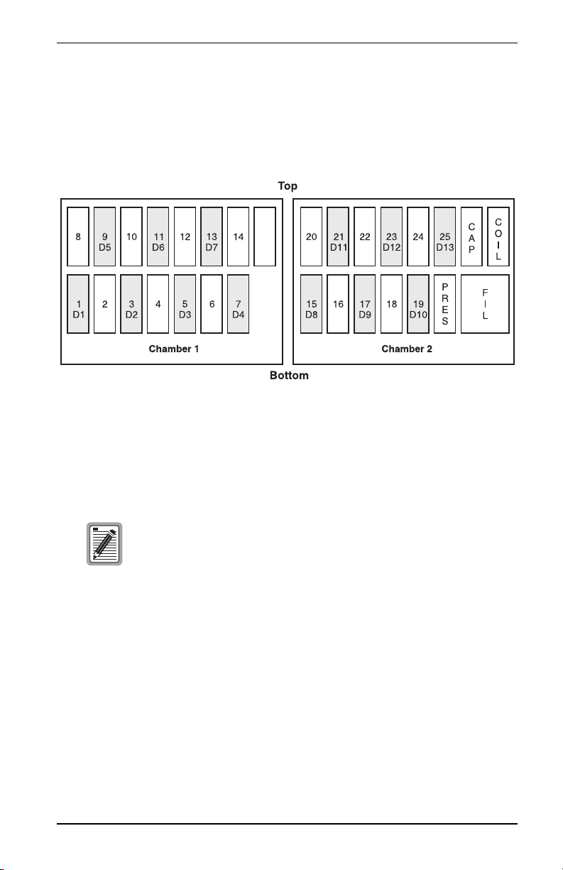
The AT&T 819 enclosure has two, individual isolated chambers as shown in
Figure 5. Slots 1 through 14 are in one chamber. The other chamber contains
slots 15 through 25 along with the Pressure (PRES), Filter (FIL), Capacitor
(CAP), and COIL slots.
.
Figure 5. AT&T 819 Enclosure
The AT&T 819 can house up to 13 EDU-409 List 1 doublers in the slots
designated as D1 through D13 as shown in Figure 5.
Because the length of the EDU-409 List 1 extends beyond the
range that older AT&T 819 repeater apparatus covers can
accommodate, the cover must be replaced by a deeper cover.
EDU-409 List 1 January 26, 2000 17
Page 24

Functional Description 150-409-115-05, Issue 5
MICRO DOUBLER CAPACITY DEPLOYMENT
ULES
R
The deployment rules for micro doubler capacity are summarized below:
1 Use Table 5 on page 13 for indoor enclosures.
2 Use Table 6 on page 14 for outdoor enclosures with Full Solar Load for
ambient temperatures up to 46.1 °C maximum.
3 The capacities shown in Table 6 can be increased by two for non-solar
load (shaded or manhole applications).
4 Decrease capacities in Table 6 by one for every 2.7 °C increase, or
fraction thereof, in ambient temperatures above 46.1 °C.
5 Increase the capacities by one for every full +2.7 °C reduction in ambient
temperature below 46.1 °C.
6 Decrease any outdoor capacity by one for every four E1 repeaters, or
fraction thereof, that are installed with the doublers.
7 For all outdoor applications, decrease the capacity by one for every two
adjacent doublers that are not separated by at least one empty slot.
18 January 26, 2000 EDU-409 List 1
Page 25

150-409-115-05, Issue 5 Ground Faults
GROUND FAULTS
G
ROUND FAULT DETECTION
The EDU-409 List 1 has ground fault detection (GFD) circuits. When used
with HiGain line units, ground faults occurring at any point along any span
are immediately detected. Ground fault conditions shut the HiGain circuit
down. The line unit periodically tries to apply power to the first span to
determine whether the fault condition is still present. As long as the condition
exists, the power cycling and ground fault protection continues. To
discontinue the ground fault protection, locate and repair the fault in the
cable.
Circuits containing both the EDU-409 List 1 and older doublers without a
GFD circuit also support this new ground fault detecting feature, provided the
doubler nearest the ELU is an EDU-409 List 1.
The operation of the ground fault circuit requires that the
doubler enclosure ground plane is properly connected to
earth ground.
EDU-409 List 1 January 26, 2000 19
Page 26

Ground Faults 150-409-115-05, Issue 5
GROUND FAULT ISOLATION
Solutions for common problems that may occur with the EDU-409 List 1 are
listed in Table 7.
Table 7. Fault Isolation Guide
Problem Solution
LED does
not light
LED
continues to
flash green
once a
second
EDU-409
List 1 loses
power
HDSL line
power only
appears in
very short
bursts
EDU-409
List 1 shuts
off after
Span 1
comes up
1 Verify that the ELU is installed and operational in the Central Office.
2 Verify proper cabling between the doubler enclosure and the Central
Office.
3 Measure 100 to 200 Vdc between pins 5 or 6 and 8 or 9. This voltage
peaks every 15 to 30 seconds as the ELU cycles between self test and
line power. If less than 100 Vdc is present, check the cabling or the ELU.
Only the line units mentioned in the Description and Features section
can be used to power doublers. Other ELU models may not provide
reliable operation and should not be used.
Synchronization is being attempted with the upstream unit.
The ELU at the Central Office is not present. Measure the resistance of the
HDSL input loop. Resistance should be normal loop resistance plus the
25 Ω signature of the ELU.
A grounded pair is being detected by either the ELU or EDU-409 List 1 in
Span 1. This causes the unit’s ground fault detection (GFD) circuit to
trigger, which forces the HDSL line voltage off immediately after it cycles
on. Remove the ELU and EDU-409 List 1 and check for cable ground faults
in Span 1. The doubler’s GFD circuit can easily be checked by grounding
any of the loop connectors to the doubler. This forces the circuit down
immediately. If the circuit stays up, either the GFD circuit is defective or the
EDU-409 List 1 is not properly grounded.
A grounded pair is being detected by the EDU-409 List 1 in Span 2. Remove
EDU-409 List 1 and check for ground fault in Span 2.
20 January 26, 2000 EDU-409 List 1
Page 27

150-409-115-05, Issue 5 Technical Specifications
TECHNICAL SPECIFICATIONS
HDSL
Line Code 1040 kbps, 2B1Q full duplex
Output +13 dBm
Line Impedance 135
Resistive Signature Input/Output: 25 Ω (maximum)
Start-up Time (per span) 15 seconds (typical), 30 seconds
Line Clock Rate
Internal Stratum 4 clock
Power Consumption
3.0 W (nominal), 3.2 W (maximum)
Maximum Provisioning Loss
35 dB @ 260 kHz, 135 Ω
Ω
Line Output DC: 25 Ω (maximum)
(maximum)
Wander and Jitter
Nominal - The absence of an HDSL framer from the EDU-409 List 1
reduces the Doubler Unit’s effect on a circuit’s overall wander and jitter to
second order insignificance when compared to the wander and jitter of
other circuit modules.
Latency
80 microseconds (maximum either direction)
Mounting
Single 239 T1 Mechanics slot
Electrical Protection
Secondary surge and power cross protection on all HDSL ports
EDU-409 List 1 January 26, 2000 21
Page 28

Technical Specifications 150-409-115-05, Issue 5
Environmental
Operating Temperature -40 °C (-40 °F) to +70 °C (+158 °F)
Operating Humidity
(non-condensing)
Operating Temperature in
Outside Enclosures
Operating Elevation 60.96 m (200 feet) below sea level to
5% to 95%
Complies with Section 10.2.1.3 of
TA-NWT-001210
3.96 km (13,000 feet) above sea level
Dimensions
Height 6.6 cm (2.6 inch)
Width 1.9 cm (0.75 inch)
Depth 16.5 cm (6.5 inch)
Weight 1.76 kg (0.8 lbs)
Standards Compliance
EN-60950 Low Voltage
22 January 26, 2000 EDU-409 List 1
Page 29

150-409-115-05, Issue 5 Product Support
PRODUCT SUPPORT
ADC Customer Service Group provides expert pre-sales and post-sales
support and training for all its products.
Technical support is available 24 hours a day, 7 days a week by contacting
the ADC Technical Assistance Center (TAC).
Sales Assistance
800.366.3891 extension 73000
(USA and Canada)
952.917.3000
Fax: 952.917.3237
Systems Integration
800.366.3891, extension 73000
(USA and Canada)
952.917.3000
ADC Technical Assistance Center
800.638.0031
714.730.3222
Fax: 714.730.2400
Email: wsd_support@adc.com
Online Technical Support
Online Technical Publications
• Quotation Proposals
• Ordering and Delivery
• General Product Information
• Complete Solutions (from concept to
installation)
• Network Design and Integration Testing
• System Turn-Up and Testing
• Network Monitoring (upstream or downstream)
• Power Monitoring and Remote Surveillance
• Service/Maintenance Agreements
• Systems Operation
• Technical Information
• System/Network Configuration
• Product Specification and Application
• Training (product-specific)
• Installation and Operation Assistance
• Troubleshooting and Repair/Field Assistance
• www.adc.com/Knowledge_Base/index.jsp
• www.adc.com/library1/
Product Return Department
800.366.3891 ext. 73748 or
952.917.3748
Fax: 952.917.3237
Email: repair&return@adc.com
All 800 lines are toll-free in the USA and Canada.
EDU-409 List 1 January 26, 2000 23
• ADC Return Material Authorization (RMA)
number and instructions must be obtained
before returning products.
Page 30

Abbreviations 150-409-115-05, Issue 5
ABBREVIATIONS
AIS Alarm Indicator Signal
CAP Capacitor
CDU EDU to Customer loopback
CRC Cyclic Redundancy Check
DDS Digital Data Service
EDU HiGain E1 Doubler Unit
ELU HiGain E1 Line Unit
ERU HiGain E1 Remote Unit
FIL Filter
GFD Ground Fault Detection
HCDS High Capacity Digital Service
HDSL High bit-rate Digital Subscriber Line
HRE HiGain Remote Enclosure
KBPS Kilo (thousand) Bits Per Second, sometimes written Kb/s
MBPS Mega (million) Bits Per Second, sometimes written Mb/s
NDU EDU to Network Loopback
POTS Plain Old Telephone Service
PRES Pressure
RMA Return Material Authorization
SPLB Special Loopback
24 January 26, 2000 EDU-409 List 1
Page 31

150-409-115-05, Issue 5 Glossary
GLOSSARY
American Wire
Gauge
2B1Q Two-Binary, One-Quaternary. Line coding used for HDSL.
Cable Binder
Group
Bridged Tap A pair of wires connected in parallel across a single line to form a “T”
Loop A length of twisted-pair copper wire connecting the local unit of an
The standard used to describe wire size. The diameter of the wire
increases as the gauge decreases. 26 gauge is 4 mm (0.0157') in
diameter, 24 gauge is 51 mm (0.0201'), and so on.
A group of 25 pairs of wires.
configuration.
HDSL circuit to the remote unit.
EDU-409 List 1 January 26, 2000 25
Page 32

Glossary 150-409-115-05, Issue 5
26 January 26, 2000 EDU-409 List 1
Page 33

150-409-115-05, Issue 5 CISPR-A ComplianceCertification and Warranty
CERTIFICATION AND WARRANTY
CISPR-A COMPLIANCE
This unit complies with the limits for CISPR-A for radiated emissions. These limits are designed to
provide reasonable protection against harmful interference when the equipment is operated in a
commercial environment. This equipment generates, uses, and can radiate radio frequency energy and,
if not installed and used in accordance with the instruction manual, can cause harmful interference to
radio communications. Operation of this equipment in a residential area is likely to cause harmful
interference, in which case the user will be required to correct the interference at his own expense. Refer
to the installation section of the appropriate instruction manual for the unit you are installing to get
information on cabling, correct connections and grounding
LIMITED WARRANTY
ADC DSL Systems, Incorporated (“ADC”) warrants that, for a period of sixty (60) months from the
date of shipment, the hardware portion of its products will be free of material defects and faulty
workmanship under normal use. ADC's obligation, under this warranty, is limited to replacing or
repairing, at ADC's option, any such hardware product which is returned during the 60-month w arranty
period per ADC's instructions and which product is confirmed by ADC not to comply with the
foregoing warranty.
ADC warrants that, for a period of 90 days from the date of purchase, the software furnished with its
products will operate substantially in accordance with the ADC published specifications and
documentation for such software. ADC’s entire liability for software that does not comply with the
foregoing warranty and is reported to ADC during the 90-day warranty period is, at ADC’s option,
either (a) return of the price paid or (b) repair or replace of the software. ADC also warrants that, for a
period of thirty (30) days from the date of purchase, the media on which software is stored will be free
from material defects under normal use. ADC will replace defective media at no charge if it is returned
to ADC during the 30-day warranty period along with proof of the date of shipment.
The transportation charges for shipment of returned products to ADC will be prepaid by the Buyer.
ADC will pay transportation charges for shipment of replacement products to Buyer, unless no trouble
is found (NTF), in which case the Buyer will pay transportation charges.
ADC may use reconditioned parts for such repair or replacement. This warranty does not apply to any
product which has been repaired, worked upon, or altered by persons not authorized by ADC or in
ADC's sole judgment has subjected to misuse, accident, fire or other casualty, or operation beyond its
design range.
Repaired products have a 90-day warranty, or until the end of the original warranty period—whichever
period is greater.
ADC DISCLAIMS ALL OTHER WARRANTIES, EITHER EXPRESS OR IMPLIED, INCLUDING
BUT NOT LIMITED TO IMPLIED WARRANTIES OF MERCHANTABILITY AND FITNESS
FOR A PARTICULAR PURPOSE, WITH RESPECT TO ITS PRODUCTS AND ANY
ACCOMPANYING WRITTEN MATERIALS. FURTHER, ADC DOES NOT WARRANT THAT
SOFTWARE WILL BE FREE FROM BUGS OR THAT ITS USE WILL BE UNINTERRUPTED OR
REGARDING THE USE, OR THE RESULTS OF THE USE, OF THE SOFTWARE IN TERMS OF
CORRECTNESS, ACCURACY, RELIABILITY OR OTHERWISE.
EDU-409 List 1 January 26, 2000 27
Page 34

ADC DSL Systems, Inc.
14402 Franklin Avenue
Tustin, CA 92780-7013
Tel: 714.832.9922
Fax: 714.832.9924
Technical Assistance
Tel: 800.638.0031
Tel: 952.917.3222
Fax: 714.730.2400
ISO9001/TL9000
DNV Certificat ion, Inc.
REGISTERED FIRM
DOCUMENT: 150-409-115-05, ISSUE 5
´,4a¶0(¨
1220650
 Loading...