

Page 1

HCB J Precious Metals and Density
Balance
(P.N. 308660002 Revision D1, June 2013)
Adam Equipment
Software 4.2 and above
© Adam Equipment Company 2013
Page 2

© Adam Equipment Company 2013
Page 3

CONTENTS
1.0 INTRODUCTION .......................................................................................................2
2.0 SET UP......................................................................................................................2
2.1 HCB J123, SETTING UP YOUR BALANCE.........................................................2
2.2 HCB J302, J1002 and J2002 SETTING UP YOUR BALANCE ............................6
2.3 PREPARING FOR USE........................................................................................10
2.4 KEYPAD / DISPLAY FUNCTION..........................................................................12
2.5 REAR PANEL.......................................................................................................13
2.6 INTERNAL RECHARGEABLE BATTERY............................................................13
3.0 LOCATING AND PROTECTING YOUR BALANCE.................................................14
4.0 BASIC OPERATION................................................................................................15
4.1 TURNING ON THE BALANCE.............................................................................15
4.2 ZEROING / TARE.................................................................................................15
4.3 WEIGHING...........................................................................................................15
4.4 WEIGHING UNITS ...............................................................................................15
5.0 DENSITY FUNCTION..............................................................................................16
5.1 WEIGHING A SAMPLE........................................................................................16
5.2 DISPLAY DENSITY..............................................................................................17
6.0 DENSITY PARAMETERS........................................................................................19
6.1 SELECTING THE ALLOY TO TEST.....................................................................19
6.2 TEST OPTIONS ...................................................................................................19
6.3 LIQUID AND TEMPERATURE PARAMETERS...................................................19
6.4 ALLOY PARAMETERS ........................................................................................20
7.0 PARAMETERS........................................................................................................23
7.1 ENABLING WEIGHING UNITS, F1 Unt.................................................................24
7.2 HOLD FUNCTION, F2 Hld .....................................................................................26
7.3 BACKLIGHT, F3 bL................................................................................................27
7.4 PRINTING PARAMETERS, F4 Ser .......................................................................27
7.5 AUTO POWER OFF, F5 OFF..................................................................................29
7.6 INTERNAL OR EXTERNAL CALIBRATION, F6 ICE ..............................................29
7.7 ADJUST THE VALUE OF THE INTERNAL MASS, F7 CA ......................................30
7.8 USER TECHNICAL PARAMETERS, F8 SEt ..........................................................31
8.0 USER CALIBRATION..............................................................................................32
9.0 SERIAL INTERFACE SPECIFICATIONS................................................................34
10.0
REMOTE DISPLAY..............................................................................................36
11.0
TEMPERATURE SENSOR ..................................................................................36
12.0
TROUBLE SHOOTING.........................................................................................37
12.1 ERROR MESSAGES ........................................................................................37
12.2 REPLACEMENT PARTS AND ACCESSORIES ...............................................38
13.0
SPECIFICATIONS................................................................................................39
13.1 TECHNICAL SPECIFICATIONS .......................................................................39
13.2 COMMON SPECIFICATIONS...........................................................................39
14.0
WARRANTY INFORMATION...............................................................................40
1
© Adam Equipment Company 2013
Page 4
1.0 INTRODUCTION
Thank you for purchasing your new HCB J Precious Metals and Density Balance. As
with our popular HighlandTM series of balances the HCB J has all the features you
really need: DC adapter with internal rechargeable battery, HandiCalTM calibration,
backlit display, and ShockProtectTM with overload indicator. With the RS-232
interface for communication with printers and computers, splash-proof keypad, and
sturdy plastic construction, the HCB J will be a balance you can rely upon. We hope
that you enjoy using your new balance.
2.0 SET
2.1 HCB
UP
J123,
SETTING UP YOUR BALANCE
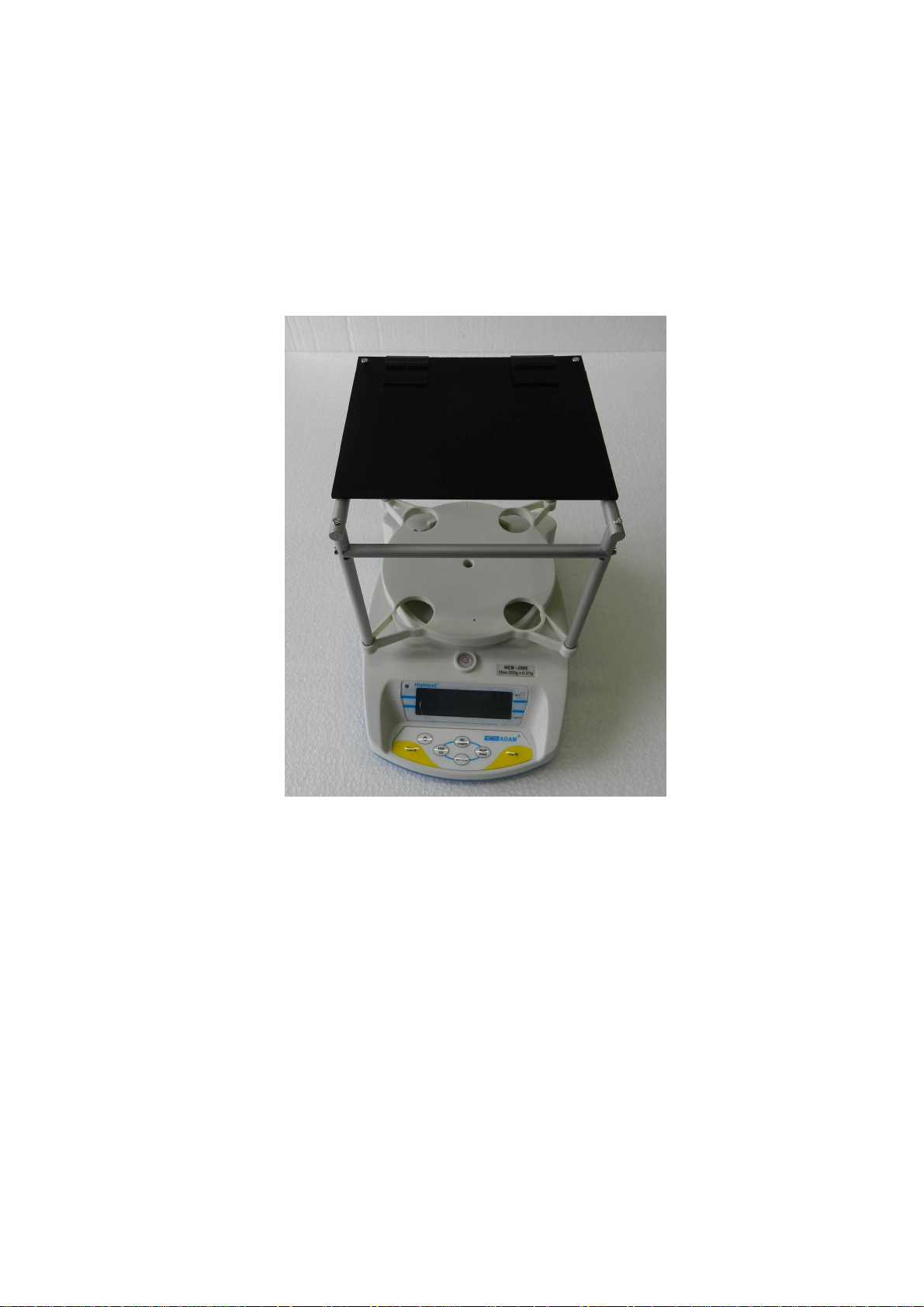
1) Remove the balance and all accessories from the packaging
2
© Adam Equipment Company 2013
Page 5
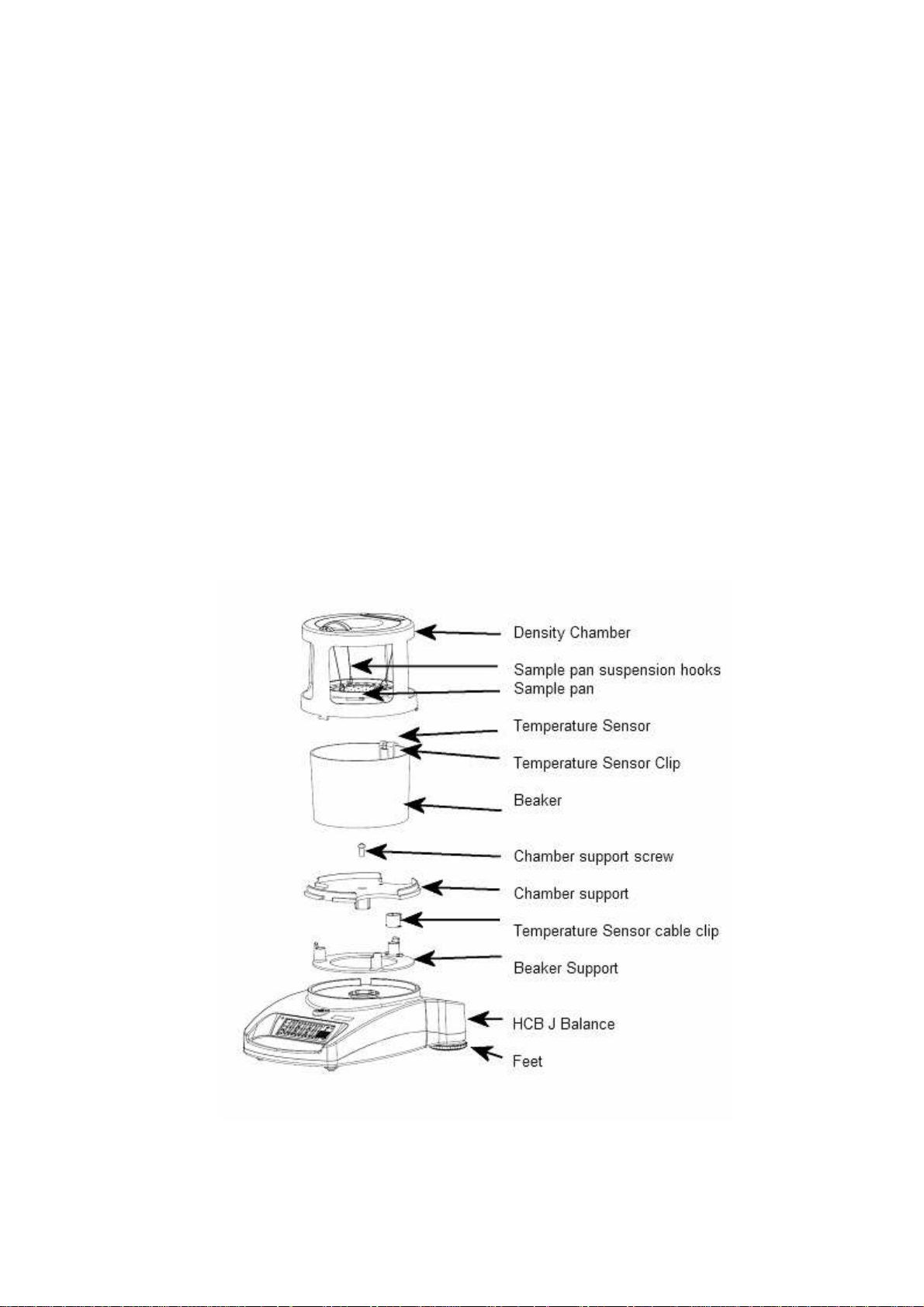
2) Remove the shipping protection screw and transit disc from the top of the
balance
3) Place the Beaker Support assembly onto the top housing with the
Temperature Sensor cable running down the back of the balance.
4) Lift the beaker away to the rear and locate the Density Chamber support into
the receptacle with the arrow facing the rear of the balance. Press gently to
insert it then secure the support in the center using the M4 x 20mm screw
which is packed in the accessory bag. Tighten only enough to secure the pan
support so that it does not rock in the receptacle.
3
© Adam Equipment Company 2013
Page 6

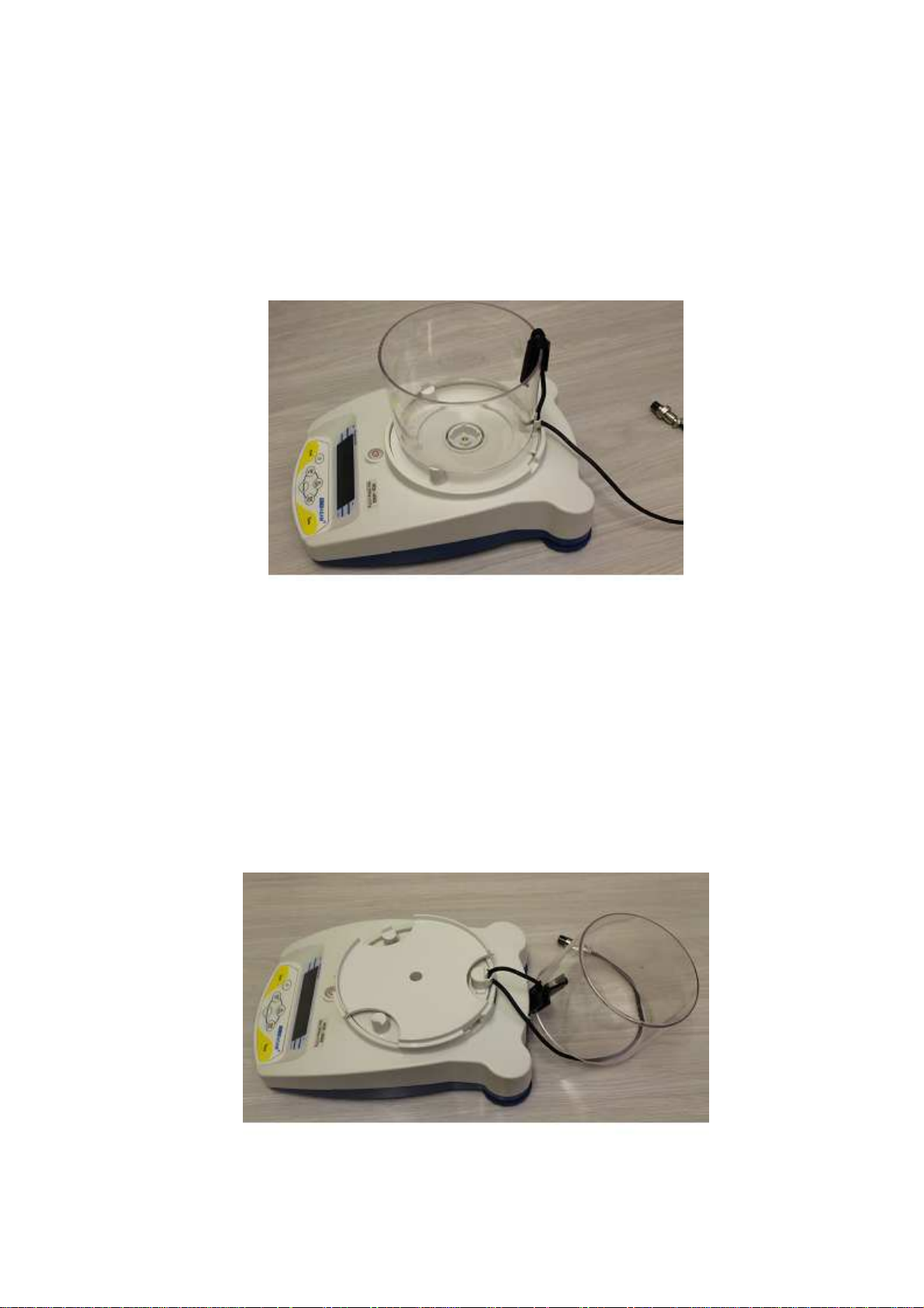
5) Replace the beaker onto the beaker support and pull the Temperature Sensor
cable through the clip to take up any slack or loose amount of cable.
6) Place the Density Chamber over the beaker with the handle of the lid at the
front and allowing for the sample pan to hang freely inside it. Secure the
Chamber to the support by rotating it gently clockwise and locking into the 3
tabs. Take care not to push down or use excessive force on the Chamber
when fixing as damage can be caused.
4
© Adam Equipment Company 2013
Page 7
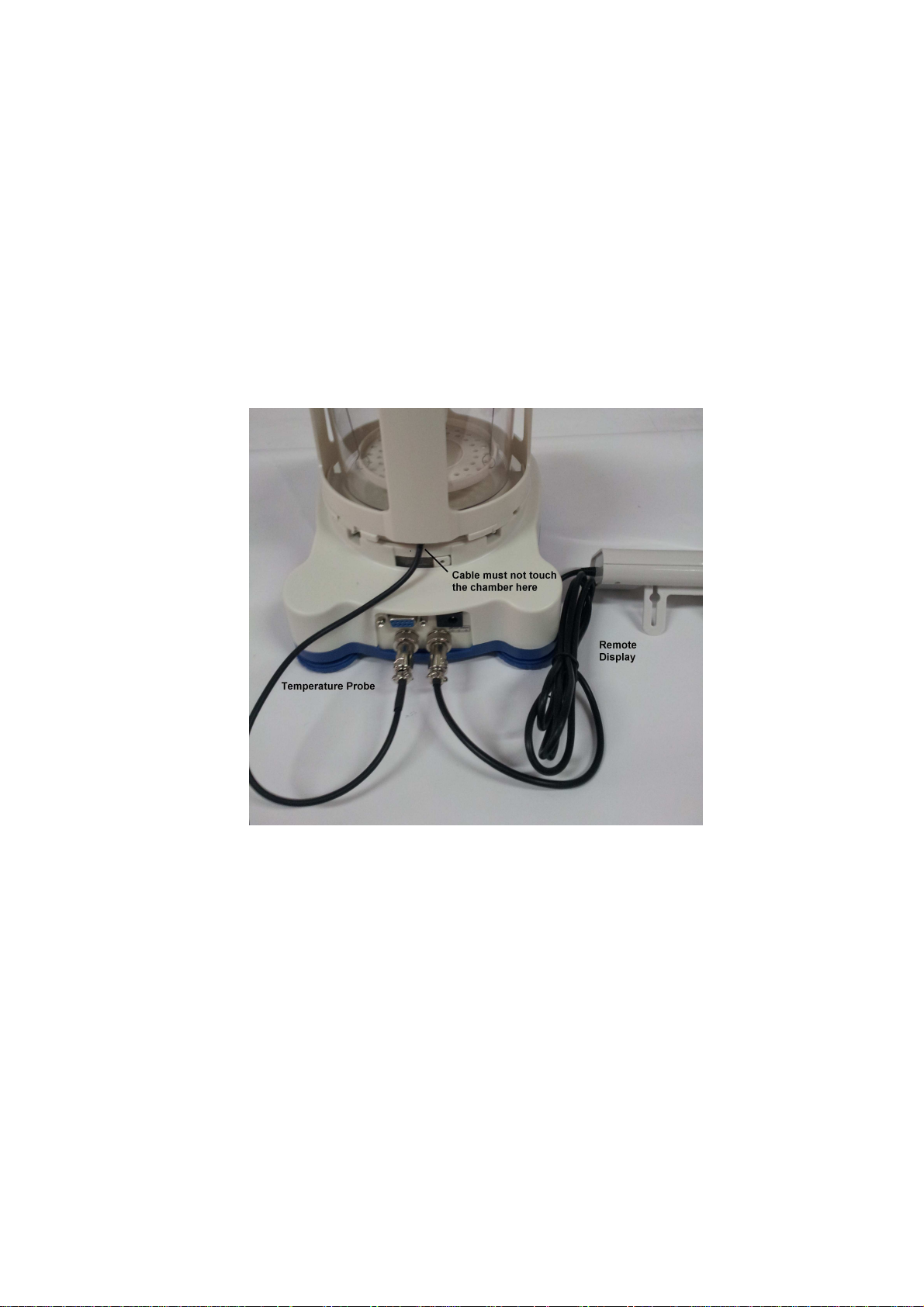
7) Plug the Temperature sensor into the 5 pin connector, and the remote
Indicator into the 6 pin connector at the rear of the balance.
8) Make sure again that the cable from the Temperature Sensor is tightly pulled
down through the clip and that it does not interfere or sit close to the Density
Chamber or Chamber support. If the cable is touching against any of these
parts it will result in incorrect weighing and karat calculations.
Position the balance and Remote Indicator in a convenient place and adjust the
feet to show a level state.
Switch on the balance whilst using battery power or connect the adaptor to the
mains supply.
5
© Adam Equipment Company 2013
Page 8

2.2 HCB
J302, J1002
AND
J2002 SETTING UP YOUR BALANCE
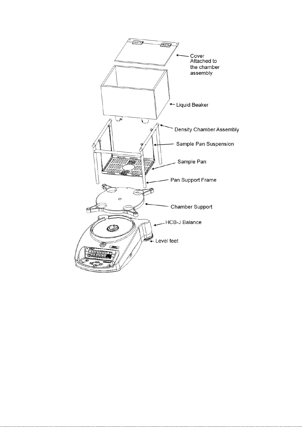
1) Remove the balance and all accessories from the packaging
2) The following items are included:
HCB J balance body
Power Supply
Weighing Chamber Assembly that includes
Sample Pan with suspension wires
Chamber Cover
Chamber Support
Liquid Beaker
Temperature Sensor
Temperature Sensor Clip
Remote Display
1ea M3 x 20 hex screw for Chamber Support Mounting
6
© Adam Equipment Company 2013
Page 9
7
© Adam Equipment Company 2013
Page 10
3) Remove the shipping protection screw and transit disc from the top of the
balance.
4) Place the Chamber Support assembly onto the top housing. Press gently to
insert it then secure the support in the center using the M4 x 20mm screw
which is packed in the accessory bag. Tighten only enough to secure the pan
support so that it does not rock in the receptacle.
8
© Adam Equipment Company 2013
Page 11
5) Place the liquid chamber onto the support. Ensure the line marking the water
level is to the front.
6) Place the temperature sensor onto the rear panel of the chamber. Pull the
Temperature Sensor cable through the clip to take up any slack or loose
amount of cable.
9
© Adam Equipment Company 2013
Page 12

7) Position the sample pan in the beaker area and connect the 4 suspension
wires to the rings in the support frame.
8) Plug the Temperature sensor into the 5 pin connector, and the remote
Indicator into the 6 pin connector at the rear of the balance.
9) Make sure again that the cable from the Temperature Sensor is tightly pulled
down through the clip and that it does not interfere or sit close to the Density
Chamber or Chamber support. If the cable is touching against any of these
parts it will result in incorrect weighing and karat calculations.
2.3 PREPARING
FOR USE
Position the balance and Remote Indicator in a convenient place and adjust the
feet to show a level state.
Switch on the balance whilst using battery power or connect the adaptor to the
mains supply.
10
© Adam Equipment Company 2013
Page 13

When you are preparing to do a Density Test it will be necessary to fill the
chamber with liquid. The choice of the type of liquid will be left for the user to
decide, however some solvents may not be compatible with the Polycarbonate of
the chamber or ABS of the Sample Pan. Test a small sample of the liquid on the
plastics before filling the beaker if unsure.
Fill the chamber with liquid lift the Chamber lid, or remove the Density Chamber
from its support and pour through a funneled container. The beaker should be
filled no higher than the maximum filling mark and needs to cover the metal part
of the Temperature Sensor cable. If the Chamber is removed refit the Chamber
once finished as described earlier. Care should be taken to not spill any liquid
onto or inside the balance as damage may occur which is not covered under the
normal warranty terms.
To fill the chamber whilst it is away from the balance it will be necessary to
remove the Temperature Sensor and clip from the chamber which then allows it
to be removed from the support. The cable will need to be pulled gently upwards
from below the Temperature Sensor clip to allow easy removal of the clip. When
re-fitting the Temperature Sensor and clip follow the previous instructions
ensuring the cable is pulled down into a tight position and lifted away from the
Chamber.
If water is used a few drops of liquid detergent may be added to the water to
improve the wetting ability and avoid trapped bubbles of air on the sample being
tested. Stir well to distribute the soap evenly.
When removing samples from the chamber use a towel to dry the samples so
the water does not splash onto the balance.
11
© Adam Equipment Company 2013
Page 14
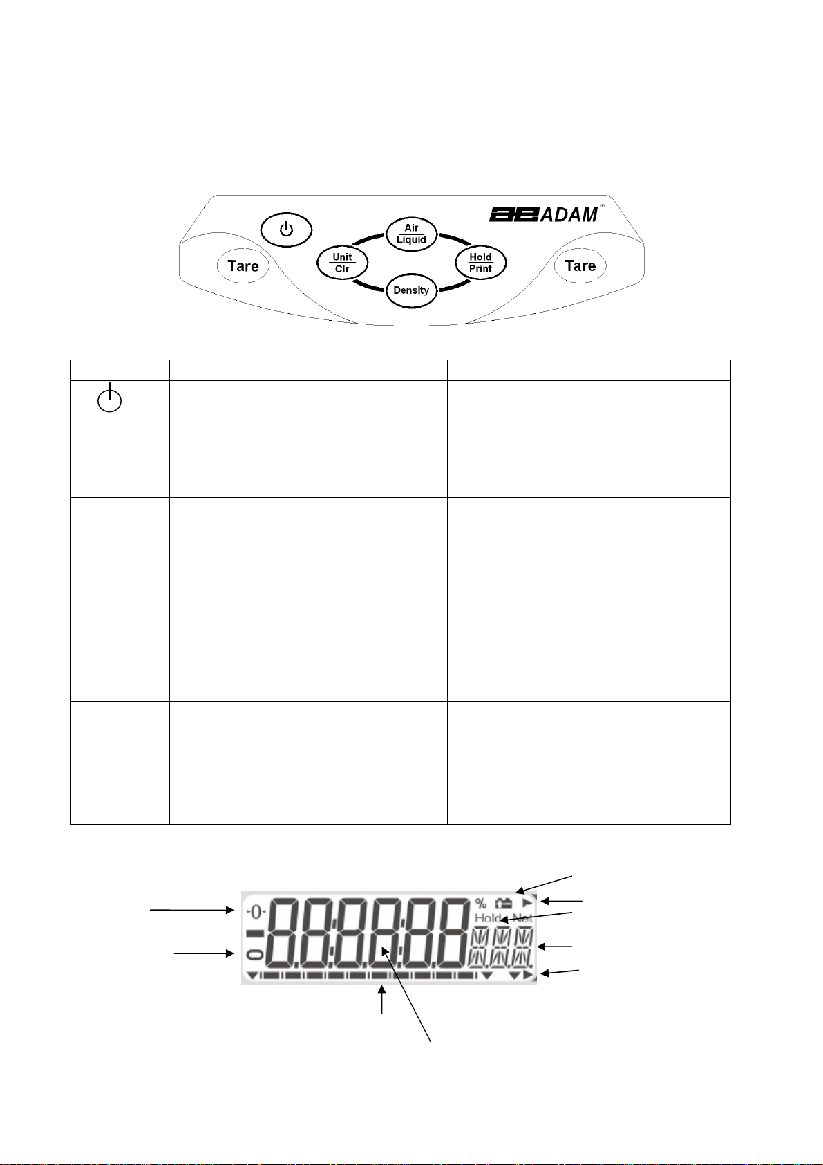
Zero
Stable
Capacity tracker
Weighing digits
Low battery indicator
Hold symbol
Weight in Air
2.4 KEYPAD
/
DISPLAY FUNCTION
The keypad and display have a number of features as shown and explained below:
KEYS PRIMARY FUNCTION SECONDARY FUNCTION
To turn the balance On or Off. ----
[On/Off]
[Tare]
[Hold/Print] Will set the current weight to be held
[Unit/Clr] Pressing this key will cycle through the
[Density] Pressing after the weights in the air
[Air/Liquid] Stores the current weight into the
Tares the balance and shows the net
weight value. Pressing the [Tare] again
will reset another tare value
on the display and will also send the
current weight data to the RS232
interface. When displaying the results
of the density test pressing
[Hold/Print] will send the results to
the interface.
weighing units which are enabled
and in the liquid have been stored will
show the density and karat results.
memory for density determination.
A secondary function of "Enter" is for
setting parameters or other functions.
When setting some parameters this key
will move the flashing digit to the right.
When in density mode pressing the
[Unit/Clr] will return the display to
normal weighing mode.
Whilst setting parameters it will show
the previous option, or decrease the
value of the flashing digit.
Whilst setting parameters it will show
the next option, or increase the value
of the flashing digit.
Alpha numeric display
Weight in Liquid
12
© Adam Equipment Company 2013
Page 15

2.5 REAR
PANEL
The rear panel has connectors for the power, RS232, remote display and
temperature sensor. For connections to these see the relevant sections.
2.6 INTERNAL
RECHARGEABLE BATTERY
The balance can be operated from the internal rechargeable battery or using an
adapter. The battery life is approximately 24 hours with the backlight off. Depending
on the usage of the backlight the lifetime of the battery will reduce and using the
remote display will lessen the battery life considerably.
The display will show an indication when the battery needs to be charged. To charge
the battery plug the adapter into the POWER socket at the back of the balance and
connect it to the mains power supply. The charging indicator at the left top corner of
the LCD will be on to show it is charging and will turn green when the battery is fully
charged.
13
© Adam Equipment Company 2013
Page 16

3.0 LOCATING
AND PROTECTING YOUR BALANCE
In order to keep your balance functioning at its best we suggest that you do the
following:
Avoid extremes of temperature. Do not place in
direct sunlight or near air conditioning vents.
Make sure the balance is located on a strong table
and free from vibration.
Avoid unstable power sources. Do not use near large
users of electricity such as welding equipment or
large motors. Do not let the balance battery go flat.
If you are not using it for a long time you should
charge the battery periodically to make sure the
battery does not lose its charge.
Keep free from vibration. Do not place near heavy or
vibrating machinery.
Avoid high humidity that might cause condensation.
Keep away from direct contact with water. Do not
spray or immerse the balance in water.
Do not place near open windows, air-conditioning
vents or fans that may cause a draft and unstable
readings.
Keep the balance clean. Do not stack material on the
balance / balance pan when it is not in use.
14
© Adam Equipment Company 2013
Page 17

4.0 BASIC
4.1 TURNING
OPERATION
ON
THE BALANCE
Plug in the unit using the adapter or use the internal rechargeable battery. It is
recommended that you charge the battery for at least 8 hours before first use.
1) To turn on press the [On/Off] key once and release. The balance will show the
software revision and the battery voltage then self-test before showing the
current temperature as measured or defined by the user. The balance will
show the stable sign and zero weight on the display and is now ready to use.
2) To turn the balance off after use press the [On/Off] key again. There is an
auto power-off function that will automatically turn the unit off if not used for
a period of time; this can be set in the parameters section.
4.2 ZEROING
/
TARE
You can press the [Tare] key to set a new zero point and show a zero reading. This
may be necessary if the weight reading is not indicating zero with nothing on the
pan. The zero indicator will show up in the upper left corner of the LCD.
If you are using a container whilst weighing then you can place this on the weighing
pan and press the [Tare] key. Providing the container weight is more than 4% of the
maximum capacity of the balance the display will show a zero reading and NET will
light up on the display. You can then weigh your sample in the container. Taring a
container will reduce the maximum weighing capacity available of the balance.
4.3 WEIGHING
To determine the weight of a sample place the sample in the container. The display
will show the weight of the sample and the unit of weight currently in use. The
stable indicator will light up when the reading is stable.
4.4 WEIGHING
UNITS
To change the weighing units press [Unit/Clr] which will cycle through the options of
units that are enabled. See Parameters 7.1 Enabling Weighing Units to enable or
disable the weighing units.
15
© Adam Equipment Company 2013
Page 18

5.0 DENSITY
FUNCTION
Once the HCB J is prepared for a density test and the parameters have been set for
doing the Density Determination (see section 6) the following procedure is used to
weigh the sample in air, and then again in water or another liquid, allowing you to
determine the density of the sample and if applicable a determination of the purity
(karat) of the gold in the sample.
The Hold function must be enabled (see section 7.2) for the Density function to
operate correctly. The Density parameters (see Section 6.0) should be checked
before doing a test as the results are dependent on the liquid and alloy settings.
NOTE: To perform a density only test set the parameters for density test (Section 6)
to Silver (Ag), Set Hold to Automatic (Hd Au), Select water for the liquid (H2O) and
automatic temperature detection (Auto tmP). Then when doing the density test only
the density of the sample will be displayed.
5.1 WEIGHING
A
SAMPLE
Place the sample to be weighed in air on top of the lid of the Density Chamber and
allow the weight displayed to become stable. If the Hold function is set to manual
press the [Hold/Print] key. The capacity tracker at the bottom of the display will
move from right to left and when ready the display will show “HOLD”. If the Hold
function is set to automatic you are not required to press the [Hold/Print] key once
the weighing in air becomes stable.
After the Hold symbol is shown press the [Air/Liquid] key to store this value. Wait
for the Weight in Air indicator to be displayed before you proceed to the next step.
Remove the sample and ensure the balance returns to zero. If necessary press the
[Tare] key to zero the display.
Open the lid of the Density Chamber and carefully place the sample in the liquid on
the suspended pan. It may be helpful to shake the sample gently to dislodge any air
bubbles.
Close the lid of the Density chamber and allow the weight displayed to become
stable. If the Hold function is set to manual press the [Hold/Print] key. The capacity
tracker at the bottom of the display will move from right to left and when ready the
16
© Adam Equipment Company 2013
Page 19

display will show “HOLD”. If the Hold function is set to automatic you are not
required to press the [Hold/Print] key once the weighing in liquid becomes stable.
After the Hold symbol is shown press the [Air/Liquid] key to store this value. The
Weight in Liquid indicator will be shown at which point the sample can be removed.
If when weighing in air the weighing unit starts to flash a message of “ADD”, this
informs you that the weight of the sample may not be enough to give accurate
calculations and therefore it is recommended that a larger sample weight is used.
At this point the USER can add more weight to the lid until the flashing stops which
signifies that the minimum sample weight required has been met.
Once the flashing stops remove the sample from the lid of the chamber, press the
[Unit/Clr] key and make sure the display shows zero, place the sample back onto
the lid to start the process again.
Minimum sample weights are as follows:
HCB J123 – 2g
HCB J302 – 2g
HCB J1002 – 5g
HCB J2002 – 10g
* Please note that if extra weight is not added to meet the minimum sample weight
requirements when the message “ADD” is being displayed, the balance will continue
to calculate based on the sample weight at that time.
5.2 DISPLAY
DENSITY
Press the [Density] key to display the density of the sample, ie- “14.2 den”
Press the [Density] key a second time to display the Karat value for the sample. For
example if gold with silver is selected the display would show “ 14
for other display options the display might show “ 14
KCu
” for gold with copper, “ 14
KAg
”. Like wise
K11
” for gold with silver and copper in a 1:1 ratio, “ 14
and “ 14
K o
” for other density of alloys that might be used. See section 6.2 for
KMn
” for a ratio other than 1:1
details of setting the alloy options.
Press the [Density] key a third time to display the content of gold determined during
the test, ie- “583 Cnt”. If the density value is outside of the expected range (see
17
© Adam Equipment Company 2013
Page 20

table below), the karat value and content value will not be displayed. An error
message will be shown. Only the density value will be available.
To return to normal weighing press the [Unit/Clr] key. To run another test ensure
all weight is removed from the pan support in the water and from the Density
Chamber.
Gold Density values used for Karat determination for silver and copper alloys.
GOLD
KARAT
7K 292/1000 12.14(12.01-12.27) 10.60(10.46-10.73) 11.32(11.18-11.45)
8K 333/1000 12.42(12.28-12.55) 10.89(10.74-11.03) 11.60(11.46-11.74)
9K 375/1000 12.70(12.56-12.84) 11.19(11.04-11.34) 11.90(11.75-12.04)
10K 417/1000 13.00(12.85-13.14) 11.51(11.35-11.67) 12.21(12.05-12.36)
11K 458/1000 13.31(13.15-13.46) 11.85(11.68-12.02) 12.54(12.37-12.70)
12K 500/1000 13.64(13.47-13.80) 12.22(12.04-12.40) 12.89(12.71-13.06)
13K 542/1000 13.98(13.81-14.15) 12.61(12.41-12.80) 13.26(13.07-13.44)
14K 584/1000 14.34(14.16-14.52) 13.02(12.81-13.22) 13.65(13.45-13.84)
15K 625/1000 14.72(14.53-14.91) 13.46(13.23-13.68) 14.06(13.85-14.27)
16K 667/1000 15.12(14.92-15.32) 13.93(13.69-14.16) 14.50(14.28-14.72)
17K 708/1000 15.54(15.33-15.75) 14.43(14.17-14.69) 14.97(14.73-15.20)
18K 750/1000 15.99(15.76-16.21) 14.98(14.70-15.25) 15.47(15.21-15.72)
19K 792/1000 16.46(16.22-16.70) 15.56(15.26-15.86) 16.00(15.73-16.27)
20K 834/1000 16.97(16.71-17.22) 16.19(15.87-16.51) 16.57(16.28-16.86)
21K 875/1000 17.50(17.23-17.77) 16.88(16.52-17.23) 17.18(16.87-17.49)
22K 917/1000 18.07(17.78-18.36) 17.63(17.24-18.01) 17.84(17.50-18.18)
23K 958/1000 18.68(18.37-19.16) 18.44(18.02-19.09) 18.55(18.19-19.12)
24K 1000/1000 19.32(19.17-19.48) 19.32(19.10-19.54) 19.32(19.13-19.51)
Typical
CONTENT
SILVER(Ag) COPPER(Cu) Ag:Cu=1:1
Platinum Density Values used for determination of Platinum purity
Pt Content
1000 1000/1000(975-1025)
950 950/1000(925-975) 20.04(19.40-20.72) 20.64(20.26-21.04) 20.34(19.82-20.88)
900 900/1000(875-925) 18.8(18.24-19.40) 19.88(19.54-20.26) 19.33(18.87-19.82)
850 850/1000(825-875) 17.71(17.21-18.24) 19.18(18.86-19.54) 18.42(18.00-18.87)
800 800/1000(775-825) 16.73(16.29-17.21) 18.53(18.24-18.86) 17.6(17.21-18.00)
750 750/1000(725-775) 15.86(15.46-16.29) 17.92(17.65-18.24) 16.84(16.48-17.21)
700 700/1000(675-725) 15.08(14.71-15.46) 17.37(17.10-17.65) 16.14(15.82-16.48)
650 650/1000(625-675) 14.37(14.03-14.71) 16.83(16.58-17.10) 15.5(15.20-15.82)
600 600/1000(575-625) 13.72(13.42-14.03) 16.33(16.09-16.58) 14.91(14.63-15.20)
550 550/1000(525-5750 13.13(12.85-13.42) 15.86(15.63-16.09) 14.37(14.11-14.63)
500 500/1000(475-525) 12.58(12.33-12.85) 15.41(15.20-15.63) 13.86(13.62-14.11)
Nickel(Ni) Palladium(Pa) Ni:Pa=1:1
18
© Adam Equipment Company 2013
Page 21

6.0 DENSITY
PARAMETERS
To use the density function it is necessary to set parameters describing the liquid
used and the alloy being tested. These parameters can be set when the balance is in
the normal weighing mode.
6.1 SELECTING
THE ALLOY TO TEST
The HCB J allows the alloy to be tested to be selected by the user. Select either Gold
(Au), Platinum (Pt), Silver (Ag) or disable the alloy selection and show the weight
only.
When displaying the weight press the [Air/Liquid] key to select the alloy to be
tested. The display will show the last alloy selected i.e. “ ON Au”
Select a new alloy by pressing the [Air/Liquid] or [Density] key to show “On Au” for
gold, “ON Pt” for Platinum, “ON Ag” for silver or “ON WEI” to display the weight
only.
Press the [Unit/CLR] key to return to weighing with the alloy selected active.
6.2 TEST
OPTIONS
During normal weighing with the display showing zero weight, press the [Density]
key. If the display does not change to show Liquid check the parameter for the Hold
Function (section 7.2). If it has been set to off “Hd Off”, density is disabled and this
section will not operate. Set to Hold On, “Hd On”, or Hold Automatic, “Hd AU”, to
enable the density function.
The display will show Liquid to identify the section for setting parameters associated
with the liquid used.
Press [Tare] to enter this section or press [Air/Liquid] to view the Alloy parameters.
When Alloy is displayed press [Tare] to enter this section or press [Air/Liquid] to
return to the Liquid parameters.
6.3 LIQUID
AND TEMPERATURE PARAMETERS
The parameters available are water (H2O) and any other user definable liquid. If
water is used and selected the next parameter will ask to determine the
19
© Adam Equipment Company 2013
Page 22

temperature of the water, selections are either using the automatic temperature
sensor or to manually input the temperature.
If another liquid is used then the user must set the density of that liquid.
The display will show Liquid, Press [Tare] to enter this section.
Press [Air/Liquid] or [Density] to select H2O or Define den. Press [Tare] to select the
setting or press [Unit/Clr] to return to the Liquid display.
If H2O is selected the display will show the current setting for the temperature
determination, either Auto tmp, or Set tmp.
Press [Air/Liquid] or [Density] to select the option, then press [Tare] to store the
selection.
If Auto tmp is selected the display will show the current temperature measured by
the external temperature probe. Press [Tare] to accept the value and return to
Liquid.
If Set tmp was selected the display will show the temperature last set by the user i.e.
24 °C tmp . To change the current setting press the [Air/Liquid] or [Density] key to
increase or decrease the value. Press [Tare] when the correct value is shown.
The display will return to show Liquid. Press [Unit/Clr] to return to weighing or press
[air/Liquid] or [Density] to change the display to set the Alloy parameters.
If Define den was selected for setting the density of another liquid press [Tare] and
the display will show the current valued stored. Enter the value for the density of
the liquid you are using (in g/cc3) by using the [air/Liquid] or [Density] keys to
change the value of the flashing digit on the display, and the [Hold/Print] key to
change the flashing digit position. Press [Tare] when the correct value is shown.
The display will return to show Liquid. Press [Unit/Clr] to return to weighing or press
[air/Liquid] or [Density] to change the display to set the Alloy parameters.
6.4 ALLOY
PARAMETERS
If Gold (Au) has been selected for the alloy to test the balance will compute the
density based on the weight values recorded. The value for purity (karats) and
content will be computed depending on the alloy selected by the user. The alloy
20
© Adam Equipment Company 2013
Page 23

options are Silver (Ag), Copper (Cu), Silver: Copper in a 1:1 ratio (AG:CU 1-1), Silver:
Copper in a user settable ratio (Ag:Cu: M-N) or a user defined density (Define den).
When the display shows Alloy, press the [Tare] key to enter this section.
The display will show the current setting for the alloy as above.
Press the [air/Liquid] or [Density] key to change the display to another setting, then
press [Tare] to select the setting.
When the sample is gold mixed with an alloy the user needs to select the option that
describes the alloy used. If the alloy is Silver (Ag), Copper (Cu) or Silver plus Copper
in a 1:1 ratio (AG:CU 1-1) select the option shown and press [Tare] to store the
selection. The display will return to show Alloy. Press [Unit/Clr] to return to
weighing or select the Liquid setting as above.
If the alloys are in another known ratio of Silver to Copper (Ag:Cu: M-N), or the alloy
is another metal of known density (Define den) then following pressing [Tare] the
display will show the current value stored for each option. To set the ratio or density
use the [Air/Liquid] or [Density] keys to change the flashing digit, and the
[Hold/Print] key to move the flashing digit to the right. Once the value is set, press
the [Tare] key to store the value. The display will return to show Alloy. Press
[Unit/Clr] to return to weighing whereupon you are now ready to proceed as
section 5 to perform density testing.
If Platinum (Pt) has been selected for the alloy to test the balance will compute the
density based on the weight values recorded. The value for purity (karats) and
content will be computed depending on the alloy selected by the user. The alloy
options are Nickel (NI), Palladium (PA), Nickel:Palladium in a 1:1 ratio (Ni:PA 1-1),
Nickel:Palladium in a user settable ratio (Ni:PA M-N) or a user defined density (Define
den).
When the display shows Alloy, press the [Tare] key to enter this section.
The display will show the current setting for the alloy as above.
Press the [Air/Liquid] or [Density] key to change the display to another setting, then
press [Tare] to select the setting.
21
© Adam Equipment Company 2013
Page 24

When the sample is Platinum mixed with an alloy the user needs to select the option
that describes the alloy used. If the alloy is Nickel (Ni), Palladium (PA) or Nickel plus
Palladium in a 1:1 ratio (Ni:PA 1-1) select the option shown and press [Tare] to store
the selection. The display will return to show Alloy. Press [Unit/Clr] to return to
weighing or select the Liquid setting as above.
If the alloys are in another known ratio of Nickel plus Palladium (Ni:PA M-N), or the
alloy is another metal of known density (Define den) then following pressing [Tare]
the display will show the current value stored for each option. To set the ratio or
density use the [Air/Liquid] or [Density] keys to change the flashing digit, and the
[Hold/Print] key to move the flashing digit to the right. Once the value is set, press
the [Tare] key to store the value. The display will return to show Alloy. Press
[Unit/Clr] to return to weighing whereupon you are now ready to proceed as
section 5 to perform density testing.
If Silver (Ag) has been selected for the alloy to test the balance will compute the
density based on the weight values recorded. There are no options for setting the
composition of the silver, only the density will be shown.
22
© Adam Equipment Company 2013
Page 25

7.0 PARAMETERS
The balance has 8 parameters that can be set by the user.
FUNCTION SECTION DESCRIPTION
F1 Unt
F2 HLd
F3 bL
F4 SEr
F5 OFF
See section 7.1 Sets the units to be used
g, ct, GN, dwt, oZt, Oz, Lb, MM, t, tLH, tLS, tLT, tLJ
See section 7.2 Sets the operation of the Hold function
On HD: Manual hold the weight whit the [Hold/Print] key
Auto HD: Weight held automatically when stable
OFF HD: Hold function Off, Density function disabled
See section 7.3 Sets the backlight
on BL
AU BL
oFF BL:
See section 7.4 Sets the print parameters
See section 7.5 Sets the auto power-off parameter
: backlight always on
: backlight automatically turns on when a weight is
placed on the pan or a key is pressed
backlight always off
F6 ICE
F7 CA
F8 SEt
tECH
See section 7.6 Selects Internal or external calibration mode
See section 7.7 Calibration mass value fine adjustment
See section 7.8 User Parameters for auto zero, filter and stability
Technical parameters setting mode / factory setting
23
© Adam Equipment Company 2013
Page 26

7.1 ENABLING
WEIGHING UNITS,
F1
F1 UUUU
F1F1
NNNNTTTT
You can enable and disable the weighing units available to the user when they press
the [Unit/Clr] key as described in section 4.4 Weighing Units.
1) Switch on the balance then press and hold the [Unit/Clr] key during the self-
checking test of the display.
2) After a few seconds, the display will show the first function F1 Unt.
3) When F1 Unt is displayed you can press the [Unit/Clr] key to return to normal
weighing or press [Air/Liquid] to go to the next function.
4) When F1 Unt is displayed you can press the [Tare] key to view the current
setting for the weighing units.
5) Press [Unit/Clr] at any time to return to the parameter heading.
6) Pressing the [Hold/Print] key will cycle through the other units along with
their current settings. For example, if oFF is displayed with the weighing unit
Carats, the user will not be able to use this unit while weighing.
7) Pressing the [Air/Liquid] key will change the setting of a particular unit. For
example, to enable the weighing unit Carats, change the setting to on by
pressing the [Air/Liquid] key.
8) Note that grams will always be enabled.
24
© Adam Equipment Company 2013
Page 27

The following table shows different units which are available to the user and the
conversion factors for each.
Name of the
Units
Grams A standard metric unit 1.0 g
Carats Used for weighing jewelry and gems, etc. 5.0 ct
Grains A basic weighing unit in the imperial
Pennyweight Pennyweight was the weight of a silver
Ounce Troy Troy ounce- used for weighing gold, silver
Ounce Avoirdupois ounce.
Pounds Standard weighing unit in UK/USA. 0.0022046 Lb
Mommes A weighing unit used in Japan to weigh
Tola An Asian weighing unit 0.085735 t
Description Conversion
Factor
15.43236 GN
system. Used to weigh gun powder.
0.6430149 dwt
penny in medieval England. Equals to 1/20th
of an Ounce Troy.
0.03215075 oZt
and in pharmacy.
0.035274 oZ
16 ounces make a pound.
0.266667 MM
pearls.
Display
Symbol
Taels Hk Hong Kong Taels 0.026717 tL H
Taels S Singapore Taels 0.026455 tL S
Taels T Taiwan Taels 0.026667 tL T
Taels J Japan Taels 0.026659 tL J
After setting the units to on or off, press [Unit/Clr] or [Tare] to return to the
function menu.
25
© Adam Equipment Company 2013
Page 28

7.2
HOLD FUNCTION,
F2
F2
F2F2
HHHH
LLLLDDDD
The hold function may be set to automatic, manual or off by the user. If the hold
function is disabled the density function will not work. If it is set to auto the balance
will hold the weight display when it becomes stable. If it is set to manual the user
must press the [Hold/Print] key to set the hold function.
AU Hd
Off Hd
On Hd
Sets the hold function to operate automatically when a weight is
stable.
Sets the hold function to off. The Density function will not
operate. The [Hold/Print] key will function only as a print key.
Sets the hold function to be on when the user presses the
[Hold/Print] key.
1) Switch on the balance then press and hold the [Unit/Clr] key during the self-
checking test of the display.
2) After a few seconds, the display will show the first function F1 UNT.
3) Press the [Air/Liquid] key to select F2 Hld .
4) Press the [Tare] key to view the current setting for the hold function.
5) To change the setting press the [Air/Liquid] key to scroll through and select a
new setting as shown above.
6) Press [Tare] to confirm and move to the next setting.
7) When F3 bL is displayed press the [Tare] key to enter the parameter, the
[Unit/Clr] key to return to weighing, or press [Air/Liquid] to go to the next
function.
26
© Adam Equipment Company 2013
Page 29

7.3 BACKLIGHT,
F3
F3
F3F3
bbbbLLLL
The backlight may be enabled or disabled by the user. If the backlight is disabled the
battery life will be greater. The following settings are available:
AU bL
On bL
Off bL
Sets the backlight to operate automatically when a weight is
placed on the balance or a key is pressed.
Sets the backlight to be on at all times.
Sets the backlight to be off at all times.
1) Switch on the balance then press and hold the [Unit/Clr] key during the selfchecking test of the display.
2) After a few seconds, the display will show the first function F1 UNT.
3) Press the [Air/Liquid] key to select F3 bL .
3) Press the [Tare] key to view the current settings for the backlight.
4) To change the setting press the [Air/Liquid] key to scroll through and select a
new setting as shown above.
5) Press [Tare] to confirm and move to the next setting.
6) When F4 Ser is displayed press the [Tare] key to enter the parameter, the
[Unit/Clr] key to return to weighing, or press [Air/Liquid] to go to the next
function.
7.4 PRINTING
PARAMETERS,
F4
F4
F4F4
SSSSeeeerrrr
1) Switch on the balance then press and hold the [Unit/Clr] key during the self-
checking test of the display.
2) After a few seconds, the display will show the first function F1 UNT.
3) Keep pressing the [Air/Liquid] key until F4 SEr is displayed.
4) Press the [Tare] key to view the current setting.
27
© Adam Equipment Company 2013
Page 30

5) The following options are available for setting the serial output functions:
Mode Print Feature
Auto Mod
Set Mod
After density is tested it will automatically send data for
the test results to the printer as shown in section 9.
After density is tested and during the time the results
are displayed press [Hold/Print] to send the data to the
printer. This allows the user to print only when they are
ready. Pressing [Hold/Print] a second time will send the
data again.
Press the [Air/Liquid] key to change the setting. Press [Tare] to confirm and
move to the next setting.
6) Setting the baud rate. This is the transmission speed for communication with
printers and computers. The selected rate must match that of the other
device for communications to work.
The following settings are available:
2400 bPS
4800 bPS
9600 bPS
7) Press the [Air/Liquid] key to change the setting.
7) Press [Tare] to confirm and move to the next setting.
8) When F5 oFF is displayed press the [Tare] key to enter the parameter, the
[Unit/Clr] key to return to weighing, or press [Air/Liquid] to go to the next
function.
*Please see section 9 for more printing details
28
© Adam Equipment Company 2013
Page 31

7.5 AUTO
POWER OFF,
F5
F5
F5F5
OF
OFFFFF
OFOF
The auto power off function helps conserve power by automatically turning the
balance off when it is not in use. The Auto power off time can be set by the user in
minutes, or to not be in operation (OFF).
1) Switch on the balance then press and hold the [Unit/Clr] key during the self-
checking test of the display.
2) After a few seconds, the display will show the first function F1 UNT.
3) Keep pressing the [Air/Liquid] key until F5 OFF is displayed.
4) Press the [Tare] key to view the current setting.
5) Press [Air/Liquid] to change the setting to (Off, 5, 10, 20 or 30 minutes).
6) Press [Tare] to confirm and move to the next setting.
7) When F5 oFF is displayed press the [Tare] key to enter the parameter, the
[Unit/Clr] key to return to weighing, or press [Air/Liquid] to go to the next
function.
7.6 INTERNAL
OR
EXTERNAL CALIBRATION,
F6
F6
F6F6
IIIICE
CE
CECE
You can select to use the internal mass or an external mass to calibrate the balance.
1) Switch on the balance then press and hold the [Unit/Clr] key during the self-
checking test of the display.
2) After a few seconds, the display will show the first function F1 UNT.
3) Keep pressing the [Air/Liquid] key until F6 ICE is displayed.
4) Press the [Tare] key to view the current setting.
5) To change the setting press the [Air/Liquid] key to select either Int
CAL
(internal calibration) or Etl
CAL
(external calibration).
6) Press [Tare] to confirm and move to the next setting.
7) When F7 CA is displayed press the [Tare] key to enter the parameter, the
[Unit/Clr] key to return to weighing, or press [Air/Liquid] to go to the next
function.
29
© Adam Equipment Company 2013
Page 32

7.7 ADJUST
THE VALUE OF THE INTERNAL MASS,
F7
F7
F7F7
CCCCAAAA
The internal mass value stored in memory can be adjusted if required.
1) Switch on the balance then press and hold the [Unit/Clr] key during the self-
checking test of the display.
2) After a few seconds, the display will show the first function F1 UNT.
3) Press the [Air/Liquid] key until F7 CA is displayed.
4) Press the [Tare] key to view the current setting.
5) The display will show the current value with the first digit
flashing. To change the flashing digit position press the
[Hold/Print] key. Press the [Air/Liquid] key to increase the value
or the [Density] key to decrease the value. The internal
calibration weight should only change between 95.00 and 105.00 grams or
495.00 and 505.00 grams (depending upon the model).
6) Press [Tare] to confirm and move to the next setting.
7) When F8 SEt is displayed press the [Tare] key to enter the parameter, the
[Unit/Clr] key to return to weighing, or press [Air/Liquid] to go to the next
function.
*Changing the value of the internal mass will affect the weighing readings following
an internal calibration. To check if your internal mass value is correct you should
only use high quality weights that are accurate to the readability of the balance.
30
© Adam Equipment Company 2013
Page 33

7.8 USER
TECHNICAL PARAMETERS,
F8
F8
F8F8
SSSSEt
Et
EtEt
The balance has a number of technical parameters the user can adjust.
Display Description Default Value
Filter settings - 1 to 3
n FIL
1 FIL
1 will allow the display to update at it’s fastest
The Automatic Re zero range - 1 to 7
n ZEO
4 ZEO
1 is the minimum A/Z range and 7 is the maximum
Stability symbol range - 1 to 6
n STA
2 STA
1 is the smallest stability range and 6 is the largest.
1) Switch on the balance then press and hold the [Unit/Clr] key during the selfchecking test of the display.
2) After a few seconds, the display will show the first function F1 UNT.
3) Keep pressing the [Air/Liquid] key until F8 SET is displayed.
4) Press the [Tare] key to view the current setting.
5) To change the settings press the [Air/Liquid] key. Press the [Tare] key to store
the setting and advance to the next parameter. When complete the display will
show the TECH parameter.
The display will now show TECH. This parameter is for qualified technicians only and
requires entry via a pass code. Press the [Unit/Clr] key to return to weighing or
press [Air/Liquid] to go to the first function again.
31
© Adam Equipment Company 2013
Page 34

8.0 USER
CALIBRATION
The Highland series of balances comes standard with HandiCalTM internal calibration
to make calibrating the balance quick and easy. However you can also calibrate the
balance using an external verification weight if needed. The HandiCal method is the
default but if you would like to use external calibration then you must first enable
this via the parameter (section 7.6 Selecting the Internal or External Calibration).
Install the handle for the calibration as shown below. To calibrate the balance the
handle is pushed to the side which will lower the calibration mass.
Internal Calibration using HandiCal
1) Press and hold the [Air/Liquid] and [Density] keys at the same time and
power on the balance.
2) Release both keys when the display shows unload.
3) Remove any weight from the pan assembly and press the [Tare] key when the
stable sign is shown.
4) The display will show C Int. Press the [Tare
]
key and the display will show
LoAd.
5) Move the handle fully across as shown above which will lower the internal
calibration mass onto the pan assembly inside the balance. Press the [Tare]
key once the stable sign is shown.
6) The display will show PASS if the calibration is successful. Move the handle
back to its original position and the display will show zero.
32
© Adam Equipment Company 2013
Page 35

External Calibration
1) Press and hold the [Air/Liquid] and [Density] keys at the same time and
power on the balance.
2) Release both keys when the display shows unload.
3) Remove any weight from the pan assembly and press the [Tare] key when the
stable sign is shown.
4) The display will show an acceptable mass that can be used to calibrate the
unit. You can change this value by pressing the [Air/Liquid] key to match the
calibration mass you may have.
5) The calibration masses that can be used are as follows:
Model # HCB J123 HCB J302 HCB J1002 HCB J2002
Weight 1 50g 100g 500g 500g
Weight 2 70g 200g 700g 1000g
Weight 3 100g 300g 1000g 2000g
6) Once the calibration weight has been selected press the [Tare] key
7) The display shows LoAd. Place your weight on the pan. Press the [Tare] key
after the stable sign is shown.
8) The display will show PASS if the calibration is successful.
9) Remove the weight and the display will show zero.
NOTE: If the calibration fails try doing the calibration again. The calibration must
agree with the factory calibration within ±5%.
The balance will show FAllllL H (when the weight is higher) or FAllllL L (when the weight
is lower). Repeat the process using the correct calibration weight.
33
© Adam Equipment Company 2013
Page 36

<cr><lf>
9.0 SERIAL
INTERFACE SPECIFICATIONS
The balance comes equipped with an RS-232 Serial Interface.
The connector is a DE-9P female fitting with the following connections.
Pin 2 TXD Transmitted data
Pin 3 RXD Received data
Pin 5 GND Signal ground
Data Format for the printout is described below. All lines end with a carriage return
<cr> and a line feed <lf>, (0dH and 0aH in ASCII).
Format Output:
The lines will include a heading for each line then the value. A typical output when
weighing is shown below. 8 lines of data are printed including one blank line at the
end.
Sample WT(air) : 54.00 g <cr><lf>
Sample WT(liquid): 50.00 g <cr><lf>
Liquid Density : 0.997 g/cm3<cr><lf>
Sample Volume : 4.010 cm3 <cr><lf>
Sample Density : 13.463 g/cm3<cr><lf>
Content : 626 / 1000 <cr><lf>
Sample Karat : 15 K Cu <cr><lf>
<cr><lf>
<cr><lf>
Note: the Karat unit should reflect the setting of the Alloy parameters, K Ag, K Cu, K
1:1, K m-n or Ko Def.
If the density is of a value that does not allow the karat value to be determined the
printout should have blank values for content and karat. For example
Sample WT(air) : 58.99 g <cr><lf>
Sample WT(liquid): 50.01 g <cr><lf>
Liquid Density : 0.997 g/cm3<cr><lf>
Sample Volume : 9.004 cm3 <cr><lf>
Sample Density : 6.551 g/cm3<cr><lf>
Content : <cr><lf>
Sample Karat : <cr><lf>
<cr><lf>
34
© Adam Equipment Company 2013
Page 37

+
1
.00 g <cr><lf>
Format for simple weight only output:
Input command format:
The balance can be controlled with the following commands. The commands must
be sent in upper case letters, i.e. “T” not “t”.
T<cr><lf> Will do a combined Zero /Tare function the same as pressing the [Tare] key.
P<cr><lf>
A<cr><lf> When the weight is Held on the display this command will store the weight in
U<cr><lf> Acts in the same way the [Unit/Clr] key does. To change the weighing unit to
D<cr><lf> Acts in the same way the [Density] key does. When viewing results from a
Will perform the same functions as pressing the [Hold/Print] key.
During a density test the P command will hold the weight, allowing the
A<cr><lf> command to be used to store the value. Will print the results at
the end of the density test.
If sent whilst displaying the density results it will cause the density report to
be printed as above.
If the Hold Function (F2 HLD) is Off the command will only print the weight
readings.
memory for either weight in air or weight in liquid, the same as if the
[Air/Liquid] key is pressed.
the next available unit during normal weighing, or to return to normal
weighing if the balance is in the density section.
density test it will change to the next displayed value.
35
© Adam Equipment Company 2013
Page 38

10.0 REMOTE
DISPLAY
The remote display plugs into the 6 pin circular connector on the rear of the
balance.
Turn the balance off.
Insert the connector from the remote display into the circular connector on the rear
of the balance.
Turn the balance on. The remote display will now display the same information as
the balance display.
NOTE: Using the remote display will use more of the battery power. It is suggested
that you should use the power supply whilst using the remote display.
11.0 TEMPERATURE
SENSOR
During the density test if the balance has been set to use the auto temperature
sensor it must be plugged into the balance.
Turn the balance off.
Plug the temperature sensor into the 5 pin circular connector on the rear of the
balance.
Turn the balance back on and the sensor will now work automatically. If the sensor
becomes unplugged the display will show (0 °C au) during the power on sequence if
the automatic temperature sensor was selected in section 6.1. The balance can still
be used by setting the temperature manually as described in section 6.1. In this case
the balance after turning the power on will show the last value manually entered.
36
© Adam Equipment Company 2013
Page 39

12.0 TROUBLE
12.1 ERROR
SHOOTING
MESSAGES
If an error message is shown, repeat the step that caused the message. If the error
message is still shown then contact your dealer for support.
ERROR
CODE
Err 4
Err 5
Err 6
Err 9
Red Light
on front
panel
No Power when
DESCRIPTION POSSIBLE CAUSES
Initial Zero is
greater than
allowed (4% of
maximum capacity)
when power is
turned on)
Keyboard Error. Improper operation of the
A/D count is not
correct when
turning the balance
on.
A/D count is not
stable when
turning the balance
on.
Low Battery
indicator.
Unstable – balance
cannot get a stable
reading.
Low Battery
indicator.
turning on.
Weight on the pan when turning
on.
Internal calibration weight is in
the lowered position.
Damaged load cell.
Damaged Electronics.
balance.
Load cell damaged.
Electronics damaged.
Load cell damage.
Something touching the pan.
Air movement, vibration or
instability.
Internal battery may be flat. Charge or replace the internal
Possible damage to the
mechanics / Load cell.
Internal battery may be flat. Charge or replace the internal
Internal battery may be flat. Charge or replace the internal
SOLUTIONS
Remove the transit screw make
sure the pan is fitted correctly.
Make sure the calibration
weight is in the correct position.
Remove any weight from the
stainless steel pan.
Try recalibrating.
Turn the balance off and back
on again.
Remove any weight from the
stainless steel pan and turn the
balance off and back on again.
Try calibrating the balance.
There may be movement,
vibration or dirt on the balance
during turning on. Make sure
there is nothing touching the
pan. Make sure the internal
weight is in the up position.
Make sure the balance is level.
Try recalibrating.
rechargeable battery.
Make sure the balance is on a
flat surface and away from
vibration. Make sure the
calibration weight is in its off
position.
rechargeable battery.
rechargeable battery.
37
© Adam Equipment Company 2013
Page 40

12.2 REPLACEMENT
PARTS AND ACCESSORIES
If you need to order any spare parts and accessories contact your supplier or Adam
Equipment. A partial list of the more common items follows:
Part Number Description
3.01.4.0.11014 RS-232 to PC cable
7.00.0.0.0012 Thermal Printer
1.12.0.0.11156 ATP Printer
6.00.0.0.2028 AdamDU (Data Collection Software)
3.02.4.0.9160 AC adapter USA plug 12VDC 800mA
3.02.4.0.9156 AC adapter UK plug 12VDC 800mA
3.02.4.0.9157 AC adapter Euro plug 12VDC 800mA
3.02.4.0.9158 AC adapter SA plug 12VDC 800mA
3.02.4.0.9159 AC adapter Australian plug 12VDC 800mA
3.08.0.0.2043 Beaker
3.08.1.2.2045 Beaker Support
3.08.1.2.2046 Density Chamber
3.08.1.2.2047 Sample Pan
3.08.1.2.2048 Sample Pan Suspension Hook
3.08.0.0.2044 Temperature Sensor
3.08.1.2.2049 Temperature Sensor Support
3.08.1.2.2050 Density Chamber support
3.08.0.0.2045 Temperature Sensor Cable Clip
3.08.1.2.2044 HandiCalTM calibration handle
3.09.4.0.9012 Battery, 6V/1.3ah
38
© Adam Equipment Company 2013
Page 41

13.0 SPECIFICATIONS
13.1 TECHNICAL
SPECIFICATIONS
Model # HCB J123 HCB J302 HCB J1002 HCB J2002
Maximum Capacity 120g 300g 1000g 2000g
Readability 0.001g 0.01g 0.01 g 0.01 g
Repeatability (s.d.) 0.002g 0.01g 0.02 g 0.02 g
Linearity ± 0.003g 0.02g 0.03 g 0.03 g
Special pan assembly for Density Determination
Pan
Units of Measure g, ct, GN, dwt, oZt, Oz, Lb, MM, t, tLH, tLS, tLT, tLJ
132mm / 5.2”
diameter
160 x 165mm / 6.3” x 6.5”
13.2 COMMON
SPECIFICATIONS
Communication Interface RS-232
Stabilisation Time 2 Seconds typical
Operating Temperature 0°C to 40°C / 32°F to 104°F
Power supply (external) 12VDC 800 mA
Calibration HandiCal Internal calibration or external calibration - User selectable
Display 18mm high 6 digit LCD
Auto backlight and capacity tracker
Balance Housing ABS Plastic with Density Determination accessories
Overall Dim’s. HCB J123
(w x d x h). HCB J303/2002
Net Weight. HCB J123
HCB J303/2002
165 x 252 x 190mm / 6.5” x 9.9” x 7.5” inc Density Chamber
175 x 252 x 232mm / 6.9” x 9.9” x 9.1” inc Density Chamber
Min, 1.8 kg / 3.9 lb inc Density Chamber and Remote Indicator
Max, 2.6 kg / 5.7 lb inc Density Chamber and Remote Indicator
39
© Adam Equipment Company 2013
Page 42

14.0 WARRANTY INFORMATION
Adam Equipment offers Limited Warranty (Parts and Labour) for the components failed due to defects
in materials or workmanship. Warranty starts from the date of delivery.
During the warranty period, should any repairs be necessary, the purchaser must inform its supplier or
Adam Equipment Company. The company or its authorised Technician reserves the right to repair or
replace the components at any of its workshops depending on the severity of the problems. However,
any freight involved in sending the faulty units or parts to the service centre should be borne by the
purchaser.
The warranty will cease to operate if the equipment is not returned in the original packaging and with
correct documentation for a claim to be processed. All claims are at the sole discretion of Adam
Equipment.
This warranty does not cover equipment where defects or poor performance is due to misuse,
accidental damage, exposure to radioactive or corrosive materials, negligence, faulty installation,
unauthorised modifications or attempted repair or failure to observe the requirements and
recommendations as given in this User Manual. Additionally rechargeable batteries (where supplied)
are not covered under warranty.
Repairs carried out under the warranty does not extend the warranty period. Components removed
during the warranty repairs become the company property.
The statutory right of the purchaser is not affected by this warranty. The terms of this warranty is
governed by the UK law. For complete details on Warranty Information, see the terms and conditions
of sale available on our web-site.
40
© Adam Equipment Company 2013
Page 43

Manufacturer’s Declaration of Conformity
This product has been manufactured in accordance with the harmonised European standards, following the
provisions of the below stated directives:
Electro Magnetic Compatibility Directive 2004/108/EC
Low Voltage Directive 2006/95/EC
Adam Equipment Co.
Maidstone Road, Kingston
Milton Keynes, MK10 0BD
United Kingdom
FCC COMPLIANCE
This equipment has been tested and found to comply with the limits for a Class A digital device, pursuant to
Part 15 of the FCC Rules. These limits are designed to provide reasonable protection against harmful
interference when the equipment is operated in a commercial environment. The equipment generates, uses,
and can radiate radio frequency energy and, if not installed and used in accordance with the instruction
manual, may cause harmful interference to radio communications. Operation of this equipment in a
residential area is likely to cause harmful interference in which case the user will be required to correct the
interference at his own expense.
Shielded interconnect cables must be employed with this equipment to insure compliance with the pertinent
RF emission limits governing this device.
Changes or modifications not expressly approved by Adam Equipment could void the user's authority to
operate the equipment.
WEEE COMPLIANCE
Any Electrical or Electronic Equipment (EEE) component or assembly of parts intended to be incorporated into
EEE devices as defined by European Directive 2002/95/EEC must be recycled or disposed using techniques that
do not introduce hazardous substances harmful to our health or the environment as listed in Directive
2002/95/EC or amending legislation. Battery disposal in Landfill Sites is more regulated since July 2002 by
regulation 9 of the Landfill (England and Wales) Regulations 2002 and Hazardous Waste Regulations 2005.
Battery recycling has become topical and the Waste Electrical and Electronic Equipment (WEEE) Regulations
are set to impose targets for recycling.
© Adam Equipment Company 2013
Page 44

ADAM EQUIPMENT
experience in the production and sale of electronic weighing equipment.
Adam products are predominantly designed for the Laboratory, Educational, Health and
Fitness, retail and Industrial Segments. The product range can be described as follows:
-Analytical and Precision Balances
-Compact and Portable Balances
-High Capacity Balances
-Moisture analysers / balances
-Mechanical Scales
-Counting Scales
-Digital Weighing/Check-weighing Scales
-High performance Platform Scales
-Crane scales
is an ISO 9001:2008 certified global company with more than 35 years
- Health and Fitness Scales
-Retail Scales for Price computing
For a complete listing of all Adam products visit our website at www.adamequipment.com
© Copyright by Adam Equipment Co. Ltd. All rights reserved. No part of this publication may be
reprinted or translated in any form or by any means without the prior permission of Adam Equipment.
Adam Equipment reserves the right to make changes to the technology, features, specifications and
design of the equipment without notice.
All information contained within this publication is to the best of our knowledge timely, complete and
accurate when issued. However, we are not responsible for misinterpretations which may result from
the reading of this material.
The latest version of this publication can be found on our Website.
www.adamequipment.com
© Adam Equipment Company 2013
 Loading...