

Page 1

Adam Equipment
BFW Platform Scales
(P.N. 4258, Revision A6, December 2007)
Software rev.: Y2C-1.0
© Adam Equipment Company 2007
1
Page 2

© Adam Equipment Company 2007
2
Page 3

CONTENTS
1.0 INTRODUCTION ...................................................................................................... 2
2.0 SPECIFICATIONS.................................................................................................... 3
2.1 KEYBOARD AND DISPLAY ................................................................................. 3
2.2 POWER SUPPLY ................................................................................................. 4
2.3 SETTING UP THE SCALE.................................................................................... 5
3.0 OPERATIONS .......................................................................................................... 6
3.1 POWER ................................................................................................................ 6
3.2 ZERO FUNCTION ................................................................................................ 6
3.3 TARE FUNCTION................................................................................................. 6
3.4 UNIT SELECTION ................................................................................................ 7
3.5 WEIGHING ........................................................................................................... 7
3.6 CHECK WEIGHING.............................................................................................. 7
3.7 ALARM.................................................................................................................. 8
3.7.1 Over-load alarming ........................................................................................ 8
3.7.2 Low-load alarming.......................................................................................... 8
3.7.3 Low battery alarming...................................................................................... 8
4.0 USER PARAMETERS.............................................................................................. 8
4.1 BLT = BACKLIGHT CONTROL............................................................................. 9
4.2 CHK = CHECKWEIGHING CONTROL................................................................. 9
4.3 FIL = FILTERING CONTROL ............................................................................... 9
4.4 SDT = RS-232 CONTROL .................................................................................. 10
4.5 PAT = SETTING OF PARITY ............................................................................. 10
4.6 BPS = SELECTING BAUD RATE....................................................................... 10
6.0 RS-232 INTERFACE .............................................................................................. 11
7.0 TECHNICAL PARAMETERS.................................................................................. 12
7.1 ZERO TRACKING .............................................................................................. 12
7.2 UNIT SETTING ................................................................................................... 12
7.3 CALIBRATION .................................................................................................... 13
8.0 TROUBLE-SHOOTING GUIDE.............................................................................. 14
9.0 SERVICE INFORMATION...................................................................................... 15
© Adam Equipment Company 2007
1
Page 4
1.0 INTRODUCTION
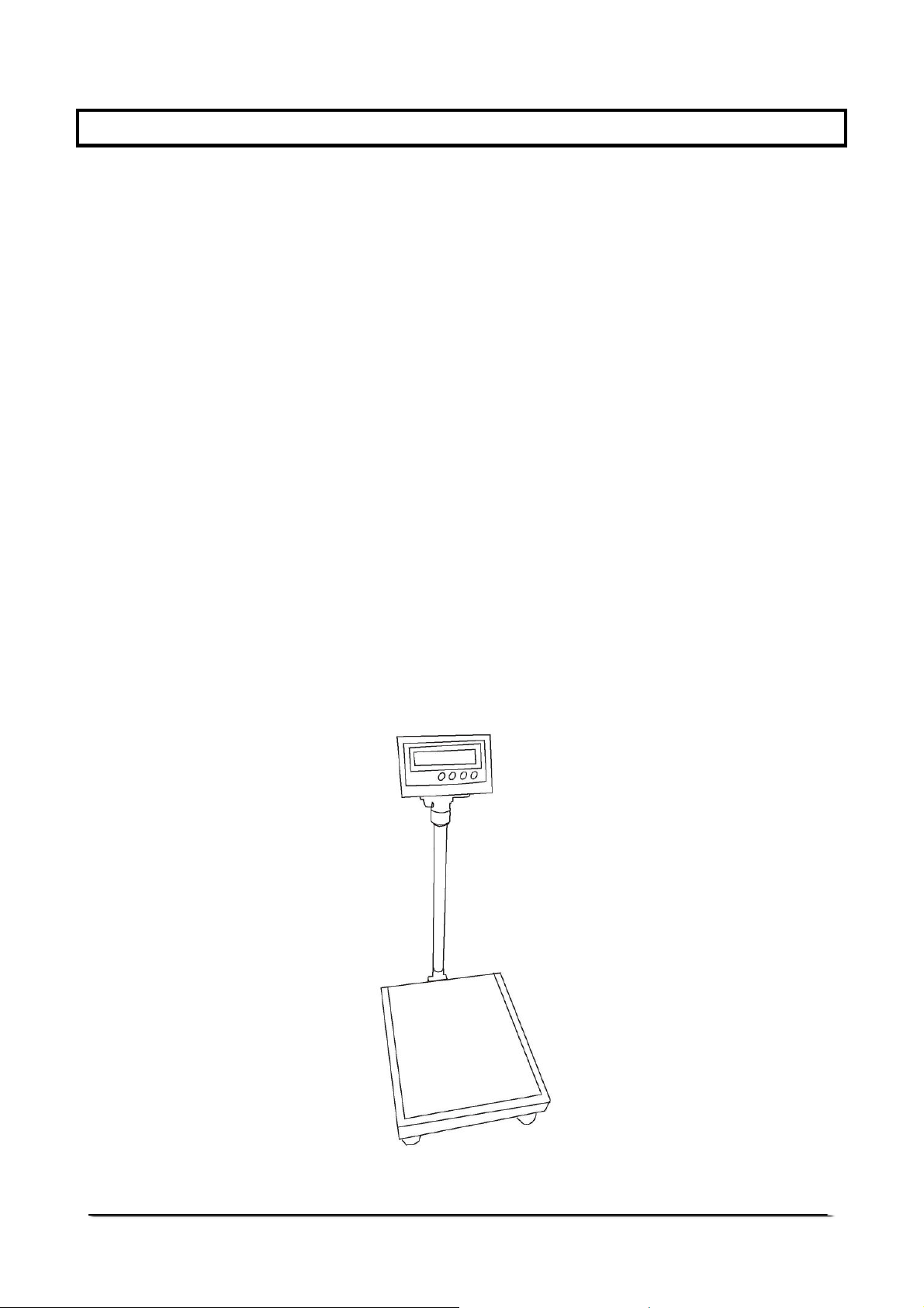
The BFW Platform Scales are the general purpose weighing scales. The
scales have large platform and are designed for industrial applications.
The main features are-
• Available in a range of capacities
• Single load-cell construction
• Overload protection
• Adjustable levelling feet
• Mild steel construction offering rugged structure
• Large stainless steel pan
• Supplied complete with AE 301 indicator
• Simple operation
• Zero Tracking
• Selectable automatic backlight
• Check-weighing with low and high limits
• Bi-directional RS-232 interface as standard
• Selectable communication mode
• Operation from internal rechargeable battery or mains power
• 4 weighing units (kg, g, ounce & pound)
© Adam Equipment Company 2007
2
Page 5
2.0 SPECIFICATIONS
Model BFW 75 BFW 150 BFW 300
Maximum Capacity
Readability 5 g 10 g 20 g
Repeatability
(Std. Dev.)
Linearity (±) 10 g 20 g 40 g
Tare Range Full range
Units of Measure 4 (kg, g, lb, oz)
Stabilisation Time 2-3 seconds
Operating
Temperature
Power supply Re-chargeable battery located inside the indicator
Display Large LCD with backlight
Calibration Automatic calibration
Scale Housing Indicator: ABS Plastic
Pan Size 560 x 470 mm
75 kg 150 kg 300 kg
5 g 10 g 20 g
0°C to 40°C
or mains power
Platform: Mild steel base and stainless steel pan
Dimensions
(w x d x h)
Net Weight 20 kg
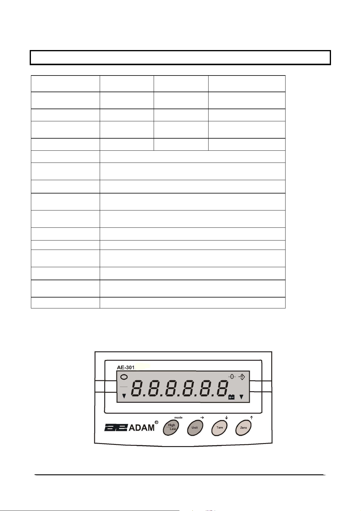
2.1 KEYBOARD AND DISPLAY
Base: 470 x 685 x 950 mm
Indicator : 260 x 155 x 105 mm
© Adam Equipment Company 2007
3
Page 6
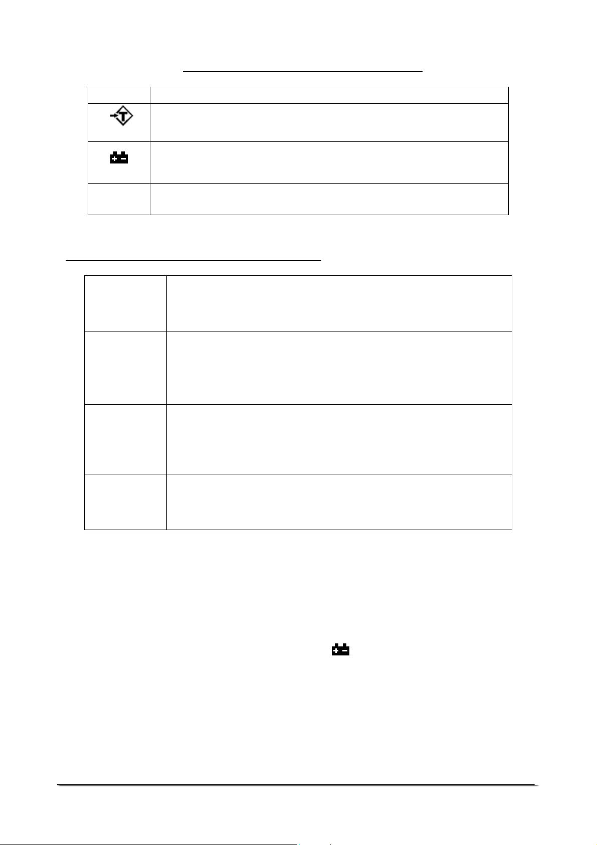
The display has the following symbols:
0
The battery needs to be re-charged. While the battery is getting
OOOO
The scale is at zero.
A weight has been tared, the display is showing the net weight.
re-charged, this symbol will be flashing.
The weight is stable.
The keys perform the following functions:
This key is used during setting of the user functions.
[High/Low/
Mode]
[Unit/]
It is also used during setting of the High and Low Limits for
check-weighing facility and for setting the alarm function.
This key is used to change the weighing units while the scale
is in the weighing mode.
It is also used for advancing the digit while the scale is in the
setting mode.
This key is used to deduct the weight of the container from the
gross weight and thus to display the net weight only.
[Tare/]
[Zero/ ]
It is also used to increment the digit while the scale is in the
setting mode.
This key is used to reset the zero position for accurate
weighing while the scale is in the weighing mode.
It is also used to decrease the digit during the setting mode.
2.2 POWER SUPPLY
• Power can be supplied using an internal re-chargeable battery
provided within the indicator case or the main power
• If the battery is low on charge, will be displayed. The battery
needs to be re-charged immediately. While the battery is getting
re-charged, this symbol will be flashing.
• With the internal re-chargeable acid battery, the battery life is
approximately 60 hours. The battery life will vary depending on
the use of the backlight.
© Adam Equipment Company 2007
4
Page 7

2.3 SETTING UP THE SCALE
Indicator
Cable with
Connector
Holder
Cable
Pillar
• Unpack the scale by removing from the box.
• Place the pillar in the upright position into the rear socket of the
platform base and fasten the screw.
• Pull out the cable slightly from the holder and slide the indicator
into the bracket.
• Attach the cable to the interface on the indicator to complete the
connection.
• Adjust the holder for the right position and fasten the fixed screw
on the display.
© Adam Equipment Company 2007
5
Page 8

3.0 OPERATIONS
3.1 POWER
• Attach the main power cord to the power supply. The indicator
will charge the internal battery whenever it is connected to the 220
VAC power supply.
• To turn on the scale, press the power switch on the right back of
the indicator.
• A message “
with a beep, ensuring all the segments are working. The message
“Uolt xx” will be shown before the display goes to zero. The value
of “xx” is an indication of the percentage of charge of the internal
battery.
SYS UP
SYS UP
SYS UPSYS UP
” will be displayed and then will run a self test
• To switch off the indicator press the power switch again.
3.2 ZERO FUNCTION
• For accurate weighing, zero the display by pressing the key
[Zero] with nothing on the platform of the scale.
• The zero indicator 0 will be on.
3.3 TARE FUNCTION
• When the scale has a container on it press the [Tare] key.
• The Tare indicator will be on.
• The display will show zero. If it does not show zero, press the
[Zero] key.
• To clear the tare, remove the container and press the [Tare] key
again. Press [Zero] to switch off the Tare indicator.
© Adam Equipment Company 2007
6
Page 9

3.4 UNIT SELECTION
• The indicator can be set for different units by pressing the [Unit]
key. The options are kilogram, gram, tonne, pound and ounce.
They can be enabled as needed (see section 6.2). Kilogram is
always on.
3.5 WEIGHING
• Place the sample on the scale platform. The weight will be
displayed in the selected Unit.
• Wait till the stable indicator is on for accurate weighing.
3.6 CHECK WEIGHING
Check-weighing is a procedure to sound an alarm when the weight of the
sample on the scale meets or exceeds the pre-set Low and High values
stored in memory, by using the [Mode] key.
To set the High and Low values, follow the procedure given below-
• Press the [Mode] key. The display will show “000.00 HI” with the
first digit flashing for setting the High value. Use the [Unit] key to
advance, the [Tare] key to change the value of the flashing digit.
Press [Mode] again to confirm the value.
• Press the [Mode] key again. The display will show “000.00 LOW”
with the first digit flashing for setting the High value. Use the
[Unit] key to advance, the [Tare] key to change the value of the
flashing digit. Press [Mode] again to confirm the value.
• Press [Mode] once again to return to normal weighing.
• Once the check weighing Limits are set and the alarm function is
active, a beep will sound slowly when the sample weight is below
the Low Limit. The beep will sound quickly if the weight is above
the High Limit. If the sample weight is in between the Limits, the
beep does not sound.
© Adam Equipment Company 2007
7
Page 10

3.7 ALARM
3.7.1 Over-load alarming
• When the sample weight on the scale is over the maximum capacity the
beep will sound and the display will show “EEE----“.
• Remove the weight immediately to avoid any damage to the scale.
3.7.2 Low-load alarming
• If the platform is not placed on the scale the beep will sound.
• Place the platform on the scale before starting to weigh.
3.7.3 Low battery alarming
• When appears on the LCD, re-charge the battery.
• During re-charging, the symbol will keep flashing and it will disappear
once the charging is complete.
• If this symbol appears along with the beep, stop using the scale at once
and re-charge the battery immediately to avoid any damage to the
battery.
4.0 USER PARAMETERS
The following parameters can be set by the user by entering the function
setting mode. Press the [Tare] key while switching on the indicator. The first
parameter will be displayed along with the settings done previously.
• The available parameters can be cycled through by pressing the
[Mode] key.
• Not all parameters may be enabled. Some parameters may be set
during the initial configuration and the user is not given access to
them. In this case those will not be seen when the [Mode] key is
pressed. To use any of the parameters see the corresponding
section of the manual.
• Switch off and switch on again to return to weighing.
© Adam Equipment Company 2007
8
Page 11

Parameters
Description
1.
2.
3.
4.
5.
6.
BLT
CHK
FIL
SDT
PAR
BPS
Enable / disable the backlight
Enable / disable the check-weighing facility
Enable / disable the ADC filter rate
Sets the RS-232 output function.
Options are 1, 2, 3 and 4.
Sets the following parity options-
8 n 1 7 E
E 1 -
E E
7 0
0 1 -
0 0
Changes the baud rate for RS-232 transmission
speed. Options are 1200, 2400, 4800 and 9600.
8 data bits, no parity
7 data bits, even parity
7 data bits, odd parity
4.1 BLT = BACKLIGHT CONTROL
• The backlight can be either enabled or disabled.
• When this function is displayed with the current setting, press the
[Unit] key to change to the other setting.
“bL= 0FF“ Backlight is disabled.
“bL= On” Backlight is enabled.
• Press the [Mode] key to store the desired setting and move to the
next function.
4.2 CHK = CHECKWEIGHING CONTROL
• When this function is displayed with the current setting, press the
[Unit] key to change to the other setting.
“CHK= 0FF“ Checkweighing is disabled.
“CHK= On” Checkweighing is enabled.
• Press the [Mode] key to store the desired setting and move to the
next function.
4.3 FIL = FILTERING CONTROL
• When this function is displayed with the current setting, press the
[Unit] key to change to the other setting.
“FIL= 0FF“ Filtering function is disabled.
“FIL= On” Filtering function is enabled.
© Adam Equipment Company 2007
9
Page 12

• Press the [Mode] key to store the desired setting and move to the
next function.
4.4 SDT = RS-232 CONTROL
• When this function is displayed with the current setting, press the
[Unit] key to change to the other settings.
1 Continuous output
2 Outputs under command from PC
3 Outputs weight when the scale is stable
4 Outputs complete data to printer when scale is stable
• Press the [Mode] key to store the desired setting and move to the
next function.
4.5 PAT = SETTING OF PARITY
• When this function is displayed with the current setting, press the
[Unit] key to change to the other settings.
8 n 1 - 8 data bits, no parity (default setting)
7 E
E 1 - 7 data bits, even parity
E E
7 0
0 1 - 7 data bits, odd parity
0 0
• Press the [Mode] key to store the desired setting and move to the
next function.
4.6 BPS = SELECTING BAUD RATE
• When this function is displayed with the current setting, press the
[Unit] key to change to the other settings. The options are 1200,
2400, 4800 and 9600 (default).
• Press the [Mode] key to store the desired setting.
• To return to weighing switch the scale off and then on again.
© Adam Equipment Company 2007
10
Page 13

6.0 RS-232 INTERFACE
The BFW series of scales come with a bi-directional RS-232 interface.
Default settings are 9600 baud, No Parity, 8 data bits, 1 stop bit (9600,N,8,1).
The standard Interface parameters are:
C
onnection details are:
RS-232 output of weighing data
ASCII code
Selectable Baud
Selectable data bits
Connector: 9 pin d-subminiature socket
Pin 2 Output
Pin 3 Input
Pin 5 Signal Ground
Selectable Parity
Normal OutputU: (For SDT 1, 2 and 3)
SN ± xxx.xxLL yy S stands for stable, U for unstable
N for net weight, G for gross weight,
LL for OK, HI or LO (during check weighing)
yy for the chosen unit( kg, g, lb, oz)
Complete Data Output: (For SDT 4)
When the SDT is set to 4 (see section 4.4), it will send 6 lines of data to the
printer in the following format
<SOH><cr><If>
G±sp spXXX.XXsp sp kg<cr><If>
T±sp spXXX.XXsp sp kg<cr><If>
N±sp spXXX.XXsp sp kg<cr><If>
<cr><If>
<cr><If>
<EOT>
First line is blank
Gross weight printed
Tare weight printed
Net weight printed
Blank line
Blank line
End of Transmission
Input command format:
The scale can be controlled from a PC with the following commands. The commands must
be sent in upper case letters, i.e. “T” not “t” and press the Enter button.
Command Description Scale will send back
N Sends the net weight to the
interface.
G Sends the gross weight to the
interface
T Sends the tare weight to the
interface.
Z Zero the scale. This is the same as
pressing [Tare] or [Zero].
Lxxx.xx Sets the lower limit. Same as
pressing the [High/Low].
Hxxx.xx Sets the upper limit. Same as
pressing the [High/Low].
C0 Disable check weighing.
SN ± xxx.xx yy or UN ± xxx.xx yy
SG ± xxx.xx yy or UG ± xxx.xx yy
ST ± xxx.xx yy or UT ± xxx.xx yy
Returns ERRH or ERRL if not in
weighing range
Returns ERRH or ERRL if not in
weighing range
© Adam Equipment Company 2007
11
Page 14

C1 Enable check weighing.
7.0 TECHNICAL PARAMETERS
To enter this section, press and hold the [Mode] and the [Tare] key while you
turn on the scale. The display will show the revision number and then the first
parameter Zero Tracking as “ZEO”
7.1 ZERO TRACKING
• When ZEO is displayed, press [Unit] to change to the other setting.
“ZEO= 0FF“ Zero tracking function is disabled.
“ZEO= On” Zer0 tracking function is enabled.
• Press the [Mode] key to store the desired setting and move to the
next function.
7.2 UNIT SETTING
The user will be able to enable the weighing units to be used - grams, pounds
or ounce. Kilogram is the default weighing unit.
• When g is displayed, press the [Unit] key to change to the other
setting.
“g= 0FF“ Gram unit is disabled.
“g= On” Gram unit is enabled.
• Press the [Mode] key to store the desired setting and move to the
next unit setting.
© Adam Equipment Company 2007
12
Page 15

7.3 CALIBRATION
Next is the Calibration section. “WEl” will be displayed.
• When WEI is displayed, press the [Unit] key to scroll through the
options for selecting the calibration mass.
• To select the desired mass press the [Mode] key.
• The raw ADC count will be displayed along with “CAI”.
• To set the zero calibration, press the [Mode] key again.
• The scale will ask you to load the calibration mass by displaying the
new ADC and “LOD”
• Place the calibration mass (same as the chosen “WEI” capacity) and
when the stable indicator is on, press [Mode] again.
• The display will show the value of the calibration mass.
• Remove the weight.
• The scale will return to the normal weighing.
© Adam Equipment Company 2007
13
Page 16

8.0 TROUBLE-SHOOTING GUIDE
PROBLEMS POSSIBLE CAUSES
Display is blank On/Off switch on rear panel is off
Scale not turned on
Battery not charged
No turn on test Battery not charged
Power supply not plugged in
Power supply faulty
Display turned off
Error message displayed - EEE Overload
Load cell damaged
Display is unstable Drafts or air currents
Load cell connections not secure
Obstruction under weighing platform
Vibrations through the floor
Temperature changed dramatically
Power supply faulty
Weight value incorrect Calibration error, Recalibrate
Unit calibrated with inaccurate weight
Obstruction around platform
Cannot use Full Capacity Overload stops hitting platform
support or hitting bottom of load cell
Parameters set incorrectly
Load cell Damaged
Not Linear Overload stops hitting too soon
Load cell damaged
Off Center Loading error
Battery will not charge Charging circuit failure
Overload stops not set correctly
Load cell damaged
Battery failure
Main voltage not present or too low
© Adam Equipment Company 2007
14
Page 17

9.0 SERVICE INFORMATION
A. Details of your company
This manual covers the details of operation. If you have a problem with the
scale that is not directly addressed by this manual then contact your supplier
for assistance. In order to provide further assistance, the supplier will need
the following information which should be kept ready:
-Name of your company:
-Contact person’s name:
-Contact telephone, e-mail,
fax or any other methods:
B. Details of the unit purchased
(This part of information should always be available for any future correspondence.
We suggest you to fill in this form as soon as the unit is received and keep a printout in your record for ready reference.)
Model name of the product:
BFW___
Serial number of the unit:
Software revision number
(Displayed when power is first turned on):
Date of Purchase:
Name of the supplier and place:
C. Brief description of the problem
Include any recent history of the unit. For example:
-Has it been working since it’s delivered
-Has it been in contact with water
-Damaged from a fire
-Electrical Storms in the area
-Dropped on the floor, etc.
© Adam Equipment Company 2007
15
Page 18

WARRANTY INFORMATION
Adam Equipment offers Limited Warranty (Parts and Labour) for the components
failed due to defects in materials or workmanship. Warranty starts from the date of
delivery.
During the warranty period, should any repairs be necessary, the purchaser must
inform its supplier or Adam Equipment Company. The company or its authorised
Technician reserves the right to repair or replace the components at any of its
workshops depending on the severity of the problems. However, any freight involved
in sending the faulty units or parts to the service centre should be borne by the
purchaser.
The warranty will cease to operate if the equipment is not returned in the original
packaging and with correct documentation for a claim to be processed. All claims are
at the sole discretion of Adam Equipment.
This warranty does not cover equipment where defects or poor performance is due to
misuse, accidental damage, exposure to radioactive or corrosive materials,
negligence, faulty installation, unauthorised modifications or attempted repair or
failure to observe the requirements and recommendations as given in this User
Manual.
Repairs carried out under the warranty does not extend the warranty period.
Components removed during the warranty repairs become the company property.
The statutory right of the purchaser is not affected by this warranty. The terms of this
warranty is governed by the UK law. For complete details on Warranty Information,
see the terms and conditions of sale available on our web-site.
© Adam Equipment Company 2007
16
Page 19

accordance with the instruction manual, may cause harmful interference to radio communications.
Manufacturer’s Declaration of Conformity
This product has been manufactured in accordance with the harmonised European standards,
following the provisions of the below stated directives:
Electro Magnetic Compatibility Directive 89/336/EEC
Low Voltage Directive 73/23/EEC
Adam Equipment Co. Ltd.
Bond Avenue, Denbigh East
Milton Keynes, MK1 1SW
United Kingdom
FCC COMPLIANCE
This equipment has been tested and found to comply with the limits for a Class A digital device,
pursuant to Part 15 of the FCC Rules. These limits are designed to provide reasonable protection
against harmful interference when the equipment is operated in a commercial environment. The
equipment generates, uses, and can radiate radio frequency energy and, if not installed and used in
Operation of this equipment in a residential area is likely to cause harmful interference in which case
the user will be required to correct the interference at his own expense.
Shielded interconnect cables must be employed with this equipment to insure compliance with the
pertinent RF emission limits governing this device.
Changes or modifications not expressly approved by Adam Equipment could void the user's
authority to operate the equipment.
WEEE COMPLIANCE
Any Electrical or Electronic Equipment (EEE) component or assembly of parts intended to be
incorporated into EEE devices as defined by European Directive 2002/95/EEC must be recycled or
disposed using techniques that do not introduce hazardous substances harmful to our health or the
environment as listed in Directive 2002/95/EC or amending legislation. Battery disposal in Landfill
Sites is more regulated since July 2002 by regulation 9 of the Landfill (England and Wales)
Regulations 2002 and Hazardous Waste Regulations 2005.
Battery
recycling has become topical
and the Waste Electrical and Electronic Equipment (WEEE) Regulations are set to impose targets
for recycling.
© Adam Equipment Company 2007
Page 20

ADAM EQUIPMENT is an ISO 9001:2000 certified global organisation with more than
30 years experience in the production and sale of electronic weighing equipment.
Products are sold through a world wide distributor network supported from our company
locations in the UK, USA, SOUTH AFRICA and AUSTRALIA.
ADAM’s products are predominantly designed for the Laboratory, Educational, Medical
and Industrial Segments. The product range is as follows:
-Analytical and Precision Laboratory Balances
-Counting Scales for Industrial and Warehouse applications
-Digital Weighing/Check-weighing Scales
-High performance Platform Scales with extensive software
features including parts counting, percent weighing etc.
-Crane scales for heavy-duty industrial weighing
-Digital Electronic Scales for Medical use
-Retail Scales for Price computing
Adam Equipment Co. Ltd.
Bond Avenue
Milton Keynes
MK1 1SW
UK
Tel:+44 (0)1908 274545
Fax: +44 (0)1908 641339
E-mail:
sales@adamequipment.co.uk
Adam Equipment Inc.
26, Commerce Drive
Tel: +1 203 790 4774
Fax: +1 203 792 3406
sales@adamequipment.com
Danbury, CT
06810
USA
E-mail:
Adam Equipment S.A. (Pty) Ltd.
7 Megawatt Road,
Spartan EXT 22, Kempton Park,
Johannesburg
Republic of South Africa
Tel: +27 (0)11 974 9745
Fax: +27 (0)11 392 2587
E-mail:
sales@adamequipment.co.za
Adam Equipment (S.E. ASIA)
2/71 Tacoma Circuit
Canning Vale, Perth
Tel: +61 (0) 8 6461 6236
Fax: +61 (0) 8 9456 4462
sales@adamequipment.au.com
© Copyright by Adam Equipment Co. Ltd. All rights reserved. No part of
this publication may be reprinted or translated in any form or by any means
without the prior permission of Adam Equipment.
Adam Equipment reserves the right to make changes to the technology,
features, specifications and design of the equipment without notice.
All information contained within this publication is to the best of our
knowledge timely, complete and accurate when issued. However, we are
not responsible for misinterpretations which may result from the reading of
this material.
The latest version of this publication can be found on our Website.
Visit us at www.adamequipment.com
Pty Ltd.
Western Australia
E-mail:
© Adam Equipment Company 2007
 Loading...