

ADA instruments Wall Scanner 80 User Manual
INSTRUMENTS
Operating manual
Wire, metal and wood detector
Model: Wall Scanner 80
Table of contents
1. Intended Use . . . . . . . . . . . . . . . . . . . . . . . . . . . . . . . . . . . . . . . . . . . . . . . . . 3
2. Product Features . . . . . . . . . . . . . . . . . . . . . . . . . . . . . . . . . . . . . . . . . . . . . . . . . . . . . 3
3. Technical data . . . . . . . . . . . . . . . . . . . . . . . . . . . . . . . . . . . . . . . . . . . . . . . . . . . . . . . 5
4. Detection performance . . . . . . . . . . . . . . . . . . . . . . . . . . . . . . . . . . . . . . . . . . . . . . . . . . . . . . . . . 6
5. Operation . . . . . . . . . . . . . . . . . . . . . . . . . . . . . . . . . . . . . . . . . . . . 6
6. Operating Instructions . . . . . . . . . . . . . . . . . . . . . . . . . . . . . . . . . . . . . . . . . . . . . 8
7. Maintenance and service . . . . . . . . . . . . . . . . . . . . . . . . . . . . . . . . . . . . . . . . . . . . . . . . . 9
8. Disposal . . . . . . . . . . . . . . . . . . . . . . . . . . . . . . . . . . . . . . . . . . . . . . . 9
9. Warranty. . . . . . . . . . . . . . . . . . . . . . . . . . . . . . . . . . . . . . . . . . . . . . 10
10. Exceptions from responsibility . . . . . . . . . . . . . . . . . . . . . . . . . . . . . . . . . . . . . . . . . . . . . . . . . . . . . . . 10
Appendix 1. Certicate of acceptance and sale
Appendix 2. Warranty card
2
MEASUREMENT FOUNDATION
INSTRUMENTSINSTRUMENTS
Intended Use
The measuring tool is intended for the detection of metals (ferrous and non-ferrous metals,
e.g., rebar), joists and ‘live’ wires/conductors
in walls, ceilings and oors.
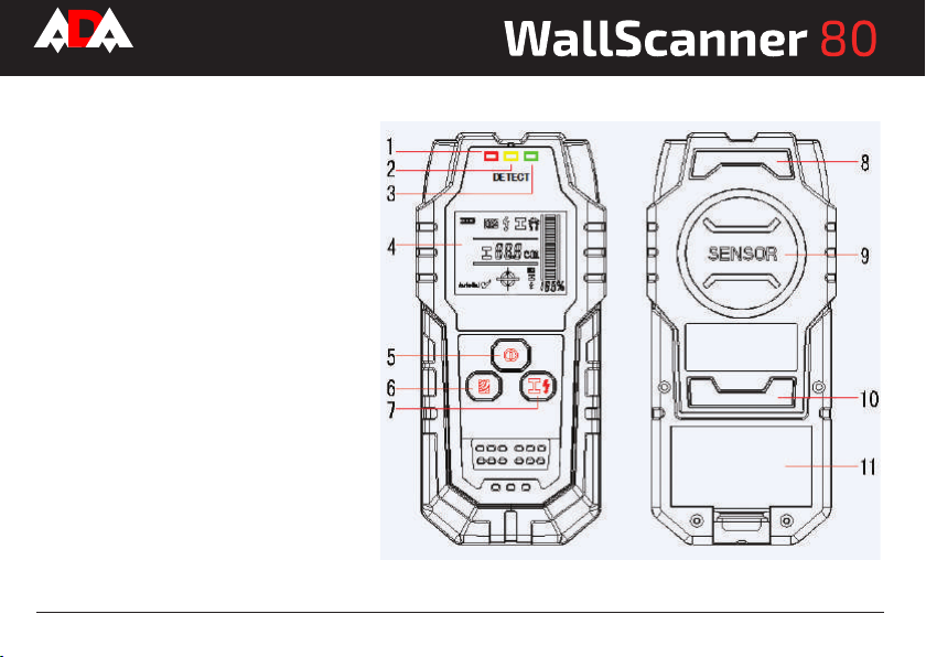
Product Features
1. Red light indicator
2. Yellow light indicator
3. Green light indicator
4. Display
5. ON/OFF button
6. Wood detection button
7. Metal/live wire detection button
8. Felt pad
9. Sensor area
10. Felt pad
11. Battery compartment
3
MEASUREMENT FOUNDATION
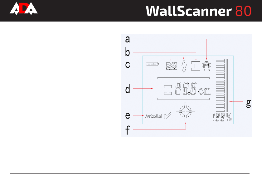
DISPLAY ELEMENTS
a) Indicator for magnetic/non-magnetic metals
b) Indicator for the current detection mode (wood,
live wire, metal)
c) Battery indicator
d) Indicator of metal depth detection
e) Indicator of “Autocal” calibration
f) Indicator of the detected object regarding the area
center (sensor area)
g) Signal strength
4
MEASUREMENT FOUNDATION

INSTRUMENTSINSTRUMENTS
Technical data
Maximum scanning depth*:
Ferrous metals 80 mm
Non-ferrous metals (Copper) 60 mm
Copper conductors(live)** 50 mm
Wood 20 mm
Automatic switch off after approx. 5 min
Operating temperature -10 °C…+50°C
Storage temperature -20°C…+70°C
Battery 1x9 V
Operating lifetime approx. 6 h
Weight 0.12 kg
*Depends on material and size of objects as material and condition of structure.
**Scanning depth will be smaller if wires/conductors are not “live”.
5
MEASUREMENT FOUNDATION
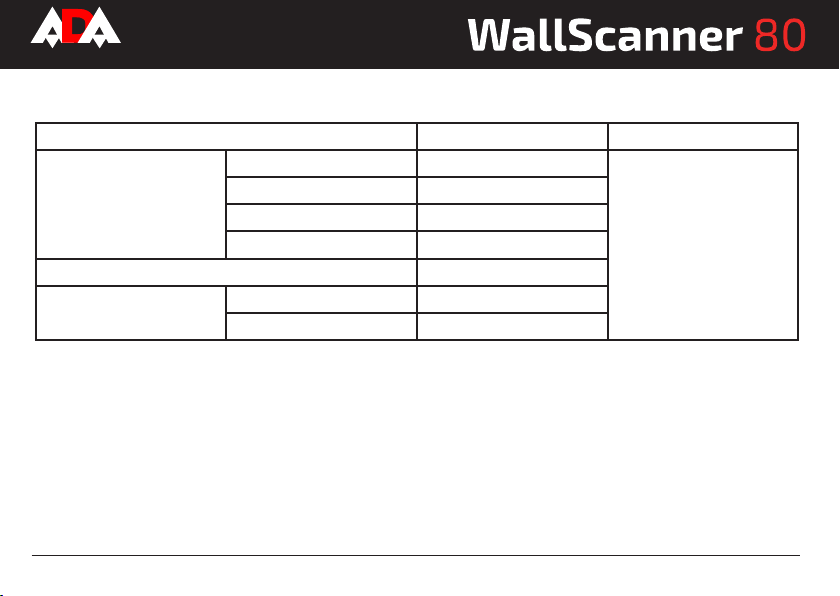
Detection performance
The object to be measured Depth of detection Accuracy of detection
Rebar/copper tube ø 20 8 cm/6 cm
ø 16 7 cm/6 cm
ø 12 6 cm/5 cm
ø 6 5 cm/5 cm
±1 cm
Live wire and cable 5 cm
Wood Wooden beam 2 cm
Wooden batten 2 cm
Operation
INSERTING/REPLACING THE BATTERY
Use only 9Vbattery. Insert the battery into the battery compartment (12) in accordance with the symbols in the battery compartment. Remove the batteries if the unit will not be used for a long period. The battery can be corroded or discharged over
long periods.
SWITCHING ON AND OFF
Protect the measuring tool against moisture and direct sun irradiation. Before switching the measuring tool on, make sure that
the sensor area 8 is dry. If required, wipe the measuring tool dry using a cloth.
6
MEASUREMENT FOUNDATION
INSTRUMENTSINSTRUMENTS
If the measuring tool was subject to an extreme temperature change, allow it to the adjust to the ambient temperature before
switching on. Press ON/OFF button to switch on the instrument. After a short test the detector is ready for operation. The
measuring tool automatically enter the function mode of metal detection. It is necessary to calibrate the instrument if you
hear sound alarm and see the red light indicator.
The calibration method is: place the instrument on nonmetallic surface or hold it in the hand away from any materials. Press the
metal button 7 until you hear sound alarm and green light is lit. Sound alarm and green light indicator show that the calibration
has been nished. Release button 7 to detect metal objects.
DETECTION OF OBJECTS
The detection of metal objects
Press button 7 to detect metal objects. Symbol b (the metal detection indicator) is indicated on the display and the green light is lit.
Place the measuring tool onto the surface to be scanned and move it sidewards, when the measuring tool comes close to a metal
object, the amplitude of the measuring indicator g increases. When it moves away from the object, the amplitude decreases, at the
position of maximum amplitude, the metal object is located below the center of the sensor. Indicator f is displayed on the display
and a steady tone sounds.
Indicator d (detection depth value) is displayed on the display when scanning metal objects. The accuracy of depth value is a
relation of shape and position of scanning metal objects. Symbol a shows whether metal is magnetic or not.
The detection of wooden objects
When scanning for wooden objects, the detector must come close to the wall. Then press the wood detection button 6. Don’t
move the instrument. Wait for the completion of calibration. When the calibration will be nished, you will see green light detector and there will be icon b (wood) on the display.
Place the measuring tool onto the surface and move around. When the detector come close to the wooden objects, the display
scale of g in the display will gradually increase. When the detector slowly moves away from object, the display scale will gradu-
7
MEASUREMENT FOUNDATION
ally decrease. A loud tone sounds when the instrument detects the object. If the object is located in the center of sensor area, the
icon f will appear on the display. The instrument makes a steady sound and the green light is lit.
Scanning for “live” wires
Press button 7 two times to activate “live” wires mode. The icon b appears on the display. Make the calibration if there is a sound
alarm, red light indicator and the instrument can’t detect the “live” wires.
Calibration: Place the instrument on nonmetallic surface or keep it in the hand far away from any materials. Press the metal
button 7 until you hear sound alarm and green light is lit. Sound alarm and green light indicator show that the calibration has
been nished. Release button 7 to detect metal objects.
The detector can detect 50 or 60 Hz (HZ) AC live power cables, other wires can only be indicated as metal objects.
Move the measuring tool over the surface repeatedly in order to determine the specic location of the live cables. After moving
the measuring tool over the surface several times, the detector is able to pinpoint the hiding place of “live” wires/conductor.
There is a red light indicator when the measuring tool is very close to the live wire. Signal tone sound with a rapid tone sequence. “Live”wires/conductors can be detected easier when power consumers (e.g., lamps, appliances) are connected to the
wire/conductor being sought and switched on. Wires/conductors with 110 V, 240V and 380 V (three-phase current) are detected
with about the same scan capacity.
Operating Instructions
In accordance with the principles of tool operation, the measuring values can be impaired through certain ambient
conditions. These include, e.g. the proximity of other equipment that produce strong magnetic or electromagnetic elds,
moisture, metallic building materials. Foil-laminated insulation materials or conductive wallpaper. Therefore, please
also observe other information sources (e.g. construction plans) before drilling, sawing or routing into walls, ceilings
or oors.
8
MEASUREMENT FOUNDATION

INSTRUMENTSINSTRUMENTS
Maintenance and service
Wipe away debris or contamination with a dry, soft cloth. Do not use cleaning agents or solvents. In order not to affect the
measuring function, decals/stickers or name plates, especially metal ones, may not be attached in the sensor area 8 on the
front or back side of the measuring tool. Do not remove the felt pads 7 on the back side of the measuring tool. Replace
the felt pads when then are damaged or used. For this, completely remove the felt pads and glue the new felt pads onto
the same spots. Store and transport the measuring tool only in the protective case.
Disposal
Measuring tools, accessories and packaging should be sorted for environmental-friendly recycling.
Only for EC countries:
Do not dispose of measuring tools into household waste! According the European Guideline 2002/96/EC for Waste
Electrical and Electronic Equipment and its implementation into national right, measuring tools that are no longer usable
must be collected separately and disposed of in an environmentally correct manner.
Battery packs/batteries: Do not dispose of battery pack/ batteries into household waste, re or water. Battery packs/
batteries should be collected, recycled or disposed of in an environmental-friendly manner.
Only for EC countries:
Defective or dead out battery packs/batteries must be recycled according the guideline 91/157/EEC.
9
MEASUREMENT FOUNDATION
 Loading...