

Page 1

Operating manual
Instrument of vertical projection
Model: ADA Vertical
Manufacturer
Address
.
Page 2

VERTICAL
Table of contents
1. Description and application . . . . . . . . . . . . . . . . . . . . . . . . . . . . . . . . . . . . . . . . . . . . . . . . . . . . . . . . . . . . . . . . . 3
2. Specications . . . . . . . . . . . . . . . . . . . . . . . . . . . . . . . . . . . . . . . . . . . . . . . . . . . . . . . . . . . . . 4
3. Construction features . . . . . . . . . . . . . . . . . . . . . . . . . . . . . . . . . . . . . . . . . . . . . . . . . . . . . . . . . . . 6
4. Preparation before operation. . . . . . . . . . . . . . . . . . . . . . . . . . . . . . . . . . . . . . . . . . . . . . . . . . . . . . . . . 7
5. Measurements. . . . . . . . . . . . . . . . . . . . . . . . . . . . . . . . . . . . . . . . . . . . . . . . . . . . . . . . . . . . . 9
6. Adjustment of the instrument . . . . . . . . . . . . . . . . . . . . . . . . . . . . . . . . . . . . . . . . . . . . . . . . . . . . . . . . . . . . . 9
7. Maintenance . . . . . . . . . . . . . . . . . . . . . . . . . . . . . . . . . . . . . . . . . . . . . . . . . . . . . . . . . . . . . . 11
8. Warranty . . . . . . . . . . . . . . . . . . . . . . . . . . . . . . . . . . . . . . . . . . . . . . . . . . . . . . . . . . . . . . . . 12
9. Exceptions from responsibility . . . . . . . . . . . . . . . . . . . . . . . . . . . . . . . . . . . . . . . . . . . . . . . . . . . . . . . . . . . . . . . 12
Appendix 1. Warranty card
Appendix 2. Certicate of acceptance and sale
Page 3

VERTICAL
ADA VERTICAL presents the instrument of vertical projection with laser emitter, class 2. Do not look into the laser beam
and do not aim at other persons.
1. Description and application
1) Transmission of planned position with the help of optical method or laser beam;
2) Bright visible red laser beam (635nm);
3) Brightness adjustment of laser beam;
4) Adjustment of diameter of laser spot to increase measurement accuracy;
5) Laser target with reticular division;
6) Bubble levels with LED backlight;
Laser beam is combined with axis of sight of telescope. Such alignment is very convenient when measuring. Because
it’s possible to make optical and laser measurements simultaneously. With the help of telescope it’s possible to control
the position of laser spot and transmit planned position of the dot in vertical direction.
Instrument of vertical projection is widely used by professionals for control when building elevator well, setting supports
for high-tension lines, building bridges and tunnels, skyscrapers, water towers, chimneys and for other works where it’s
necessary to have constant control.
Complete set
- instrument of vertical projection 1
- operating manual 1
- target plate 1
- lter 1
- calibrating pin 1
- case 1
- batteries 2
3
MEASUREMENT FOUNDATION
Page 4

2. Specications
Limit deviation of the plumb up ±2.0 мм/100м
Limit deviation of the plumb down ±1.0 мм/1.5м
Accuracy of tubular level 20” / 2 mm
Image inverted
Magnication 25х
Angle of view 1° 50’
Effective aperture of lens 36 mm
Shortest visual eld 0,8 m
Laser wavelength 635 nm
Optics and laser plumb (zenith)
Range of laser viewing 70 m
Laser range in the daytime<200m ; at night<250m
Laser power 5mW
Diameter of laser spot 3 mm / 50 m
Error of misalignmen of optical and
vertical axis is less than
Error of misalignmen of optical and
laser axis is less than
5”
5”
VERTICAL
4
MEASUREMENT FOUNDATION
Page 5

VERTICAL
Source Laser diod
Laser wavelength 650 nm
Laser plumb (down point)
Power supply 2 batteries type АА /1,5 V
Operating temperature -10° … + 45 °С
Continuous usage 8 h
Dimensions Ø 120х265
Weight 2,8 kg
Laser power 1mW
Effective laser range 2 m
Diameter of laser spot 1 mm / 1,5 m
Focusing range Not adjustable
5
MEASUREMENT FOUNDATION
Page 6

3. Construction features
VERTICAL
11
10
1
2
3
4
9
5
8
6
1) lens;
2) focusing screw;
3) battery compartment cover;
4) screw to switch on and brightness
adjustment;
5) screw to switch on and brightness
adjustment of laser plumb down;
6) eyepiece;
7) circular bubble level;
12
8) foot screws of the tribrach;
9) graduated limb;
10) focusing screw of the plumb down;
13
11) handle for transportation;
12) adjusting screw of tubular level;
13) tubular level
7
6
MEASUREMENT FOUNDATION
Page 7

VERTICAL
4. Preparation before operation
Insert the batteries
Remove battery compartment cover (3) and insert 2 batteries type AA observing the polarity.
Mounting the instrument on the tripod
Place the tripod on the construction site. Place the instrument on the tripod and tighten the central screw
properly. Adjust the height of the tripod for convenient operation with instrument. Adjust legs of the tripod,
so that the bubble of circular level (7) is exactly in the center of the level.
Leveling of the instrument
Coarse leveling with circle bubble:
1) Turn the foot screws A and B to enable the bubble of circular level (7) to position itself on the line that is
parallel to the line that goes through the foot screws A and B (pic.2).
2) Turn the foot screw C to enable bubble to position itself in the center of circular level (7) (pic.3).
Note: Circular bubble level is only used for leveling the instrument when mounting on the tripod. Leveling before measurements
is made with tubular level.
Pic.1
A
B
C
Pic.2 Pic.3
7
A
B
C
MEASUREMENT FOUNDATION
Page 8

VERTICAL
Fine adjustment with tubular level:
1) Turn the instrument in order to make the tubular level (13) parallel to the
line that goes through the foot screws A and B (pic.4);
2) Turn the foot screws A and B to make the bubble move into the middle
of tubular level (13);
3) Turn the instrument so that the tubular level (13) will be perpendicular
the line that goes through the foot screws A and B. Turn the foot screw C to
make the bubble move into the middle of tubular level (pic.5);
4) Repeat above described procedure only after turning the instrument, so
that the bubble will be in the center of tubular level.
Switch-on
1) Turn laser screw (5) to turn on laser dot of the marker of plumb down. Bright laser spot is projected on the target. Continue to
turn screw (5) to adjust the brightness of the laser spot;
2) Loosen central screw of the tripod. Move the instrument carefully on the tripod until the laser dot is on the reference point;
3) Repeat steps 4.3.2 for ne leveling of the instrument. Be sure, laser dot must be on the reference point.
Preparation before vertical measurements
Place laser target onto the place of the reference point. Turn screw (4) to switch on laser dot of the marker of plumb up. Rotate
focusing screw (2) to get accurate image of laser dot and marking on the laser target. If you need to increase the accuracy you
can use the method of the measurement of diameter:
1) Turn the graduated limb so that zero on the scale coincide with hairline on the housing of the instrument;
2) Mark up the position of laser dot;
3) Turn the instrument by 180° and mark up new position of laser dot;
Middle point between these two points is the reference point.
Pic.4 Pic.5
8
MEASUREMENT FOUNDATION
Page 9

VERTICAL
5. Measurements
Vertical measurements
1) Watch laser target and laser marker in the eyepiece of the instrument. If necessary, adjust sharpness of manual focusing;
2) Laser target can be moved vertically for transmission of reference point on desired height;
3) As a result you will get reference point. Line that connects these two points will be vertical.
Vertical measurements in wells
Such measurements can be used in mine survey and engineering surveying.
E.g. transfer of line (of given direction). As it is shown in the picture 6, lines A and B are known reference mark. Part of this line goes under well. There are two additional dots C and D on this line.
Transmission is made following way:
1) Place the instrument in the bottom of the well. Be sure, laser plumb (zenith) must coincide
with dot C;
2) Laser plumb down marks dot E, which will be the projection of dot C;
3) Do the same transmission of the dot D. Dot F is the projection of dot D;
4) If you connect dots E and F you will get line that is parallel AB.
6. Adjustment of the instrument
Adjustment of the tubular level
Axis of the level must be perpendicular to the rotation axis of the theodolite. Turn the alidade of the instrument, so that the axis
of tubular level will be parallel to the imaginary line, that connects centers of any 2 foot screws of the tribrach. Rotate these 2
screws in opposite directions, so that the bubble will be in the center of level. Rotate alidade of the instrument by 90° and with
the help of third screw place the bubble in the center.
Rotate alidade of the instrument by 90° once more. If necessary, place the bubble in the center of the level. Rotate alidade
A
C
D
F
E
Pic.6
B
9
MEASUREMENT FOUNDATION
Page 10

VERTICAL
of the instrument by 180°. It’s necessary to make further adjustment, if the offset of the bubble is more than 1 graduation. Half
of the value of bubble deviation is necessary to improve with the help of foot screws. Another half – with the help of adjustment
screw of tubular level.
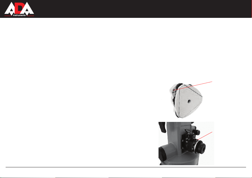
Adjustment of circle level
After adjustment of tubular level, it’s necessary to adjust circular level. If the bubble deviate from the center, adjust its position with
the help of three adjusting screws, which are located under the level (pic.7).
Adjustment of collimation error
Rotate the alidade by 180°, observing the center of croosshair of the target in
the lens. If you see the offset of the crosshair of reticule relatively the crosshair
of the target, it’s necessary to make adjustment:
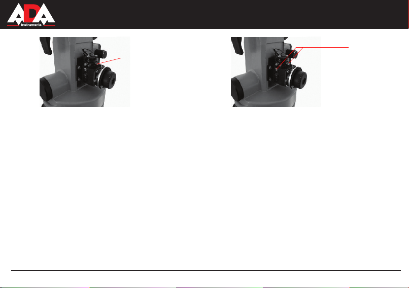
1) Place the instrument on the tripod or special stand;
2) Aim at the target at range 40 m outside and focus the image;
3) Turn the alidade of the instrument by 180°, observing the offset of reticule;
4) Adjust the position of reticule with the help of 4 adjusting screws, as shown in
the picture 8. Remove the offset by half;
5) Turn the alidade of the instrument by 180°. Repeat the adjustment by removing the offset completely.
Adjustment of the offset of laser beam
Collimation error between optical and laser axis occurs, If laser spot and the
center of reticule don’t coincide.
For adjustment :
1) Place the instrument on the tripod or special stand;
2) Aim at the target at range 40 m outside and focus the image;
10
Adjusting
screws of the
circle level
Pic.7
Adjusting
screws of the
reticule
Pic.8
MEASUREMENT FOUNDATION
Page 11

Adjusting
screw of
collimation
error
VERTICAL
Adjusting
screws of
laser spot
Pic.9
3) Rotate the adjusting screw, as shown in the picture 9 with the help of pin.
Laser spot must coincide with the center of reticule.
Adjustment of the focus of laser beam
Aim at the target and watch in the eyepiece. Rotate laser screw (4) until you get minimum size of the laser spot on the target.
Otherwise adjust the size of the laser spot up to the minimum size with the help of adjusting screws, as shown in the picture 10.
7. Maintenance
1) Use handle for transportation (11) to take the instrument from the box. Never touch the lens to take it from the case;
2) Rotation of the alidade must be easy;
3) Avoid direct sunlight during operation;
4) To clean the lens rst use special soft brush. Then wipe it with cotton wool or cleaning napkin. After usage remove all dust and
dirt from the surface of the instrument and place it into the clean dry case;
5) Keep the instrument clean;
6) Put the instrument into the case to avoid damages during transportation; Keep case in the dry clean place;
7) Insert out the batteries if you are not going to use instrument for a long time;
8) Don’t leave the instrument without usage for a long time on the construction site. Vibration, dust, humidity can have negative
inuence upon instrument.
11
MEASUREMENT FOUNDATION
Pic.10
Page 12

VERTICAL
Warranty
This product is warranted by the manufacturer to the original purchaser to be free from defects in material and workmanship under normal use for a period of two (2) years from the date of purchase.
During the warranty period, and upon proof of purchase, the product will be repaired or replaced (with the same or similar
model at manufactures option), without charge for either parts of labour.
In case of a defect please contact the dealer where you originally purchased this product. The warranty will not apply to
this product if it has been misused, abused or altered. Without limiting the foregoing, leakage of the battery, bending or
dropping the unit are presumed to be defects resulting from misuse or abuse.
Exceptions from responsibility
The user of this product is expected to follow the instructions given in operators’ manual.
Although all instruments left our warehouse in perfect condition and adjustment the user is expected to carry out periodic
checks of the product’s accuracy and general performance.
The manufacturer, or its representatives, assumes no responsibility of results of a faulty or intentional usage or misuse
including any direct, indirect, consequential damage, and loss of prots.
The manufacturer, or its representatives, assumes no responsibility for consequential damage, and loss of prots by any
disaster (earthquake, storm, ood ...), re, accident, or an act of a third party and/or a usage in other than usual condi-
tions.
The manufacturer, or its representatives, assumes no responsibility for any damage, and loss of prots due to a change of
data, loss of data and interruption of business etc., caused by using the product or an unusable product.
The manufacturer, or its representatives, assumes no responsibility for any damage, and loss of prots caused by usage
other thsn explained in the users’ manual.
The manufacturer, or its representatives, assumes no responsibility for damage caused by wrong movement or action due
to connecting with other products.
12
MEASUREMENT FOUNDATION
Page 13

WARRANTY DOESN’T EXTEND TO FOLLOWING CASES:
1. If the standard or serial product number will be changed, erased, removed or wil be unreadable.
2. Periodic maintenance, repair or changing parts as a result of their normal runout.
3. All adaptations and modications with the purpose of improvement and expansion of normal sphere of product application,
mentioned in the service instruction, without tentative written agreement of the expert provider.
4. Service by anyone other than an authorized service center.
5. Damage to products or parts caused by misuse, including, without limitation, misapplication or nrgligence of the terms of
service instruction.
6. Power supply units, chargers, accessories, wearing parts.
7. Products, damaged from mishandling, faulty adjustment, maintenance with low-quality and non-standard materials, pres-
ence of any liquids and foreign objects inside the product.
8. Acts of God and/or actions of third persons.
9. In case of unwarranted repair till the end of warranty period because of damages during the operation of the product, it’s
transportation and storing, warranty doesn’t resume.
For more information you can visit our website WWW.ADAINSTRUMENTS.COM
or write the letter with your questions on info@adainstruments.com
Page 14

WARRANTY CARD
Name and model of the product ________________________________________________
Serial number ________________date of sale_______________________
Name of commercial organization _____________________stamp of commercial organization
Warranty period for the instrument explotation is 24 months after the date of original retail purchase.
During this warranty period the owner of the product has the right for free repair of his instrument in case of manufacturing defects.
Warranty is valid only with original warranty card, fully and clear lled (stamp or mark of thr seller is obligatory).
Technical examination of instruments for fault identication which is under the warranty, is made only in the authorized service center.
In no event shall manufacturer be liable before the client for direct or consewuential damages, loss of prot or any other damage which
occur in the result of the instrument outage.
The product is received in the state of operability, without any visible damages, in full completeness. It is tested in my presence. I have no
complaints to the product quality. I am familiar with the conditions of qarranty service and i agree.
purchaser signature _______________________________
Before operating you should read service instruction!
If you have any questions about the warranty service and technical support contact seller of this product
Page 15

Certicate of acceptance and sale
__________________________________________________________________________
__________________________________________________________________________
___________________________________________________________№_____________
name and model of the instrument
Corresponds to ______________________________________________________________
designation of standard and technical requirements
Data of issue _______________________________________________________________
Stamp of quality control department
Price
Sold ___________________________________ Date of sale ______________________
name of commercial establishment
Page 16

MEASUREMENT FOUNDATION
WWW.ADAINSTRUMENTS.COM
ADA
Page 17
Руководство по эксплуатации
Прибор вертикального проектирования
Модель: ADA Vertical
Производитель: ADAINSTRUMENTS Адрес: WWW.ADAINSTRUMENTS.COM
Page 18

VERTICAL
Оглавление
1. Описание и предназначение прибора . . . . . . . . . . . . . . . . . . . . . . . . . . . . . . . . . . . . . . . . . . . . . . . . . . . . . . . 19
2. Основные технические параметры прибора . . . . . . . . . . . . . . . . . . . . . . . . . . . . . . . . . . . . . . . 20
3. Внешний вид и составляющие прибора . . . . . . . . . . . . . . . . . . . . . . . . . . . . . . . . . . . . . . . . . . . . . . . . . . . . . . . 22
4. Подготовка к работе . . . . . . . . . . . . . . . . . . . . . . . . . . . . . . . . . . . . . . . . . . . . . . . . . . . . . . . . . . 23
5. Измерения . . . . . . . . . . . . . . . . . . . . . . . . . . . . . . . . . . . . . . . . . . . . . . . . . 25
6. Регулировка прибора. . . . . . . . . . . . . . . . . . . . . . . . . . . . . . . . . . . . . . . . . . . . . . . . . . . . . . . . . . . . 26
7. Обслуживание прибора . . . . . . . . . . . . . . . . . . . . . . . . . . . . . . . . . . . . . . . . . . . . . . . . . . . . . . . . . . . . 28
8. Гарантия . . . . . . . . . . . . . . . . . . . . . . . . . . . . . . . . . . . . . . . . . . . . . . . . . . . . . . . . . . . . 29
9. Освобождение от ответственности . . . . . . . . . . . . . . . . . . . . . . . . . . . . . . . . . . . . . . . . . . . . . . . . . . . . . . . . . . . . 29
Приложение 1. Гарантийный талон
Приложение 2. Свидетельство о приемке и продаже
18
MEASUREMENT FOUNDATION
Page 19

VERTICAL
Искренне благодарим Вас за доверие к нашей продукции!
Перед использованием внимательно прочтите руководство по эксплуатации. Соблюдайте правила эксплуатации
для продления срока службы и обеспечения точности прибора и исправного состояния.
ADA VERTICAL представляет собой прибор вертикального проектирования с лазерным излучателем 2 класса.
Избегайте прямого попадания луча в глаза. Не направляйте лазерный луч на других людей.
1. Описание и предназначение прибора
1) Передача планового положения оптическим методом или при помощи лазерного луча;
2) Хорошо видимый лазерный луч красного цвета ( 635nm );
3) Регулируемая яркость лазерного луча;
4) Регулировка диаметра лазерного пятна для повышения точности измерений;
5) Лазерная мишень с сетчатым делением;
6) Пузырьковые уровни с светодиодной подсветкой;
В приборе лазерный луч совмещен с визирной осью зрительной трубы. Такое совмещение очень удобно при
проведении измерений, так как можно проводить одновременно оптические и лазерные измерения. Так же с
помощью оптической трубы можно контролировать положение лазерного пятна и передавать плановое положение
точки в направлении зенит.
Прибор вертикального проектирования широко используется профессионалами для контроля при строительстве
шахт лифтов, установки опор высоковольтных линий, строительстве мостов и туннелей, высотных зданий,
водонапорных башен, дымовых труб и для других работ, где необходим постоянный точный контроль.
Комплект поставки:
Прибор, инструкция по эксплуатации, лазерная мишень, фильтр для защиты глаз, батарея (2шт.), калибровочная
игла, кейс.
19
MEASUREMENT FOUNDATION
Page 20

2. Основные технические параметры прибора
Предельные отклонения отвеса зенит (вверх) ±2.0 мм/100м
Предельные отклонения отвеса надир (вниз) ±1.0 мм/1.5м
Точность цилиндрического уровня 20” / 2 мм
Изображение обратное
Увеличение 25х
Угол обзора 1° 50’
Диаметр объектива 36 мм
Минимальное фокусное расстояние 0,8 м
Длина волны лазера 635 нм
Оптика и лазерный отвес (зенит)
Дальность визуального наблюдения лазера
Дальность работы лазера днем<200м; ночью<250м
Мощность лазера 5 мВт
Диаметр лазерного пятна 3 мм / 50 м
Ошибка несовпадения оптической
оси с вертикальной осью менее
Ошибка несовпадения оптической
оси и лазерной осью менее
70 м
5”
5”
VERTICAL
20
MEASUREMENT FOUNDATION
Page 21

VERTICAL
Источник Лазерный диод
Длина волны 650 нм
Лазерный отвес (надир)
Источник питания 2 батареи типа АА /1,5 В
Диапазон рабочих температур -10° … + 45 °С
Время непрерывной работы 8 ч
Размеры Ø 120х265
Вес 2,8 кг
Мощность лазера 1 мВт
Эффективный диапазон лазера 2 м
Диаметр лазерного пятна 1 мм / 1,5 м
Диапазон фокусировки Не регулируемый
21
MEASUREMENT FOUNDATION
Page 22

3. Внешний вид и составляющие прибора
VERTICAL
11
10
1
2
3
4
9
5
8
6
7
22
1) объектив;
2) ручка фокусировки;
3) крышка батарейного отсека;
4) ручка для включения и
регулировки яркости лазерного
отвеса вверх;
5) ручка для включения и
регулировки яркости лазерного
отвеса вниз;
12
6) окуляр;
7) круглый пузырьковый уровень;
8) подъемные винты трегера;
13
9) оцифрованный лимб;
10) ручка фокусировки отвеса вниз;
11) ручка для переноски;
12) винт регулировки
цилиндрического уровня;
13) цилиндрический уровень.
MEASUREMENT FOUNDATION
Page 23

VERTICAL
4. Подготовка к работе
Установка батареи
Откройте крышку батарейного отсека (3) и разместите две батареи типа АА. При установке
обратите внимание на полярность батареи.
Установка на штатив
Установите штатив на стройплощадке. Разместите прибор на площадке штатива и закрепите
становым винтом. Отрегулируйте высоту штатива для комфортной работы с прибором.
Отрегулируйте вылет ножек штатива таким образом, чтобы пузырек воздуха круглого уровня (7)
находился максимально по центру (рис.1).
Выравнивание прибора
Грубое выравнивание по круглому уровню:
1) Вращая подъемные винты А и В, добейтесь того, чтобы пузырек воздуха в круглом уровне (7) расположился на линии,
параллельной линии, проходящей через подъемные винты А и В (рис. 2).
2) Поверните подъемный винт С так, чтобы пузырек воздуха в круглом уровне (7) расположился в центре (рис. 3).
Примечание: Круглый уровень используется только для выравнивания прибора при установке на штатив. Выравнивание
перед измерениями производится по цилиндрическому уровню.
A
B
Рис.2 Рис.3
C
23
A
B
C
MEASUREMENT FOUNDATION
Рис.1
Page 24

VERTICAL
Точное выравнивание по цилиндрическому уровню:
1) Поверните прибор так, чтобы цилиндрический уровень (13)
располагался параллельно линии, проходящей через подъемные
винты А и В (рис. 4);
2) Вращая подъемные винты А и В, добейтесь расположения пузырька
воздуха по центру цилиндрического уровня (13);
3) Поверните прибор так, чтобы цилиндрический уровень (13)
располагался перпендикулярно линии, проходящей через подъемные
винты А и В. Вращая подъемный винт С, добейтесь расположения
пузырька воздуха по центру цилиндрического уровня (рис. 5);
4) Повторите вышеуказанные шаги только после вращения прибора, чтобы пузырек воздуха располагался по центру
цилиндрического уровня.
Включение
1) Поверните ручку (5) для включения лазерной точки маркера отвеса вниз, при этом проецируется яркое пятно на цель.
Продолжайте вращать ручку (5), отрегулируйте яркость лазерного пятна;
2) Ослабьте становой винт штатива. Осторожно двигайте прибор на площадке штатива, пока лазерная точка не
совпадет с точкой отсчета;
3) Повторите шаг 4.3.2 для точного выравнивания прибора. При этом следите за совпадением лазерной точки с
точкой отсчета.
Подготовка к вертикальным измерениям
Разместите лазерную мишень в месте, куда должна быть перенесена точка отсчета. Поверните ручку (4) для
включения лазерной точки маркера отвеса вверх. Вращая ручку фокусировки (2), добейтесь четкого изображения
лазерной точки и разметки на лазерной мишени. Если необходимо повысить точность, то можно использовать
способ измерения диаметра.
Рис.4 Рис.5
24
MEASUREMENT FOUNDATION
Page 25

Для это необходимо выполнить следующее:
1) Выставите оцифрованный лимб так, чтобы ноль на шкале совпал с риской на корпусе прибора;
2) Отметьте положение лазерной точки;
3) Разверните прибор на 180°, а также отметьте новое положение лазерной точки;
5. Измерения
Вертикальные измерения
1) Наблюдайте лазерную мишень и лазерный маркер в окуляр прибора. При необходимости
настройте резкость ручкой фокусировки;
2) Лазерная мишень может быть перемещена вертикально для переноса отсчетной точки на
требуемую высоту.;
3) В результате вы получите перенесенную по вертикали точку отсчета. Линия, соединяющая
эти две точки, будет вертикальна.
Вертикальные измерения в колодцах, шахтах
Такие измерения могут понадобиться в маркшейдерском деле или инженерных изысканиях.
Например перенос линии (заданного направления). Как показано на рис.6, линия AB является
известным ориентиром. Часть этой линии проходит над шахтой. На этой линии назначены
две дополнительные точки C и D.
Перенос осуществляется следующим образом:
1) Установите прибор в нижней части шахты и добейтесь, чтобы лазерный отвес зенит
(вверх) совпал с точкой С;
2) Лазерный отвес надир (вниз) обозначит точку Е, которая будет являться проекцией точки С;
3) Тем же способом переносится точка D. Точка F является проекцией точки D;
4) Соединив точки E и F получится линия, параллельная АВ.
VERTICAL
A
C
D
F
E
Рис.6
B
25
MEASUREMENT FOUNDATION
Page 26
VERTICAL
6. Регулировка прибора
Регулировка цилиндрического уровня
Ось уровня должна быть перпендикулярна оси вращения теодолита. Поверните алидаду прибора так, чтобы ось
цилиндрического уровня была параллельна воображаемой линии, соединяющей центры любых двух подъемных
винтов трегера. Вращая только эти два винта в противоположные стороны, добейтесь, чтобы пузырек был в середине
ампулы. Поверните алидаду прибора на 90 градусов и при помощи третьего винта выведите пузырек на середину.
Поверните алидаду прибора еще раз на 90 градусов. Сделайте доводку пузырька на середину (если это необходимо).
Поверните алидаду прибора на 180 градусов. Если отклонение пузырька больше одного деления, то необходимо
выполнить дальнейшую юстировку. Половину величины смещения
пузырька необходимо исправить при помощи подъемных винтов, а
другую - с помощью юстировочного винта цилиндрического уровня.
Регулировка круглого уровня
После юстировки цилиндрического уровня, необходимо сразу
отрегулировать круглый уровень. Если пузырек круглого уровня
отклоняется от центра, отрегулируйте его положение при помощи
трех юстировочных винтов, которые располагаются под уровнем (рис.7).
Регулировка коллимационной погрешности
Наблюдая в объектив центр перекрестия мишени, вращайте
алидаду на 180°. Если при вращении наблюдается смещение
перекрестия нитей относительно перекрестия мишени, то
необходимо произвести настройку:
1) Установите прибор на штатив или специальный стенд;
2) Наведитесь на цель в 40 метрах снаружи и сфокусируйте
изображение;
26
MEASUREMENT FOUNDATION
Юстировочные
винты
круглого
уровня
Рис.7
Регулировочные
винты сетки
нитей
Рис.8
Page 27
VERTICAL
Регулировочный винт
коллимационной
ошибки
Рис.9
3) Поверните алидаду прибора на 180°, наблюдая за смещением сетки нитей;
4) Отрегулируйте положение нитей при помощи четырех регулировочных винтов, как на рис.8. Устраните смещение
наполовину;
5) Поверните алидаду прибора на 180° и повторите регулировку, устранив смещение полностью.
Регулировка отклонения лазерного луча
Если лазерное пятно и центр сетки нитей не совпадают, то это свидетельствует о коллимационной ошибке между
оптической и лазерной осями.
Для регулировки:
1) Установите прибор на штатив или специальный стенд;
2) Наведитесь на цель в 40 метрах снаружи и сфокусируйте изображение;
3) С помощью иглы вращайте регулировочный винт, как показано на рис.9. Добейтесь совпадения лазерного пятна
с центром сетки нитей.
Регулировка фокуса лазерного луча
Наведитесь на цель и наблюдайте в окуляр. Вращая ручку лазера (4), добейтесь минимального размера лазерного
пятна на мишени. В противном случае, при помощи двух регулировочных винтов, как показано на рис.10,
отрегулируйте размер лазерного пятна до минимального.
27
MEASUREMENT FOUNDATION
Винты
регулировки
размеров
лазерного
пятна
Рис.10
Page 28

VERTICAL
7. Обслуживание прибора
1) Извлечение прибора из кейса производите при помощи ручки для переноски (11). Ни в коем случае не извлекайте
прибор из кейса, потянув за объектив;
2) Вращение алидады прибора должно быть легким;
3) Следует избегать прямых солнечных лучей при использовании прибора;
4) Для чистки линзы объектива используйте сначала специальную мягкую кисточку, а затем аккуратно протрите
ватой или чистящей салфеткой. После использования удалите салфеткой всю пыль и грязь с поверхности прибора,
и затем поместите в чистый, сухой кейс;
5) Содержите прибор в чистоте;
6) При транспортировке укладывайте прибор в футляр во избежание резких ударов и толчков, которые могут
привести к повреждению и разъюстировке. Кейс с прибором должен храниться в сухом, чистом помещении;
7) Извлеките батареи из прибора при длительном хранении;
8) Не оставляйте прибор без надобности долго на стройплощадке. Вибрация, пыль, влага оказывает вредное
воздействие на прибор.
28
MEASUREMENT FOUNDATION
Page 29

VERTICAL
Гарантия
Производитель предоставляет гарантию на продукцию покупателю в случае дефектов материала или качества его
изготовления во время использования оборудования с соблюдением инструкции пользователя на срок до 2 лет со дня
покупки.
Во время гарантийного срока, при предъявлении доказательства покупки, прибор будет починен или заменен на такую
же или аналогичную модель бесплатно.
Гарантийные обязательства также распространяются и на запасные части.
В случае дефекта, пожалуйста, свяжитесь с дилером, у которого вы приобрели прибор.
Гарантия не распространяется на продукт, если повреждения возникли в результате деформации, неправильного
использования или ненадлежащего обращения.
Все вышеизложенные безо всяких ограничений причины, а также утечка батареи, искривление прибора являются
дефектами, которые возникли в результате неправильного использования или плохого обращения.
Освобождение от ответственности
Пользователю данного продукта необходимо следовать инструкциям, которые приведены в руководстве по
эксплуатации. Даже, несмотря на то, что все прборы проверены производителем, пользователь должен проверять
точность прибора и его работу.
Производитель или его представители не несут ответственности за прямые или косвенные убытки, упущенную
выгоду или иной ущерб, возникший в результате неправильного обращения с прибором. Производитель или
его представители не несут ответственности за косвенные убытки, упущенную выгоду, возникшие в результате
катастроф (землетрясение, шторм, наводнение и т.д.), пожара, несчастных случаев, действия третьих лиц и/или
использование прибора в необычных условиях. Производитель или его представители не несут ответственности
за косвенные убытки, упущенную выгоду, возникшие в результате изменения данных, потери данных и временной
приостановки бизнеса и т.д., вызванных применением прибора.
Производитель или его представители не несут ответственности за косвенные убытки, упущенную выгоду, возникшие
в результате использования прибора не по инструкции.
29
MEASUREMENT FOUNDATION
Page 30

ГАРАНТИЙНЫЕ ОБЯЗАТЕЛЬСТВА НЕ РАСПРОСТРАНЯЮТСЯ НА СЛЕДУЮЩИЕ СЛУЧАИ:
1.Если будет изменен, стерт, удален или будет неразборчив типовой или серийный номер на изделии;
2.Периодическое обслуживание и ремонт или замену запчастей в связи с их нормальным износом;
3.Любые адаптации и изменения с целью усовершенствования и расширения обычной сферы применения изделия,
указанной в инструкции по эксплуатации, без предварительного письменного соглашения специалиста поставщика;
4.Ремонт, произведенный не уполномоченным на то сервисным центром;
5.Ущерб в результате неправильной эксплуатации, включая, но не ограничиваясь этим, следующее: использование
изделия не по назначению или не в соответствии с инструкцией по эксплуатации на прибор;
6.На элементы питания, зарядные устройства, комплектующие, быстроизнашивающиеся и запасные части;
7. Изделия, поврежденные в результате небрежного отношения, неправильной регулировки, ненадлежащего
технического обслуживания с применением некачественных и нестандартных расходных материалов, попадания
жидкостей и посторонних предметов внутрь.
8.Воздействие факторов непреодолимой силы и/или действие третьих лиц;
9.В случае негарантийного ремонта прибора до окончания гарантийного срока, произошедшего по причине
полученных повреждений в ходе эксплуатации, транспортировки или хранения, и не возобновляется.
Для получения дополнительной информации Вы можете посетить наш Интернет сайт WWW.ADAINSTRUMENTS.COM
или написать письмо с интерисующими Вас вопросами на электронный адрес info@adainstruments.com
Page 31

ГАРАНТИЙНЫЙ ТАЛОН
Наименование изделия и модель _______________________________________________
Серийный номер ___________________Дата продажи_________________
Наименование торговой организации ___________________Штамп торговой организации мп.
Гарантийный срок эксплуатации приборов составляет 24 месяца со дня продажи.
В течении гарантийного срока владелец имеет право на бесплатный ремонт изделия по неисправностям,
являющимся следствием производственных дефектов.
Гарантийные обязательства действительны только по предъявлении оригинального талона, заполненного
полностью и четко (наличие печати и штампа с наименованием и формой собственности продавца
обязательно).
Техническое освидетельствование приборов (дефектация) на предмет установления гарантийного случая
производится только в авторизованной мастерской.
Производитель не несет ответственности перед клиентом за прямые или косвенные убытки, упущенную выгоду
или иной ущерб, возникшие в результате выхода из строя приобретенного оборудования.
Правовой основой настоящих гарантийных обязательств является действующее законодательство, в частности,
Федеральный закон РФ “О защите прав потребителя” и Гражданский кодекс РФ ч.II ст. 454-491.
Товар получен в исправном состоянии, без видимых повреждений, в полной комплектности, проверен в моем
присутствии, претензий по качеству товара не имею. С условиями гарантийного обслуживания ознакомлен и
согласен.
Подпись получателя_________________________________
Перед началом эксплуатации внимательно ознакомьтесь с инструкцией по эксплуатации!
По вопросам гарантийного обслуживания и технической поддержки обращаться к продавцу данного товара
Page 32

СВИДЕТЕЛЬСТВО О ПРИЕМКЕ И ПРОДАЖЕ
______________________________________________________________________________________________
______________________________________________________________________________________________
_____________________________________________________________________________№_______________
НАИМЕНОВАНИЕ И ТИП ПРИБОРА
Соответствует __________________________________________________________________________________
обозначение стандарта и технических условий
Дата выпуска ___________________________________________________________________________________
Штамп ОТК (клеймо приемщика)
Цена
Продан(а) ___________________________________________________Дата продажи ______________________
Page 33

Page 34

MEASUREMENT FOUNDATION
WWW.ADAINSTRUMENTS.COM
ADA
 Loading...