

Page 1
Schmidt Hammer 225
Operating manual
Test Hammer
Model: Schmidt Hammer 225
Manufacturer
Address: WWW. ADAINSTRUMENTS.COM
Page 2

Schmidt Hammer 225
Table of contents
1. Working principle . . . . . . . . . . . . . . . . . . . . . . . . . . . . . . . . . . . . . . . . . . . . . . . . . . . . . 3
2. Operational procedures . . . . . . . . . . . . . . . . . . . . . . . . . . . . . . . . . . . . . . . . . . . . . . . . . 7
3. Inspecting methods . . . . . . . . . . . . . . . . . . . . . . . . . . . . . . . . . . . . . . . . . . . . . . . . . . . .8
4. Calibration . . . . . . . . . . . . . . . . . . . . . . . . . . . . . . . . . . . . . . . . . . . . . . . . . . . . . . . . 9
5. Maintenance . . . . . . . . . . . . . . . . . . . . . . . . . . . . . . . . . . . . . . . . . . . . . . . . . . . . . . 10
6. Warranty . . . . . . . . . . . . . . . . . . . . . . . . . . . . . . . . . . . . . . . . . . . . . . . . . . . . . . . . . 12
7. Exceptions from responsibility . . . . . . . . . . . . . . . . . . . . . . . . . . . . . . . . . . . . . . . . . . . . . . . 12
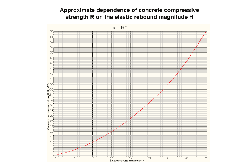
8. Appendix 1 - “Approximate dependence of conerete compressive strength R on the elastic rebound magnitude H”
9. Appendix 2 - “Classes, grades and concrete compressive strength communication with variation factor 13,5 %”
10. Warranty card
11. Certicate of acceptance and sale
Page 3

Schmidt Hammer 225
Working principle
Test hammer the stability of technical specication, reliability, consistency, rebound method for ensuring the accuracy of
testing the compressive strength of concrete is essential.
Therefore, the technical parameters and specication of test hammer should be standardized. Normal Impact energy is
2. 207N.m of concrete test hammer basic technical specication are as following:
Normal Impact energy: 2. 207N. m (0. 225kgf. m)
it is main design parameters of the instrument, when the test hammer rebound at level, bomb attack tension spring
stretch length 75mm which has the kinetic energy. Although it can’t directly test Hammer kinetic energy of the instruments, but, through controlling the stiffness and the standard tensile length of tension spring, and related precision of
the parts, may also be to control kinetic energy purposes.
Strike tension spring stiffness: 7.84N (0.80kgf) /cm.
Stiffness for tension spring will directly affect the nominal kinetic energy size of test hammer, usually through the spring
testing machine strict inspecting the technical parameters, but also can be inspect it according to “JJG817-93” standard
stated special spring testing device.
Strike hammer stroke: 75mm (Namely: strike tension spring stretched the
length of the standard).
Generally, depend on assembly and adjusting to ensure the technical requirements. Instrument self-test method: adjust
the bolt length out on the end cover, when the strike hammer shoot out (namely: unhook), the scale mark of pointer
slider and scale 100 mark of rebound value graduation scale is superposition, this time the length out for strike tension
spring should be 75mm.
Working length of strike tension spring: 61.5mm
3
MEASUREMENT FOUNDATION
Page 4

MEASUREMENT FOUNDATION
Schmidt Hammer 225
Namely: the length for strike hammer and rod instant of collision when strike tension spring is a free don’t stress state.
Maximum static friction force between pointer slider and shaft, the standard identied as 0.5-G.SN, pointer-axis does not
allow grease smear. With 0.1-1N’s dynamometer can inspect this requirement.
Rebound values calibrated on steel anvil of hardness as HRC60 ± 2 steel anvil should be Rm = 80 ± 2, the calibrated
should be divided into four directions or rotation at any angles.
Spherical radius exposed strike rod end is 25+1 mm, collisions end with strike hammer as ring plane. Whether Test
Hammer manufacturers, or Test Hammer during use must comply with the above technical requirements, if one does not
meet, then the Test Hammer or repair, or replacement of parts, at last, it should be calibrate on the steel anvil again, and
the rebound values calibrated should be Rm= 80 ± 2.
Nominal kinetic energy of Test Rebound in the following formula:
In formula:
1
2
E—Kinetic energy, J(N.m-kgf.m), 2. 207J-0.225kgf.m
К—Tension spring stiffness, N / m; (785N / m)
L—Tension spring standard stretching length, mm(75mm)
E = KL
2
4
Page 5

Schmidt Hammer 225
Rebound values.
As we all know, using rebound hammer inspecting strength of concrete components is actually detected the surface
hardness of concrete and use a special denition of rebound values to describe and characterization of concrete
hardness,
obtained the correlation curve and mathematical model between rebound values and concrete components strength by
testing methods.
Denition of rebound values.
The denition of rebound values by the following formula:
L'
L
R—Rebound values
L—Strike tension spring standard stretching length, mm(75mm)
L’—Rebound distance at rst after strike hammer and rod are impacted
2.10 Graduated Scale of rebound value.
According to Test Hammer working principle and denition, design a special scale —rebound value graduated scale. This
ruler’s scale line distribution and arrangement is as follows: Rebound value full scale for 100, from 10 to 100 degrees as
45 grid, each grid for the two rebound values, numbers scale line : 10-20-20... ...100, the actual length of 67.5mm, from
the zero line to 100 scale lines, a length of 70mm.
R = X100%
5
MEASUREMENT FOUNDATION
Page 6
MEASUREMENT FOUNDATION
Schmidt Hammer 225
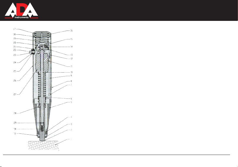
1. Test surface
2. Rebound pole
3. Dust felt ring
4. Semicircular clasp
5. Tension spring
6. Body B
7. Fixed block one
8. Calibration ruler
9. Pointer-axis
10. Center rod
11. Shrapel
13. Pointer slider
14. Hook spring
15. Fixed block two
16. End cover
17. Compression cover
18. Tighten nut
19. Adjustment bolt
20. Hook
21. Master lock
22. Positioning lock hook
23. Button nut
24. Button block
6
25. Button spring
26. Instrument shell
27. Rebound hammer
28. Spring circle
29. Buffer spring
30. Spring block
31. Cover cap
Page 7

Schmidt Hammer 225
Operational procedures of test hammer
Test hammer proper operation can improve the testing accuracy. Test hammer in operation throughout the entire process
should pay attention to hand holding instruments posture correct: namely, One hand hold the front part of the Test Hammer, the other hand hold and pressure the tail of end cover. The basic essentials of operation are: slowly and evenl with
the pushing press, vertical alignment measurement surface and no shaking.
Test hammer procedures are as follows:
1. Return zero
Test hammer strike rod withstand the concrete components surface, press tail cover lightly, positioning pins disengaged
hook-oriented ange; slowly lifting instrument, under the action of the compression spring, strike rod shots out, hook and
rebound hammer hung at the same time-oriented ange will be brought to zero pointer to the pointer slider, that red scale
line on the pointer slider overlap the zero line and Gauge.
2. Test Hammer action to obtain the energy
Would have been shot out of the strike rod targeting the surface of concrete component measuring point, even slowly
pushing and press Test Hammer, strike rod has been pressed into the Test Hammer, strike tension spring stretched; when
the instruments to push down to a certain location , hook back on oriented ange contact to the end of adjust bolt on back
cover and starts turn, to hook disengaged strike hammer monment, strike tension spring elongation up to the require
standard length 75mm, at this time has been nominal kinetic energy of 2.207Nm, rebound hammer in a hair-trigger state.
This operation process should be always maintained Test Hammer axis perpendicular to the inspecting surface, aviod
pushing and pressure force is too big and speed too fast.
7
MEASUREMENT FOUNDATION
Page 8

MEASUREMENT FOUNDATION
Schmidt Hammer 225
3. Rebound operation
Follow the operation abovp-mentioned and to continue pushing and press the Test Hammer until the rebound hammer
and hook was disengaged and under the stretched actoin of strike tension spring, strike hammer along the center guide
rod impact quickly, kinetic energy will decomposition of hammer and rod in the moment of collision : a part of the energy
to produce plastic deformation of concrete have been absorbed, the other part so that produces elastic deformation of
concrete transfer to sreike hammer to rebound.
Operation reading the rebound values
“ When the strike hammer and rod collision for the rst time rebound, will pointer slide into a certain position (through the
spring plate), then should continue to hold down the Test Hammer, and reading rebound values Ri from the slider scale
mark corresponding to the pointer ruler scale line ; if the inconvenience to reading, can press the button and lock the
machine, the movement to retain the slider pointer position, and then get the Test hammer to the place ease of reading
rebound values. The above is a rebound test operation process, which get the rebound value Ri of a measuring point,
Repeat the above operation will get the rebound value of measured points which needed.
Inspecting methods
Using Test Hammer inspect the compressive strength for structure or component of concrete which is base on measuring area as basic unit to carry out. This is that the structure or components divided into several measuring area, each
test area distribution of 16 measuring points, one measured area nished then test another, in the structure or structures
to orderly rebound inspect. Specic test method, see the appendix to this manual the industry standard “JGJ/T23-2001
<Technical Specication for Inspecting concrete compressive strength by Rebound Method> The new revision standard
of rebound method has a greater change, Wish our customers seriously and carefully read the standard, it is a guide to
the work of non-destructive testing.
The new revision standard of rebound method,changes are as belows:
1. Measurement strength curve range iiJ£-60MPa?)
2. Increased the calculation method for intensity conversion value of pumping concrete.
8
Page 9

Schmidt Hammer 225
3. Updated the concrete strength presumed method for single piece and batch inspecting.
Calibrate Test hammer
In order to ensure the Test Hammer reliability of technical performance and rebound method measurement accuracy
should be regular or irregular status of the instrument calibration. Calibration of test hammer divided into general and
periodic.
General calibration
Hammer commonly used frequently within effective certication period, the user as the case may be self-calibrate. The
standard self-calibrate devices at home and abroad are generally Hammer steel anvil at present For the Test Hammer
nominal kinetic energy < 2.207N. m, using GZ16 steel anvil Hammer machine technical status of a general self-calibrate
is entirely feasible.
Usually when the Test Hammer use frequently or has doubt for the instrument inspecting data, can calibrate on the steel
anvil, looked at the calibrating of rebound values Rm whether in the 8 0 + 2 or not . With only the calibration of steel anvil
Hammer rebound values to determine whether it is in normal is not complete. Operation must obtain the following procedure that test hammer’s state of technology compliance with standards and using requirements:
1. Check the maximum static friction force between pointer slider and shaft in the machine should be within the 0.5-0.8N,
if it does not meet the requirements to adjust.
2. Check the length of the effective work of strike tension spring is 61.5mm,
usually can adjust strike tension spring different holes location on spring seat to
meet the technical requirements.
3. Check the tension spring stretched standard length is 75mm. The technical parameter can be measured which instru-
ment should be work state, that is in the instrument to measure the length. Users inspecting the parameter is difcult to
measure under lack of detecting condition of Test Hammer.
9
MEASUREMENT FOUNDATION
Page 10

MEASUREMENT FOUNDATION
Schmidt Hammer 225
However, the movement can be taken to out of the instrument, and attchat a reversed margin, can be measured:
Take the strike hammer hang to hook, single-handedly stretched the spring out of the outer end face of rebound face, by
vernier caliper measured the distance between rebound hammer and the rebound rod collision face is76^3’0°mm.The
value is the standard-length 75 ± 0.3, with compression spring, strike tension spring superimposed on the deformation of
the buffer spring and make the amount of amendment).
4. After take the movement into instrument, check decoupling point, man pointer slide mark line in gauge line 100 overlap
and the rebound hammer decoupling, locking the nut of end cover then rotate and install it.
5. Take adjusted test hammer and calibrate on the steel anvil, if the calibrating rebound values Rm = 80 ±2, then the
instrument can be conrmed generally consistent with standard requirements, and can be put into ofcial uisng.
Generally, in the implementation of the above procedures before, shell Test Hammer Tear-down and cleaned all the parts
and components using gasoline or alcohol. After adjusting to right dimensions of assembly, wipe center guide rod using
cotton with the watches oil, to form a layer of thin oil lm, then the instrument for nal assembly , and nal calibration on
the steel anvil. By following the above procedures for debugging and inspecting, the test results with the Test Hammer of
the device achieved with the same effect.
Cycle Clibrating
According to”JJG817-93”standard on the Test Hammer detector to calibrate(omitted).
Maintenance
To improve the rebound method measuring strength accuracy, except the proper using and operating the instrument,
prociency testing technology, strict implementation of standards. That maintenance instrument frequently and makes
Test Hammer in good technical condition, which are indispensable for the proper use of equipment procedures.
Test Hammer should be disignated someone to use and custody.
After use of instrument should be wiped clean and take it into packaging or box.
Generally. Under should not be arbitrary demolition instrument or incorrect strike, absolutely can’t strike on the steel
plate, otherwise, which may cause irreversible damage to Test Hammer. Lest effect instrument’s using longevity and loss
of precisions.
10
Page 11

Schmidt Hammer 225
Test Hammer should be regularly maintained, general maintenance only needs to take out the movement, wipe the dirt
of collision surface between rebound hammer with pole and center guide rod, then wipe center guide rod to use cleaning
cotton with watches oil, and calibrating on steel anvil at last. Generally through these simple maintenances, Test Hammer will return to normal working condition. In particular heavy workload of test that makes general maintenance at any
time is very necessary. Generally pointer slider parts should not be demolished, within the calibration period, in the case
of the test hammer use frequently, for the movement part to clean, the rest can wipe with clean cotton yarn, that can
ensure that Test Hammer in normal technical condition. Test Hammer disassembly and installation procedures.
Rebound rod hit the ground lightly and press tail cover, make the button disengaged orientation ange, rebound rod shot
out.
Unscrew end cap and remove the compression spring, and unscrew front-end nut cap and semicircular clasp.
Test Hammer stands up which makes the movement upward, when the guide ange arrive at the top, hand-touch hook,
make hammer and hook disengaged, then,hold the hook by hand, take out the movements part.
Decomposition of movement, that can use the rebound hammer hit the rebound rod, make the rebound pole exit from
center guide rod and note that the buffer spring inside the rebound pole can’t lose. Will the Center guide rod take out
from the rebound hammer, thus complete the job for decomposition of movement. Guide ange and the center guide rod
has pasted rmly by 502 glue, generally open it is needless; FRL (rebound hammer, tension spring and spring seat) can
not be open arbitrarily too.
With the screwdriver rotate the Pointer-axis from the tail of instrument, spin to the pointer shaft separated from the pre-
xed block, with a small clamp to slicit pointer shaft, thus complete decomposition of Pointer Assembly.
When necessary, can use the screwdriver remove the rebound values graduate scale, the rule has 3 scales line: 0 scale,
100 decoupling calibration scale line and steel anvil calibration values scale line. Therefore, has no install
graduate scale can also be calibrated to the Test Hammer.
The above are procedures for demolition and decomposition of Test Hammer, on the contrary the process of assembly
and disassembly, demolition of part last that is installed rst. However, all parts tted to the instrument should be measured the size in prior, especially the two key dimensions on movement, working length of tension spring is 61.5+0.3mm,
standard tensile length is 76mm (measure from outside of instrument after revised).
11
MEASUREMENT FOUNDATION
Page 12

Schmidt Hammer 225
WARRANTY
This product is warranted by the manufacturer to the original purchaser to be free from defects in material and workmanship under normal use for a period of two (2) years from the date of purchase.
During the warranty period, and upon proof of purchase, the product will be repaired or replaced (with the same or similar model at manufactures option), without charge for either parts of labour.
In case of a defect please contact the dealer where you originally purchased this product. The warranty will not apply to
this product if it has been misused, abused or altered. Withiut limiting the foregoing, leakage of the battery, bending or
dropping the unit are presumed to be defects resulting from misuse or abuse.
EXCEPTIONS FROM RESPONSIBILITY
The user of this product is expected to follow the instructions given in operators’ manual.
Although all instruments left our warehouse in perfect condition and adjustment the user is expected to carry out periodic
checks of the product’s accuracy and general performance.
The manufacturer, or its representatives, assumes no responsibility of results of a faulty or intentional usage or misuse
including any direct, indirect, consequential damage, and loss of prots.
The manufacturer, or its representatives, assumes no responsibility for consequential damage, and loss of prots by any
disaster (earthquake, storm, ood ...), re, accident, or an act of a third party and/or a usage in other than usual condi-
tions.
The manufacturer, or its representatives, assumes no responsibility for any damage, and loss of prots due to a change
of data, loss of data and interruption of business etc., caused by using the product or an unusable product.
The manufacturer, or its representatives, assumes no responsibility for any damage, and loss of prots caused by usage
other thsn explained in the users’ manual.
The manufacturer, or its representatives, assumes no responsibility for damage caused by wrong movement or action
due to connecting with other products.
12
MEASUREMENT FOUNDATION
Page 13
Аppendix 1
Page 14

Page 15

Page 16

Аppendix 2
Page 17

WARRANTY DOESN’T EXTEND TO FOLLOWING CASES:
1. If the standard or serial product number will be changed, erased, removed or wil be unreadable.
2. Periodic maintenance, repair or changing parts as a result of their normal runout.
3. All adaptations and modications with the purpose of improvement and expansion of normal sphere of product application, mentioned in the service instruction, without tentative written agreement of the expert provider.
4. Service by anyone other than an authorized service center.
5. Damage to products or parts caused by misuse, including, without limitation, misapplication or nrgligence of the terms
of service instruction.
6. Power supply units, chargers, accessories, wearing parts.
7. Products, damaged from mishandling, faulty adjustment, maintenance with low-quality and non-standard materials,
presence of any liquids and foreign objects inside the product.
8. Acts of God and/or actions of third persons.
9. In case of unwarranted repair till the end of warranty period because of damages during the operation of the product,
it’s transportation and storing, warranty doesn’t resume.
For more information you can visit our website WWW.ADAINSTRUMENTS.COM
or write the letter with your questions on info@adainstruments.com
Page 18

WARRANTY CARD
Name and model of the product ________________________________________________
Serial number ________________date of sale_______________________
Name of commercial organization _____________________stamp of commercial organization
Warranty period for the instrument explotation is 24 months after the date of original retail purchase. It extends to the equipment, imported
on the RF territory by ofcial importer.
During this warranty period the owner of the product has the right for free repair of his instrument in case of manufacturing defects.
Warranty is valid only with original warranty card, fully and clear lled (stamp or mark of thr seller is obligatory).
Technical examination of instruments for fault identication which is under the warranty, is made only in the authorized service center.
In no event shall manufacturer be liable before the client for direct or consewuential damages, loss of prot or any other damage which
occur in the result of the instrument outage.
The product is received in the state of operability, without any visible damages, in full completeness. It is tested in my presence. I have no
complaints to the product quality. I am familiar with the conditions of qarranty service and i agree.
purchaser signature _______________________________
Before operating you should read service instruction!
If you have any questions about the warranty service and technical support contact seller of this product
Page 19

Certicate of acceptance and sale
__________________________________________________________________________
__________________________________________________________________________
___________________________________________________________№_____________
name and model of the instrument
Corresponds to ______________________________________________________________
designation of standard and technical requirements
Data of issue _______________________________________________________________
Stamp of quality control department
Price
Sold ___________________________________ Date of sale ______________________
name of commercial establishment
Page 20

Руководство по эксплуатации
Склерометр
Модель: Schmidt Hammer 225
Производитель: ADAINSTRUMENTS Адрес: WWW.ADAINSTRUMENTS.COM
Page 21

Schmidt Hammer 225
Оглавление
1. Назначение изделия . . . . . . . . . . . . . . . . . . . . . . . . . . . . . . . . . . . . . . . . . . . . . . . . . .22
2. Технические характеристики. . . . . . . . . . . . . . . . . . . . . . . . . . . . . . . . . . . . . . . . . . . . . 22
3. Комплектность. . . . . . . . . . . . . . . . . . . . . . . . . . . . . . . . . . . . . . . . . . . . . . . . . . . . . . . . .24
4. Устройство и принцип работы . . . . . . . . . . . . . . . . . . . . . . . . . . . . . . . . . . . . . . . . . . .
5. Меры безопасности. . . . . . . . . . . . . . . . . . . . . . . . . . . . . . . . . . . . . . . . . . . . . . . . . . 26
6. Подготовка изделия к работе . . . . . . . . . . . . . . . . . . . . . . . . . . . . . . . . . . . . . . . . . . . . . 26
7. Порядок работы. . . . . . . . . . . . . . . . . . . . . . . . . . . . . . . . . . . . . . . . . . . . . . . . . . . . . 27
8. Техническое обслуживание. . . . . . . . . . . . . . . . . . . . . . . . . . . . . . . . . . . . . . . . . . . . . . 28
9. Методика калибровки . . . . . . . . . . . . . . . . . . . . . . . . . . . . . . . . . . . . . . . . . . . . . . . . . 28
10. Протокол калибровки высоты отскока бойка и вариации показаний. . . . . . . . . . . . . . . . . . . . . . . 32
11. Гарантия . . . . . . . . . . . . . . . . . . . . . . . . . . . . . . . . . . . . . . . . . . . . . . . . . . . . . . . 34
12. Освобождение от ответственности . . . . . . . . . . . . . . . . . . . . . . . . . . . . . . . . . . . . . . . . . . 34
13. Приложение 1 - “Ориентировочная зависимость проточности бетона на сжатие R
от величины упругого отскока Н”
14. Приложение 2 - “Связь классов, марок и прочноти бетона на сжатие при коэффициенте вариации 13,5 %”
15. Гарантийный талон
16. Свидетельство о приемке и продаже
. .24
21
MEASUREMENT FOUNDATION
Page 22

MEASUREMENT FOUNDATION
Schmidt Hammer 225
Назначение изделия
Склерометр Schmidt Hammer 225 (в дальнейшем склерометр) предназначен для определения прочности бетона на
сжатие в диапазоне 10 - 60 МПа в бетонных и железобетонных конструкциях и изделиях методом упругого отскока
по ГОСТ 22690.
Принцип действия склерометра основан на ударе с нормированной энергией бойка о поверхность бетона и
измерении высоты его отскока (Н) в условных единицах шкалы прибора, являющейся косвенной характеристикой
прочности бетона на сжатие.
Прочность бетона определяют по градуировочным зависимостям между высотой отскока и прочностью бетона
на сжатие заранее установленным путем параллельных испытаний контрольных кубов бетона склерометром и в
прессе по ГОСТ 10180.
Склерометр является восстанавливаемым ремонтируемым изделием и может эксплуатироваться в закрытых
помещениях и на открытом воздухе.
Предельные значения климатических факторов:
при эксплуатации в температурном диапазоне от -5 до +40°С;
•
при хранении и транспортировании (в транспортной упаковке) в температурном диапазоне от -30 до +50°С.
•
Склерометр можно транспортировать любым видом транспорта и хранить, при защите от прямого попадания
капельной влаги на упаковочный футляр.
Технические характеристики
Склерометр позволяет проводить испытания бетона на прочность в контрольных бетонных кубах, бетонных и
железобетонных изделиях и конструкциях.
Высоту отскока измеряют в условных единицах шкалы склерометра.
22
Page 23

Schmidt Hammer 225
Энергия удара не менее 1,8 Дж.
Усилие сжатия пружины для
удара
Цена одного деления шкалы 2 условные единицы (в дальнейшем - усл. ед.)
Высота отскока бойка при
ударе на наковальне
Вариация показаний при
измерении высоты отскока на
контрольной наковальне
Твердость рабочих
поверхностей бойка и индентора
Шероховатость ударной части
индентора
Радиус сферы индентора (25±1) мм
Габаритные размеры
склерометра (длина, Ø max.)
Вес, кг. 1,3
не более 70 Н.
78 ±2 усл. ед. шкалы склерометра
±2 усл. ед. шкалы склерометра (одно деление)
не менее, 60 HRC
не более 10 мкм
280, 43
23
MEASUREMENT FOUNDATION
Page 24

MEASUREMENT FOUNDATION
Schmidt Hammer 225
Комплектность
Склерометр, упаковочный футляр, наждачный камень, руководство по эксплуатации.
Устройство и принцип работы
В корпусе склерометра, состоящем из цилиндрической 17, конической 18 частей (рис. 1), смонтированы
пружинный ударный механизм, содержащий съемный индентор 21, цангу 19, боек 5, держатель 10 с собачкой
15, рабочую 4, возвратную 13 и демпферную 20 пружины, и узел отсчета показаний склерометра в виде бегунка
6, который перемещается в пазе корпуса 17 вдоль шкалы 8 по скалке 7 и служит для фиксации высоты отскока
бойка.
Для фиксации положения держателя и одновременно бегунка после удара служит кнопка - стопор 16,
смонтированная в корпусе 17. Усилие фрикционного сопротивления перемещения бегунка 6 по скалке 7
регулируется за счет изменения степени поджатия боковых крыльев лепестка (рис. 2).
С внутренней стороны в крышку 12 ввинчен упорный болт 11, служащий для регулировки высоты удара бойка.
На передний торец конической части 18 корпуса навинчен колпачек 1, который при помощи двух полуколец
2 защемляет втулку 3, в которой проходит индентор 21, скользящий по цанге 19. На втулке имеется винтовая
канавка с отверстиями для крепления и регулировки натяжения переднего конца рабочей пружины 4, задний
конец которой закреплен на шейке бойка 5.
На передний конец цанги 19 насажен индентор 21, а на задний - навинчен держатель 10. На оси штифта 14,
установленного в держателе, закреплена собачка 15, служащая для захвата бойка при взводе склерометра.
Свободный конец собачки подпружинен.
24
Page 25

Рис.1
Schmidt Hammer 225
25
MEASUREMENT FOUNDATION
Page 26

MEASUREMENT FOUNDATION
Schmidt Hammer 225
Если кнопка не будет нажата, то после отвода корпуса от поверхности бетона держатель 10 вернет бегунок 6 в
исходное положение.
Для возврата склерометра в исходное положение (после удара, фиксации и считывания отсчета) необходимо
слегка нажать на сферический конец индентора. При этом держатель 10 сдвинется вверх, высвободится от
стопора 16, и под действием возвратной пружины 13 цанга 19 и индентор 21 будут перемещаться до тех пор, пока
собачка 15 не войдет снова в зацепление с бойком 5. При этом держатель 10 возвращает бегунок на нуль шкалы.
Указание мер безопасности
К работе со склерометром должны допускаться только лица, прошедшие обучение работе с ним в объеме
настоящего
руководства по эксплуатации и ГОСТ 22690.
Запрещается работать со склерометром с приставныхлестниц.
При эксплуатации и хранении избегать радиальных ударов по индентору. Транспортировать (переносить)
склерометр с индентором утопленным в корпус! Без необходимости - не разбирать!
Подготовка изделия к работе
Вынуть склерометр из транспортной тары.
Легким нажатием пальцем (ладонью) на сферический конец индентора 18 (рис.1) привести склерометр в исходное
положение. При этом бегунок 6 должен встать на нулевую отметку шкалы с погрешностью в две усл. ед. (одно
деление).
Провести пробный удар склерометром по наковальне. Для этого склерометр надо установить в гильзу наковальни,
прижать индентор к поверхности пуансона наковальни и плавно сдвинуть корпус к основанию наковальни до
щелчка (удара). Не отводя склерометр от поверхности пуансона наковальни, нажать пальцем на кнопку стопор 16,
26
Page 27

Schmidt Hammer 225
фиксируя положение бегунка после удара.
Вынуть склерометр из гильзы наковальни и определить по шкале высоту отскока с точностью до единицы (0,5
деления шкалы); она должна находиться в пределах, указанных в паспорте Сделать еще четыре удара. Во всех
случаях бегунок после снятия стопора должен возвращаться на нуль шкалы, а высота отскока находиться в
указанных в паспорте пределах.
Если указанные выше требования не выполняются необходимо провести проверку и регулировку в соответствии
с разд. 8 руководства по эксплуатации.
Порядок работы
Выбрать места испытания на изделии согласно указаниям ГОСТ 22690.
Привести склерометр в исходное положение.
Установить склерометр в выбранную точку испытуемой поверхности перпендикулярно к ней, следя, чтобы
отклонение от прямого угла не превышало 4 мм на высоту 100 мм. Удерживая склерометр за корпус двумя
руками так, чтобы один палец находился у стопора, нанести удар, определить
по шкале высоту отскока и зафиксировать ее в ведомости испытаний.
Продолжать испытания в других точках изделия.
Примечание 1. При испытании контрольных кубов бетона они должны быть зажаты в прессе согласно ГОСТ
22690.
Примечание 2. Положение склерометра относительно испытуемой поверхности должно быть таким же, как и при
установлении градуировочной зависимости, т.е. горизонтальным При необходимости испытания горизонтальных
или наклонных поверхностей следует зафиксировать угол наклона между продольной осью прибора и
горизонтальной плоскостью для введения поправки при обработке результатов.
27
MEASUREMENT FOUNDATION
Page 28

MEASUREMENT FOUNDATION
Schmidt Hammer 225
Техническое обслуживание
Склерометр обслуживается в авторизованном производителем сервисном центре.
Техническое обслуживание выполняют после длительного пользования (20000 ударов), но не реже, чем раз в
полгода перед началом работ.
Методика калибровки
Склерометр калибруют по МК РСК 003-004-97 или по ниже следующей методике.
Операции и средства калибровки.
При проведении калибровки должны быть выполнены
операции и применены средства поверки с характеристиками указанными в таблице:
28
Page 29

Schmidt Hammer 225
Наименование Наименование образцового средства измерения
операции и вспомогательного инструмента; номер документа,
регламентирующего технические требования к
средству, его основные технические характеристики
Внешний осмотр
Определение мет- Контрольная наковальня 48.00.000 ТУ
рологических харак
теристик
Определение высоты Пресс гидравлический/ сжатие на 500 кН по ГОСТ
отскока бойка
на наковальне
Определение
вариации показаний
при измерении
высоты отскока
Первичную калибровку следует проводить при выпуске склерометров из производства. Периодическую калибровку
следует проводить не реже одного раза в год и после ремонта.
Требования к квалификации персонала.
29
MEASUREMENT FOUNDATION
Page 30

MEASUREMENT FOUNDATION
Schmidt Hammer 225
К проведению калибровки допускают лиц, имеющих соответствующую квалификацию в соответствии.
Условия калибровки:
При проведении калибровки должны быть соблюдены нормальные условия: температура окружающего воздуха
(20±2)° С, влажность (не более 80) %.
Проведение калибровки.
Внешний осмотр.
При внешнем осмотре должно быть установлено наличие маркировки и отсутствие внешних повреждений,
влияющих на работу склерометра.
Заводской номер заносят в протокол калибровки.
При невыполнении требований калибровку не проводят.
Определение метрологических характеристик.
Склерометр вставляют в гильзу наковальни и производят 10 ударов по методике; определяют высоту
отскока Нi по шкале и записывают показания в протокол калибровки.
По результатам единичных измерений Нi вычисляют среднее арифметическое значение Н:
∑ Hi
H =
10
и разность Δ0 между средним значением Н и номинальным Н0, которое указано в Р.Э. на калибруемый
склерометр:
Δ0 = |Н-Н0|
Значение Н должно быть в пределах (±2) усл. ед., а разность показаний Δ0 - не превышать двух усл. ед.
Вычисляют разности Δi между средним значением Н и единичным Hi:
30
Page 31

Schmidt Hammer 225
Разности показаний Δi не должны превышать двух усл. ед.
Склерометры, прошедшие калибровку с отрицательным результатом, к применению не допускаются, их
направляют в ремонт и дают заключение об изъятии их из обращения.
31
MEASUREMENT FOUNDATION
Page 32

MEASUREMENT FOUNDATION
Schmidt Hammer 225
Определение высоты отскока бойка и вариации показаний
склерометра Schmidt Hammer 225 №_______________________________________________при испытании на
наковальне №_________________________________________________________________________________
Н0_______________________________________________________________________условных единиц шкалы.
Измерение Высота отскока, усл. ед.
1
2
3
4
5
6
7
Протокол калибровки высоты отскока бойка и вариации показаний
Разности, усл.ед.
при измерении Нi среднее Н
32
Δ0 = |Н-Н0| Δi = |Н-Нi|
Page 33

Schmidt Hammer 225Schmidt Hammer 225
8
9
10
Заключение: Склерометр Schmidt Hammer 225 №____________ соответствует требованиям.
Калибровку провел
_____ ________________201__г. ________________________ (______________________)
33
MEASUREMENT FOUNDATION
Page 34

MEASUREMENT FOUNDATION
Schmidt Hammer 225
Schmidt Hammer 225
Гарантия
Производитель предоставляет гарантию на продукцию покупателю в случае дефектов материала или качества его
изготовления во время использования оборудования с соблюдением инструкции пользователя на срок до 1 года со
дня покупки. Во время гарантийного срока, при предъявлении доказательства покупки, прибор будет починен или
заменен на такую же или аналогичную модель бесплатно. Гарантийные обязательства также распространяются и
на запасные части.
В случае дефекта, пожалуйста, свяжитесь с дилером, у которого вы приобрели прибор. Гарантия не
распространяется на продукт, если повреждения возникли в результате деформации, неправильного
использования или ненадлежащего обращения.
Все вышеизложенные безо всяких ограничений причины, а также утечка батареи, деформация прибора являются
дефектами, которые возникли в результате неправильного использования или плохого обращения.
Освобождение от ответственности
Пользователю данного продукта необходимо следовать инструкциям, которые приведены в руководстве по
эксплуатации. Даже, несмотря на то, что все прборы проверены производителем, пользователь должен проверять
точность прибора и его работу.
Производитель или его представители не несут ответственности за прямые или косвенные убытки, упущенную
выгоду или иной ущерб, возникший в результате неправильного обращения с прибором.
Производитель или его представители не несут ответственности за косвенные убытки, упущенную выгоду,
возникшие в результате катастроф (землетрясение, шторм, наводнение и т.д.), пожара, несчастных случаев,
действия третьих лиц и/или использование прибора в необычных условиях.
Производитель или его представители не несут ответственности за косвенные убытки, упущенную выгоду,
возникшие в результате изменения данных, потери данных и временной приостановки бизнеса и т.д., вызванных
применением прибора.
Производитель или его представители не несут ответственности за косвенные убытки, упущенную выгоду,
возникшие в результате использования прибора не по инструкции.
34
Page 35

Приложение 1
Page 36

Page 37

Page 38

Приложение 2
Page 39

ГАРАНТИЙНЫЕ ОБЯЗАТЕЛЬСТВА НЕ РАСПРОСТРАНЯЮТСЯ НА СЛЕДУЮЩИЕ СЛУЧАИ:
1.Если будет изменен, стерт, удален или будет неразборчив типовой или серийный номер на изделии;
2.Периодическое обслуживание и ремонт или замену запчастей в связи с их нормальным износом;
3.Любые адаптации и изменения с целью усовершенствования и расширения обычной сферы применения
изделия, указанной в инструкции по эксплуатации, без предварительного письменного соглашения специалиста
поставщика;
4.Ремонт, произведенный не уполномоченным на то сервисным центром;
5.Ущерб в результате неправильной эксплуатации, включая, но не ограничиваясь этим, следующее:
использовнаие изделия не по назначению или не в соответствии с инструкцией по эксплуатации на прибор;
6.На элементы питания, зарядные устройства, комплектующие, быстроизнашивающиеся и запасные части;
7. Изделия, поврежденные в результате небрежного отношения, неправильной регулировки, ненадлежащего
технического обслуживания с применением некачественных и нестандартных расходных материалов, попадания
жидкостей и посторонних предметов внутрь.
8.Воздействие факторов непреодолимой силы и/или действие третьих лиц;
9.В случае негарантийного ремонта прибора до окончания гарантийного срока, произошедшего по причине
полученных повреждений в ходе эксплуатации, транспортировки или хранения, и не возобновляется.
Для получения дополнительной информации Вы можете посетить наш Интернет сайт WWW.ADAINSTRUMENTS.COM
или написать письмо с интерисующими Вас вопросами на электронный адрес info@adainstruments.com
Page 40

ГАРАНТИЙНЫЙ ТАЛОН
Наименование изделия и модель _______________________________________________
Серийный номер ___________________Дата продажи_________________
Наименование торговой организации ___________________Штамп торговой организации мп.
Гарантийный срок эксплуатации приборов составляет 24 месяца со дня продажи и распространяется на
оборудование, ввезенное на территорию РФ официальным импортером.
В течении гарантийного срока владелец имеет право на бесплатный ремонт изделия по неисправностям,
являющимся следствием производственных дефектов.
Гарантийные обязательства действительны только по предъявлении оригинального талона, заполненного
полностью и четко (наличие печати и штампа с наименованием и формой собственности продавца
обязательно).
Техническое освидетельствование приборов (дефектация) на предмет установления гарантийного случая
производится только в авторизованной мастерской.
Производитель не несет ответственности перед клиентом за прямые или косвенные убытки, упущенную выгоду
или иной ущерб, возникшие в результате выхода из строя приобретенного оборудования.
Правовой основой настоящих гарантийных обязательств является действующее законодательство, в частности,
Федеральный закон РФ “О защите прав потребителя” и Гражданский кодекс РФ ч.II ст. 454-491.
Товар получен в исправном состоянии, без видимых повреждений, в полной комплектности, проверен в моем
присутствии, претензий по качеству товара не имею. С условиями гарантийного обслуживания ознакомлен и
согласен.
Подпись получателя_________________________________
Перед началом эксплуатации внимательно ознакомьтесь с инструкцией по эксплуатации!
По вопросам гарантийного обслуживания и технической поддержки обращаться к продавцу данного товара
Page 41

СВИДЕТЕЛЬСТВО О ПРИЕМКЕ И ПРОДАЖЕ
______________________________________________________________________________________________
______________________________________________________________________________________________
_____________________________________________________________________________№_______________
НАИМЕНОВАНИЕ И ТИП ПРИБОРА
Соответствует __________________________________________________________________________________
обозначение стандарта и технических условий
Дата выпуска ___________________________________________________________________________________
Штамп ОТК (клеймо приемщика)
Цена
Продан(а) ___________________________________________________Дата продажи ______________________
Page 42

MEASUREMENT FOUNDATION
WWW.ADAINSTRUMENTS.COM
ADA
 Loading...