

Page 1

MEASUREMENT FOUNDATION
Operating manual
Optical theodolite
Model
Manufacturer: ADAINSTRUMENTS Address:WWW.ADAINSTRUMENTS.COM
PROF X2
:
Page 2

Contents
ENG
1.
Review
. . . . . . . . . . . . . . . . . . . . . . . . . . . . . . . . . . . . . . . . . . . . . . . . 3
2.
Technical parameters
. . . . . . . . . . . . . . . . . . . . . . . . . . . . . . . . . . . . . . . . . 3
3.
Complete set
. . . . . . . . . . . . . . . . . . . . . . . . . . . . . . . . . . . . . . . . . . . . . 4
4.
Construction features
. . . . . . . . . . . . . . . . . . . . . . . . . . . . . . . . . . . . . . . . . 6
5.
How to use the instrument
. . . . . . . . . . . . . . . . . . . . . . . . . . . . . . . . . . . . . . 8
6.
Adjusting the instrument
. . . . . . . . . . . . . . . . . . . . . . . . . . . . . . . . . . . . . . . 11
7.
Precautions
. . . . . . . . . . . . . . . . . . . . . . . . . . . . . . . . . . . . . . . . . . . . . . 14
8. Warranty . . . . . . . . . . . . . . . . . . . . . . . . . . . . . . . . . . . . . . . . . . . . . . . 15
9. Exceptions From Responsibility . . . . . . . . . . . . . . . . . . . . . . . . . . . . . . . . . . . 15
10.
Attachement 1- “Certificate of acceptance and sale”
11.
Attachement 2- “Warranty card”
PROF X2
Page 3

MEASUREMENT FOUNDATION
1. REVIEW
2. TECHNICAL PARAMETERS
Telescope:
- Image formation positive
- Magnification 30х
- Effective aperture of lens 40 mm
- Angle of visual field 1° 30'
- Shortest visual range 2 m
- Stadia multiplication constant 100
- Stadia addition constant 0
- Length 172 mm
Spirit level:
- Tubular level of the alidade 30” / 2 mm
- Circular level 8' / 2 mm
Prof X2 are optical theodolites of medium precision. These instruments are easy to use.
Theodolites Prof X2 are used in national defence construction, geodesy and project surveying. They are mainly used in
the mapping of vast scale relief-maps and doing survey. It is also suitable for use in general project surveying like municipal
construction, communication facilities in mines, etc.
Theodolites can be equipped with various kinds of accessories to meet needs of all sorts of surveying work:
With tripods:
- ADA Strong, FS 23, M1Y.
- ADA Strongwood, FS 24 (SJJS50).
With staff:
- ADA Staff 3, 4, 5.
With pole.
PROF X2
3
Page 4
4
PROF X2
Graduated circle and tape measure:
- Graduation diameter of horizontal circle 94mm
- Graduation interval (H) 1°
- Graduation diameter of vertical circle 76 mm
- Graduation interval (V) 1°
- Graduation interval of microscope scale 1'
- Magnification of the horizontal system 68x
- Magnification of the vertical system 65.4x
Standard error of angle measurement with one taking:
- horizontal Prof X2 2” /10”
- vertical Prof X2 2” /10”
Compensator for vertical circle index:
- working range +/- 2'
Optical plummet:
- magnification 2,5х
- angle of visual field 5°
- range of focusing 0.7 m -
Weight and dimensions of the instrument:
- height 207 mm
- net weight 4.3 kg
- weight of packing case 3.5 kg
3. COMPLETE SET
Theodolite with removable tribrach, case, lens protector from sunlight, plummet, pin, screwdriver, brush, cleaning flannel-cloth,
desiccant, rain cover.
MEASUREMENT FOUNDATION
∞
Page 5

MEASUREMENT FOUNDATION
Fig.1 Optical scheme of theodolite
PROF
X2
5
Page 6

6
MEASUREMENT FOUNDATION
1.The structure of the instrument is compact and ingenious. It affords easy portability and direct, rapid reading. The newest
form of construction at present is adopted in its designing, and it is stable and reliable.
2.This theodolite is equipped with automatic compensator of vertical circle index with V-shape long pendulum, which gives a
good performance in resisting high-frequency vibrations. This not only promotes surveying precision, but also, makes the
operation easy. It simplifies manipulation procedures, and raises working efficiency.
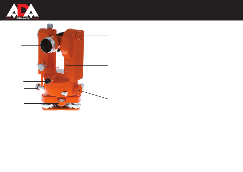
Fig.2 Photograph of the theodolite
4. CONSTRUCTION FEATURES
1.Optical aimer
2.Focussing sleeve of telescope
3.Reading eyepiece
4.Telescope eyepiece
5.Circle-setting knob
6.Сlamping screw of tribrach
7.Foot screw
8.Tribrach
9.Vertical compensator clamp
10.Micrometer knob
11.Change-over knob
12.Plate level
13.Adjusting screw for plate level
1
2
3
4
5.
6
7
8
10
9
12
11
13
PROF X2
Page 7
MEASUREMENT FOUNDATION
Fig.3 Photograph of the theodolite
3.The color visual field makes reading soft and smoothing to the eye.
4.The large aperture and the high magnifying power of the telescope lens ensure the possibility of getting a sharp image quality
even under relatively poor lighting conditions.
5.Loosen the screw that fastens tribrach and the upper part of the instrument can be dismounted from it to allow the mounting
of accessories.
Theodolite is equipped with optical plummet (5), which enables users to center the instrument over the point.
13.Telescope lens
14.Cover plate for index error
15.Eyepiece of optical plummet
16.Circular level
17.Vertical drive
18.Horizontal drive
19.Illuminating mirror for horizontal circle
20.Illuminating mirror for vertical circle
21.Knobs fix the position of axis
20
14
16
21
19
18
17
15
13
21
PROF X2
7
Page 8

8
PROF X2
5. HOW TO USE THE INSTRUMENT
1. Positioning the tripod.
Place the tripod over the measuring point and set the three legs almost equidistant to it. The place of mounting should be as
level as possible. Turn the wing clamps on the legs clockwise. It will enable them to be properly extended. The pointed shoes on
the tips of the legs should pierce the surface of the ground somewhat so that the tripod is surely erected and reliable as
surveying work is being performed on it.
2. Mounting the instrument on the tripod.
Place the instrument carefully on the tripod and tighten the central screw properly.
3. Adjusting the level of the instrument.
Use the circular level and foot screws of tribrach to roughly adjust the level of the instrument and then use the tubular one to do
precision levelling.
Levelling with circular level: Turn the screws 1 and 2, as shown in figure 4A, so that the bubble moves to the central line of
the circular level, and then turn the screw 3, as shown in figure 4B, so that the bubble is exactly in the center of the level.
3
1
Fig.4A
2
Fig.4B
MEASUREMENT FOUNDATION
Page 9

MEASUREMENT FOUNDATION
Levelling with the tubular level: Turn the alidade of theodolite first in order to make the tubular level parallel to the line
connecting the centers of any two foot screws (Fig. 5A), and at the same time, turn the two foot screws to enable the bubble to
position itself in the middle of the tubular level. Then turn the alidade 90° (Fig. 5B) and also turn the third foot screw to make the
bubble move to the middle of the level. Repeat the above described procedure several times so that the offset of the bubble
doesn't exceed the allowance for whatever position the alidade is turned.
4. Mounting the instrument properly over the measuring point.
Use an optical plummet to enable the center of the vertical axis of the theodolite to be directly over the plummet line of measuring
point. When the optical plummet is used, pull out its visual lens and turn it so that the measuring point is distinctly imaged on the
graduated plate. If the center of the measuring point is not in the center of the graduated plate, loosen the central screw of the
tripod. Then tighten the central screw of the tripod, and check the levelling of the instrument. Turn the alidade 180° and repeat
the above described procedure.
5. Illumination
Turning the position of the light reflection mirror (11) properly will result in a bright illumination of the graduated circle.
Fig.5A
Fig.5B
PROF X2
9
Page 10
10
6. Angle measurement
1. Turn the telescope to the given point. Use the rough optical sighting device to aim at the
object.
Then rotate the eyepiece in the counter-clockwise direction until the clear image of reticule.
Turn the focussing sleeve of the telescope so that the object will be clearly imaged on the
graduated plate.
2. Fix the position of telescope with the help of horizontal and vertical (21) clamps.
Turn both horizontal and vertical micrometer screws (17 and 18) so that the telescope is
precisely aimed at the target to be measured. At this moment, move the eye left and right,
and then up and down. In doing so, no relative displacement should be detected between
the target image and the graduation marks on the graduated plate. This means that no
parallax exist.
PROF
Рис.6А Рис.6B
X2
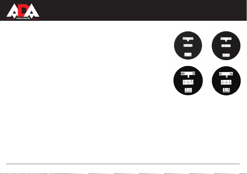
7. Graduated circle reading.
After illuminating the graduated circle, adjust the reading eyepiece (4) so that the reading visual
field, as shown in Fig.6, can be seen distinctly. The symbols H and V indicate the readings of the
horizontal and the vertical circles respectively. There are 60 graduations to every division (1') on
the tape and so estimation readings up to 0,1. And the reading error 0,05-0,1 of the graduated
circle corresponds to 3"-6" angular sec. The system of readings of vertical angles starts from
the horizon 90°. Before making the reading on the vertical circle, it is necessary to turn the locking
knob (10) of the automatic compensator to enable the compensator index mechanism to be in a
free state. At this moment very distinct sound is audible. And only then you can take the readings
of the vertical circle.
Рис.7А Рис.7B
MEASUREMENT FOUNDATION
Page 11

MEASUREMENT FOUNDATION
6. ADJUSTING THE THEODOLITE
8. Stadia measurement.
There are two pairs of short hairs on the graduated plate of the telescope, i.e. stadia hairs. They are used to measure the
distance between the target to be measured and the measurement point of the instrument.
Assume the distance between the staff and the measuring point is D. The length cut by a pairs of the stadia hairs on the scale
is L and constants of the stadia are K and C which are 100 and 0 respectively. The distance measurement formula is following:
D=KL+C-100L
Formula of horizontal distance, taking into account a slope:
D=KLC*OS a, where a- a vertical angle of slope
Formula for calculation the exceeding between points:
H=0,5 kL siin2a +1-v, where l- height of theodolite, v- height of aiming at the staff.
9. Using the rotary circle mechanism.
Theodolites Prof X2 are equipped with a rotary circle knob (5). It enables the reading value of the horizontal graduated
circle to be placed in the direction of the target to be measured. To avoid errors, it is necessary to aim at the target, to press the
locking catch of the rotary knob (5) and press the knob (5) simultaneously. Then, rotating the knob (5) in the counter-clockwise
direction, set the necessary reading. After this procedure press the locking catch again to unlock the limb.
All instruments are adjusted and checked and then transported to users after careful packing. But nevertheless before usage it is
necessary to repeat the adjustment as the transportation and storing conditions may tend to engender the possibility of deviation
from correct positions adjusted originally.
Such adjustment should be done as follows:
1. Adjusting the tubular level of the alidade
Turn the alidade so as to enable the tubular level to be parallel with the line connecting the centers of any two of foot screws.
PROF X2
11
Page 12

12
MEASUREMENT FOUNDATION
Turn the two screws in opposite directions equally so that the bubble will be in the middle of the level. Turn the alidade 90° and
with the third screw make the bubble in the middle of the level. Turn the alidade 90° again. If it's necessary, make the bubble in
the center again. Turn the alidade 180°. If the bubble is not in the middle, you should do further adjustment.
The foot screw on the half to which the bubble deviates should be turned so as to eliminate the offset value.
The other half can be corrected by turning the screw on the tubular level. For convenience, use the special pin.
2. Adjusting the circular level.
After adjusting the tubular level you should adjust the circular level. If the bubble of the circular level deviates from the center,
adjust it with three adjusting screws, which are under the level.
3. Adjusting the reticule of the telescope.
Focus the telescope at a plummet about 50 metres away. With micrometer screw, overlay the image of the top of the vertical
hair of telescope with the image of plummet of the hair. If they differ in more than 3 strokes, it's necessary to do the adjustment.
1. Screw the protective cap of the graduated plate of the telescope in the counter-clockwise direction and take it off. You see the
four adjusting screws on the frame.
2. Loosen the four adjusting screws with the help of screwdriver. Turn the frame of the graduated plate to enable the hair to be
vertical. Fix carefully new position of the frame tightening the screws. Repeat the adjustment.
4. Correcting the collimation axis error 2c
Place the theodolite at distance 100 metres from the target. Level the instrument and then check it.
1. Focus the telescope at the target in the position of the instrument “circle left” and take horizontal circle reading Л1.
2. Repeat the same focusing but in the position of the instrument “circle right” Take reading П1.
3. Loosen clamp finger of the support, turn theodolite 180° and then fix the clamp finger again.
4. Calculate the value of collimation axis error:
c=0,25[(Л1-П1±180°)=(Л2-П2±180°)]
PROF X2
Page 13

MEASUREMENT FOUNDATION
Repeat one more time the definition of collimation axis error ( c) and calculate it's average
value. The value difference shouldn't exceed 2”. If this value is more than 2" you should
do the adjustment. The procedure of correcting of collimation axis error is described below.
5. The adjustment of the place of zero (MO) of the vertical circle.
After leveling the instrument, observation should be done on the target (point) at two positions
of the circle of theodolite. The locking knob (10) of the compensator should be ON.
The place of zero is calculated according to the following formula:
МО=0,5 (Л-П) for theodolites with precise system of reading of vertical angles from 0°.
МО=0,5 (Л+П)-360° for theodolites with precise system of reading of vertical angles from 90°.
Where Л and П- reading of vertical circle.
Repeat the definition of the place of zero (МО) and calculate average value. The value shouldn't exceed 2".
If this value is more than 2" you should do the adjustment in accordance with the adjustment ( c):
Focus the levelled instrument at the target and take the readings Л of the horizontal and vertical circles.
Calculate the correction with the help of following formulas:
correction Л= Л – с for horizontal circle
correction Л= Л – МО for vertical circle
Set the corrected report of H circle with the help of horizontal micrometer screw.
The same way, set the corrected report of V circle.
With the help of the pin or screwdriver loosen adjustment screws to overlay the reticule image with the target.
Notice! You should correct 2c first, and only then- МО
Notice! You can correct МО with the help of corrective screws under the protective cover plate (13).
Fig.7
PROF X2
13
Page 14

PROF
X2
7. PRECAUTIONS
The theodolite is a precise optical instrument. Improper storage and usage can lead to its breakage, shorten its service life,
and even affect its normal use in surveying work.
The rules of operation and transportation of the theodolite:
1. Keep the instrument in the dry, clean and well-ventilated room (the temperature shouldn't be below 25°C and humidity
below 70%).
2. Place the instrument on its place in the case. When you take it out, hold with one hand the tribrach and with
another- alidade. Try not to touch the telescope.
3. When you focus on the target use horizontal and vertical micrometer screws, try to rotate them clockwise.
4. Doing this, rotate the instrument holding the alidade. Do not use for this purpose the telescope.
5. In the hot weather to protect the instrument from the sunlight, use the umbrella. Use the umbrella or the rain cover to protect
the instrument from the rain.
6. After using the instrument, remove all dust and dirt from its surface, and then put the instrument into a clean, dry case.
7. To clean the lens use the soft hair brush and then use absorbent cotton or cleaning paper to clean it.
8. When transporting the instrument, put the instrument into the case to avoid shaking.
9. Use the instrument only with purpose.
14
MEASUREMENT FOUNDATION
Page 15

PROF
X2
MEASUREMENT FOUNDATION
7. PRECAUTIONS
The theodolite is a precise optical instrument. Improper storage and usage can lead to its breakage, shorten its service life,
and even affect its normal use in surveying work.
The rules of operation and transportation of the theodolite:
1. Keep the instrument in the dry, clean and well-ventilated room (the temperature shouldn't be below 25°C and humidity
below 70%).
2. Place the instrument on its place in the case. When you take it out, hold with one hand the tribrach and with
another- alidade. Try not to touch the telescope.
3. When you focus on the target use horizontal and vertical micrometer screws, try to rotate them clockwise.
4. Doing this, rotate the instrument holding the alidade. Do not use for this purpose the telescope.
5. In the hot weather to protect the instrument from the sunlight, use the umbrella. Use the umbrella or the rain cover to protect
the instrument from the rain.
6. After using the instrument, remove all dust and dirt from its surface, and then put the instrument into a clean, dry case.
7. To clean the lens use the soft hair brush and then use absorbent cotton or cleaning paper to clean it.
8. When transporting the instrument, put the instrument into the case to avoid shaking.
9. Use the instrument only with purpose.
PROF X2
WARRANTY
This product is warranted by the manufacturer to the original purchaser to be free from defects in material and workmanship under normal use for a period of two (2) years from the date of purchase.
During the warranty period, and upon proof of purchase, the product will be repaired or replaced (with the same or similar model at manufactures option), without charge for either parts of labour.
In case of a defect please contact the dealer where you originally purchased this product. The warranty will not apply to
this product if it has been misused, abused or altered. Withiut limiting the foregoing, leakage of the battery, bending or
dropping the unit are presumed to be defects resulting from misuse or abuse.
EXCEPTIONS FROM RESPONSIBILITY
The user of this product is expected to follow the instructions given in operators’ manual.
Although all instruments left our warehouse in perfect condition and adjustment the user is expected to carry out periodic
checks of the product’s accuracy and general performance.
The manufacturer, or its representatives, assumes no responsibility of results of a faulty or intentional usage or misuse
including any direct, indirect, consequential damage, and loss of prots.
The manufacturer, or its representatives, assumes no responsibility for consequential damage, and loss of prots by any
disaster (earthquake, storm, ood ...), re, accident, or an act of a third party and/or a usage in other than usual condi-
tions.
The manufacturer, or its representatives, assumes no responsibility for any damage, and loss of prots due to a change
of data, loss of data and interruption of business etc., caused by using the product or an unusable product.
The manufacturer, or its representatives, assumes no responsibility for any damage, and loss of prots caused by usage
other thsn explained in the users’ manual.
The manufacturer, or its representatives, assumes no responsibility for damage caused by wrong movement or action
due to connecting with other products.
15
Page 16

WARRANTY DOESN'T EXTEND TO FOLLOWING CASES:
1. If the standard or serial product number will be changed, erased, removed or will be unreadable.
2. Periodic maintenance, repair or changing parts as a result of their normal runout.
3. All adaptations and modifications with the purpose of improvement and expansion of normal sphere of product application, mentioned in the
service instruction, without tentative written agreement of the expert provider.
4. Service by anyone other than an authorized service center.
5. Damage to products or parts caused by misuse, including, without limitation, misapplication or negligence of the terms of service instruction.
6. Power supply units, chargers, accessories, wearing parts.
7. Products, damaged from mishandling, faulty adjustment, maintenance with low-quality and non-standard materials, presence of any liquids
and foreign objects inside the product.
8. Acts of God and/or actions of third persons.
9. In case of unwarranted repair till the end of warranty period because of damages during the operation of the product, it's transportation and
storing, warranty doesn't resume.
For more information you can visit our web site WWW.ADAINSTRUMENTS.COM
or write the letter with your questions on info@adainstruments.com
Page 17

WARRANTY CARD
Name and model of the product ___________________________________________________
Serial number ____________________ date of sale_____________________
Name of commercial organization __________________ stamp of commercial organization
Warranty period for the instrument exploitation is 24 months after the date of original retail purchase. It extends to the equipment, imported on
the RF territory by official importer.
During this warranty period the owner of the product has the right for the free repair of his instrument in case of manufacturing defects.
Warranty is valid only with the original warranty card, fully and clear filled (stamp or mark of the seller is obligatory).
Technical examination of instruments for fault identification which is under the warranty, is made only in the authorized service center.
In no event shall manufacturer be liable before the client for direct or consequential damages, loss of profit or any other damage which occur
in the result of the instrument outage.
The product is received in the state of operability, without any visible damages, in full completeness. It is tested in my presence. I have no
complaints to the product quality. I am familiar with the conditions of warranty service and I agree.
purchaser signature________________________
Before operating you should read service instruction!
If you have any questions about the warranty service and technical support contact seller of this product.
Page 18

Certificate of acceptance and sale
№
name and model of the instrument
Corresponds to
designation of standard and technical requirements
Data of issue
Stamp of quality control department
Price
Sold
Date of sale
name of commercial establishment
Page 19

Руководство по эксплуатации
Оптический теодолит
Модель:
PROF X2
Производитель: ADAINSTRUMENTS Адрес: WWW.ADAINSTRUMENTS.COM
MEASUREMENT FOUNDATION
Page 20

PROF
X2
Оглавление
1. Описание . . . . . . . . . . . . . . . . . . . . . . . . . . . . . . . . . . . . . . . . . . . . . . . 21
2. Технические характеристики . . . . . . . . . . . . . . . . . . . . . . . . . . . . . . . . . . . . 21
3. Комплектация . . . . . . . . . . . . . . . . . . . . . . . . . . . . . . . . . . . . . . . . . . . . 22
4. Конструктивные особенности прибора . . . . . . . . . . . . . . . . . . . . . . . . . . . . . . .24
5. Использование теодолита . . . . . . . . . . . . . . . . . . . . . . . . . . . . . . . . . . . . . 26
6. Юстировка теодолита . . . . . . . . . . . . . . . . . . . . . . . . . . . . . . . . . . . . . . . .29
7. Меры предосторожности . . . . . . . . . . . . . . . . . . . . . . . . . . . . . . . . . . . . . . 32
8. Приложение 1 - „Свидетельство о приемке и продаже”
9. Приложение 2 - „Гарантийный талон”
RUS
Page 21

MEASUREMENT FOUNDATION
1. ОПИСАНИЕ
PROF
X2
Prof X2 - оптические теодолиты среднего класса точности. Приборы данного типа отличаются удобством в работе.
Теодолиты Prof X2 применяются в строительстве, в военном деле, геодезии и проектно - изыскательских работах.
Они, главным образом, используются для создания карт и планов различных масштабов, при выполнении съемок.
Прибор подойдет для использования при создании генеральных планов, муниципальном строительстве, при
обслуживании линий связи, в шахтах и т.д.
Теодолиты могут быть дополнительно укомплектованы различными принадлежностями для выполнения многих видов работ:
Штативами:
- ADA Strong, FS 23, M1Y.
- ADA Strongwood, FS 24 (SJJS50).
Рейкой:
- ADA Staff 3, 4, 5.
Вехой.
2. ТЕХНИЧЕСКИЕ ХАРАКТЕРИСТИКИ
Зрительная труба:
- изображение прямое
- увеличение 30-х
- диаметр объектива, мм 40
- угол поля зрения 1° 30'
- минимальное расстояние визирования 2 м
- коэффициент нитяного дальномера 100
- постоянное слагаемое дальномера 0
- длина зрительной трубы, мм 172
Спиртовые уровни:
- цилиндрический при алидаде, 30” / 2 мм
- круглый, 8' / 2 мм
21
Page 22

22
MEASUREMENT FOUNDATION
Градуировка и размеры лимбов:
- диаметр горизонтального круга (ГК), мм 94
- цена деления ГК 1°
- диаметр вертикального круга (ВК), мм 76
- цена деления ВК 1°
- цена деления шкалы микроскопа 1'
- увеличение горизонт. системы шкал микроскопа 68-х
- увеличение вертик. системы шкал микроскопа 65.4-х
СКО измерения угла одним приемом:
- горизонтального Prof X2 2”
- вертикального Prof X2 2”
Компенсатор вертикального круга:
- рабочий диапазон ±2'
Оптический центрир:
- увеличение 2,5-х
- угол поля зрения 5°
- диапазон фокусировки 0.7 м -
Вес и размеры:
- высота, мм 221
- вес прибора, кг 6
- вес футляра, кг 3.5
- вес штатива (пост. отдельно),кг 5,5
- высота штатива (сложен/разложен), м 1,0-1,5
∞
3. КОМПЛЕКТАЦИЯ
Теодолит со съемным трегером, футляр, бленда на объектив, отвес, юстировочная шпилька, отвертка, кисточка,
фланель протирочная, влагопоглотитель, чехол от дождя
PROF X2
Page 23

PROF X2
23
MEASUREMENT FOUNDATION
Page 24

24
1. Оптический визир
2. Кремальера (фокусировка) зр. трубы
3. Окуляр микроскопа
4. Окуляр зрительной трубы
5. Закрепительный винт перестановки лимба
6. Зажимной винт трегера
7. Подъемные винты
8. Трегер
9. Кнопка - винт блокировки/разблокировки компенсатора
10. Микрометрический винт при вертикальном и
горизонтальном круге
11. Переключение режимов снятия отсчетов вертикального
и горизонтального круга
12. Ампула цилиндрического уровня, защищена стальной
колбой
13. Юстировочные винты цилиндрического уровня
Рис.2 Фотография теодолита
4. КОНСТРУКТИВНЫЕ ОСОБЕННОСТИ ПРИБОРА
1
2
3
4
5
6
7
8
10
9
12
11
13
1. Конструкция инструмента проста и оригинальна. Это позволяет сочетать в себе легкость, компактность и прямое
быстрое снятие отсчетов. При создании данного прибора использовались самые передовые технологии проектирования
и надежные материалы.
2. Данный теодолит снабжен автоматическим компенсатором вертикального круга с передовым V-образным удлиненным
типом маятника, который обеспечивает устойчивую работу при высокочастотных колебаниях. Это не только позволяет
достичь высокой точности в работе, но и делает теодолитную съемку простой и легкой, значительно повышая
производительность труда.
MEASUREMENT FOUNDATION
PROF X2
Page 25

MEASUREMENT FOUNDATION
13. Объектив
14. Крышка для доступа к юстировочным винтам для
исправления ошибки индекса вертикального круга
15. Окуляр центрира
16. Круглый уровень
17. Наводящий винт при вертикальном круге
18. Наводящий винт при горизонтальном круге
19. Зеркало освещения при горизонтальном круге
20. Зеркало освещения при вертикальном круге
21. Зажимные винты фикстируют положение осей
Рис.3 Фотография теодолита
3. Цветные фоновые поля в отсчетном устройстве делают процесс снятия отсчетов удобным и не утомляют глаза.
4. Большой диаметр линз объектива и мощное увеличение зрительной трубы гарантируют возможность получения
четкого изображения даже в условиях недостаточного освещения.
5. Ослабив зажимной винт трегера, который закрепляет трегер и верхнюю часть прибора, можно вынуть прибор для
установки других принадлежностей.
Теодолит снабжен встроенным оптическим центриром (15), который позволяет пользователям выполнить точную
центровку прибора над точкой.
20
14
16
21
19
18
17
15
13
21
PROF X2
25
Page 26

26
MEASUREMENT FOUNDATION
1. Установка штатива.
Установите штатив над измеряемым пунктом (станцией) так, чтобы его ножки были равноудалены от него.
Место установки должно быть, насколько возможно, ровным. Ослабьте зажимные винты на штативе, выдвиньте ножки
на необходимую высоту и закрепите их теми же винтами.
Углубите ножки штатива в грунт так, чтобы он был надежно установлен для выполнения съемочных работ.
2. Установка инструмента на штатив.
Установите инструмент на площадке штатива, приблизительно над точкой и закрепите его при помощи станового винта.
3. Приведение инструмента к горизонту.
Используя круглый уровень и подъемные винты трегера грубо отгоризонтируйте теодолит, а затем выполните точную
установку и центровку при помощи цилиндрического уровня при алидаде и ножек штатива.
Горизонтирование прибора круглым уровнем: Поворачивая винты 1 и 2, как показано на рисунке 4А, добейтесь,
чтобы пузырек переместился как можно ближе к центру уровня и затем поворотом винта 3, как показано на рисунке 4В,
добейтесь, чтобы пузырек был точно в центре уровня.
5. ИСПОЛЬЗОВАНИЕ ТЕОДОЛИТА
Рис.4А
Рис.4В
1
2
3
PROF X2
Page 27

PROF
Горизонтирование прибора цилиндрическим уровнем: Поверните алидаду теодолита так, чтобы цилиндрический
уровень был параллелен линии, соединяющей центры любых двух подъемных винтов (Рисунок 5А) и в это же время,
поворачивая эти винты в противоположные стороны, переместите пузырек в центр ампулы. После этого, поверните
алидаду прибора на 90 градусов (Рисунок 5В) и также, поворачивая третий винт, добейтесь положения пузырька уровня
точно по центру ампулы. Повторите описанную процедуру несколько раз так, чтобы смещение пузырька не превысило
одно деление ампулы при любом угле поворота прибора.
X2
Рис.5А
4. Установка инструмента над пунктом.
Используя оптический центрир теодолита необходимо добиться совпадения вертикальной оси вращения прибора с
центром пункта. Выдвигая на себя или задвигая от себя окуляр центрира, добейтесь четкого изображения пункта.
Вращением подъемных винтов трегера совместите изображение пункта с центром круга сетки нитей центрира. Путем
регулировки длины ножек штатива, приведите пузырек уровня при алидаде в ноль-пункт (центр уровня). Если центр сетки
нитей отклонится от изображения пункта, совместите его путем перемещения прибора по площадке штатива. Закрепите
теодолит становым винтом и проверьте положение уровня при помощи подъемных винтов трегера. Повторите
вышеуказанные действия, повернув алидаду на 180 градусов.
5. Освещение.
Поверните зеркало (19) по направлению к свету и добейтесь равномерного освещения шкал должным образом.
27
Рис.5В
MEASUREMENT FOUNDATION
Page 28

28
Затем поверните ручку (11) в вертикальное положение, откройте зеркало (20) и повторите операцию.
6. Измерение углов.
1. Поверните зрительную трубу по направлению к заданной точке. При
помощи оптического визира (1) грубо наведитесь на марку (вешку). Вращая
окуляр против часовой стрелки, добейтесь четкого изображения штрихов сетки
нитей, поверните кремальеру, добейтесь четкой фокусировки объекта измерений.
2. Зафиксируйте с помощью горизонтальных и вертикальных (21) зажимов
положение зрительной трубы. Используя наводящие микрометрические винты
горизонтального и вертикального кругов (ГК и ВК) (18) и (17) и микрометрическим
винтом (10) выполните точное наведение. Переместите глаз вправо, затем
вверх и вниз. При этом никакого относительного смещения между изображением
и целью не должно быть. Это означает отсутствие параллакса.
Рис.6А Рис.6B
PROF X2
7. Отсчитывание по кругам.
После регулировки освещенности шкал кругов, добейтесь при помощи винта фокусировки отсчётного микроскопа (3)
чёткого изображения шкал, как показано на Рис.6 или 7. Цвет шкал (ВК – голубой; ГК - коричневый) и штрих,
нанесенный на переключающем механизме (11), указывает на их принадлежность к горизонтальному и вертикальному
кругам соответственно (при горизонтальном положении штриха ГК, при вертикальном положении штриха ВК). На каждый
круг (ВК и ГК) приходиться две шкалы. Верхняя шкала показывает целое число градусов, минут в десятых долях, а
нижняя показывает секунды в десятках, и единицы минут (нанесены поверх секундных цифр). Нижняя шкала разбита на
60 делений. Каждое деление соответствует одной угловой секунде. Доли делений оцениваются на глаз с округлением
до 0,1. При этом, погрешность отсчитывания 0,05 - 0,1 деления шкалы соответствует долям угловых секунд. Перед тем
как снять отсчет по ВК или ГК необходимо убедиться, что штрихи, нанесенные в центре отсчетного устройства между
шкал, совмещены (верхняя и нижняя полоса) как показано на рис. 6B и 7B.Система отсчётов вертикальных углов
начинается от горизонта 90 градусов. Перед снятием отсчёта по вертикальному кругу, необходимо повернуть кнопку
(10 - блокировка компенсатра) в положении ON, чтобы позволить механизму компенсатора быть в свободном состоянии.
При этом. Вы услышите характерный звук только после этого можно снимать отсчёты по вертикальному кругу.
Рис.7А Рис.7B
MEASUREMENT FOUNDATION
Page 29

PROF X2
8. Измерение расстояний при помощи нитяного дальномера.
В поле зрения зрительной трубы есть две пары дальномерных штрихов (в вертикальной и горизонтальной плоскости
соответственно). Они используются, чтобы измерить расстояние между рейкой и пунктом установки прибора.
Примем искомое расстояние между рейкой и пунктом как D.
Длина отрезка L, по рейке с сантиметровыми делениями, между дальномерными штрихами, К и С постоянные, которые
равны 100 и 0 соответственно. Формула для вычисления наклонного расстояния будет следующей:
D=KL+C-100L
Формула для вычисления горизонтального проложения:
D=KLC*OS a, где а - вертикальный угол наклона
Формула для вычисления превышения между точками:
Н=0.5 kL siin2a + 1-v, где I - высота теодолита, v - высота визирования по рейке
9. Использование винта перестановки отсчета по горизонтальному лимбу.
Теодолиты Prof X2 оборудованы винтом перестановки по горизонтальному лимбу (5). Это позволяет изменять
отсчет по лимбу горизонтального круга, по направлению на цель, которая будет измерена. Во избежание ошибок,
сначала необходимо навестись точно на цель, нажать на стопорную защелку, которая находится на винте (5),
и одновременно нажать на винт (5). Затем, вращая винт по или против часовой стрелки, установить требуемый отсчет.
По окончании - вновь нажать на стопорную защелку для разблокировки лимба.
6. ЮСТИРОВКА ТЕОДОЛИТА
Все теодолиты точно отрегулированы и поверены, упакованы, осторожно транспортируются пользователям.
Тем не менее, перед их использованием, необходимо повторить юстировку, так как транспортировка и условия хранения
могут привести к отклонению настроек, первоначально установленных на заводе.
Следующая юстировка (поверка) должна быть выполнена обязательно:
1. Юстировка цилиндрического уровня при алидаде.
Ось уровня должна быть перпендикулярна оси вращения теодолита. Поверните алидаду так, чтобы ось
цилиндрического уровня была параллельна воображаемой линии, соединяющей центры любых двух подъемных винтов
трегера.
29
MEASUREMENT FOUNDATION
Page 30

30
PROF
Одинаковыми поворотами двух винтов в противоположные стороны добейтесь, чтобы пузырек был в середине ампулы.
Поверните алидаду на 90 градусов и при помощи третьего винта выведите пузырек на середину. Поверните алидаду
еще раз на 90 градусов. Сделайте доводку пузырька на середину (если это необходимо). Поверните алидаду на 180
градусов. Если отклонение пузырька больше одного деления, то необходимо выполнить дальнейшую юстировку.
Половину велечины смещения пузырька необходимо исправить при помощи подъемных винтов, а другую - с помощью
юстировочного винта цилиндрического уровня. Для удобства, используйте специальную шпильку, из комплекта
прибора.
2. Юстировка круглого уровня на трегере.
После юстировки цилиндрического уровня, необходимо сразу отрегулировать круглый уровень. Если пузырек круглого
уровня отклоняется от центра, отрегулируйте его положение при помощи трех юстировочных винтов, которые
располагаются под уровнем.
3. Юстировка сетки нитей зрительной трубы.
Наведите зрительную трубу на отвес, расположенный на расстоянии, приблизительно, 50 метров. Совместите, при
помощи микрометрического винта ГК, изображение верха вертикальной нити зрительной трубы с изображением нити
отвеса. Проверьте расхождение концов изображений. Если они различаются более чем на три ширины штриха необходимо выполнить юстировку.
1. Отвернув против часовой стрелки защитный колпачок, расположенный перед окуляром зрительной трубы, Вы увидите
4 малых юстировочных винта, расположенных на рамке.
2. Ослабьте эти четыре регулировочных винта при помощи отвертки, и поверните рамку до положения, чтобы
изображения штрихов совпали. Аккуратно зафиксируйте новое положение рамки, закрутив винты. Повторите проверку.
4. Юстировка коллимационной погрешности 2с (неперпендикулярности визирной и горизонтальной осей
теодолита).
Разместите теодолит на расстоянии, приблизительно 100 метров от цели. Отгоризонтируйте инструмент и затем
проверьте это:
1. Наведите зрительную трубу на цель при положении прибора „круг лево” и возьмите отсчет Л1 по горизонтальному кругу.
2. Повторите наведение на ту же цель, но при положении „круг право”. Возьмите отсчет П1.
3. Ослабьте закрепительный винт подставки, поверните теодолит на 180 градусов и снова закрепите его.
4. Вычислите величину коллимационной погрешности по формуле:
с=0,25 [(Л1 - П1 ± 180° ) = (Л2 - П2 ± 180° )]
MEASUREMENT FOUNDATION
X2
Page 31

PROF X2
Повторите еще раз определение коллимационной погрешности (с) и вычислите ее среднее
значение. Разность между значениями не должна превышать 2”. Если это значение
больше допустимого - необходимо выполнить юстировку. Коллимационную погрешность
исправляют при помощи горизонтальных исправительных винтов зрительной трубы,
находящихся под защитным колпачком. Методика исправления будет описана ниже,
совместно с исправлением места нуля (МО) вертикального круга.
5. Юстировка места нуля (МО) вертикального круга.
После выравнивания инструмента, должны быть выполнены наблюдения на удаленную цель (точку) при двух
положениях круга теодолита. Обратите внимание на положение переключателя (10) - должно быть ON (компенсатор
включен). Место нуля вычисляется до целого по формуле:
МО=0,5 (Л-П) для теодолитов с отсчетной системой верт. углов от 0 градусов
МО=0,5 [(Л+П)-360° ] для теодолитов с отсчетной системой верт. углов от 90 градусов
Где Л и П - отсчеты по вертикальному кругу.
Повторите определение МО еще раз и вычислите среднее значение, оно не должно превышать 2”. Если больше необходимо выполнить юстировку совместную с юстировкой (с) следующим образом:
Наведите отгоризонтированный прибор на удаленную цель и снимите отсчеты Л по горизонтальному и вертикальному кругам.
Вычислите соответствующие поправки по формулам:
Лиспр.=Л - с для горизонтального круга
Лиспр.=Л-МО для вертикального круга
Установите исправленный отсчет по ГК при помощи наводящего и микрометрического винтов горизонтального круга.
Таким же образом, установите исправленный отсчет по вертикальному кругу.
При помощи шпильки или отвертки ослабьте юстировочные винты и добейтесь совмещения изображения сетки нитей с
целью. Повторите измерения и убедитесь в правильности произведенной Вами юстировки.
ВНИМАНИЕ! Сначала нужно исправить 2с, а потом - МО. Перед наведением зрительной трубы на цель и перед
смещением сетки нитей, следите за положением цилиндрического уровня, каждый раз подправляйте его положение
подъемными винтами трегера.
ПРИМЕЧАНИЕ! Исправление МО можно проводить и при помощи исправительных винтов, находящихся под защитной
крышкой (13).
31
MEASUREMENT FOUNDATION
Рис.7
Page 32

PROF
PROF
X2
7. МЕРЫ ПРЕДОСТОРОЖНОСТИ
Теодолит - точный оптический прибор. Ненадлежащее хранение и использование могут привести к его поломке,
сократить срок службы, и даже повлиять на качество выполняемых съемочных работ.
Правила работы и транспортировки теодолита:
1. Храните прибор в сухом, чистом и хорошо проветриваемом помещении (температура не ниже 25° С, влажность не
более 70%).
2. Правильно укладывайте прибор в футляр. При выемке прибора из футляра, одна рука должна охватывать трегер, а
другая алидаду. Старайтесь при этом не браться за зрительную трубу.
3. При точном наведении на цель с использованием микрометрических винтов ГК и ВК, старайтесь крутить их по
часовой стрелке.
4. При выполнении наведения на цель, вращайте прибор, удерживая рукой алидаду. Не используйте для этой цели
зрительную трубу.
5. В жаркую погоду, для защиты прибора от попадания прямых солнечных лучей используйте зонт. Используйте зонт
или чехол для защиты прибора от дождя.
6. После использования удалите салфеткой всю пыль и грязь с поверхности теодолита, и затем поместите в чистый,
сухой кейс.
7. Для чистки линзы объектива используйте сначала специальную мягкую кисточку, а затем аккуратно протрите ватой
или чистящей салфеткой.
8. При транспортировке укладывайте прибор в футляр во избежание резких ударов и толчков, которые могут привести
к повреждению и разъюстировке.
9. Не используйте теодолит не по назначению!
X2
32
MEASUREMENT FOUNDATION
Page 33

PROF
X2
MEASUREMENT FOUNDATION
7. МЕРЫ ПРЕДОСТОРОЖНОСТИ
Теодолит - точный оптический прибор. Ненадлежащее хранение и использование могут привести к его поломке,
сократить срок службы, и даже повлиять на качество выполняемых съемочных работ.
Правила работы и транспортировки теодолита:
1. Храните прибор в сухом, чистом и хорошо проветриваемом помещении (температура не ниже 25° С, влажность не
более 70%).
2. Правильно укладывайте прибор в футляр. При выемке прибора из футляра, одна рука должна охватывать трегер, а
другая алидаду. Старайтесь при этом не браться за зрительную трубу.
3. При точном наведении на цель с использованием микрометрических винтов ГК и ВК, старайтесь крутить их по
часовой стрелке.
4. При выполнении наведения на цель, вращайте прибор, удерживая рукой алидаду. Не используйте для этой цели
зрительную трубу.
5. В жаркую погоду, для защиты прибора от попадания прямых солнечных лучей используйте зонт. Используйте зонт
или чехол для защиты прибора от дождя.
6. После использования удалите салфеткой всю пыль и грязь с поверхности теодолита, и затем поместите в чистый,
сухой кейс.
7. Для чистки линзы объектива используйте сначала специальную мягкую кисточку, а затем аккуратно протрите ватой
или чистящей салфеткой.
8. При транспортировке укладывайте прибор в футляр во избежание резких ударов и толчков, которые могут привести
к повреждению и разъюстировке.
9. Не используйте теодолит не по назначению!
PROF X2
Гарантия
Производитель предоставляет гарантию на продукцию покупателю в случае дефектов материала или качества его
изготовления во время использования оборудования с соблюдением инструкции пользователя на срок до 1 года со
дня покупки. Во время гарантийного срока, при предъявлении доказательства покупки, прибор будет починен или
заменен на такую же или аналогичную модель бесплатно. Гарантийные обязательства также распространяются и
на запасные части.
В случае дефекта, пожалуйста, свяжитесь с дилером, у которого вы приобрели прибор. Гарантия не
распространяется на продукт, если повреждения возникли в результате деформации, неправильного
использования или ненадлежащего обращения.
Все вышеизложенные безо всяких ограничений причины, а также утечка батареи, деформация прибора являются
дефектами, которые возникли в результате неправильного использования или плохого обращения.
Освобождение от ответственности
Пользователю данного продукта необходимо следовать инструкциям, которые приведены в руководстве по
эксплуатации. Даже, несмотря на то, что все прборы проверены производителем, пользователь должен проверять
точность прибора и его работу.
Производитель или его представители не несут ответственности за прямые или косвенные убытки, упущенную
выгоду или иной ущерб, возникший в результате неправильного обращения с прибором.
Производитель или его представители не несут ответственности за косвенные убытки, упущенную выгоду,
возникшие в результате катастроф (землетрясение, шторм, наводнение и т.д.), пожара, несчастных случаев,
действия третьих лиц и/или использование прибора в необычных условиях.
Производитель или его представители не несут ответственности за косвенные убытки, упущенную выгоду,
возникшие в результате изменения данных, потери данных и временной приостановки бизнеса и т.д., вызванных
применением прибора.
Производитель или его представители не несут ответственности за косвенные убытки, упущенную выгоду,
возникшие в результате использования прибора не по инструкции.
33
Page 34

ГАРАНТИЙНЫЕ ОБЯЗАТЕЛЬСТВА НЕ РАСПРОСТРАНЯЮТСЯ НА СЛЕДУЮЩИЕ СЛУЧАИ:
1.Если будет изменен, стерт, удален или будет неразборчив типовой или серийный номер на изделии.
2.Периодическое обслуживание и ремонт или замену запчастей в связи с их нормальным износом.
3.Любые адаптации и изменения с целью усовершенствования и расширения обычной сферы применения изделия, указанной в
инструкции по эксплуатации, без предварительного письменного соглашения специалиста поставщика.
4.Ремонт, произведенный не уполномоченным на то сервисным центром;
5.Ущерб в результате неправильной эксплуатации, включая, но не ограничиваясь этим, следующее: использование изделия не по
назначению или не в соответствии с инструкцией по эксплуатации на прибор;
6.На элементы питания, зарядные устройства, комплектующие, быстроизнашивающиеся и запасные части;
7.Изделия, поврежденные в результате небрежного отношения, неправильной регулировки, ненадлежащего технического
обслуживания с применением некачественных и нестандартных расходных материалов, попадания жидкостей и посторонних
предметов внутрь.
8.Воздействие факторов непреодолимой силы и/или действие третьих лиц
9.В случае негарантийного ремонта прибора до окончания гарантийного срока, произошедшего по причине получанных повреждений
в ходе эксплуатации, транспортировки или хранения, и не возобновляется.
Для получения дополнительной информации Вы можете посетить наш Интернет сайт WWW.ADAINSTRUMENTS.COM
или написать письмо с интересующими Вас вопросами на электронный адрес info@adainstruments.com
Page 35

Наименование изделия и модель ________________________________________________________
Серийный номер _______________________ Дата продажи ____________________
Наименование торговой организации _______________________ Штамп торговой организации мп.
Гарантийный срок эксплуатации приборов составляет 24 месяца со дня продажи и распространяется на оборудование, ввезенное на
территорию РФ официальным импортером.
В течении гарантийного срока владелец имеет право на бесплатный ремонт изделия по неисправностям, являющимся следствием
производственных дефектов.
Гарантийные обязательства действительны только по предъявлении оригинального талона, заполненного полностью и четко (наличие
печати или штампа с наименованием и формой собственности продавца обязательно).
Техническое освидетельствование приборов (дефектация) на предмет установления гарантийного случая производится только в
авторизованной мастерской.
Производитель не несет ответственности перед клиентом за прямые или косвенные убытки, упущенную выгоду или иной ущерб,
возникшие в результате выхода из строя приобретенного оборудования.
Правовой основой настоящих гарантийных обязательств является действующее законодательство, в частности, Федеральный закон
РФ «О защите прав потребителя» и Гражданский Кодекс РФ ч.II ст. 454-491.
Товар получен в исправном состоянии, без видимых повреждений, в полной комплектности, проверен в моем присутствии, претензий
по качеству товара не имею. С условиями гарантийного обслуживания ознакомлен и согласен.
Подпись покупателя ____________________
По вопросам гарантийного обcлуживания и технической поддержки обращаться к продавцу данного товара
Page 36

Свидетельство о приемке и продаже
№
наименование и тип прибора
Соответствует
обозначение стандарта и технических условий
Дата выпуска
Штамп ОТК (клеймо приемщика)
Цена
Продан(а)
Дата продажи
наименование предприятия торговли
Page 37

Page 38

MEASUREMENT FOUNDATION
WWW.ADAINSTRUMENTS.COM
ADA
 Loading...