

Page 1

Operating manual
Digital level
Model: ProDigit 60
Manufacturer: ADAINSTRUMENTS Address: WWW.ADAINSTRUMENTS.COM
Page 2

ProDigit 60
Table of contents
1. Safety symbols . . . . . . . . . . . . . . . . . . . . . . . . . . . . . . . . . . . . . . . . . . . . . . . . . . . . . . 3
2. Safety instructions . . . . . . . . . . . . . . . . . . . . . . . . . . . . . . . . . . . . . . . . . . . . . . . . . . . . 4
3. Features . . . . . . . . . . . . . . . . . . . . . . . . . . . . . . . . . . . . . . . . . . . . . . . . . . . . . . . . . 6
4. Specications. . . . . . . . . . . . . . . . . . . . . . . . . . . . . . . . . . . . . . . . . . . . . . . . . . . . . . . 9
5. Calibration. . . . . . . . . . . . . . . . . . . . . . . . . . . . . . . . . . . . . . . . . . . . . . . . . . . . . . . .11
6. Measurements . . . . . . . . . . . . . . . . . . . . . . . . . . . . . . . . . . . . . . . . . . . . . . . . . . . . . 12
7. Maintenance . . . . . . . . . . . . . . . . . . . . . . . . . . . . . . . . . . . . . . . . . . . . . . . . . . . . . . 17
8. Troubleshooting . . . . . . . . . . . . . . . . . . . . . . . . . . . . . . . . . . . . . . . . . . . . . . . . . . . . . 18
9. Specic reasons for erroneous measuring results . . . . . . . . . . . . . . . . . . . . . . . . . . . . . . . . . . . . 19
10. Electromagnetic acceptability . . . . . . . . . . . . . . . . . . . . . . . . . . . . . . . . . . . . . . . . . . . . . . 19
11. Laser classication . . . . . . . . . . . . . . . . . . . . . . . . . . . . . . . . . . . . . . . . . . . . . . . . . . . 20
12. Warranty . . . . . . . . . . . . . . . . . . . . . . . . . . . . . . . . . . . . . . . . . . . . . . . . . . . . . . . . 20
13. Exceptions from responsibility . . . . . . . . . . . . . . . . . . . . . . . . . . . . . . . . . . . . . . . . . . . . . . 21
14. Appendix 1- “Certicate of acceptance and sale”
15. Appendix 2- “Warranty card”
Page 3

ProDigit 60
Safety symbols
The purpose of safety symbols is to attract your attention to possible dangers. The safety symbols, and the explanations with them, deserve your careful attention and understanding. The symbol warnings DO NOT by themselves eliminate any danger. The instructions and warnings they give are no substitutes for proper accident prevention measures.
WARNING: BE SURE to read and understand all safety instructions in this manual, including all safety alert symbols
such as “DANGER”, “WARNING” and “CAUTION”, BEFORE using this digital level. Failure to follow all instructions
listed below may result in electric shock, re and/or serious personal injury.
SYMBOL MEANING
SAFETY ALERT SYMBOL Indicates DANGER, WARNING, OR CAUTION. May be used in conjunction with other
symbols or pictographs.
DANGER Failure to obey this safety warning WILL result in death or serious injury to yourself or to others. Always
follow the safety precautions to reduce the risk of re, electric shock and personal injury.
WARNING Failure to obey this safety warning CAN result in death or serious injury to yourself or to others. Always
follow the safety precautions to reduce the risk of re, electric shock and personal injury.
CAUTION Failure to obey this safety warning MAY result in personal injury to yourself or others or property damage.
Always follow the safety precautions to reduce the risk of re, electric shock and personal injury.
DAMAGE PREVENTION AND INFORMATION MESSAGES
These inform user of important information and/or instructions that could lead to equipment or other property damage
if not followed. Each message is preceded by the word “NOTE:” as in the example below:
NOTE: Equipment and/or property damage may result if these instructions are not followed.
3
MEASUREMENT FOUNDATION
Page 4

ProDigit 60
Safety instructions
WARNING: BE SURE to read and understand all instructions in this manual before using this level. Failure to follow all instruc-
tions may result in hazardous radiation exposure, electric shock, re and/or serious personal injury.
SAFETY PRECAUTIONS FOR LASERS
WARNING: Use of controls, adjustments or performance of procedures other than those specied in this manual may result in
hazardous radiation exposure. WARNING: The use of optical instruments such as, but not limited to, telescopes or transits to
view the laser beam will increase eye hazard.
This level has a built-in laser light. The laser is a Class2 and emits output power of a maximum 1 mW and 635-665 nm wave-
lengths. These lasers do not normally present an optical hazard. However, DO NOT stare at the beam as this can cause ash
blindness. CAUTION: The following label is on your tool. It indicates level emits the laser light.
BE AWARE of the laser light location. ALWAYS MAKE SURE that any bystanders in the vicinity aware of the dangers of looking directly into the laser. WARNING: LASER RADIATION. DO NOT stare into beam. Class2 laser product.
Only turn laser beam on when the level is on the work surface.
DO NOT remove or deface any product labels. Removing product labels increases the risk of exposure to laser radia-
1.
tion.
DO NOT stare directly at the laser beam or project the laser beam directly into the eyes of others. Serious eye injury
2.
could result.
DO NOT place the Digital level in a position that may cause anyone to stare into the laser beam intentionally or uninten-
3.
tionally. Serious eye injury could result.
DO NOT use any magnifying optical tools such as, but not limited to, telescopes or transits to view the laser beam. Seri-
4.
ous eye injury could result.
DO NOT operate the Digital level around children or allow children to operate the tool. Serious eye injury could result.
5.
ALWAYS turn the Digital level off when not in use. Leaving the tool on increases the risk of someone inadvertently star-
6.
ing into the laser beam.
DO NOT operate the Digital Level in combustible areas such as in the presence of ammable liquids, gasses or dust.
7.
DO NOT use on surfaces such as sheet steel that have a shiny, reective surface. The shiny surface could reect the
8.
4
MEASUREMENT FOUNDATION
Page 5

ProDigit 60
beam back at the operator. Be aware that laser light reected off a mirror or any other reective surfaces can also be
dangerous.
DO NOT place the Digital level in a position that may cause anyone to stare into the laser beam intentionally or uninten-
9.
tionally. Serious eye injury could result.
DO NOT use any magnifying optical tools such as, but not limited to, telescopes or transits to view the laser beam. Seri-
10.
ous eye injury could result.
DO NOT operate the Digital level around children or allow children to operate the tool. Serious eye injury could result.
11.
ALWAYS turn the Digital level off when not in use. Leaving the tool on increases the risk of someone inadvertently star-
12.
ing into the laser beam.
DO NOT operate the Digital Level in combustible areas such as in the presence of ammable liquids, gasses or dust.
13.
DO NOT use on surfaces such as sheet steel that have a shiny, reective surface. The shiny surface could reect the
14.
beam back at the operator. Be aware that laser light reected off a mirror or any other reective surfaces can also be
dangerous.
DO NOT attempt to modify the performance of this laser device in any way. This may result in a dangerous exposure to
15.
laser radiation.
DO NOT use the Digital Level for any purpose other than those outlined in this manual. This could result in serious injury.
16.
ALWAYS USE two “AAA” size batteries. Use of any other batteries may create a risk of re. INSERT the batteries cor-
17.
rectly. Match the polarities, positive (+) to positive and negative (-) to negative, as marked inside battery compartment.
DO NOT short battery terminals.
18.
DO NOT mix old and new batteries. If batteries are weak, replace both of them with two new batteries. These new bat-
19.
teries should match each other in brand and type.
Remove dead batteries immediately and dispose of them according to your local ordinance.
20.
NEVER dispose of batteries in re.
21.
Keep batteries out of reach of children. They are not playthings.
22.
Remove batteries and store separately if level will not be used for several days.
23.
Do not attempt to repair or disassemble the laser level. If unqualied persons attempt to repair this laser product, serious
24.
injury may result. Any repair required on this laser product should be performed by authorized service center personnel.
5
MEASUREMENT FOUNDATION
Page 6

ProDigit 60
NOTE: Before attempting to use your level, familiarize yourself with all of the operating features and safety requirements.
This digital level is a highly versatile leveling tool designed for fast, easy operation.
Heavy-duty, lightweight aluminum construction, with the LCD digital module constructed of unbreakable ABS polymer that’s
sealed against dirt and water, and the toughest acrylic block bubble vials and solid-state laser components all add up to on-
the-job durability and long, dependable service.
Use the digital LCD readout for all your angle measurements and layout jobs, such as roof pitches, saw cut angles and drain-
age slopes.
Use the laser beam to extend a visual leveling line over distances much greater than a traditional bubble vial beam level.
Use the level manually, hand held, or mounted on a tripod (sold separately).
Use the digital level inside or outside to measure pitch in inches of rise per foot of run.
Measure in degrees with up to 0.05° accuracy.
Measure any slope in percent...measure level and plumb with either the LCD digital display or with the vertical and horizontal
bubble vials.
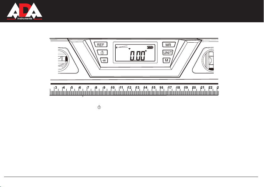
Features (Fig.1a)
Keyboard
1.
LCD Display - Large, easy-to-read display screen reads right side up even when level is upside down.
2.
Bubble Vials- The level or plumb of a surface can also be accurately measured by positioning the bubble inside the vial
3.
in between the marks on the vial’s surface. The highly sensitive vial ensure the digital level has an accuracy of 0.029°.
Integrated 57cm Ruler
4.
Laser On/OFF Button - Located on the right end cap of the level, powers the laser on/off.
5.
Endcaps - Ends cushioned to help protect level from damage.
6.
Laser Light Aperture - The laser beam is emitted from this opening, which is on the end cap of the level.
7.
Magnetic Bottom -Four magnets in the working base allow for secure contact to metal, handy when working with steel
8.
studs or metal ductwork.
1/4 -inch Tripod Threaded Hole - Allows level to be mounted to a 1/4 tripod, sold separately.
9.
6
MEASUREMENT FOUNDATION
Page 7

ProDigit 60
2
1
3
4
3
9
10
11
12
8
5
6
8
Working Base - The bottom of the level is the working base. The working base should always be placed rmly on the
10.
working surface. The working base is designed for at surfaces and also features a v-shaped groove for use on round
objects like pipe.
Battery Compartment - Holds two “AAA” batteries to power the laser and LCD display.
11.
Large, Soft-grip Handles - For ease in carrying, holding level in place.
12.
Fig.1a
7
MEASUREMENT FOUNDATION
Page 8

ProDigit 60
Key function (Fig.1b)
Power button-press the button to turn the LCD display screen on. Long press it to turn off the LCD display.
1.
REF Button - Push the button briey to set current angle to zero, enter relative angle measurement mode. Push the
2.
button for about 3 seconds to start the calibration.
Sound On/Off Button- Used to activate the beeper. When button is pushed, beeper sounds at level (0°), 45°, plumb
3.
(90°) and last saved angle. To turn sound off, simply push button again.
M Button - Push to save the current reading in its memory. The level will save last nine different consecutive angle read-
4.
ings in its memory.
MR Button - Push button to recall the last 9 measurements that are saved in the memory. They will read in order of the
5.
latest measurement entered as “rst”.
UNIT Button - By pushing this button you can convert angles to different units. Push to change the display units from
6.
degrees (°) to pitch (in / ft), to percent slope (%). Pitch readings are in 1/8-inch/feet increments. Plus and minus signs
indicate that the pitch is slightly more (+) or less (-) than true level.
8
MEASUREMENT FOUNDATION
Page 9

ProDigit 60
Recommended use Indoors or Outdoors
Laser class Class2, max laser output ≤1mW
Power supply 2x 1.5V AAA battteries
Angle measuring range 0 to 360°
Optimum operation range 0 to 40°
Accuracy of vials ±0.029°
Accuracy of digital display
±0.05°(level or plumb)
±0.1°(other angles)
Estimated Battery life 10 hours with alkaline batteries
LCD SCREEN ICONS
0
Up/Down Indicator - The zero line (0°) indicates the level position. The arrow indicates the current angle’s position,
either up or down away from the level (0°).
Battery Power Icon - Indicates the amount of battery power in the unit. Replace batteries when the black power bar
disappears.
Sound / Beeper Icon - This icon appears on the screen when the beeper function is activated.
M1-M9 Memory Icon - This icon shows when the memory function is being used. Level can recall the last nine saved
measurements.
REF Indicates that the level is working in relative angle mode.
Err Indicates that the level is wrong positioned or wrong operation in calibration.
CAL1 Indicates that the digital level is in calibrating for one direction.
CAL2 Indicates that the digital level is in calibrating for the another direction.
Specications
9
MEASUREMENT FOUNDATION
Page 10

ProDigit 60
+
-
Battery installation (Fig. 2)
This multi-function digital laser level uses two “AAA” batteries (sold separately), to power both the LCD module display and
the Laser dot.
Fig.2
NOTE: Always ensure the on/off button is in OFF position before installing or replacing the batteries.
Open the battery cover, located in the middle of the back of the level (Fig.2).
1.
Insert two new “AAA” alkaline batteries with the polarity (+/-) as indicated on the inside of the battery compartment.
2.
Close the cover securely in place.
3.
Turn on the LCD display
Press the Power button to turn the LCD display screen on. When the screen rst comes on, the temperature is displayed in
centigrade for about 2 seconds, to indicate if level is being used in optimum operating temperature range. The current angle
of the level is then displayed, and a picture of that angle is shown either above or below the line for true level. An arrow on
the display indicates if the level has to be moved up or down. True level is reached when the two lines are together and the
angle shows 0.00°. Turn off the LCD display by pressing and holding the button in for about 2 seconds. If the digital level is
not used for 5 minutes the level automatically turns off. The LCD display is large and easy to read. When the level is turned
upside down, the LCD screen senses and changes to read correctly in the inverted position.
10
MEASUREMENT FOUNDATION
Page 11

ProDigit 60
Calibration (Figs.3,4)
Place the digital level on a at and smooth surface, push and hold the REF button for about 3 seconds, the calibration
mode is activated. “CAL1” will wink on LCD.
Keep it unmoved for seconds until hear the beeper sounds for 1 second, then “CAL2” will show on LCD.
Rotate the level 180º in the same location then press the REF button, “CAL2” will wink, keep it unmoved for seconds, then
the beeper will sound for 2 seconds to tell calibrating completed, the LCD will show the current angle in high-accuracy-display.
Fig.3 Fig.4
Important NOTE:
The digital level has been pre-calibrated to high-accuracy-display mode. It possibly runs to rough-accuracy-display
•
mode if the temperature changes too much. Suggest calibrating the digital level every time before you use it.
To ensure an accurate measurement, the calibration should be performed separately for horizontal measurement,
•
plumb measurement or upside measurement.
The calibration must be performed on a at and smooth surface with the gradient no more than 5º. If it exceeds 5º, the
•
beeper will be buzzing for 3 seconds, “Err” will show on the LCD to tell the calibration failed, then exits automatically.
In the calibration, the level also can not be beveled or moved, same Err will occur with the wrong operation.
•
After CAL1 is nished, the level should be rotated 180 degree to start CAL2, if keep the level not moved and start
•
CAL2, the digital display will wrongly set the current working surface as 0°, it will recover to normal function after a
correct calibration.
The high accuracy display is only available when the display unit switches to degree or % and the gradient must be
•
within 1º. If the gradient exceeds 1º, LCD will recover to rough accuracy display.
11
MEASUREMENT FOUNDATION
Page 12

ProDigit 60
Measurements
Horizontal and Plumb measurements can use both the bubble vial and the LCD readout features.
Horizontal measurements (Fig.5)
Use the level on horizontal surfaces to true them up. The level’s bubble vials will show when you have the surface level.
The bubbles will be exactly in between the marks on the vial.
Once the Power button is turned on, lay the level on the surface you want to level. The LCD display will show the surface
you are measuring as a line either above or below the true level line, and the degree to which the surface is off, with an
arrow showing whether the surface should be raised or lowered in order to be leveled.
Fig.5
The LCD display also gives the degree to which the surface is off. To level, move the surface with
the level on it until the two lines on the readout match and the readout says 0.00° for the angle. If the
beeper is activated, the beeper will sound when the level is at level.
Vertical measurements (Fig.6)
To nd the plumb of a work surface, lay the digital level against the vertical surface, with the plumb
bubble vial at the top. The surface will be at true plumb when the bubble is positioned exactly between
the marks on the vial.
The LCD display shows the surface with the level on it as a line, and true plumb as another line either
to the left or right of the line for plumb, and the degree to with the surface is off, with an arrow showing
whether to move the surface to the left or right. If the beeper button is on, the level will beep when true
plumb or 90.00° is reached.
Fig.6
12
MEASUREMENT FOUNDATION
Page 13

Pitch (Fig.7)
The digital level can be used to measure the pitch of a roof. It measures the pitch in
inches of rise per foot of run. Push the conversion button to change angle to pitch. The
pitch will be read as inches per foot in 1/8-in. increments, with a + or a - sign to indicate
if the pitch is above or below the desired measurement.
Fig.7
Angle (Fig.8)
The digital level measures any angle in degrees with up to 0.1° accuracy, at level or
plumb position, the accuracy will be up to 0.05°. This can be used to nd the necessary
angle for many surfaces, and when the conversion button is pushed to display angle,
will tell you the angle and which way it is off of true level. If the beeper button is turned
on, the level will beep at 0.00° angle.
Fig.8
Slope (Fig.9)
The digital level measures the slope of a surface in percent. This is useful when laying pipe for proper drainage. When the conversion button is in the slope mode, it will
display the surface being measured in percent, with exact level at 0.00%. If the beeper
button is turned on, the level will beep at 0.00%.
Fig.9
13
ProDigit 60
MEASUREMENT FOUNDATION
Page 14

ProDigit 60
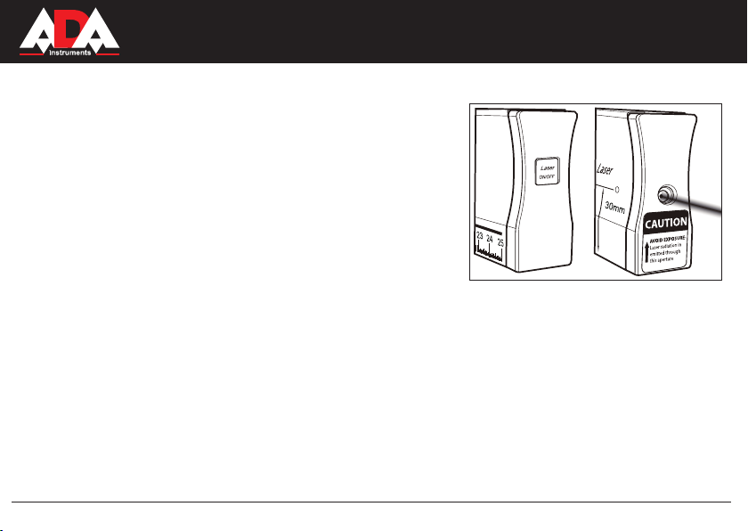
Laser alignment (Fig.10)
This digital level contains a laser diode located inside the left endcap
of the level. It provides a bright 635-665 nanometer beam with a useful
visibility that extends up to 50m indoors or outdoors (This range is only
applicable at night or dark environment.)
To activate the laser dot, press in the Laser ON/OFF button located
•
on the right endcap of the level
The center of the laser beam is 30mm above the bottom (working)
•
surface of the level.
Remember to account for this when doing layouts and taking mea-
•
surements.
Level the work surface, and the laser will project the level up to 50m
•
away to enable you to level large areas.
The laser projects a round dot on the targeted surface. The dot size
•
and shape may change slightly with distance, temperature or target
surface material. The point to use is the center of the dot pattern.
Operation with tripod (Figs.11,12 and 13)
This level can be used with a tripod to project a beam for up to 50m away. This feature is perfect for home improvement
projects such as aligning pictures, chair rails and other wall xtures, plumbing runs, and many other uses.
Adjust the tripod to true level, using the bubble vial on the base of the tripod.
•
Screw the level to the tripod using the 1/4-in. threaded hole located in the center of the working surface of the level
•
(see Fig. 11).
Adjust the height of the laser line you want to project.
•
Make any nal adjustments to tripod and level to nd the true level point. This will be
•
at 0.00° on the LCD display screen and, if activated, the beeper will beep.
Fig.10
14
MEASUREMENT FOUNDATION
Page 15

ProDigit 60
Fig.11
Fig.12
The laser projects a dot on the targeted surface (see Fig. 13) and the size and shape may vary according to tempera-
•
ture, distance and target surface material. ALWAYS use the center point of the dot for your measurement. Rotate the
level on the tripod to align chair rail, pictures, etc. 360° around the space.
Fig.11
15
Fig.12
Fig.13
MEASUREMENT FOUNDATION
Page 16

ProDigit 60
Current reading memorize button and memory recall
To save the information of the current reading, press the M button. The level can save nine different readings in its memory.
To read out the measurements, press the MR button. The last nine measurements can be read out, beginning with the most
recently saved. To make a new measurement, press the M button to return to measuring mode.
Using conversion button to change display units
The conversion button changes the measurement units from degrees (°) to pitch (in/ft) to slope percent (%). Pitch readings
are in 1/8-in. per foot increments. Plus and minus signs indicate when the pitch is slightly more (+) or less (-) than true
level shown on the display. The conversion button can be used even when the display is in the MR mode. This feature is a
convenient way to convert angles from one unit to another, For example, a 5-in/ft. roof pitch measurement can be converted
to 22.6° for setting up cuts on a chop saw.
Absolute angle and relative angle measurements
Absolute angle measurement
Lay the digital level on a working surface with the base at against the surface.
When level power is turned on, the display indicates the absolute angle between “level” and working surface. The zero line
indicates the level position, and the arrow indicates the direction of the working surface either above or below level.
To activate the beeper, push the beeper button. The beeper will sound when the level is at 0° (level), 45°, 90° (plumb) and
last saved angle. To deactivate beeper, push button a second time.
To save the measured angle in memory, press the M button. This level can remember the last nine measurements. To display the data in memory, press the memory recall button to recall recorded angles. The level will read out the data starting
with the most recent measurements and going backwards to the earliest in its memory.
To take a new measurement, press the hold button to return to measurement mode.
Relative angle measurement
Lay the digital level on the First working surface.
16
MEASUREMENT FOUNDATION
Page 17

ProDigit 60
Turn on the level. The LCD screen indicates the absolute angle between true level and the working surface.
Press the REF button to enter relative angle measurement mode. The current angle will be considered to be 0.0° and the
display will read 0.0°.
Place the digital level on the Second working surface and the relative angle between the First working surface and the
Second working surface will be displayed. The zero line indicates the First working surface position, and the arrow indicates
the direction
of the Second working surface either above or below the First working surface level.
At this point you can change the display units for the measured angle from degrees (°) to pitch (inch/foot) or slope (%) by
pressing the conversion button.
Maintenance
This digital laser level has been designed to be a low-maintenance tool. However, in order to maintain its performance,
follow these steps.
HANDLE the tool with care. Treat it as a precision optical device, such as a camera or binoculars.
•
11. AVOID exposing the tool to shock, continuous vibration or extreme hot or cold temperatures.
•
STORE the tool indoors and in a safe place.
•
The Level is designed to be weather resistant and construction site tough. If the level is splashed with mortar or other
•
construction site residue, simply wipe clean with a damp cloth. DO NOT immerse the level in water.
Aluminum surfaces can be cleaned with a non-abrasive powder.
•
Check the batteries regularly to avoid corrosion. REMOVE the batteries from the tool if it is not going to be used for
•
an extended period.
DO NOT try to take the level apart.
•
17
MEASUREMENT FOUNDATION
Page 18

Troubleshooting
Problem Cause Solution
La ser poi n t pr oje cti o n is
weak
Batteries are low voltage. Replace with new batteries
Laser point is not projected •Laser on/off button is not in
ON position.
•Batteries are installed
incorrectly.
•Battery power is low.
•Laser diode is damaged
•Check to make sure the switch
is in On position.
•Re-install batteries with correct
polarity.
•Replace with new batteries
•Take tool to the service center.
The LCD screen can not be
turned on
•Batteries are installed
incorrectly.
•Batteries voltage is low
•The LCD screen is damaged
•Re-install batteries with correct
polarity
•Replace with new batteries.
•Take tool to the service center.
dot line displayed on screen
ins tead of angl e, slope or
pitch
The di g i t a l le v e l is be ve l
pos it io ne d with the work in g
surface.
Mak e sure the digit al le vel is
positioned plumb to the working
surface.
Err oc curs on LC D durin g
calibration
•The gradien t of the working
surface for calibration exceeds
5 degree
•T he di g ita l lev e l is be vel
pos it io ne d with the work in g
surface.
•T he digit al lev el is mov ed
during the calibration
•Make sure the digi tal level is
pos ition ed on a leve l surfa ce
w i t h gr ad ie nt l e s s th a n 5
degree.
•Make sure the digi tal level is
positioned plumb to the working
surface
•Keep the level unmoved during
calibration.
Wro ng se tt ing the curre nt
angle to 0.00°
The digital level is not rotat e
18 0 ° be for e sta rti n g CA L2
during the calibration.
Re-calibrate the digital level with
a right procedure.
ProDigit 60
18
MEASUREMENT FOUNDATION
Page 19

ProDigit 60
Specic reasons for erroneous measuring results
Measurements through glass or plastic windows;
•
Dirty laser emitting window;
•
After instrument has been dropped or hit. Please check the accuracy.
•
Large uctuation of temperature: if instrument will be used in cold areas after it has been stored in warm areas (or the
•
other way round) please wait some minutes before carrying out measurements.
Electromagnetic acceptability (EMC)
It cannot be completely excluded that this instrument will disturb other instruments (e.g. navigation systems);
•
will be disturbed by other instruments (e.g. intensive electromagnetic radiation nearby industrial facilities or radio trans-
•
mitters).
19
MEASUREMENT FOUNDATION
Page 20

ProDigit 60
Laser classication
The instrument is a laser class 2 laser product accortding to DIN IEC 60825-1:2007. It is allowed to use unit without
further safety precautions.
Warranty
This product is warranted by the manufacturer to the original purchaser to be free from defects in material and workmanship under normal use for a period of two (2) years from the date of purchase.
During the warranty period, and upon proof of purchase, the product will be repaired or replaced (with the same or
similar model at manufactures option), without charge for either parts of labour.
In case of a defect please contact the dealer where you originally purchased this product. The warranty will not apply
to this product if it has been misused, abused or altered. Withiut limiting the foregoing, leakage of the battery, bending
or dropping the unit are presumed to be defects resulting from misuse or abuse.
20
MEASUREMENT FOUNDATION
Page 21

ProDigit 60
Exceptions from responsibility
The user of this product is expected to follow the instructions given in operators’ manual.
Although all instruments left our warehouse in perfect condition and adjustment the user is expected to carry out periodic
checks of the product’s accuracy and general performance.
The manufacturer, or its representatives, assumes no responsibility of results of a faulty or intentional usage or misuse includ-
ing any direct, indirect, consequential damage, and loss of prots.
The manufacturer, or its representatives, assumes no responsibility for consequential damage, and loss of prots by any
disaster (earthquake, storm, ood ...), re, accident, or an act of a third party and/or a usage in other than usual conditions.
The manufacturer, or its representatives, assumes no responsibility for any damage, and loss of prots due to a change of
data, loss of data and interruption of business etc., caused by using the product or an unusable product.
The manufacturer, or its representatives, assumes no responsibility for any damage, and loss of prots caused by usage other
thsn explained in the users’ manual.
The manufacturer, or its representatives, assumes no responsibility for damage caused by wrong movement or action due to
connecting with other products.
21
MEASUREMENT FOUNDATION
Page 22

WARRANTY DOESN’T EXTEND TO FOLLOWING CASES:
1. If the standard or serial product number will be changed, erased, removed or wil be unreadable.
2. Periodic maintenance, repair or changing parts as a result of their normal runout.
3. All adaptations and modications with the purpose of improvement and expansion of normal sphere of product application, mentioned in the service instruction, without tentative written agreement of the expert provider.
4. Service by anyone other than an authorized service center.
5. Damage to products or parts caused by misuse, including, without limitation, misapplication or nrgligence of the terms
of service instruction.
6. Power supply units, chargers, accessories, wearing parts.
7. Products, damaged from mishandling, faulty adjustment, maintenance with low-quality and non-standard materials,
presence of any liquids and foreign objects inside the product.
8. Acts of God and/or actions of third persons.
9. In case of unwarranted repair till the end of warranty period because of damages during the operation of the product,
it’s transportation and storing, warranty doesn’t resume.
For more information you can visit our website WWW.ADAINSTRUMENTS.COM
or write the letter with your questions on info@adainstruments.com
Page 23

WARRANTY CARD
Name and model of the product ________________________________________________
Serial number ________________date of sale_______________________
Name of commercial organization _____________________stamp of commercial organization
Warranty period for the instrument explotation is 24 months after the date of original retail purchase. It extends to the equipment, imported
on the RF territory by ofcial importer.
During this warranty period the owner of the product has the right for free repair of his instrument in case of manufacturing defects.
Warranty is valid only with original warranty card, fully and clear lled (stamp or mark of thr seller is obligatory).
Technical examination of instruments for fault identication which is under the warranty, is made only in the authorized service center.
In no event shall manufacturer be liable before the client for direct or consewuential damages, loss of prot or any other damage which
occur in the result of the instrument outage.
The product is received in the state of operability, without any visible damages, in full completeness. It is tested in my presence. I have no
complaints to the product quality. I am familiar with the conditions of qarranty service and i agree.
purchaser signature _______________________________
If you have any questions about the warranty service and technical support contact seller of this product
Before operating you should read service instruction!
Page 24

Certicate of acceptance and sale
__________________________________________________________________________
__________________________________________________________________________
___________________________________________________________№_____________
name and model of the instrument
Corresponds to ______________________________________________________________
designation of standard and technical requirements
Data of issue _______________________________________________________________
Stamp of quality control department
Price
Sold ___________________________________ Date of sale ______________________
name of commercial establishment
Page 25

Руководство по эксплуатации
Электронный уровень
Модель: ProDigit 60
Производитель: ADAINSTRUMENTS Адрес: WWW.ADAINSTRUMENTS.COM
Page 26

ProDigit 60
Оглавление
1. Приедупреждающие символы . . . . . . . . . . . . . . . . . . . . . . . . . . . . . . . . . . . . . . . . . . . . . . . . . . . .27
2. Меры предосторожности . . . . . . . . . . . . . . . . . . . . . . . . . . . . . . . . . . . . . . . . . . . . . . . . . . . . . . .28
3. Описание прибора . . . . . . . . . . . . . . . . . . . . . . . . . . . . . . . . . . . . . . . . . . . . . . . . . . . . . . . . . . 30
4. Технические характеристики . . . . . . . . . . . . . . . . . . . . . . . . . . . . . . . . . . . . . . . . . . . . . . . . . . . . 33
5. Калибровка электронного уровня . . . . . . . . . . . . . . . . . . . . . . . . . . . . . . . . . . . . . . . . . . . . . . . . . . . 35
6. Измерения . . . . . . . . . . . . . . . . . . . . . . . . . . . . . . . . . . . . . . . . . . . . . . . . . . . . . . . . . . . . . . . 36
7. Техническое обслуживание и указания . . . . . . . . . . . . . . . . . . . . . . . . . . . . . . . . . . . . . . . . . . . . . . .41
8. Особые случаи получения неверных результатов измерения . . . . . . . . . . . . . . . . . . . . . . . . . . . . . . . . . . . 42
9. Электромагнитная совместимость . . . . . . . . . . . . . . . . . . . . . . . . . . . . . . . . . . . . . . . . . . . . . . . . . . 42
10. Класссификация лазера . . . . . . . . . . . . . . . . . . . . . . . . . . . . . . . . . . . . . . . . . . . . . . . . . . . . 42
11. Устранение неполадок . . . . . . . . . . . . . . . . . . . . . . . . . . . . . . . . . . . . . . . . . . . . . . . . . . . . . . . 43
12. Гарантия . . . . . . . . . . . . . . . . . . . . . . . . . . . . . . . . . . . . . . . . . . . . . . . . . . . . . . . . . . . . . . . 44
13. Освобождение от ответственности . . . . . . . . . . . . . . . . . . . . . . . . . . . . . . . . . . . . . . . . . . . . . . . . .45
14. Приложение 1 - “Свидетельство о приемке и продаже”
15. Приложение 2 - “Гарантийный талон”
Page 27

ProDigit 60
Предупреждающие символы
Главная задача предупреждающих символов - привлечь ваше внимание к возможной проблеме. Необходимо
внимательно прочитать символы безопасности и их объяснения. Сами по себе, предупредительные символы не
устраняют опасность.
Предупреждение: Перед тем, как приступить к работе с электронным уровнем, внимательно прочитайте инструкцию
по безопасности в данном руководстве, а также ознакомьтесь со всеми предупредительными символами, такими как
“DANGER”, “WARNING”, “CAUTION” (“Опасность”, “Осторожно”, “Внимание”).
Пренебрежение всеми перечисленными ниже инструкциями может привести к поражению электрическим током, пожару
и/или серьезному телесному повреждению.
Значение предупреждающих символов
Предупреждающие символы Опасность, Осторожно, Внимание могут использоваться с другими символами или
пиктограмами.
Пренебрежительное отношение к предупреждающим символам может привести к СЕРЬЕЗНОЙ ТРАВМЕ. Всегда
следуйте мерам предосторожности, благодаря которым уменьшается риск возникновения пожара, электрического
удара или получения травм.
Информационные сообщения
Эти сообщения информируют пользователя о важной информации и/или содержат инструкции, которые, если им не
следовать, могут привести к повреждению оборудования или имущества. Каждое сообщение начинается со слова
“Внимание”, например:
Внимание: пренебрежительное отношение к данным инструкциям может привести к повреждению оборудования и/или
имущества.
27
MEASUREMENT FOUNDATION
Page 28

ProDigit 60
Меры предосторожности
Осторожно: Перед тем, как приступить к работе с электронным уровнем, внимательно прочитайте инструкцию по
безопасности в данном руководстве. Пренебрежение всеми перечисленными инструкциями может привести к
радиоактивному облучению, электрическому удару, пожару и/или серьезному телесному повреждению.
Правила безопасности при работе с лазерным уровнем:
Осторожно: использование иных средств управлений и настроек может привести к опасному радиоактивному
облучению.
Осторожно: Использование таких оптических приборов как телескопы или теодолиты, для того, чтобы увидеть
лазерный луч, увеличивает опасность для глаз.
Данный уровень содержит встроенный лазерный луч. Лазер класса 2 излучает энергию макс. 1 mW и имеет длину
волны 635-665 nm. Не смотрите на луч!
Внимание: данная наклейка находится на вашем приборе. Этот предупредительный символ сообщает о том, что
уровень излучает лазерный луч. БУДЬТЕ ОСТОРОЖНЫ. Все посторонние наблюдатели должны быть предупреждены
о том, что на луч смотреть нельзя.
Осторожно: ЛАЗЕРНОЕ ИЗЛУЧЕНИЕ. НЕ смотрите на луч. Включайте лазерный луч только тогда, когда вы готовы
приступить к работе.
1)НЕ удаляйте и не стирайте предупредительные наклейки.
Удаление предупредительных наклеек повышает риск воздействия лазерного облучения.
28
MEASUREMENT FOUNDATION
Page 29

ProDigit 60
2) НЕ смотрите прямо на луч и не направляйте луч в глаза других людей. Это может привести к повреждению
глаз.
3) НЕ ставьте лазерный уровень на уровне глаз. Это может привести к повреждению глаз.
4) НЕ используйте никакие оптические инструменты (теодолиты, телескопы) для лучшего видения лазерного
луча. Это может привести к повреждению глаз.
5) Не включайте прибор, когда рядом находятся дети. Не позволяйте детям включать прибор. Это может
привести к повреждению глаз.
6) ВСЕГДА выключайте лазерный уровень, когда вы его не используете. Иначе кто-нибудь может случайно
посмотреть на лазерный луч.
7) НЕ включайте лазерный уровень, если рядом находятся воспламеняющиеся жидкости, газ или пыль.
8) НЕ ставьте прибор на отражающую поверхность, например, на стальной лист. Яркая поверхность может
отразить луч обратно на человека. Будьте внимательны, лазерный луч, отраженный от зеркала или других
отражающих поверхностях, может быть опасным.
9) НЕ используйте прибор не по назначению. Это может привести к серьезному повреждению.
10) ВСЕГДА используйте 2 батареи типа “ААА”. Правильно вставьте батареи, соблюдайте полярность.
11) НЕ используйте новую батарею со старой. Батареи должны соответствовать по типу и марке.
12) Выбрасывайте старые батарейки.
13) НИКОГДА не кидайте батарейки в огонь.
14) Не давайте батарейки детям. Это не игрушка.
15) Вынимайте батарейки из батарейного отсека, если вы не используете прибор несколько дней.
16) Не пытайтесь починить или разобрать лазерный уровень. Техническое обслуживание и ремонт цифрового
уровня должны проводиться в авторизованном сервисном центре.
29
MEASUREMENT FOUNDATION
Page 30

ProDigit 60
Описание прибора
Замечание: Перед тем, как приступить к работе с прибором, ознакомьтесь с требованиями по безопасности и правилами
пользования.
Электронный уровень- это легкий прибор из алюминия с цифровым ЖК дисплеем, с помощью которого вы можете
производить угловые измерения, такие как уклон ската крыши и угол среза и т.д.
Используйте лазерный луч для визуального увеличения линии уровня на больших расстояниях.
При выполнении работ, держите прибор в руках или поместите его на штатив.
Электронный уровень подходит для работ внутри и снаружи помещения.
Измерение углов с точностью до 0.05°.
Измеряет любые наклоны в процентах, позволяет определить положение горизонтальной и вертикальной плоскостей
с помощью ЖК дисплея или с помощью вертикального или горизонтального пузырьковых уровней.
Схема прибора:
1) Клавишная панель
2) ЖК дисплей- большой, легко-читаемый экран воспроизводит результаты измерений даже в том случае, если
прибор перевернут.
3) Пузырьковые уровни- с помощью пузырьковых уровней вы можете точно установить электронный уровень
в горизонтальном и вертикальном положении. Высокочувствительный пузырьковый уровень обеспечивает
точность измерения в 0.029°.
4) Встроенная Линейка, 57 см.
5) Кнопка ВКЛ/ВЫКЛ лазера- расположена с права на крышке электронного уровня.
6) Крышки прибора- крышки уровня защищают прибор от повреждений.
7) Апертура лазера- лазерный излучатель расположен на левой стороне крышки прибора.
30
MEASUREMENT FOUNDATION
Page 31

ProDigit 60
2
1
3
4
3
9
10
11
12
8
5
6
8
8) Магнитное основание- 4 магнита на рабочем основании для крепления на металле.
9) Резьба под штатив 1/4”- уровень можно поместить на штатив, продается отдельно.
10) Рабочее основание- рабочее основание должно прочно лежать на поверхности. Рабочее основание
разработано для плоских поверхностей, а V-образное углубление используется при работе с круглыми
предметами, например, трубой.
11) Батарейный отсек- вмещает две батареи “ААА” для работы лазера и ЖК дисплея.
12) Большие и удобные ручки- облегчают работу и транспортировку прибора.
31
Рис. 1a
MEASUREMENT FOUNDATION
Page 32
ProDigit 60
Функции кнопок (Рис.1b)
1) Кнопка ВКЛ/ВЫКЛ прибора - нажмите на кнопку для того, чтобы включить электронный уровень.
Длительное нажатие на кнопку выключает прибор.
2) Кнопка REF- нажмите на кнопку для начала калибровки. Нажмите на кнопку и удерживайте ее в течение 3
сек, чтобы начать калибровку.
3) Звук ВКЛ/ВЫКЛ - кнопка для активирования сигнала. Для отключения сигнала нажмите на кнопку еще
раз.
4) Кнопка М- нажмите на кнопку для сохранения в памяти текущего измерения (электронный уровень позволяет
сохранить в памяти 9 значений).
5) Кнопка MR- нажмите на эту кнопку, чтобы обратиться к последним 9 измерениям, которые сохранены в
памяти. Последнее измерение будет воспроизводиться первым.
6) Кнопка UNIT- с помощью этой кнопки вы можете менять единицы измерения: градусы (°), дюймы/футы,
проценты (%). Знаки плюс и минуc обозначают положение угла наклона измеренной плоскости относительно
горизонта.
32
MEASUREMENT FOUNDATION
Page 33

ProDigit 60
Иконки на ЖК дисплее
0
Индикатор Вверх/Вниз- нулевая линия (0°) обозначает положение уровня. Стрелка обозначает положение текущего
угла, выше оно или ниже уровня (0°).
Иконка состояния батареи- обозначает состояние батареи. Замените батарейки, когда появится черный штрих.
Иконка звукового сигнала- иконка появляется на экране, когда активируется звуковой сигнал.
Иконка памяти- эта иконка появляется тогда, когда используется функция памяти. Электронный уровень
М1-М9
сохраняет 9 последних измерений.
REF
Обозначает, что уровень работает в режиме измерения относительного угла.
Err
Обозначает, что уровень неправильно установлен или неправильно проведена калибровка.
CAL1
Обозначает, что уровень калибруется в одном направлении (см.режим калибровки).
CAL2
Обозначает, что уровень калибруется в другом направлении (см. режим калибровки).
Технические характеристики
Применение внутри помещения и на улице
Класс лазера класс 2, макс. выход лазера �1mW�1mW
Источник питания 2 х 1.5 V ААА батарейки
Диапазон углового измерения 0-360°
Оптимальный диапазон работы 0-40°
Точность пузырьковых уровней ±0.029°
Точность цифрового уровня ±0.05° (горизонт. или вертикал.)
Продолжительность работы
цифрового уровня
±0.1° (другие углы)
10 часов с щелочными батарейками.
33
MEASUREMENT FOUNDATION
Page 34

ProDigit 60
+
-
Для работы многофункционального электронного уровня необходимо 2 батареи “ААА”.
Замечание: Перед тем, как вставить батареи, убедитесь, что прибор выключен.
Рис.2
1) Откройте крышку батарейного отсека, которая расположена с обратной стороны электронного уровня
(Рис.2).
2) Вставьте две новые батареи типа “ААА”, соблюдайте полярность (+/-).
3) Закройте крышку батарейного отсека.
Нажмите на кнопку включения для включения ЖК дисплея. При включении дисплея, на экране появится на 2 сек
показание температуры, которое сообщает о том, используется ли уровень в оптимальном температурном диапазоне.
Затем отображается текущий угол уровня и показывается изображение этого угла выше или ниже уровня горизонта.
Стрелка на дисплее указывает на то, что уровень надо опустить или поднять. Точное положение достигается только в
том случае, если две линии находятся вместе и угол показывает 0.00°.
Для выключения ЖК дисплея нажмите и удерживайте в течение 2-х сек кнопку включения прибора. Если устройство не
используется в течение 5 мин, уровень
34
MEASUREMENT FOUNDATION
Page 35

ProDigit 60
выключается автоматически. ЖК дисплей большой и легко читаемый. Когда вы переворачиваете прибор, дисплей
переворачивает изображение значений.
Калибровка электронного уровня (рис.3, 4)
1) Поместите уровень на плоскую ровную поверхность, нажмите и удерживайте около 3 сек кнопку REF, функция
калибровки активируется. На экране будет мигать “CAL1”.
2) Не двигайте прибор несколько секунд, пока не услышите звуковой сигнал, затем на экране появится “CAL2”.
3) Поверните прибор на 180° в этом же положении, затем нажмите кнопку REF, на экране начнет мигать “CAL2”,
не двигайте прибор несколько секунд, затем в течении 2 сек будет раздаваться звуковой сигнал, который
говорит о том, что калибровка завершена. На дисплее появится значение текущего угла.
Рис.3 Рис.4
Важное замечание:
Калибруйте инструмент каждый раз перед его использованием.
•
Для получения точного измерения необходимо калибровать инструмент отдельно: для горизонтального измерения,
•
вертикального измерения.
Калибровку необходимо производить на плоской и ровной поверхности с отклонением от горизонта не более чем 5°.
•
Если отклонение больше 5°, в течение трех секунд будет раздаваться сигнал, на дисплее появится “Err”-это значит,
что калибровка не была произведена.
Во время калибровки уровень должен оставаться неподвижным, в противном случае на дисплее появится “Err”.
•
После того, как CAL1 завершена, уровень необходимо повернуть на 180°, чтобы начать CAL2. Если вы оставите
•
прибор неподвижным и начнете CAL2, текущая рабочая поверхность отобразится на дисплее как 0°. Измерение
глов с точностью 0.05° доступно только после переключения на градусы или % и отклонение должно быть не
больше 1°. Если отклонение больше 1°, цифровой уровень работает с точностью 0.1°.
35
MEASUREMENT FOUNDATION
Page 36

ProDigit 60
Измерения
Горизонтальные и вертикальные измерения
При проведении горизонтальных и вертикальных измерениях можно использовать как пузырьковый уровень, так и
показания ЖК дисплея.
Горизонтальное измерение (Рис.5)
Положите уровень на горизонтальную поверхность. Пузырьки будут точно между отметками на ампуле.
Нажмите кнопку включения цифрового уровня и положите прибор на поверхность.
На ЖК дисплее отобразятся поверхность в виде линии, которая может быть выше или ниже линии уровня, и градусы,
которые показывают наклон поверхности.
Рис.5
Стрелка указывает направление, в котором следует поднять или опустить поверхность. Для
выравнивания, двигайте поверхность с уровнем, пока две линии на дисплее не совпадут и не
появится угол 0.00°. Если у вас включен звук, раздастся звуковой сигнал.
Вертикальное измерение (Рис.6)
Прислоните прибор к вертикальной поверхности так, чтобы вертикальный пузырьковый уровень
был на верху. Вертикальная поверхность будет считаться ровной только тогда, когда пузырек будет
располагаться между отметками на ампуле.
На дисплее поверхность будет отображена в виде линии которая может находиться левее или правее
линии уровня. Стрелка указывает направление, в котором следует подвинуть поверхность вправо
или влево. Раздастся звуковой сигнал (если звук включен), когда на дисплее появится значение
90.00°.
36
MEASUREMENT FOUNDATION
Рис.6
Page 37
Уклон ската крыши (Рис.7)
Электронный уровень может применяться для измерения уклона ската крыши.
Прибор измеряет уклон в градусах; %; дюймах на на футы.
Рис.7
Измерение угла (Рис.8)
Электронный уровень измеряет любой угол в градусах с точностью до 0.1°, на
горизонтальной или вертикальной поверхностях точность будет до 0.05°.
Это может пригодиться для нахождения необходимого угла для нескольких
поверхностей. При угле 0.00° прозвучит звуковой сигнал.
Рис.8
Измерение наклона (Рис.9)
Электронный уровень измеряет наклон поверхности в процентах. Это необходимо
при укладке труб. Когда прибор установлен в режим наклона, на дисплее отобразится
измеренная поверхность в процентах, с точным уровнем 0.00%. Звуковой сигнал
прозвучит при 0.00%.
Рис.9
ProDigit 60
37
MEASUREMENT FOUNDATION
Page 38
ProDigit 60
Выравнивание лазера (Рис.10)
В цифровой уровень встроен лазерный излучатель. Он находится внутри
под крышкой с левой стороны прибора. Диапазон работы лазерного луча
составляет 50м внутри помещения и на улице (в ночных условиях или в
сумерках).
1) Для включения лазерного излучателя, нажмите на кнопку ВКЛ/ВЫКЛ
прибора, которая находится на крышке с правой стороны уровня.
2) Лазерный излучатель находится в 30 мм от края рабочей поверхности
уровня.
3) Выставьте электронный уровень горизонтально и диапазон работы
с лазерным лучом будет составлять 50 м, что позволит вам работать на
больших площадях.
4) Лазерный излучатель проецирует круглую точку на заданную
поверхность. Размер точки и ее форма могут слегка меняться в
зависимости от расстояния, температуры или материала заданной
поверхности.
Рис.10
Использование электронного уровня на штативе (Рис. 11, 12 и 13)
Установите электронный уровень на штатив. Благодаря этому вы без труда ровно повесите картины, проложите трубы
и т.д.
1)Установите штатив ровно при помощи пузырькового уровня на основании штатива.
2) Установите уровень на штатив при помощи отверстия под штатив 1/4”, расположенного в центре рабочей поверхности
уровня (смотрите рис.11).
3) Отрегулируйте высоту лазерного луча.
4) Установите штатив и уровень горизонтально. На ЖК дисплее будет значение 0.00° и раздастся звуковой сигнал.
38
MEASUREMENT FOUNDATION
Page 39

ProDigit 60
Fig.11
Fig.12
5) Лазерный излучатель спроецирует точку на заданную поверхность (см. рис.13). Размер и форма лазерной точки будет
зависеть от температуры, расстояния и материала заданной поверхности.
Рис.11
39
Рис.12
Рис.13
MEASUREMENT FOUNDATION
Page 40

ProDigit 60
Запоминание значения текущего измерения и активизации памяти
Чтобы сохранить значение текущего измерения, нажмите на кнопку М. Электронный уровень может сохранить
9 разных измерений. Для обращения к сохраненным значениям измерений, нажмите кнопку MR. Последнее сохраненное
измерение будет отображаться первым. Для возвращения в режим измерения нажмите кнопку М.
Кнопка UNIT
С помощью этой кнопки вы можете менять единицы измерения: градусы (°), дюймы/футы, проценты (%). Знаки плюс и
минус обозначают, что угол наклона “больше” (+) или “меньше” (-), чем горизонтальный уровень. Вы можете использовать
эту кнопку, даже если уровень работает в режиме MR. С помощью этой функции вы можете легко менять единицы
измерения угла. Например, измерение уклона ската крыши 5 дюймов/фут можно преобразовать в градусы- 22.6°.
Измерения абсолютного и относительного угла.
Bзмерение абсолютного угла
1)Положите электронный уровень рабочим основанием на поверхность.
2)После того, как вы включите прибор, на дисплее отобразится угол между горизонтальным “уровнем” и рабочей
поверхностью. Нулевая линия обозначает горизонтальное положение уровня, а стрелка указывает выше или ниже
рабочей поверхности горизонтальный уровень.
3)Включите звук. Звуковой сигнал сработает, когда значение уровня будет 0° (горизонт.), 45°, 90° (вертик.) и при
отображении последнего сохраненного значения угла.
4)Чтобы сохранить информацию о текущем измерении, нажмите на кнопку М. В своей памяти уровень сохраняет 9
разных измерений. Для обращения к сохраненным измерениям, нажмите кнопку MR. Последнее измерение будет
отображаться первым.
5)Для возвращения в режим измерения нажмите кнопку М.
Измерение относительного угла
1)Положите электронный уровень на Первую рабочую поверхность.
40
MEASUREMENT FOUNDATION
Page 41

ProDigit 60
2) Включите уровень. На дисплее отобразится угол между уровнем и рабочей поверхностью.
3) Нажмите кнопку REF, чтобы войти в режим измерения относительного угла. Значение текущего угла будет считаться
0.0°.
4) Положите уровень на Вторую рабочую поверхность. На дисплее отобразится относительный угол между Первой и
Второй рабочими поверхностями. Нулевая линия означает положение Первой рабочей поверхности, стрелка означает
направление Второй рабочей поверхности, которая либо выше либо ниже Первой рабочей поверхности.
5) Теперь вы можете изменить режим измерений для измеренного угла при помощи нажати кнопки UNIT.
Техническое обслуживание и указания
Не смотреть на лазерный луч- не направлять лазерный инструмент на людей!
•
Не использовать прибор в дождь!
•
Транспортировать только в специальной сумке. При этом убедиться, что прибор выключен!
•
Протирать лазерный инструмент, и особенно окошко лазерного луча, мягкой тряпкой!
•
Перед важными замерами и в определенных случаях проверять регулировку!
•
Не срывайте с прибора предупредительные этикетки и правила техники безопасности!
•
Не вскрывайте корпус прибора!
•
Используйте прибор только для измерительных работ!
•
Ремонт прибора следует проводить только в
•
Просьба обращаться в торговое представительство!
•
Не допускайте детей до прибора!
•
Не используйте прибор во взрывоопасной атмосфере!
•
сертифицированной мастерской.
41
MEASUREMENT FOUNDATION
Page 42

ProDigit 60
Особые случаи получения неверных результатов измерений
Измерение через стеклянные или пластмассовые окна.
•
Грязь на окнах, через которые проходит лазерный луч.
•
Измерение после того, как прибор уронили или ударили (необходимо проверить точность прибора!).
•
Большие колебания температуры. Если лазерный построитель, находящийся в теплом помещении, будет
•
использоваться в холодном (и наоборот), убедительная просьба подождать несколько минут, прежде чем
проводить измерения!
Электромагнитная совместимость (ЕМС)
Не исключено, что работа лазерного построителя плоскостей может повлиять на работу других
•
устройств (например, системы навигации);
На работу лазерного построителя плоскостей может повлиять работа других приборов (например,
•
интенсивное электромагнитное излучение от промышленного оборудования или радиоприборов).
Классификация лазера
Данный прибор является лазером класса 2 в соответствии с DIN IEC 60825-1:2007, что позволяет использовать устройство
выполняя меры предосторожности (см. ниже).
42
MEASUREMENT FOUNDATION
Page 43

Устранение неполадок
Проблема Причина Решение
Слабое проецирование
лазерной точки
Лазерный луч не
проецируется
ЖК дисплей не
включается
Вместо угла, наклона
или уклона на экране
отображается _ _ _.
Батареи разряжены Замените батареи на новые
- Не активирована
кнопка ВКЛ/ВЫКЛ
лазерного луча.
- Неправильно
вставлены батареи.
- низкий заряд батареи
- поврежден лазерный
диод
-Неправильно
вставлены батареи.
-низкий заряд батареи
- ЖК дисплей
поврежден
Некорректно установлен
уровень
-убедитесь, что переключатель
находится в положении ON.
-Переустановите батареи,
соблюдайте полярность.
-Замените батареи на новые.
-Сдайте прибор в сервисный
центр
-Переустановите батареи,
соблюдайте полярность.
- Замените батареи на новые.
- Сдайте прибор в сервисный
центр
Убедитесь, что электронный
уровень расположен
вертикально к рабочей
поверхности.
ProDigit 60
43
MEASUREMENT FOUNDATION
Page 44

ProDigit 60
Гарантия
Производитель предоставляет гарантию на продукцию покупателю в случае дефектов материала или качества его
изготовления во время использования оборудования с соблюдением инструкции пользователя на срок до 1 года со дня
покупки.
Во время гарантийного срока, при предъявлении доказательства покупки, прибор будет починен или заменен на такую
же или аналогичную модель бесплатно. Гарантийные обязательства также распространяются и на запасные части.
В случае дефекта, пожалуйста, свяжитесь с дилером, у которого вы приобрели прибор. Гарантия не распространяется
на продукт, если повреждения возникли в результате деформации, неправильного использования или ненадлежащего
обращения.
Все вышеизложенные безо всяких ограничений причины, а также утечка батареи, деформация прибора являются
дефектами, которые возникли в результате неправильного использования или плохого обращения.
Освобождение от ответственности
Пользователю данного продукта необходимо следовать инструкциям, которые приведены в руководстве по эксплуатации.
Даже, несмотря на то, что все прборы проверены производителем, пользователь должен проверять точность прибора
и его работу.
Производитель или его представители не несут ответственности за прямые или косвенные убытки, упущенную выгоду
или иной ущерб, возникший в результате неправильного обращения с прибором.
Производитель или его представители не несут ответственности за косвенные убытки, упущенную выгоду, возникшие в
результате катастроф (землетрясение, шторм, наводнение и т.д.), пожара, несчастных случаев, действия третьих лиц
и/или использование прибора в необычных условиях.
Производитель или его представители не несут ответственности за косвенные убытки, упущенную выгоду, возникшие
в результате изменения данных, потери данных и временной приостановки бизнеса и т.д., вызванных применением
прибора.
Производитель или его представители не несут ответственности за косвенные убытки, упущенную выгоду, возникшие в
результате использования прибора не по инструкции.
44
MEASUREMENT FOUNDATION
Page 45

ГАРАНТИЙНЫЕ ОБЯЗАТЕЛЬСТВА НЕ РАСПРОСТРАНЯЮТСЯ НА СЛЕДУЮЩИЕ СЛУЧАИ:
1.Если будет изменен, стерт, удален или будет неразборчив типовой или серийный номер на изделии;
2.Периодическое обслуживание и ремонт или замену запчастей в связи с их нормальным износом;
3.Любые адаптации и изменения с целью усовершенствования и расширения обычной сферы применения
изделия, указанной в инструкции по эксплуатации, без предварительного письменного соглашения специалиста
поставщика;
4.Ремонт, произведенный не уполномоченным на то сервисным центром;
5.Ущерб в результате неправильной эксплуатации, включая, но не ограничиваясь этим, следующее:
использовнаие изделия не по назначению или не в соответствии с инструкцией по эксплуатации на прибор;
6.На элементы питания, зарядные устройства, комплектующие, быстроизнашивающиеся и запасные части;
7. Изделия, поврежденные в результате небрежного отношения, неправильной регулировки, ненадлежащего
технического обслуживания с применением некачественных и нестандартных расходных материалов, попадания
жидкостей и посторонних предметов внутрь.
8.Воздействие факторов непреодолимой силы и/или действие третьих лиц;
9.В случае негарантийного ремонта прибора до окончания гарантийного срока, произошедшего по причине
полученных повреждений в ходе эксплуатации, транспортировки или хранения, и не возобновляется.
Для получения дополнительной информации Вы можете посетить наш Интернет сайт WWW.ADAINSTRUMENTS.COM
или написать письмо с интерисующими Вас вопросами на электронный адрес info@adainstruments.com
Page 46

ГАРАНТИЙНЫЙ ТАЛОН
Наименование изделия и модель _______________________________________________
Серийный номер ___________________Дата продажи_________________
Наименование торговой организации ___________________Штамп торговой организации мп.
Гарантийный срок эксплуатации приборов составляет 24 месяца со дня продажи и распространяется на
оборудование, ввезенное на территорию РФ официальным импортером.
В течении гарантийного срока владелец имеет право на бесплатный ремонт изделия по неисправностям,
являющимся следствием производственных дефектов.
Гарантийные обязательства действительны только по предъявлении оригинального талона, заполненного
полностью и четко (наличие печати и штампа с наименованием и формой собственности продавца
обязательно).
Техническое освидетельствование приборов (дефектация) на предмет установления гарантийного случая
производится только в авторизованной мастерской.
Производитель не несет ответственности перед клиентом за прямые или косвенные убытки, упущенную выгоду
или иной ущерб, возникшие в результате выхода из строя приобретенного оборудования.
Правовой основой настоящих гарантийных обязательств является действующее законодательство, в частности,
Федеральный закон РФ “О защите прав потребителя” и Гражданский кодекс РФ ч.II ст. 454-491.
Товар получен в исправном состоянии, без видимых повреждений, в полной комплектности, проверен в моем
присутствии, претензий по качеству товара не имею. С условиями гарантийного обслуживания ознакомлен и
согласен.
Подпись получателя_________________________________
Перед началом эксплуатации внимательно ознакомьтесь с инструкцией по эксплуатации!
По вопросам гарантийного обслуживания и технической поддержки обращаться к продавцу данного товара
Page 47

СВИДЕТЕЛЬСТВО О ПРИЕМКЕ И ПРОДАЖЕ
______________________________________________________________________________________________
______________________________________________________________________________________________
_____________________________________________________________________________№_______________
НАИМЕНОВАНИЕ И ТИП ПРИБОРА
Соответствует __________________________________________________________________________________
обозначение стандарта и технических условий
Дата выпуска ___________________________________________________________________________________
Штамп ОТК (клеймо приемщика)
Цена
Продан(а) ___________________________________________________Дата продажи ______________________
Page 48

MEASUREMENT FOUNDATION
WWW.ADAINSTRUMENTS.COM
ADA
 Loading...