

Page 1

Analytical Balance
Model
GR-120
GR-200
GR-300
GR-202
1563-2A-IE.1999.02.08
A&D Company Limifed
Page 2

A
This is an information mark that informs you about the operation of
the balance.
NOTE This manual and ortheGR series balances may be changed at any
time to improve the product without notice.
This is a hazard alert mark.
Page 3

Contents
Basic Operation
1. Introduction....................................................................................................... 3
Compliance with FCC Rules
Compliance with EMC Directives
2. Caution.............................................................................................................. 5
Precautions for Installing the Balance
Cautions during use (To get best performance)...................................... 6
Take Care of Your Balance..................................................................... 7
Power Supply............................................................................................... 7
3. Unpacking your balance...................................................................................... 8
Installing your Balance
Display Symbols and Key Operation........................................................... 9
4. Weighing Units.................................................................................................... 11
5. Weighing............................................................................................................. 13
Basic Operation (gram mode)
Counting Mode (pcs)
Percent Mode (%)
................................................................................
.....................................................................................
...................................................................
............................................................
........................................................
................................................................................
..................................................................
4
4
. 5
9
13
14
15
Adapting to the Environment
6. Response Adjustment......................................................................................... 16
Automatic Response Adjustment
Manual Response Adjustment
7. Calibration........................................................................................................... 18
Calibration Group
Automatic Self Calibration......................................................................... 19
Calibration Using the Internal Weight........................................................ 20
Calibration Test Using the Internal Weight
Calibration Using an External Weight........................................................ 22
Calibration Test Using an External Weight
Correcting the Internal Weight Value
......................................................................................
..............................................................
..................................................................
...............................................
.............................................
........................................................
Functions
8. Function Switch and Initialization........................................................................ 28
Permission or Prohibition
Initializing the Balance
9. Function Table.................................................................................................. 30
Display and Keys of the Function Table
Details of the Function Table
Explanation of Item "Environment, Display"............................................ 34
Explanation of Item "Data output mode"
Explanation of Item "Data format" ............................................................ 36
Examples of data format
.........................................................................
..............................................................................
...................................................
..................................................................
.................................................
...........................................................................
16
17
18
21
24
26
28
29
31
32
35
38
page 1 Contents
Page 4

1. Introduction
THANK YOU FOR YOUR A&D PURCHASE
This manual will tell you in simple language how this balance works and how
to get the most out of it in terms of performance.
Chapters of this book
Basic operation
Adapting to the environment... Explanations concerning response adjustment,
........................
Please read this chapter before use. cautions,
basic operation and names are described.
calibration and calibration test.
Functions
Serial interface (RS-232C)
Maintenance
.................................
......
............................
Functions and parameters for the balance.
This interface transmits data and can control the
balance.
Maintenance, error code list, options, terms and
index.
Features
□ Built-in Calibration Weight (internal weight), used to calibrate and verify the
calibration of your balance.
□ Automatic Self Calibration, using the built-in weight, adapting to changes in
temperature.
□ Automatic Response Adjustment, adapting to vibration and drafts in the
environment.
□ Data Memory Function, storing 200 weighing data.
□ Interval Memory Mode, storing weighing data periodically.
□ Good Laboratory Practices (GLP) data output using a serial interface.
□ Under Hook, for measuring specific gravity and magnetic substances.
□ The balance is equipped with the specific gravity measuring mode to
calculate the specific gravity (density) of a solid.
□ Multiple Weighing Units, with most of the common units used around the world.
□ RS-232C serial interface, for transmitting data and controlling your balance.
□ Door Control Lever, a front mounted door control can easily open and close
one of the side doors if connected using the door joint.
Basic operation page 3 1 ■ Introduction
Page 5

Compliance with FCC Rules
Please note that this equipment generates, uses and can radiate radio
frequency energy. This equipment has been tested and has been found
to comply with the limits of a Class A computing device pursuant to Subpart
J of Part 15 of FCC rules. These rules are designed to provide reasonable
protection against interference when equipment is operated in a commer
cial environment. If this unit is operated in a residential area it might cause
some interference and under these circumstances the user would be
required to take, at his own expense, whatever measures are necessary
to eliminate the interference.
(FCC = Federal Communications Commission in the U.S.A.)
Compliance with EMC Directives
This device features radio interference suppression in compli
C€
ance with valid EC Regulation 89/366/EEC.
Note 1
The displayed value may be adversely affected under extreme
electromagnetic influences.
2 Protect the RS-232C connector from extreme electrostatic dis
charge when peripheral equipment is not connected.
Protect the AC adapter jack from extreme electrostatic discharge
when the AC adapter is not connected.
1. Introduction
Page 4
Basic operation
Page 6
2. Gaution
Precautions for Installing the Balance
To ensure that you get the most from your balance, please try to follow
these conditions as closely as possible:
□ The best operating temperature is about 20°C
/ 68°F at about 50% Relative Humidity.
□ Try to ensure a stable power source when using
the AC adapter.
□ Please warm-up the balance for at least one
hour. Plug-in the AC adapter as usual.
□ The weighing room should be free of dust.
□ The weighing table should be solid and free
from vibration, drafts (such as frequently open
ing doors or windows) and as level as possible.
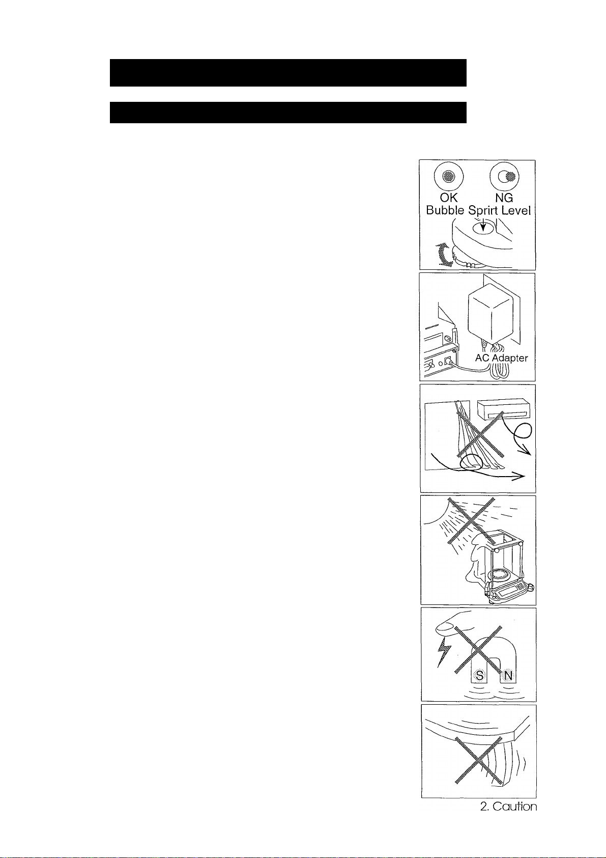
□ Keep the balance level by using the bubble spirit
level.
□ Don’t install the balance near heaters or air
conditioners.
□ Don’t install the balance in direct sunlight.
□ Don’t use the balance near other equipment which
produces magnetic fields.
□ Corners of rooms are best as they are less
prone to vibrations.
□ Calibrate the balance before using and after
moving it to another location.
Do not place or use the balance where there
is flammable or corrosive gas present.
Basic operation
page 5
Page 7
Cautions during use (To get best performance)
Note the following items to get accurate weighing data.
□ Press the | RE-ZERO | key before each weighing to prevent
possible error.
□ Calibrate the balance periodically so as to cancel possible
weighing error.
□ Make each weighing quickly to avoid errors due to changes
in the environmental conditions.
□ Close glass doors to keep out drafts.
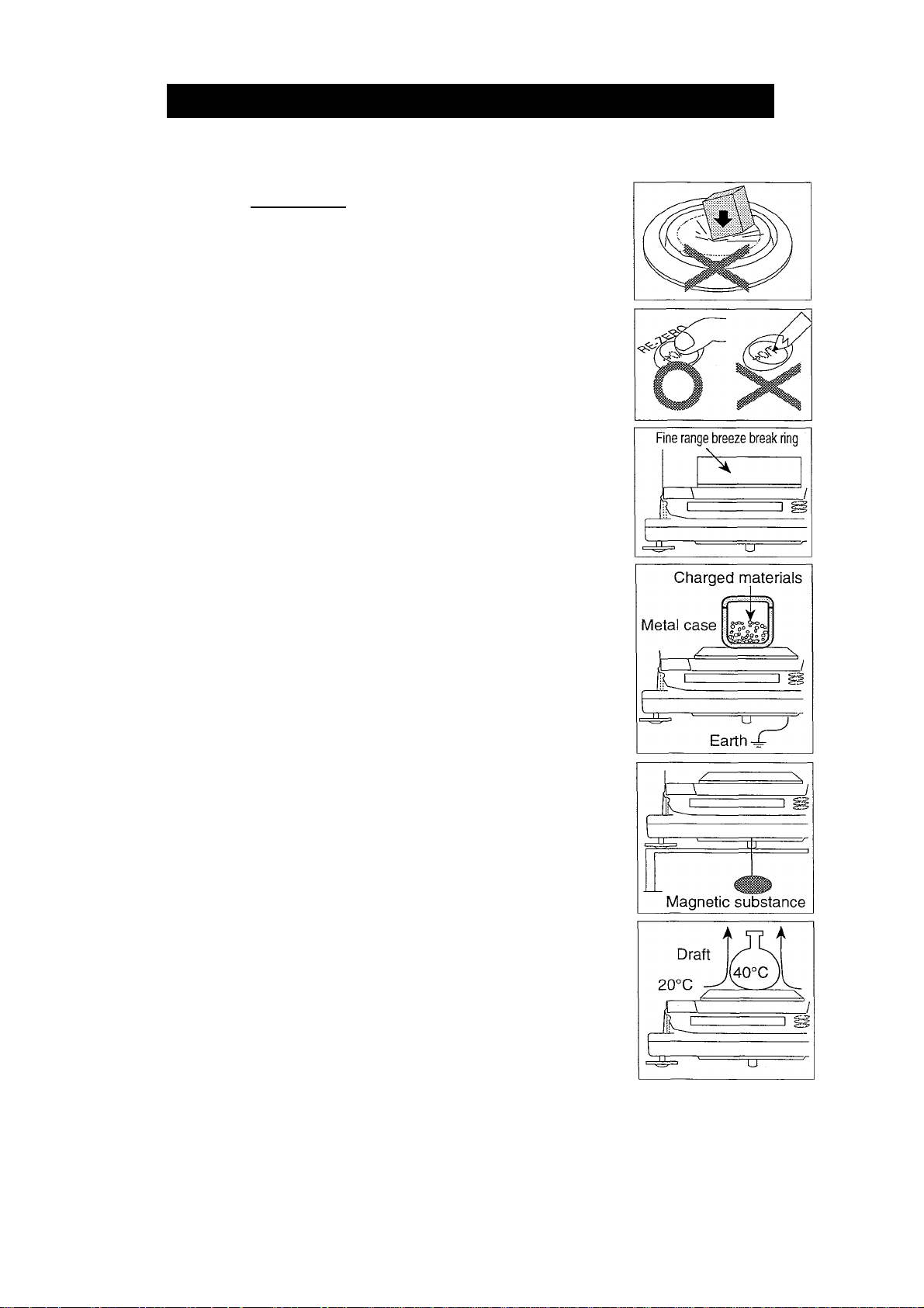
□ Do not drop things upon the weighing pan, or place a
weight beyond the range of the balance on the weighing
pan.
□ Do not use a sharp instmment (such as a pencil or ball point
pen) to press the keys, use your finger only.
□ Toweighproperlywithaminimum display of 0.01 mg using
the GR-202, replace the breeze break ring with the fine
range breeze break ring. See page 8 for details.
□ Dischargestaticelectricityfromtheweighed matter. When
weighing material (plastics, insulator, etc.) could have a
static charge, the weight value is influenced. Try to keep
the ambient humidity above 45%RH or to use the metal
shield case.
□ This balance uses a strong magnet as part of the balance
assembly, so please use caution when weighing magnetic
materials. If there is a problem, use the underhook (on the
bottom of the balance) to suspend the material away from
the influence of the magnet.
□ Cancel the temperature difference between the weighed
material and the environment. When a sample is warmer
(cooler) than the ambient temperature, the sample will
lighter (heavier) than tme weight. This error is due to the
rising (falling) draft next the sample.
□ Take into consideration the affect of air buoyancy on a
sample when more accuracy is required.
2. Caution
Page 6
Basic operation
Page 8
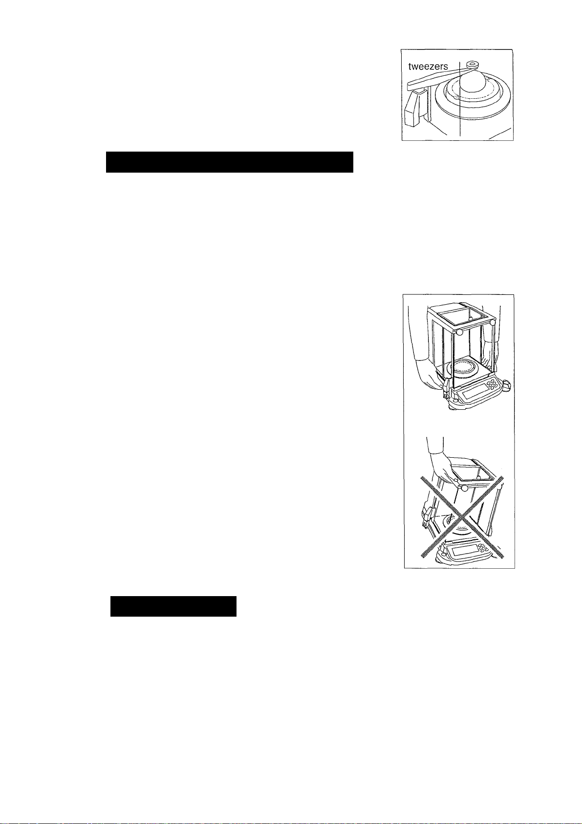
□ Operate your balance gently. Shorten the operation time
as much as possible ( Opening and closing door, placing
and removing material). Use a pairof tweezers (pincette)
to avoid temperature changes due to heat from inserting
your hand into the weighing chamber.
Take Care of Your Balance
□ Don’t disassemble the balance. Contact your local A&D dealer if your
balance needs service or repair.
□ Don’t use solvents to clean the balance. For best cleaning, wipe with a dry lint
free cloth or a lint free cloth that is moistened with warm water and a mild
detergent.
□ When you transport the balance, hold it as shown in
the right illustration. Never lift the balance using the
weighing chamber frame.
□ Keep magnetic substance away from the balance.
□ Avoid mechanical shock to your balance.
□ Avoid dust and water so that the balance weighs
correctly. Protect the internal parts from liquid spills
and excessive dust.
□ Remove and clean the floor plate of the weighing
chamber.
□ Use the special shipping box supplied for transpor
tation.
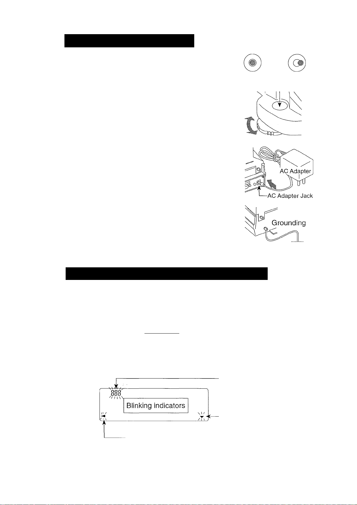
Power Supply
□ When the AC adapter is connected, the balance is in the standby mode if
the standby indicator is on (see "Display Symbols and Key Operation"). This
is a normal state and does not harm the balance. We recommend that you
plug in your balance for at least an hour before use so it can warm up.
Basic operation
page 7
2. Caution
Page 9
3. Unpacking your balance
□
Unpack the balance carefully and keep the packing material if you want to
transport the balance again in the future.
□
In the carton you should find this manual plus :
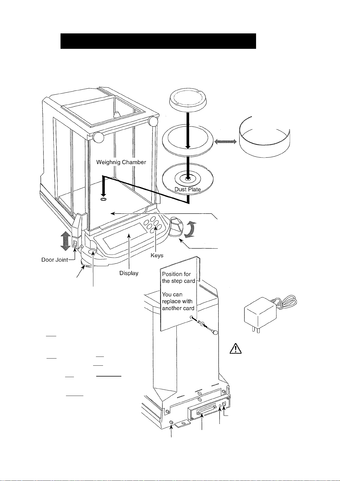
Weighing Pan
Leveling foot
Breeze Break Ring
This “fine range breeze break
ring" is an accessory for the
GR-202. Before weighing on
the fine range, of which the
minimum display is 0.01 mg,
install the this ring in place of
the "breeze break ring" to avoid
errors caused by drafts.
Floor Plate of the
Weighing Chamber
Door Control Lever
A side door can be opened and
closed using the Door Control
Lever, when the Door Joint is
connected to a side door.
Fine Range v
Breeze Break Ring
Bubble Spirit Level
Step Cards
(A step card is attached to the balance)
Response Adjustment
nnnnn I weighing pan, press
t^UQUU» I and hoWIhe O‘ey*"
two seconds.
UUUUUt I weig
Automatic I
The balance adiotnaii
detecting changes in 1
’.^O'uuuua [ ole
bflSfrtC [p'<«''«'VxlKey
dout ~[p'”Slheai«.-Y.
Press the Mod key
Prt
Mi} {i|
Storing Data
PiessrrgiheQ key. the weigrt
value Eslciedmlhe balance.
Keys
if'
Data Memory Function
Setting
^ I Press and he*
two seconds.
__
mtuiiual Q key lor approx,
fECflU [p-gslheQkey
{¿■3SSa
Ihe-*^«-
key to sete cl'f.
Press Ihegkey
and then irre^key
Outputting
___
I Piess and hold It«
two seconds.
Use the loHowng
Piessingthekeylwo
o
o
3. Unpacking your balance
— Grounding Terminal
Page 8
AC Adapter
Please confirm that
the AC adapter type
is correct for your
local voltage and
receptacle type.
-AC Adapter Jack
External Key Jack
'—Serial interface (RS-232C)
Basic operation
Page 10
Installing your Balance
Step 1 Consider the section "2. Caution" for installing
your balance. Place the balance on a firm weigh
ing table.
Step 2 Assemble the "Dust Plate", "Breeze Break Ring"
and "Weighing Pan" on your balance. There is a
reference illustration on the previous page.
Step 3 Adjust the level of the balance using the leveling
feet. Ground the balance chassis for discharging
static electricity if you have a static problem.
Step 4 Please confirm that the adaptertype is correct for
your local voltage and power receptacle type.
Step 5 Connect the AC adapter to the balance. Warm up
the balance for at least one hour with nothing on
the weighing pan.
OK NG
Bubble Sprirt Level
Leveling Foot
Step 6 Calibrate the balance before use.
(Refer to "7. Calibration")
Display Symbols and Key Oiserafion
Processing
indicator
Stabilization
indicator -
Stand-by _
indicator
^ StIS response iF^lMiPnfSLW] r-
>0
Weighing data
or stored data
iDZtpCS t
jniDnig I
•;CtEHfvi
The amount of stored data
with memory data function
Response indicator
Units
Stand-by indicator of
interval memory function
Data number of
displaying data
Basic operation
Active indicator of
interval memory function
A previous notice indicator of automatic self calibration
page 9
3. Unpacking your balance
Page 11
There are two operation types for pressing a key. Each key operation
performs a different function.
First type : "Press and release the key immediately" or "Click the key"
Second type ; "Press and hold the key"
The first type is "to press the key", the first type is normal key operation
during measurement.
Caution
Do not press and hold the key, if you do not perform a rewrite of the internal
parameters.
Press the key
(Press and release the key imediately)
Key Press the key
ON:OFR_
(@)
Display ON / OFF key. The stand-by indicator is displayed, when the
balance is turned off with this key. Weighing data is displayed, when the
balance is turned on with this key.
RANGE-^
Minimum figure of weighing data
is changed.
MODE
____
^
Units are changed (selected
from the function table). Refer
to section "4. Weighing Units".
CAL ^
This key performs calibration of
the balance using the internal
(S>
weight.
Press and hold the key
Press and hold the key
The function table menu is displayed.
Refer to section "9. Function table"
Response adjustment is performed.
Other items of the calibration menu
are displayed.
Weighing data is stored in the
balance (Factory setting) or is
output to the RS-232C inter
face. This key functions
Data memory menu or GLP menu is
displayed. This key functions accord
ing to the function table. Factory setting
is "not used".
according to the function table.
RE-ZEBOL The key sets the display to zero. This key returns a weighing value to the
center of zero when the weighing pan is empty, and can also tare (cancel)
the weight of container and/or sample. Please use this key before each
weighing to cancel possible error.
3. Unpacking your balance
Page 10
Basic operation
Page 12
4. Weighing
The most common unit of weight used around the world is grams, but there
is often a need to shift to an alternative unit specific to the country where
the balance is used or to select modes such as counting or percent.
The unit can be select by the function table. The units are as follows (if some
are missing please refer to your dealer):
[üjQ
Note
Percent mode
Counting mode
Milii-qram
Gram
(Density mode)
m
Messgha[/^
Tola(lndia)
If a mode (or unit) of weight has been turned off, the sequence will be missing
that mode or unit. There are also the various Tael that can be included if
necessary. (Tael is selected as a unit from four units installed at the factory)
If the law in your area permits, you may use all of the units, or at this
software level you can disable the weighing units you don’t regularly
use. Also, some dealers may initially turn OFF units which are not
regularly used, but you may want to turn them back on.
pcs
Tael
Ounce (Avoir)
d*t^
^ ^Pennyweight
\ Grain
Troy Ounce
Hj Metric Carat
a
mnni- Mflmme
Conversion table
Abb rev.
mg
oz Ounce (Avoir)
ozt Troy Ounce
ct Metric Carat
mom
dwt
GN
TL
TL
TL
TL
t
mes
Basic operation
Name Conversion
Milli-gram 0.001 g
28.349523125 g
31.1034768 g
0.2 g
momme
Pennyweight 1.55517384 g
Grain (UK)
Tael (HK general. Sing.) 37.7994 g
Tael (HK, jewelry)
Tael (Taiwan)
Tael (China)
Tola (India)
Messghal
3.75 g
0.06479891 g
37.429 g
37.5 g
31.25g
11.6638038 g
4.6875 g
page 11
4, Weighing Units
Page 13

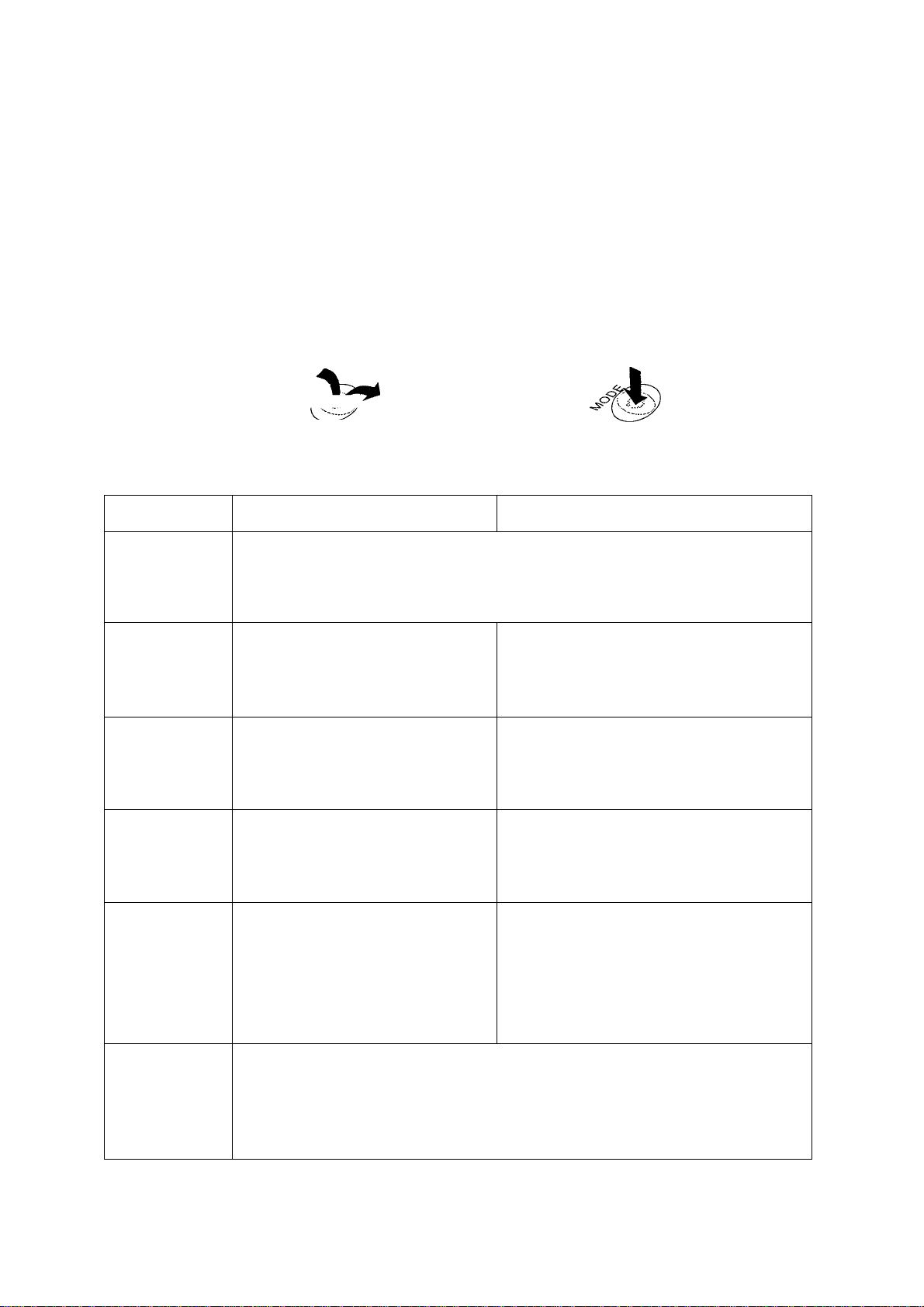
Operation of unit selection
The unit can be selected in the function table. The sequence of displaying
the unit can be arranged so as to fit the frequency of use in the function
table. According to the sequence of displaying unit, the units can be
changed with the [MODE key at the weighing mode.
Selecting a unit and arranging the sequence of display
Step 1 Press and hold the RANGE key to display
/ iirr-
Lf ‘ I J I n L
of the function table.
Step 2 Press the [RANGE key several times to display \Un it
Step 3 Press the [PRINT key to enter into unit selection.
Step 4 The unit can be selected using the following keys.
The unit display sequence is in the order of pressing the | RE-ZERO key.
MODE I key The key to sequentially display the units.
RE-ZERO I key The key to select a unit. The jO | indicator is
displayed at unit selected.
Step 5 Press the PRINT key to store the units. Then the balance displays next
menu id of the function table.
Step 6 Press the |CAL| key to exit the function table. Then the balance returns
to the weighing mode.
4. Weighing Units
Page 12
Basic operation
Page 14

5. Wéighing
Cautions for the weighing operation
□ Operate your balance gently.
□ Press the RE-ZERO key to prevent possible error before placing material
on the pan (weighing material) each time.
□ Shorten the operation time as much as possible. ( Opening and closing
door, placing and removing material)
□ Temperature changes during measurement may cause weighing error.
□ Use a pair of tweezers (pincette) to avoid a temperature change that Is due
to having your hand in the weighing chamber.
□ Calibrate your balance periodically to maintain weighing accuracy. Refer
to section "T.Calibration".
□ Electrified material or magnetic body may cause a weighing error.
□ Do not press keys with a sharp instrument (such as a pencil or ball
point pen).
□ Do not drop things on the pan, or place a weight on the pan that is
beyond the weighing range of the balance.
□ Keep the area clean and dry.
□ Consider section "2. Caution" for weighing operation.
Basic Operation (gram mode)
Step 1 Calibrate your balance before use. (Refer to section "7. Calibration")
Step 2 Place a container on the weighing pan, if necessary.
Press the | RE-ZERO | key to cancel net weight. The balance displays zero.
Container: A vessel placed on the pan, but not to be included in the
weighing data.
Step 3 Place material on the pan or in the container.
Step 4 Wait for the stabilization indicator to be disipayed and read the value.
Step 5 Remove the material and container from the pan.
Basic operation
page 13
5. Weighing
Page 15

Counting Mode (pcs)
Selecting the counting mode
Step 1 Select the unit [p^ using the [MODE key. If the counting mode can not
be selected, refer to section "4. Weighing Units". ([p^ : pieces)
Storing a unit weight
Step 2 Press the [RANGE key to enter the sampling mode.
Step 3 If you want to select the number of items to be used for the sample, press
the [range I key (several times). It may be set to 10, 25, 50 or 100.
Step 4 Place acontaineron the weighing pan, if necessary. Pressi RE-ZERO [key
to cancel this weight,
ex.
I il [1 pcs[ is displayed in the case of 10 items.
Step 5 Place items on the pan. This number of items is the same quantity as
the number displayed (10, 25, 50 or 100).
Step 6 Wait for the stabilization indicator to come on. Press the [PRINT key to
calculate the unit weight and store it.
Counting Items
Step 7 You are now able to count the items by placing them on the pan.
Counting mode using the ACAI function
ACAI™ (Automatic Counting Accuracy Improvement) is a function that
improves the accuracy of the unit weight.
Step 8 If you add a few more items, the ACAI indicator turns on.
(The ACAI indicator turns off if in overload)
Step 9 The balance re-calculates the unit weight while the ACAI
indicator is blinking. Wait and do not touch the items on
the pan until the ACAI indicator turns off automatically.
Step 10 You are now able to count items with a more accurate unit
weight.
Stepll If you add a few more items, proceed to step 8. The
balance re-calculates a more accurate unit weight.
ACAI indicator
i
Detectinq items
, 1,
◄
Calculating
unit weight
7
Counting mode
pcs
pcs
pcs
5. Weighing
Page 14
Basic operation
Page 16

Percent Mode (%)
Selecting the unit of percent nnode
Step 1 Select the unit % using the MODE key. If the percent mode can not be
selected, refer to section "4. Weighing Units". ( % : percent)
Storing 100% weight
Step 2 Press the | RANGE key to enter the sampling mode.
Step 3 Place a container on the weighing pan, if necessary.
Press the | RE-ZERO | key to cancel the container weight and possible
error. The balance displays I//7/7 B%
Step 4 Place the item of 100% weight on the pan or in the container.
Step 5 Press the [PRINT key to store this 100% weight.
Step 6 Remove the item from the pan.
Reading percentage
Step 7 You are now able to read the percentage based on the stored 100%
weight.
Basic operation
page 15
5. Weighing
Page 17
6. Response Adjustfinent
This function stabilizes the weight value, reducing the influence on weigh
ing that is caused by drafts and/or vibration at the place where the balance
is installed. This function adjusts by automatically analyzing the environ
ment or by hand-operation. The function has three stages as follows :
Indicator Function table Summaries
FAST
MID.
SLOW
RESPONSEÎrASTIIMlD.lfSlLÜWl'
fin 11 11 ft
yyijyij
Note
□ If the automatic response adjustment is to awkward, Try to refine it using
the section "Manual Response Adjustment".
^ - J
L Ü n U U
r _ 1 1
L U > 1 LI t
r . ^ J Zl
L Û n U L
Response Indicator
Fast response. Sensitive value
Slow response. Stable value
□ The response adjustment can be changed at "Condition {[and)" of
"Environment & Display {bnSi-nc)" in the function table. Refer to "9.
Function table".
Automatic Response Adjustment
This way automatically updates the response adjustment by analyzing the
influence of the environment on the weight data.
Operation
Step 1 Press and hold the [MODE | key until [RESPONSE
displayed.
Step 2 The balance analyzes the influence and updates the
response adjustment. If you want to cancel this
update, press the |CAL| key.
is Press and hold the key.
RESPONSE
- Release the key.
RESPONSE
r U
L ) I ... ,,, ...
Caution
Do not allow vibration or drafts to affect the balance.
Step 3 The balance returns to the weighing mode automati
cally and displays the updated response indicator.
6. Response Adjustment
Page 16
\}
RESPONSE tvî5~l
$ u 1)} $ $ i W
y.uuuu s
Adapting to environment
Page 18

Manual Response Adjustment
This way updates the response adjustment manually.
Operation
Step 1 Press and hold the |MODE key until |RESPONSE! is displayed
Press the jMQDE key immediately.
Step 2 Select a stage of the response adjustment using the |MODE key. Either
FAST or MID. or SLOW can be selected.
Step 3 The balance automatically returns to the weighing mode after a few
seconds of inactivity.
Adapting to environment
page 17
6. Response Adjustment
Page 19

7. Calibration
Calibration Group
The GR series has the following modes concerning calibration and calibra
tion test.
□
Automatic Self Calibration
□
Calibration using the internal weight
Calibration using an external weight
□
Calibration test using the internal weight
□
Calibration test using an external weight
□
Correction of the internal weight value
□
Note
□ Calibration is controlled by the parameters of "Permission or prohibition".
Refer to section "8. Function Switch and Initialization".
□ The weight which can be used for calibration is called "the calibration
weight". The weight which can be used for calibration test is called "the
target weight". The weight which you have is called "the external weight".
Caution
□ This calibration achieves the adjustment for accurate weighing. It is
necessary to perform calibration in the following case.
• When the balance is installed for the first time.
• When the balance has been moved.
• When the ambient environment has changed.
• For periodical calibration.
□
Prevent vibration, drafts, and ambient temperature changes from the
influence for the balance during calibration.
□
□
The data for CLP (Good Laboratory Practice) can be output using the RS232C interface, when the "CLP output (,F q )" of "Data output {do u b)" is
set to " /" orRefer to section "9. Function table".
This indicator means "the balance is measuring calibra
tion data". Do not allow vibration or drafts to affect the
balance while this indicator is displayed.
Caution using an External Weight
□ The accuracy of an external weight can influence the accuracy of weighing.
Product
GR-120
GR-200
GR-300
GR-202
7. Calibration
Usable external weight
lOOg, 50g
200g,lOOg
200g, 300g
200g, 100g
Page 18
Adjustable range
+15.9 mg ~ -15.0 mg
Adapting to environment
Page 20

Automatic Self Calibration
This function automatically calibrates the balance, when the balance
detects an ambient temperature change.
When the balance detects a change in ambient tem
perature, this indicator blinks and automatic self calibra
tion is required. If the balance is not used for several
minutes with this indicator blinking, the balance pre
forms automatic self calibration. The environment will
affect the time that the indicator blinks.
r i;ii
I. III.
This display means "the balance is measuring calibra
tion data". Do not allow vibration or drafts to affect the
balance while this indicator is displayed.
Advice
You can use the balance while the indicator blinks. But, it is recommended
that to maintain the best accuracy, stop using the balance and confirm that
there is nothing on the pan when the indicator starts blinking.
Caution
□ Do not place anything on the weighing pan during automatic calibration.
Control of Automatic Self Calibration
Automatic self calibration is controlled by a parameter in "Permission or
prohibition". Refer to section "8. Function Switch and Initialization"
n n
II IJ
i 1 i
i 1 ?
Adapting to environment
-Automatic Self Calibration
0 : Not used
1 : Used
page 19
7. Calibration
Page 21

Calibration Using the Internal Weight
This function calibrates the balance using the internal weight.
Operation
Step 1 Connect the AC adapter and warm up the balance for
at least one hour with nothing on the weighing pan.
Step 2 Press the CAL| key to start calibration.
Step 3 The balance displays\[nj ~ m\ and performs calibra
tion. Prevent vibration and drafts from affecting the
balance.
Step 4 Ifthe "CLP output ( ,n/-o)" of the "Function Table" isset
to
232C interface.
Step 5 The balance will automatically return to the weighing
mode after calibration.
or "P", "Calibration Report" is output from RS-
Step 6 Test the accuracy of weighing using the calibration test
function or by using a certified test weight.
Control of this Calibration
Calibration using the internal weight is controlled by a
parameter in "Permission or prohibition". Refer to section
"8, Function Switch and Initialization".
n n M ( i
II U M M
-----------A--
-Calibration Using the internal Mass
0 ; Not used
1 : Used
7, Calibration
Page 20
Adapting to environment
Page 22

This function tests the balance accuracy using the internal weight.
Operation
Step 1 Connect the AC adapter and warm up the balance
for at least one hour with nothing on the pan.
o nnnnri
ULIUUU 9
Step 2 Press and hold the CAL key until display-
ing
I I
L L in
and then release the key.
Step 3 The balance measures the zero point.
Prevent vibration and drafts to affect the balance.
Step 4 The measured zero point data is displayed.
Step 5 Ready for the internal weight measurement.
Step 6 The balance measures the internal weight.
Prevent vibration and drafts to affect the balance.
Step 7 The internal weight data is displayed.
Step 8 The balance informs you when the calibration test
is finished. If the "CLP output ( ,n/-o)" of fh®
"Function Table" is set to " /" or "P", "Calibration
Test Report" is output by the RS-232C interface.
Press and hold the key/C
f ra
-Release the key
______
innnrmn
C UUJJLIUU 9
GLP output
CalibrationTest Report^
r r
t L
r r
1- .
^
nnnnn
UUUUU 9
r r
L L
J
I OU
in g
)■
Step 9 Thebalancewill automatically return to the weigh
ing mode after the calibration test is finished.
Adapting to environment
page 21
O nnnnn
UUUUU 9
7, Calibration
Page 23
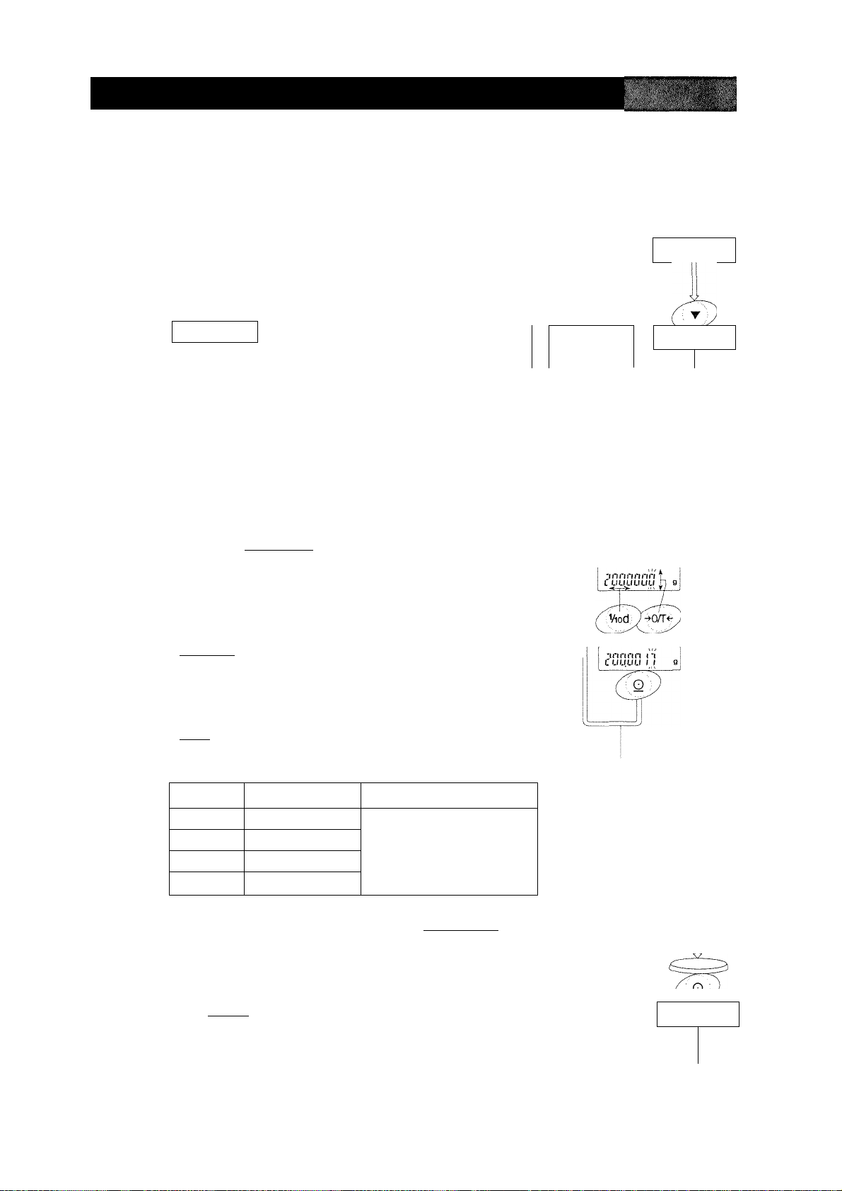
4^ Calibration Using an External Weight
This function calibrates the balance using an external weight. The weight
to be used for calibration is called "the calibration weight". The weight which
you have is called "the external weight".
Operation
Step 1 Connectthe AC adapter and warm up the balance
for at least one hour with nothing on the pan.
o
nnrinn
u.uuuu g
Step 2 Press and hold the CAL key until displaying
r n 1
L ‘ 1 L Û U L
Step 3 The balance displays
and then release the key.
r n I
L ' I L
□ If you want to change the calibration weight
value, proceed to step 4.
□ If you use the stored calibration weight value
in the balance, proceed to step 5.
Step 4 Press the ¡RANGE | key and adjust the calibration
weight value using the following keys.
RE-ZERO
key
The key to set the value of the
digit selected.
RANGEi key
The key to select the digitto change
value.
PRINT key
The key to store a new weight
value and return to step 3.
CAL key
The key to cancel this change
and return to step 3.
Product Usable weight
GR-120
GR-200
GR-300
GR-202
lOOg, 50g
200g, 100g -f15.9 mg ~ -15.0 mg
200g, 300g
200g, 100g
Adjustable range
Press and hold the key
1 ro. . ' <70
(J
■Release the key
=zzz=z=zz:>
ex. calibration weight
value = 200.0017g
Initial calibration
weight value is
200.0000g at
GR-200.
[ fit Out
r 01 n
L riL LI
Note Digits cyclically change using the ¡RE-ZERO key.
ex. 0mg-^-h15mg-^-15mg-^0mg
Step 5 Confirm that there is nothing on the pan and press
the jPRÎÏ^ key. The balance measures the zeropoint. Prevent vibration and drafts from affecting
the balance.
7. Calibration
Page 22
r o> n
LUL U
To Next Page)
}
Adapting to environment
Page 24

Step 6 Place the displayed calibration weight on the pan
and press the PRINT key. The balance displays
the measured calibration weight. Prevent vibra
tion and drafts from affecting the balance.
Step 7 Remove the weight from the pan after the balance
displays |£nd !■
Step 8 If the "GLP output ( ,n/-o)" of the "Function Table
" is set to " /" or "P", "Calibration Test Report" is
output by the RS-232C interface.
À
....................
f i
GLP output
Calibration report
:
[~ncl
'rnn
1 u u
Step 9 The balance will automatically return to the weigh
ing mode after calibration.
StepIO Test the accuracy of weighing using the calibra
tion test function with a certified test weight.
Control of this Calibration
Calibration using an external weight is controlled by
a parameter in "Permission or prohibition". Refer to
section "8. Function Switch and Initialization"
n n Î I i !
n ' U I I ! !
-Calibration Using the External Mass
u : Not used
I : Used
nnnnn
U.ULIUU
Adapting to environnnent
page 23
7, Calibration
Page 25

Calibration Test
This function tests the balance for the accuracy using an external weight.
A weight which is used for the calibration test is called "the target weight".
The weight which you have is called "the external weight".
Operation
Step 1 Connect the AC adapter and warm up the balance
for at least one hour with nothing on the pan.
Step 2 Press and hold the CAL key until displaying
LI U L
Step 3 The balance displays
and then release the key.
n
u
□ If you want to change the target weight value,
proceed to step 4.
□ If you use the stored target weight value in the
balance, proceed to step 5.
Step 4 Press the j RANGE key and adjust the calibration
weight value using the following keys.
RE-ZERO [ key
The key to set the value of the
digit selected.
RANGE key
Thekeytoselectthedigittochange
value.
PRINT key
The key to store a new weight
value and return to step 3.
CAL]key
The key to cancel this change
and return to step 3.
Product Usable weight Adjustable range
GR-120 100g, 50g
GR-200 200g, 100g -1-15.9 mg ~ -15.0 mg
GR-300 200g, 300g
GR-202
200g, 100g
Press and hold the key
ciuc
-Release the key
,Viod
ex. target weight
value = 200.0017g
Initial target weight
value is 200.0000g
at GR-200.
Note Digits cyclically change using the , RE-ZERO | key.
ex. 0mg^-h15mg-^-15mg-^0mg
Step 5 Confirm that there is nothing on the pan and press
the PRINT key. The balance measures the zero-
point and displays it. Prevent vibration and drafts
from affecting the balance.
7. Calibration
Page 24
r r n
L L LI
o
rinnnn
u.uuuu
(To Next Page)
Adapting to environnnent
g
Page 26

step 6 Place the displayed target weight on the pan and
press the PRINT | key. The balance displays the
measured target weight and displays it. Prevent
vibration and drafts from affecting the balance.
Step 7 Remove the weight from the pan after the balance
displays
L 11 U
Step 8 If the "GLP output ( ,n/-o)" of the "Function Table
" is set to " /" or "P", "Calibration Test Report" is
output by the RS-232C interface.
Step 9 The balance will automatically return to the weigh
ing mode after calibration.
innrtri 11
LUU.UU } i
cno
GLP output
Calibration test report
"end
r 1
nnnnn
UJJLiUU 9
9
Adapting to environment
page 25
7, Calibration
Page 27

[JC
Correcting the Internal Weight Value
The GR series can correct the internal weight value within +1.5 mg. The
initial internal weight value of the GR-120 is 100.0000 g. The initial internal
weight value of the GR-200, GR-300 and GR-202 is 200.0000 g.
Weighing the same weight
The internal weight is corrected to
+0.6 mg. The balance is calibrated
with the internal weight.
Operation
Step 1 Turn off the display using the ^ON:OFF key.
vr'.'ii - ;' ■
___________
Step 2 Press the[orrOFF I key while thePrange [key
and [ PRINT I key are pressed and held. Then
the balance displays
n r
r I
Step 3 Press the PRINT key. Then the balance displays
the switches.
Step 4 Set the following switches to " /".
|RETERO| key The key to select the setting of
the switch.
~RANGe1 key The key to select the switch to
change the setting.
0 . I y y y I
II (XXX/-
Switch for the function table
Switch for the internal weight
Step 5 Press the PRINT key to store the new setting.
The balance will return to the weighing mode.
While press q
hold these keys^
+
Press the key
n n I I I I
II U I f I I
0. f ,
If I ^
o
nnnnn
LI LIU LIU
■ I f
9
Step 6 Press and hold the , RANGE key to enter the
function table and release the key when
is displayed.
Step 7 Press the [RANGE key several times to display
; I
L 3 I II
7, Calibration
Page 26
L O L “
U ‘ I J > > I c
Adapting to environnnent
Press and
hold the keyP
(JhNexTPage)
LOCC^.
CinjI Hi
r r
L J III
Page 28

Step 8 Press the | PRINT
for correcting the internal weight value.
Step 9 Correct the internal weight value using the follow
ing keys.
RE-ZERO, key The value is selected.
PRINT^i key The new value is stored and
CAL key This correction is canceled and
Step 9 Press the CAL key. The balance will return to the
weighing mode.
Step 9 Press the |CAL | key to calibrate the balance.
1
key to enter into the procedure
(-1-1.5 mg ~ -1.5 mg)
is displayed.
is displayed.
Control of the Correction
Correction of the internal weight value is controlled
by the parameters in "Permission or prohibition".
Refer to section "8. Function Switch and Initializa
tion"
ri (Mil
n lint
-Function table
u : Change not permitted
-Correction of the internal weight
u : Not used
i : Change permitted
I : Used
Adapting to environment
page 27
7, Calibration
Page 29

8. Function Switch and initiaiization
—'-r'
Permission or Prohibitio
The balance stores parameters that must not be changed carelessly (ex.
Calibration data for precision weighing, Data for adapting to environment,
Control data for RS-232C interface, etc.). There are five switches for the
purpose of preserving these parameters. Each switch can select either
"permission" or "prohibition". The "prohibition" protects careless operation.
Switches
n n I I I I
II LI I I I I
(Factory setting)
Function Table
[I : To inhibit change to the function table.
/ : To permit change to the function table.
Calibration with the Internal Weight
0 ; To inhibit calibration.
I : To use calibration.
Calibration with an External Weight
0 : To inhibit calibration.
/ : To use calibration.
Automatic Self Calibration
[! : Not used
/ : Used
Correcting the Internal Weight
0 : To inhibit correction.
/ : To use correction.
Operation
Step 1 Turn off the display using the ON:OFF| key
Step 2 Press the ON:OFF key while the
pressed and held. Then the balance displays PS
Step 3 Press the PRINT key. Then the balance displays the switch settings.
Step 4 Set the switches using the following keys.
RE-ZERO I key The key to change the setting of the switch.
RANGE key The key to select the switch to change the setting.
print] key The key to store the new setting.
CAl] key The key to cancel this operation.
8, Function Switch and Initialization Page 28
RANGE key and PRINT key are
Adapting to environment
Page 30

in p |.y^i
Initializing the Bal
This function returns the following parameters to factory settings.
□ Calibration data.
□ Function table.
□ The 100% weight
□ The data that is stored in the balance using data memory function.
□ External calibration weight and target weight.
□ Switch settings for "Permission or prohibition".
Operation
Step 1 Turn off the display.
" ■№ Nl*>
Step 2 Press the [q]^FF I key while the [range ¡key While press
and PRINT I key are pressed and held. Then
hold these keyd^
the balance displays \PS
Press the key(
Step 3 Press the [RANGE key to display f /. r
Step 4 Press the PRINT key. (If you want to cancel this
operation, press the CAi^ key)
Step 5 Press the , RE-ZERO | key
Step 6 Press the PRINT key to initialize the balance.
The balance will automatically return to weighing
mode.
o
I L r no
rt . r ^
LL I UQ
r I
UlO
o nnnnri
LtULIUU
Adapting to environment
page 29 8. Function Switch and Initialization
Page 31

9. Function Table
The operation of the "Function Table" is to read or rewrite the parameters
that are stored in the balance. These parameters are stored until the next
change even without power applied.
Caution
The balance may not work effectively when a combination of param
eters and environment are not proper. Confirm the parameter before
changing it.
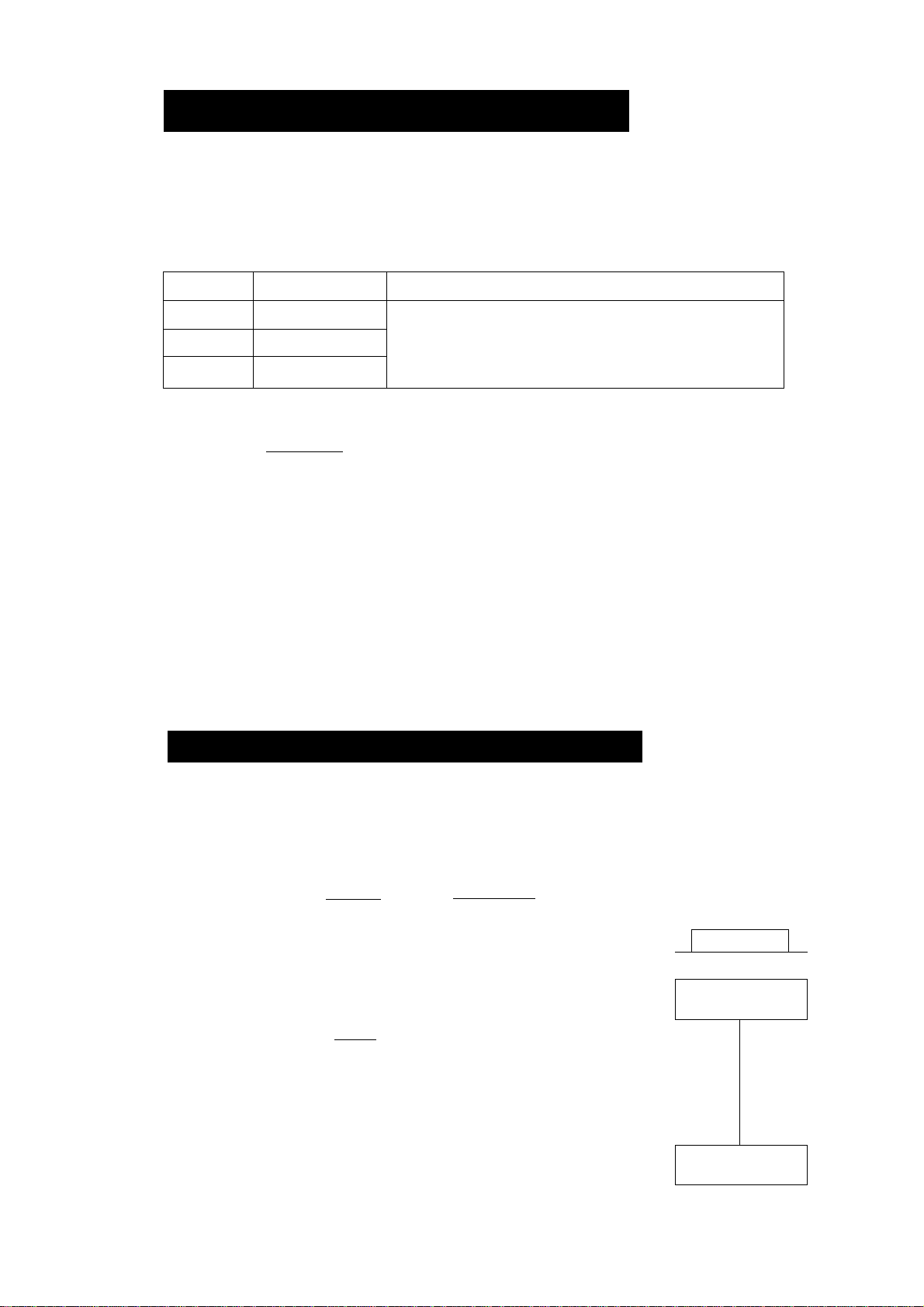
Structure and Sequence of the Function Table
The function table menu consists of two layers. The first layer is the "Class"
and second layer is the "Item". Each Item stores a parameter. The effective
parameter is the last parameter that is displayed in the sequence. New
parameters operate upon the balance after pressing the ¡PRINT key
Example
This example sets "use" to "Data memory" and "every minute" to "Inten/al time".
....■; —
.„■■ —*. ............... .. ........^ -
............................................
■
Start, From weighing mode
End, To weighing mode
Control of this Function Table
The function table is controlled by a parameter in "Permission or prohibi
tion". Refer to section "8. Function Switch and initialization"
Press some keys several times.
tern
"Data memory"
Parameter
"Use"
ih
Parameter
Every minute"
n M M I
II I M M
9, Function Table
-Function table
u : Change not permitted
I : Change permitted
Page 30
Functions
Page 32

Display and Keys of the Function Table
The "o" symbol is displayed at a selected parameter.
When the key is pressed and held in weighing mode, the
balance enters the "function table mode".
The key to change the class or item in the function table
mode.
The key to select the parameter, when the balance
displays an item.
PRIN
CAL
The key to move to an item from the class, when the
balance displays a class.
The key to store new parameters and display the next
class, when the balance displays an item.
The key to cancel new parameters and display the next
class, when the balance displays an item.
The key to exit the function table mode, when the
balance displays a class.
Functions
page 31
9, Function Table
Page 33

Details of the Function Table
Class
1 П Г г
О 1 1 _l 1 1 1 L
Environment,
Display
1 1
LI U LI L
Data output
Item
r /
L U ‘ 1 LI
Condition
j t ~ b
stability band width
1
L ‘ L
Zero tracking
r n 1
J 1 LI
Display update rate
n _ f_
1 1 1 L
Decimal point
n
1 u 1 1
Automatic start
ri 1
1 1 /_
Data output mode
Param
eter
Г/
LI
1
• 1
~l
П
и
• 1
“/
l_
П
LI
1
• 1
ri
• LI
1
1
П
* LI
1
1
П
• U
1
1
П
• LI
1
1
~l
L
Summaries
Fast response, Sensitive value ; Common data of "Response
i adjustment".
Slow response and stable value i
Stable when within ±1 digit j The stability indicator lights when
\ the display fluctuation is within
Stable when within ±3 digit the range per second.
OFF ; The function to keep zero display
ON ;by tracking zero-drift.
Normal, 5 times/second ; The period to refresh the display.
Fast, 10 times/second
Point (.) ; The form of decimal point.
Comma (,)
OFF ; Connecting adaptor, the display
ON i turns on without key operation.
Key mode ; Data is output or stored with
i PRINT key and stability indicator.
Auto-print mode A ; Data is output or stored when the
(Standard value is zero) j display value is stable and meets
Auto-print mode В : the conditions of p,p - p, pp-p
(Standard value is last and standard value,
stable value)
n n n
n r 1
Auto-print polarity
for mode A or B
n n 1
III LI
Auto-print difference
for mode A or B
1 n L n
0 i~l L 1 1
Data memory function
1 l~l t
Interval time for
Data memory function
n
Stream mode / Data is output continuously.
J
Inteval memory mode ; In case of ,jPt P !,
Data memory function is used.
In case of o'/i't-T [1,
n
• LI
Plus polarity : Display value > Standard value
1
Minus polarity i Standard value > Display value
1
“/
Both polarities (Absolute value) i Display value > Standard value о
Г
: Standard value > Display value
• }
• LI
• LI
П
LI
1
■/
i_
П
1
П
1
1
n
Г
n
J
Ч
г
_l
г
и
~l
1
n
0
10 digit i Difference between standard
100 digit : value and display value
1000 digit
Not used ; Relation 1, mt.o'-no
Use
Every Measurement
Every 2 seconds , Interval time is selected on
Every 5 seconds ^Prt j,dPtn /■
Every 10 seconds
Every 30 seconds
Every 1 minute
Every 2 minutes
Every 5 minutes
Every 10 minutes
9. Function Table
; factory setting. *; "Digit" is the unit ot minimum display.
Page 32 Functions
Page 34

Class Item
/ $
Q U U L
Data output
r r
J 1
Serial Interface
/ r r
O 1 n c
Specific gravity
measuring mode
/
U ~ > 1 LI
Data number output
n 1 1 r r
• U -.1 L
Data pause
n t r
1 1 L '
Auto feed
1 n r u
GLP output
n 1
'll o
Zero after output
1 n r
U ' 3
baud rate
f 1 n
LI L ' ‘
Length, Parity bit
L L
Terminator
1 tin r
L ' C
Data format
t_ 1 1 n
L LI 1
Receive time
r r 1
L ' L LI
<AK> and error code
L L 3
CTS control
1 1
L U 1 ' 1
Liquid density
Param
eter
n
• u
1
1
n
• LI
1
1
n
• LI
1
1
n
• U
1
1
~l
L
n
• LI
1
1
n
LI
1
1
~l
• L
~l
_l
1 1
1
n
• LI
1
1
~l
L
n
• LI
1
i
n
• LI
1
1
“/
L
~l
_l
1 1
1
n
LI
1
* /
n
• LI
1
1
n
• LI
1
1
• n
LI
/
1
Summaries
No output Refer to section "11, Data memOutput ; ory function".
No pause ; Selection of output interval.
Pause (1,5 second)
Not used ; Selection of paper feed after
Use i printing.
No output
AD-8121 format ; The type of GLP data output
Data format
Not used
Use
600 bps
1200 bps
2400 bps
4800 bps
9600 bps
7 bits, even parity check
7 bits, odd parity check
8 bits, no parity check
CR LF iCR : ASCII code ODh
CR ; LF; ASCII code OAh
A&D standard format
DP format ; Refer to section "Explanation
KF format ; of data format"
MT format
NU format
No limit i Waiting time during a command.
For one second
No output ; AK ; ASCII code 06h
Output
Not used
Using CTS and RTS ; Keep the RTS line (active) high
; while the computer receives data
i CTS low will be set if if is busy.
Enter the water temperature, i Available only when the spcitic graEnter the density directiv ^ fTieasuring mode is selected,
tnter me aensity aireciiy. , "i3.Specific gravi-
I ty (density) measurement".
u n /1
Unit
Lb in
Correction of internal weight
/
1 u
ID number
Caution
When the baud rate is set to 2400bps or less, the output rate is slower
than the display update rate and the balance may not transmit the data
completely (and transmits it intermittently).
Functions
Refer to section "4.Weighing Units"
Refer to section "7.Calibration"
Refer to section "10.ID number and GLP"
• : factory setting.
page 33
9. Function Table
Page 35

Explanation of Item "Environment, DispI
Condition { L ond )
“ - ^ J I I
L U I I U U
L U ‘ I LI L
This parameter is for sensitive response to the fluctuation of
a weight value. Use for target weighing of powder, weighing
of a very light sample or weighing requiring quick response.
This parameter is for stable weighing with slow response. Use
to prevent a weight value from drifting depended on the
balance location.
Stability band width ( St - b )
This item controls the width to regard a weight value as a stable value.
When the fluctuation per second is less than this parameter, the balance
displays the stability indicator and outputs or stores the data. This param
eter influences the "Auto-print mode"
n
This parameter is for sensitive response of the stability
LI
indicator. Use for exact weighing.
p This parameter ignores slight fluctuation of a weight value.
Use to prevent the weight value from drifting.
Zero tracking ( t <- c )
This function traces zero point drift and keeps a zero display automatically,
when the weighing value drifts due to changes in the environment.
t r r 0 The tracking function is not being used. Use for weighing of
J a very light sample.
hrr I The tracking function is used.
Display update rate ( SPo' )
The display update rate influences "Baud rate", "Data pause" and "Stream
mode".
Decimal point ( t't )
The decimal point form can be selected.
Automatic start ( p
When the AC adapter is connected, weighing is automatically started
without key operation. Use for a built-in balance in a system. Warm-up for
at least one hour is necessary for accurate weighing.
o n
)
9. Function Table
Page 34
Functions
Page 36

'LH
lanation of Item "Data output mode
The SPRINT key can be used at any time for transmitting data.
Key Mode
When you press the ¡PRINT j key and the display value is stable, the balance
outputs the weighing data and the display blinks one time.
Required setting dout Prt 0 Print key mode
Auto-Print Mode A
When the display value is stable and meets the conditions of "Auto-print
polarity", "Auto-print band" and standard value (of zero point), the balance
outputs the weighing data. If you press the [PRINT key, the balance outputs
the data and the display blinks one time.
w
Required setting
Example
Auto-Print Mode B
When the display value is stable and meets the conditions of "Auto-print
polarity", "Auto-print band" and standard value (of last stable value), the
balance outputs the weighing data. If you press the| PRINT ¡key, the balance
outputs the data and the display blinks one time.
Required setting daub Prt c Auto-print mode B
Example "Transmitting the data of each operation."
Stream Mode
The balance outputs the weighing data continuously.
Required setting dout Prt 3 Stream mode
U LI LI L
J - L
LI LI LI L
_ L
n n n
nr " r
Auto-print mode A
Auto-print polarity
u u LI c nP - b Auto-print band
"Weighing and removing one item."
dout PiP-P Auto-print polarity
do LI t nP - b Auto-print band
U LI LI L
I I
LI O LI L
I n r r
LI I I J ' I I L
J 11
I ri I n n
LI I I L I I LI
r n I
J I Cl
L O ~
LI I J
Data memory function is not used.
Display update rate
Baud rate
Caution
Functions
Example
"Monitoring data on a computer"
When the baud rate is set to 2400bps or less, the display update rate
is faster than the output rate and the balance may not transmit the
data completely (and transmits it intermittently).
page 35
9. Function Table
Page 37

Interval Memory Mode
This is the data memory function mode. Weighing data is periodically
stored in the balance. The interval memory mode can not be used, while
stream mode is used.
Required setting
Example
LI LI LI L
"Periodical weighing without computercommand and output
n _ L
I I I
I n I n
Q n L ‘ t
Stream mode
Data memory function is used.
Interval time
ting all of the data to a computer at one time"
Explanation of Item "Data format"
A&D standard format f, ,/-
This format is used when the peripheral equipment is capable of receiving
A&D format. If an AD-8121 is used, set the printer to mode 1 or 2.
□ This format consists of fifteen characters (excluding the terminator).
□ A header of two characters indicates the status of the stability.
□ The plus sign is placed before the data, when the data is zero or positive.
□ The weight data uses leading zeros.
□ The unit has three characters.
i
TL
i + l 00
s
0| .
W
7
8
Header Data Unit Terminator
Lp
g
I I n r
J L
u
n
T
s
u s
0 L
Q
Stable header
Unstable header
Overload header
T
Stable header for counting mode
D.P. (Dump print) format 5 toPF I
This format is used when the peripheral equipment can not process the
A&D format. If an AD-8121 is used, set the printer to mode 3.
□ This format consists of sixteen characters (excluding the terminator).
□ A header of two characters indicates the status of the stability without
overload.
□ The polarity sign is placed before data, if not zero or overloaded.
□ The weight data has spaces in place of the leading zeros.
□ The unit has three characters.
iw!tU -
\/\ /\
Header Data
w T
u
Q
Stable header
Unstable header
s
T
Stable header for counting mode
0
1 |2
7 i 8
,_,
gpR Lpi
Unit Terminator
9, Function Table
Page 36
Functions
Page 38

KF format f, , /-
This is the Karl-Fischer moisture meter format, and is used when the
peripheral equipment can only communicate using this format.
□ This format consists of fourteen characters (excluding the terminator).
□ This format has no header characters.
□ The polarity sign is first, if not zero or overloaded.
□ The weight data uses spaces in place of leading zeros.
□ This format outputs the unit "g" only for a stable value.
/ I I I I г
i__II L
1_ ,_i
0 1 2 7 8
Data Unit
g
CrILf
Terminator
>''
;__1
L_j
g
Stable value
1_1
Unstable value
MT format S /<'" t j PE
□ This format has a two character header.
□ The polarity sign is used only for negative data.
□ The weight data uses spaces in place of the leading zeros.
□ The character length of this format changes dependent upon the unit.
0 . 1
Header Data
2 7
8
^ Q|Cr
Unit Terminator
Stable header
D: Unstable header
I Overload header
_i
NU (numerical) format 'j J-
/ I I n г
I__II L
This format has only numerical data.
□ This format consists of nine characters (excluding the terminator).
□ The polarity sign is first.
□ The weight data uses leading zeros.
Lp
+
0 0
1
0
2 7
Cr
8
Data Terminator
Data number format Pout cl'no I
This data number format is output just before data is transmitted to the RS-
232C interface.
□ This format consists of six characters (excluding the terminator).
N
Lp
0 0 1 Cr
0 .
I
Data number Terminator
/ /
1
Functions
page 37
9, Function Table
Page 39

1C
stable
0
xamples of data forma
T
S
w T
+
,
___
1
s
+ 0 0
..__i
n 1 ~l ~l n
U. 1 L 1 0 g
A&D
DP.
KF
MT
NU
+ 0
0
0 0
0
1 2 7
T
+ 0
1 2 7
0
1
2
1
8 g
1
2
8 Cr
7
2
7
'-F
,
___
, I
___
8
7
8
,
Cr
>-F
g
i
___
8
I
Cr
^F
Cr
Lf
g
Lp
Cr
g
Unstable
I n ~l r n n
I LI.JO lU
A&D
DP
KF
MT
NU
Overload a&d
Positive error pp
KF
MT
NU
A&D
Negative error
_ r
L
DP
KF
MT
NU
S
U
S
u
-
L_J
D
s
-
1
0
L
0
>
_
s '
L„_J L„J L.„^
1 +
S
+ 9
0
R
Cr
9 9
L
;
___
I
_
I
Cr
9 9
-
1
0
L_J
1 8 3
8
+ 9 9 9 9 9
_
Lp
9 9 9 9 9
_
9 9 9 9 l9
;
___
8 3
_
1 8
6
-
1
8 3
3
r
I
9 0
6
H
- ! E
L
Cp
9 9 9 9 19
9
9
E
1
_
!
9
6
6
3
U_J
0
9
6
Cr
■-F
9 E + 1
9
L_J
Cr
3
9 E + 1
9
1_! ;
_
___
J
Cr
Cp
0
9 0
l_U
0
L_J
L_J
_
i
_
__
:
1__1
g
Cr
g
1
____
i
g
L|r
Cr
Cr
Lp
9 Cr
Cr
Cp
9 Cr
,_. 1_!
Cr
Cp
Lp
Cr
•-F
Cr
Cp
Cr
Lp
L^f
Cp
Data number
L_. Space, ASCII 20h
Carriage Return, ASCII ODh
'"F Line Feed, ASCII OAh
9. Function Table
N| 0 0 0
T
s
+
_J
____
_
Page 38
1 Cr
0 0 0
Cp
1
7
2
8
Cr
Cp
g
Functions
Page 40

Units
Symbol
A&D
DP.
KF
MT
Gram mode
Milligram mode
Counting mode
Precent mode
Ounce (Avoir)
Troy Ounce
Metric Carat
Momme
Pennyweight
Grain
Tael (HK general,Sing.)
Tael (HK, jewelry)
Tael (China)
Tael (Taiwan)
g
mg
pcs
%
DZ
DZt
Ct
mom
dwt
GN
tl
tl
tl
tl
1_1
L_,
1_1m
1_1
P
c
%
0 z
1_i
0 z
c
!_1
m 0 m
d
w t
i_1
G N
1_1
T
T
1_1
T L
!_1
T
g
g
t
t
L
L
L
1—f \—1
g
1_1
m
g
1
_
1
P
c
i
_
f
L_1
%
0 z
1_1
0 z
U_J
m
d
1_1
1_1
i_1
1_1
t
c
t c t
0 m
w t
G N 1_!
T
L
T
L
T
L
T
L
1_!
g
u_,
m
g
1_!Pc s
1_!
% i_1
0 z
1_!
0
z t
i_1
L_.
m
0 m
L__l
d w t
r
g
t
1
1_1
t 1 h
1_1
t 1
1_1
t 1 c
1_1
1_1
1_!
s
t
1_1
g
m
g
i_1
p C
L_,
%
1_,
0 z
1_1
0 z
c t
1_1
m o
!_!
d
w t
1_1G N
L_| t 1
t 1
1_1
1_(
t 1
t 1
1_t
s
t
Tola (India)
Messghal
Density
Space, ASCII
20h
t
m
1_11_1 t
m| e
i_1DS
s
1_1 t
m
e s
1_1
D
1_!
1_i
M
s
1_1
S
D S
i_f
1_1
^1 t
L_j
m
1_1
D
S
1
t 0
Functions
page 39
9. Function Table
Page 41

[cr~rr\=7'l'c) >]| rr'o'cy=)7.
□ The ID number is used to identify the balance when Good Laboratory
Practice (GLP) is used.
□ The ID number is output on the "Calibration Report", "Calibration Test
Report" and "Title block".
□ The GLP output format is selected at the "GLP output ( ,n/-o)" of the
"Function Table".
□ The balance can output the following reports for GLP.
"Calibration Report" of the calibration using the internal weight.
"Calibration Report" of the calibration using an external weight.
"Calibration Test Report" of the calibration using the internal weight.
"Calibration Test Report" of the calibration using an external weight.
"Title block" and "End block" for weighing data.
•■ ...i ii;{Miii I
Setting of the ID Numbe
Step 1 Press and hold the RANGE key to display
Step 2 Press the RANGE key several times to display
Step 3 Press the j PRINT key. You can to set the ID number using the following
keys.
RANGE key The key to increment the digit.
RE-ZERO key The key to select the character of the digit. Refer to the
following table for the "Display Character Set".
PRINT key The key to store a new ID number and proceed to the next
class of the function table.
CAL key
The key to cancel the new ID number and proceed to the
next class of the function table.
Step 4 Press the CAL key to return to the weighing mode.
I n r r
Q I I j I I i C
Display Character Set
0 1
n
LI
2 3 4
11“i
l_
5 6
7 8 9
rLin \n
1 1
1
_/
1 iU
J
-
n
-
_
J
10, The ID Number, GLP Report
A B
n
11
Cl
Space
c D E F
LIrL
Page 40
c
1
G H
r
LI
11
11 1
1
J K L
1 j| /
LI
L L
M
n n
N oip
Ll >
R s TuV w
Q
n
/“
n
r
_/
1
/
C
LI LI
Y
Z
X
ij
~l
l_
_l
11
Functions
Page 42

Set the following parameters to output the report.
□ If the report is printed, set the "GLP output ( ,nh o)" to " /". The AD-8121
printeris used in this explanation. Referto "14. Connectionto the AD-8121".
The AD-8121 uses MODE 3.
□ The report is output to the RS-232C interface of a computer, set the "GLP
output ( ir,f-u)"\0"P".
Calibration report using the internal weight
Key operation
Step 1 Press the ¡CALÍ key to display
automatically.
r n I
L » i L Ml
. The balance calibrates
Step 2 If the calibration report is output,
r / n
U L
is displayed and the GLP data
is output.
Step 3 The balance returns to the normal weighing mode automatically.
AD-8121 format
I I I i~ U I
M M M
MO D EL
R - 21313
S-- N 123 456 7 8
OBC
I D
^3^ S::’ ' 13 1313
DOT E
DEE EH
13 E :: 113 PM
0 0IE3 i-3 ¡E T‘ E13^ <
I N ]■' „ 3
S16HOTORE
— Factory —
— Product —
Serial number-
— ID number —
------
Date
---------
------
Time
---------
Calibration type
— Signature —
Data format
/ '1 ‘ Ü L
MODEL GR-Z00<T£RM>
S/N lZ345678<r™>
ID ABCDEFGH<rERM>
DATE<r£RM>
<TERM>
TIME <TERM>
<TERM>
\
CALIBRATEDCINT. )<T£RM>
SIGNATURE<r£flM>
<TERM>
<TERM>
---------------
<TERM>
Space mark, ASCII 20H.
<TERM> Terminator mark, Cr Lp c^
<TERM>
Cr Carrige return mark, ASCII ODH
>-F Line feed mark, ASCII OAH
A & D<TERM>
<TERM>
Example of GR-200
Functions
page 41
10. The ID Number, GLP Report
Page 43

Calibration test report using the internal weight
Key operation
Step 1 Press and hold the CAL key until displaying [ [
Step 2 The balance displays T | and performs the calibration test automatically.
Step 3 The zero point is measured and this value is displayed.
Step 4 The internal weight is measured and this value is displayed.
Step 5 If the calibration test report is output , [, j P is displayed and the GLP
data is output.
Step 6 The balance returns to the weighing mode automatically.
Command operation
Step 1 Transmit the TST command to the balance.
, Release the key.
Step 2 The balance performs the calibration test automatically.
Step 3 If the callbr'-tion test report is output, the GLP data is output.
Step 4 The balance returns to the weighing mode automatically.
AD-8121 format Data format
III' LI I
a K: [>
(5 i?
...
£; H 12; ::5 ;5 2.7^^ 77
i: i)
77 77 77 4- / iZi 77
775;: 21 4 2 PM
Cii:
......
T EST l IN I „ >
77 CT 77 77 7..
77;. ;7;; ;77 ;77; ;Z;
77 ;7; ;7; = ;7; 77; ;7; 77:
:2 I ;3 77 77 T 77
7777
:
77
77
77
;
;
;
— Factory —
— Product —
Serial number
— ID number -
-----
Date ---------
-----
Time
— Cal. test type
- Zero point value
Target mass value-
Target weight-
Signature
--------
I I I I U L
MODEL GR-Z00<rEflM>
S/N 12345678<r£f?M>
ID ABODE FGH<rERM>
DM i<TERM>
<TERI,E
TIME<TERM>
<TERM>
CAL .TESTCINT. )<rER/M>
ACTUAL<rERM>
0.0000 Q<TERM>
+ 200.0002 g<TERM>
TARGET<rERM>
+ 200.0000 g<TERM>
SIGNATURE<TERM>
<TERK>>
<TERl.:>
^ Space mark, ASCII 20H.
cTERM> Terminator mark, ‘-f or ^r.
Cr Carrige return mark, ASCII ODH
>-F Line feed mark, ASCII OAH
----------------------------
<TER!/>
<TERI.‘>
A & D<TERM>
^TERM>
Example of GR-200
10, The ID Number, GLP Report
Page 42
Functions
Page 44

Calibration Report using an external weight
Key operation
Step 1 Press and hold the iCAL| key until displaying
r n I
L I I L 0 U c
Release the key.
Step 2 The balance displays \[h!i
n
u
□ If you want to change the calibration weight value, proceed to step 3.
□ If you use the stored calibration weight value in the balance, proceed to step 4.
Step 3 Press the [RANGE key and adjust calibration weight using the following keys.
RE-ZERO I key The key to set the value of the digit selected.
RANGE key The key to select the digit to change value.
№INT I key The key to store a new weight value and return to step 2.
CAlj key The key to cancel this change and return to step 2.
Step 4 Press the PRINT key. The zero point is measured and this value is
displayed.
Step 5 Place the calibration weight on the pan and press the PRINT key. The
weight is measured and this value is displayed.
Step 6 Remove the weight after [£noJ is displayed.
Step 7 If the calibration report is output
r / n
LI L I
is displayed and the GLP data
is output.
Step 8 The balance returns to the weighing mode automatically.
AD-8121 format
_ r I
I I I I LI I
Data format
f n I" O L
— Factory —
i ii) i;i [.. (5 F?
1-i 1 ;;F;;3 4F:F6 7TE;
^ iT3C:[:MEF-HiH
iFj !4 T FF: F;f FF; .■■■■ FF: .:]■ ’ FFi FF^
1 -F FF: :;F: ;; 3- FFf F" i n
FF:FT,TFFF:FEiTT EF:F(F:::TT. F^
FFiT .. ¡JF’ T RFiT
......
FF: i:i FFi
- Calibration type
— Product —
Serial number
— ID number -
-----
Date
-----
Time
Calibration weight
--------
---------
MODEL GR-200<T£flM>
S/N 12345678<TERM>
ID ABCDEFGH<r£RM>
DATE<rtfiM>
<TERM>
TIME <TERM>
<TERM>
CALIBRATEDCEXT.)<T£RM>
CAL.WEIGHT<rERM>
— Signature
SIGNATURE<rE,RM>
<TERM>
<TERM>
-----------------------------^TERM>
<TERM>
-- Space mark, ASCII 20H.
<TERM> Terminator mark, or S.
<TERM>
Cr Carrige return mark, ASCII ODH
Lp Line feed mark, ASCII OAH
A & D<TERM>
-^200.0000 g<TERM>
Example of GR-200
Functions
page 43
10, The ID Nunnber, GLP Report
Page 45

Calibration Test Report using an external weight
Key operation
Step 1 Press and hold the CAL |key until displaying rr out . Release the key
Step 2 The balance displays
Г/
LI
□ If you want to change the target weight value, proceed to step 3.
□ If you use the stored target weight value in the balance, proceed to step 4,
Step 3 Press the RANGE key and adjust target weight using the following keys.
RE-ZERO I key The key to set the value of the digit selected.
RANGE j key The key to select the digit to change value.
PRli^ key The key to store a new weight value and return to step 2.
CAL I key The key to cancel this change and return to step 2.
Step 4 Press the ¡PRINT key. The zero point is measured and this value is
displayed.
Step 3 Place the calibration weight on the pan and press the PRINT key. The
weight is measured and this value is displayed.
Step 4 Remove the weight after J
is displayed.
I I LI
Step 5 If the calibration test report is output , ¡[ij Pj is displayed and the GLP
data is output.
Step 6 The balance returns to the weighing mode automatically.
AD-8121 format Data format
- c - I
I I I I LI I
a Я; D
i5 fi;.2: :э
S-T2 1
i: [)
[) ;2 'T FI '2 FF: .■■■' FF: ^4 •■■■ Fi FF^
1 4- s F5 F;i s 2: ¿F i- ri
FFLHL . TE:FF:T<FF22T2.
ft: t fj f:l
F3
-r FF; ij F:i „ F;i FFi FFi FF; 'FF
'FF^
— Factory —
— Product —
Serial number— ID number — Date
-----
— Cal. test type -
Zero point value
-Target mass value
Target weight
FF;
--------
Time —
I n I о c
MODEL GR-Z00<TERM>
S/N 1Z34567 8<TERM>
ID ABODE FGH<TER/M>
D AT E<TERM>
<TERM>
Т1МЕ<ГЕЯ/И>
<TERM>
CAL.TEST(EXT.)<TERM>
ACTUAL<TERM>
+Z00.0002
TARGET <TERM>
+200.0000
Signature
-- Space mark, ASCII 20H.
<TERM> Terminator mark, '-f or ^r.
SIGNATURE<rERM>
<TERM>
<TERM>
-------------------------------------<TER/W>
<TERM>
<TERM>
Cr Carrige return mark, ASCII ODH
Lp Line feed mark, ASCII OAH
A & D<TERM>
0.0000
Example of GR-200
g <TERM>
g <TERM>
g <TERM>
10, The ID Number, GLP Report Page 44
Functions
Page 46

Title Block and End Block
Use
When a weight value is recorded as the GLP data, the GLP report can put
the weighing value between "Title block" and "End block".
Caution
If data memory function is used, The "Title block" and "End block"
can not be output. Use MODE 3 of the AD-8121.
Key operation
Step 1 Press and hold the [1^’RINT j key to display jS t nr t \ and release the key.
The "Title block" is output.
Step 2 The weighing data is output.
Step 3 Press and hold the I PRINT key to display r£r£nr/land release thekey.
The "End block" is output.
The "Title block" and "End block" are output alternately by pressing the
PRINT key.
AD-8121 format
I I I I U I
Title block
— Factory —
— Product —
Serial number
— ID number —
-----
Date
---------
Time
Weight data
Time
Signature
End block
^ Space mark, ASCII 20H.
<TERM> Terminator mark, Cr Lp or^R.
Cr Carrige return mark, ASCII ODH
Lp Line feed mark, ASCII OAH
Functions page 45
Data format
/ n '■ U L
A & D<TERM>
MODEL GR-Z00<T£RM>
S/N 1Z345678<T£RM>
ID ABCDEFGH<TERM>
DATE<TERM>
<TERM>
START<rERM>
TIME<TERM>
<TERM>
<TERM>
WT +1Z3.4757
WT +1Z3.4761
WT
+1Z3^4Z5^
fT'WTTT. 4750
WT +1Z3.4743
WT +1Z3.4758
<TERM>
iUd<TERM>
TIME<TERM>
<TERM>
SIGNATURE<rERM>
<TERM>
<TERM>
<TERM>
<TERM>
g<TERM>
g<TERM>
g <TERM>
g <TERM>
g<TERM>
-<TERM>
10. The ID Number, GLP Report
Page 47

11. Data Me
:fl| Use and The Method of Storing Da
□ The data memory function can store 200 sets of weighing data. If the power
switch is turned off, AC power is interrupted or the AC adapter is removed,
the data is maintained in non-volatile memory.
□ It is not necessary that the printer or computer be continually connected to
the balance, because the balance stores the weight data in memory.
□ There are four types of operating modes to store the data.
Key Mode
Auto-Print Mode A
Auto-Print Mode B
Intewal Memop/ Mode Weighing data is periodically stored in the balance.
□ The data number can be appended just before the weighing data. (This is
the serial number of the data in memory.)
When you press the ¡PRINT key and the display value
is stable, the balance stores the weighing data.
When the display value is stable and meets the
conditions of "Auto-print polarity", "Auto-print band"
and standard value (of zero point), the balance stores
the weighing data.
When the display value is stable and meets the
conditions of "Auto-print polarity", "Auto-print band"
and standard value (of last stable value), the balance
stores the weighing data.
This mode can be started or stoped using the PRINT
key .
Symbols
The amount of
data in memory
Full memory —
Current data number
11, Data Memory Function
w nnn
~^uuu
> < //
^ cn»
lUL
\ w
uuu
/i \\
Display of
weighing
Display of data
in memory
Page 46
Interval memory mode
Standby indicator
■ Interval memory mode
Operation indicator
Functions
Page 48

Caution
□ When weighing data is being placed in memory, the data can be not
output to the RS-232C interface.
□ The "h ilL " means full memory. More data can be not stored until
deletion of the stored data.
□ Automatic self calibration can not be used while the interval memory
mode is working.
□ The following commands can not be used during data storage.
Q Query command for weighing data.
S Request command for stable weighing data.
SI Query command for weighing data.
SIR Request command for continuous weighing data.
Preparation of the Function Tabie
Item
Mode ^
Key mode
Auto-Print Mode A
Auto-Print Mode B
Interval Memory Mode
Not used data number
Use data number
Data output
mode
n / n
1 1 L U
n _ /
‘ • L 1
0 . L D
1 1 L L
O _ L r/
II L J
1 n
LI 1 1 O LI
1 !
LI 1 1 O I
Auto-print
polarity
n n n n -f
III 1 u /
n n 1 ri ~l
III II II
Note
The data memory function does not
Data memory
function
J n L n 1
LI 1 1 L 1 1 1
1 ri 1 n 1
LI 1 1 L 1 1 1
1 n L n 1
LI 1 1 L 1 1 1
1 n L n 1
LI I 1 L 1 1 1
work with o',91/i' ij.
Output of Data from Memory
Displaying and Transmitting the Data
Step 1 Press and hold the PRINT key until displaying
the key.
Step 2 Press the [PRINT key to enter the mode. Use the following keys.
RE-ZERO key
The key to proceed to the next data.
r r O ' '
r r I Ilf I
Interval time
1 ri n
11 1 L U U
and release
MODE I key
The key to go back to the previous data.
PRINT key The key to transmit the current data to the
RS-232C interface.
RANGE key is pressed and The keys to delete the current data
held then press the [CAl] key
CAL j key The key to exit this mode.
Step 3 Press the ¡CALj key. The balance returns to weighing mode.
Functions page 47 11, Data Memory Function
Page 49

Transmitting All data at One Time
Step 1 Setup the RS-232C interface using "S if” of the function table.
Step 2 Press andholdthej PRINT [key until displaying |,- [ [ Hi i land release the key
Step 3 Press the RANGE key to display
LI U L
Step 4 Press the ¡PRINT key to enter this mode.
Step 5 Press the RE-ZERO key. Then the balance displays out bo
Step 6 Press the [ PRINT key to transmit all data to RS-232C interface.
Step 7 The balance displays ,j j F Rr after the finish.
Step 8 Press the jCAL key to return to weighing mode.
The Data Number
When the "Data number output (г/ - no) is set to " /" and the data that is
stored in the balance memory is to be output, the "Data number" can be
appended just before each data. This format consists of six characters
(excluding the terminator).
N 0 . 0
tI,
S
-f
0 1 '-p
0 0 0
Deleting All Data at One Time
Step 1 Press andholdthej PRINT ¡key until displaying
Step 2 Press the j RANGE key several times to display [jtnr
Step 3 Press the , PRINT key to enter this mode.
Step 5 Press the , RE-ZERO key. Then the balance displays
Step 6 Press the ¡PRINT key to delete all data.
Step 7 The balance displays r [[ ni L I after the finish
Step 8 Press the |CAL, key to return to weighing mode.
Г Г Г/ I I
I L L и L L
and release the key.
/ U LI
Data Memory Function
Page 48
Functions
Page 50

The underhook can be used for weighing large items, magnetic material
or density measurement.
The built-in underhook is behind the plastic cap on the under-side of the
balance.
Caution
□ When not using the underhook, attach the plastic cap to prevent dust
from getting into the balance.
□ The underhook can only be used to support items within the weight
range of the balance. Do not overload it.
□ Operate the underhook gently.
Functions
page 49
12, Underhook
Page 51

13.Specific gravity (density) measurement
GR series balances are equipped with the specific gravity measuring
mode. It calculates the density of a solid according to the weight of the
sample in air and weight in liquid.
□ The specific gravity measuring mode is not ready for use upon receiving the
balance. To use the mode, change the function table and activate the
specific gravity measuring mode.
□ Two ways to set the density of a liquid are available:
by entering the water temperature and by entering the density directly.
Formula to obtain the density
The density can be obtained by the following formula.
A-B
p : Density of sample
A ; Weight of sample in air
B : Weight of sample in liquid
Po : Density of liquid
Changing the function table
(1) Setting the specific gravity measuring mode
The specific gravity measuring mode is available as one of the units.
To use the mode, select it in the function table. For how to select the
specific gravity measuring mode ,see "Selecting a unit and arranging
the sequence of display " in Chapter 4. (Select I tin it o' I)
(2) Selecting the way to set the density of a liquid
Select the liquid density method from the function table below. The
function table is available only when the specific gravity measuring
mode is selected. For how to select, see Chapter 9" Function Table ",
Class
o'S far
Specific gravity
measuring mode
Item
' -/ «
L O
Liquid density
Setting the density of a liquid
1. Press the
MODE
measuring mode. When the processing indicator (upper left ) flashes
with the unit" g" displayed, it indicates that the specific gravity measuring
mode is selected.
Param
eter
n
• Lf
Enter the water temperature.
i
Enter the density directly.
1
: factory setting
Summaries
key as necessary to select the specific gravity
IS.Specific gravity(density)measurement Page 50
Page 52

2. In the specific gravity measuring mode, press and hold the [MODE | key
to enter the mode to set the liquid density.
Note
□ In the normal weighing mode, the same procedure will activate the auto
matic response adjustment. This function is not available in the specific
gravity measuring mode.
Entering the water temperature ( !_
In the specific gravity measuring mode, press and hold the [MODE key until
the water temperature currently set (unit : °C, factory setting : 25°C) is
displayed. Use the following keys to change the value.
L - 'JCC SLJz
_____________M I II! \
\111 It /
RE-ZERO key Increases the temperature by one degree.
(0-99°C)
MODE I key Decreases the temperature by one degree.
(0-99°C)
PRINT I key saves the change, displays " f n cl " and returns to the
specific gravity measuring mode.
CAL I key Returns to the specific gravity measuring mode without
saving the change.
The relation between the water temperature and density.
Tempera
ture ( C)
0
10
20
30
40
50
60
70
80
90
+0
0.99984
0.99970
0.99820
0.99565
0.99222
0.98804
0.98320
0.97777
0.97180
0.96532
+1 +2
0.99990 0.99994
0.99961
0.99799
0.99534
0.99183 0.99144
0.98758
0.98268
0.97720
0.97117 0.97054
0.96465 0.96397
0.99949
0.99777
0.99503
0.98712
0.98216
0.97662
0.99996
0.99938
0.99754
0.99470
0.99104
0.98665
0.98163
0.97603
0.96991
0.96328
+3
I n
+4
0.99997 0.99996
0.99924
0.99730
0.99437 0.99403
0.99063
0.98618 0.98570
0.98110 0.98055
0.97544 0.97485
0.96927 0.96862
0.96259 0.96190
+5
0.99910
0.99704
0.99021
LI )
+6
0.99994 0.99990
0.99894
0.99678 0.99651
0.99368 0.99333
0.98979 0.98936
0.98521 0.98471
0.98001
0.97425
0.96797 0.96731
0.96120 0.96050
+7 .
0.99877
0.97946
0.97364
+8 +9
0.99985 0.99978
0.99860
0.99623
0.99297 0.99259
0.98893
0.98422 0.98371
0.97890 0.97834
0.97303 0.97242
0.96665 0.96600
0.95979
0.99841
0.99594
0.98849
0.95906
page 51
1 S.Spedfic gravity(densilY)nneasurement
Page 53

Entering the density directly< , q ,' )
In the specific gravity measuring mode, press and hold the [MODE |key until
the density currently set ( unit: g / cm^, factory setting : 1 .OOOOg / cm^) is
displayed. Use the following keys to change the value.
J zinnnn
0 ;I.£IUUU
RE-ZERO I key
RANGE key
PRINT key
Changes the numerical value of the digit selected.
Selects the digit to change the value.
Saves the change, displays " f n d " and returns to the
specific gravity measuring mode.
CALI key
Returns to the specific gravity measuring mode without
saving the change.
Note
□ The range to set the density is 0.0000-1.9999 g / cm^. (Displayed up to four
decimal places)
Measuring the density
In the density measurement, the balance displays the weight of the sample
in air, the weight in liquid and then the density.
□ Measuring the weight of the sample in air.
I'JZtiJC
IL J IJ 9
The processing indicator flashes with the unit" g " displayed.
□ Measuring the weight of the sample in liquid.
on 1C r
JJJ III J 9
The processing indicator illuminates with the unit" g " displayed.
□
Displaying the density.
0
C rinrin
4UUUU
The processing indicator illuminates with no unit displayed.
To switch between the above three, use the [RANGE key
3.Specific graviiy(densiiy)measuremenf page 52
Page 54

Measuring procedure
Step 1 Confirm thatthe balance is in the mode to measure
the weight of the sample in air. (" g" displayed and
processing indicator flashing)
Step 2 Confirm that the balance indicates zero. If it does
not indicate zero, press the RE-ZERO key to reset
the displayed value to zero.
Step 3
Note
Step 4
Note
Place the sample on the upper pan (in air). When
the value displayed on the balance becomes stable,
press the [RANGE key to confirm the value (the
weight of sample in air). The balance enters the
mode to measure the weight of sample in liquid (
" g " displayed and processing indicator illuminat
ing).
If a negative value or E (error) is displayed, the
RANGE key is disabled.
Place the sample on the lower pan (in liquid). When
the value displayed on the balance becomes stable.
press the [RANGE key to confirm the value (the
weight of sample in liquid). The balance enters the
mode to display the density (" g " not illuminated).
If E (error) is displayed, the [range! key is
disabled.
Step 5
Note : If the liquid temperature or the type of liquid is
To output or save the density, press the [PRINT
key. The unit for outputting the density is " DS ".
To measure the density of another sample, press
the [RANGE key to return to the mode to measure
the weight in air and repeat the procedure de
scribed above.
changed during measurement, reset the value
of the liquid density as necessary. For details,
see " Setting the density of a liquid ".
page 53 IS.Spedfic gravity(densi1y)measurement
Page 55

14. RS-232C Specifications
Transmission system
Transmission form
Data format
Pin connections
EiA RS-232C
Asynchronous, bi-directional, half duplex
Baud rate : 600, 1200, 2400, 4800, 9600 bps
Data : 7 or 8 bits
Parity : Even, Odd (7 bits)
None (8 bits)
Stop bit : 1 bit
Code : ASCII
LSB
0 1 2
4
3
5
61
t
Start bit
Pin No.
1
2 RXD
3
4
5 CTS
6 DSR
Data bits
Signal name
FG
TXD
RTS
Stop bit
Parity bit
Direction
-
Input Receive data
Output
Transmit data
Input Ready to send
Output Clear to send
Output Data set ready
7 GND
8 - 25 N.C.
-
RS-232C
1 -5 V ~ -15 V
0 +5 V ~+15 V
Description
Frame ground
Signal ground
-
Circuits
EG
14, RS-232C Specifications
Page 54
Serial Interface
Page 56

15. Connection to Equi
Connection to the AD-8121 Pri
□ Set the following parameters to use the AD-8121 printer.
Function items
r r 1 ri r "1
J 1 1 I-I 1 J L
L C L L Cl _ ~l
J 1 1 LI L 1 ' LI
r r r 1 r n
J 1 I L i” L i >J
r r r i_ r n
J 1 1 LI
O LI iJ L 1 LI J L LI ^ 1
______________
LI LI U L 1 1 L LI f 1 iL 5_f
Q LI U L III ~ 1 Li 5 / j L
Q Cl LI L >11 "Li L/ ? / ) L
1 L n 1 1 r r n 1
1 1 n 1 n 1 ~l “/
1 1 n n n n 1 ~l
1 1 n n / ri 1 ~l
U
Selection of a print mode.
Selection of the polarity for the auto-print mode.
Selection of the auto-print band.
Selection of pause.
"2400bps".
"7 bits, Even parity check".
"CR, LF".
"Not using CTS and RTS".
The case of using "MODE 1" or "MODE 2" of the AD-8121 printer.
I I I ri r
I
___
M L
n
U
A&D standard format
The case of using "MODE 3" of the AD-8121 printer.
r r III n r n
J 1 1 L
____________
1 1 L LI
DP format
Summaries
T'r/.=)7
The case of transmitting data continuously.
The case of transmitting all memory data at one time.
/ I n I I r r I
LI Cl U L I LI J L I
Use of pause
Memo
In the case of dHt H [I, the weighing data can be printed.
In the case of r/nt R I, the memory data can be printed.
Refer to "10. ID number and GLP Report" for a print sample.
Serial Interface
page 55
15, Connection to equipment
Page 57

m
onnection to a Comput
U The RS-232C is of the DCE type (Data Communications Equipment) and
can use standard DCE cables.
□ When connecting to other equipment, check the manual for that equipment
for proper settings and connections.
□ Keep the RTS line set "HI", when RTS is used.
Program Example
This example sets the display to zero, waits for placing a weight, requires
stable weighing data and displays it. Set the balance functions as follows:
LI LI U L II L LI
Q O LI L i~ U J L U
LI LI LI L U I 1 L ' 1 LI
J 1 1" U L 1 I U
r r III n r ri
-.III" 1
J 1 I~ L I L 1 U
___________
J 1 I‘ L 1 L LI 1
1 L O _ L n
1 1 n 1 1 r r n
1 1 1 n 1 n n
r r 1 n r ~l
-.III LI I ^1 L
r r t t_ n n
r r r 1 r n
1 r L U
r r r r 1 1
Data output mode : Key mode
Data pause : Not used
Data memory function : Not used
Baud rate : 2400pbs
Data length and parity : 7 bit EVEN
Terminator: CR LF
Data format: A&D standard
Error code and <AK> : Output, <AK> (ASCII code 06h)
Caution Some computers can not run this program as it is, the program may
require modification. Refer to the manual for the computer.
10 OPEN "COM1:2400,E,1,CS8000" AS #1
20 PRIhiT #1, "R''+CHR$(13)+CHR$(10)
30 LINE INPUT #1, AK$
Declaration of protocol.
Request to zero the display.
To receive frie verification code <AK> from
the balance for the re-zero command.
40 IF AK$^CHR$(6) IREN *MEM0
50 LINE INPUT #1, AK$
If not <AK>, display the error message.
Reception of verification code <AK> for end
ing the command.
60 IF AK$^CHR$(6) IREN *MEM0
100 FOR 11=1 TO 1000: NEXT II
200 PRINT #1, "S''+CHR$(13)+CHR$C10)
210 INPUT #1, HD$, DT$
220 PRIRT HD$, DT$
230 CLOSE #1
240 END
300 *MEM0
310 PRINT "AN ERROR HAS OCCURRED"
320 CLOSE #1
330 END
If not <AK>, display the error message.
Wait time for placing weight.
Request for the stable weighing data.
Reception of the header and data.
Display the header and data.
Close communications
End
Label
Error message
Close communications
End
15, Connection to equipment
Page 56
Serial Interface
Page 58

16. Commands
.
..............................................
ij»>i .«rf*.TAmiiii«.ifciiMiiI-..:,- ...».¿AaAa i
Command list
--------
■ I ■
..........................
Commands to request weighing data
c Cancel command for the SIR command.
Q
S
SI
Query command for weighing data.
Request command for stable weighing data.
Query command for weighing data.
SIR Request command for continuous weighing data.
Commands to control the balance
CAL Calibration command.
MCL Command to delete all stored data.
MD:nnn
Command to delete data of data number nnn.
OFF Display OFF command.
ON Display ON command.
P Same as the
PRT Same as the
ON:OFF key, Display ON/OFF command.
PRINT key.
R Same as the
RNG
TST
U
Same as the
Calibration test command.
Same as the
RE-ZERO 1 key, RE-ZERO command.
RANGE key. Range command.
MODE key. Unit command.
Commands to request stored data
?MA
?MQnnn
?MX
Output command to transmit all memory data.
Request command to transmit data of data number nnn.
Query command for last data number.
nnn ; numerical value of three figures
Serial Interface
page 57
16, Command
Page 59

Commands to Request Weighing Data
Cl
Cancel command for the SIR command
The balance will stop sending data in stream mode.
Command
Replay
C
(Output is stopped.)
Query command for weighing data
The balance will respond with the weighing data immediately.
Command
Reply
Q
Cr
S
+1010 1. |2l7 8 3
Tl,
gpF
Request command for stable weighing data
The balance display will blink when the data is transmitted.
Command
Reply
S “-F
S
Ti,
+
0 2
0
2
8
1_1
5
3
Cr
g
Query command for weighing data
The balance will respond with the weighing data immediately.
Command
Reply
S I Cr
SÌT
, i + lo
0 2
2
8
3 l5 ^Ig
Cr
Lp
Lp
R
Caution
Request command for continuous weighing data
The balance sends the data in stream mode.
Command
Reply
s
u
s
s
1 IR
SI.
Ti, +
Cr
+
+
Lp
0 2 7
0
0
0
0 2 7
0
2 7
Cr
8 3
8
8 3
3 5
5
!
___
i
L_J
5
•
•
•
g
g Fr
Cr
g
■-F
*-F
When the baud rate is set to 2400bps or less, the display update rate
is faster than the output rate and the balance may not transmit the
data completely (and transmits it intermittently).
16. Command
Page 58
Serial Interface
Page 60

ommands to Control the Balano
■■
ZJ
CAL
M C L
M
D
OFF
Calibration command
Balance performs calibration using the internal weight.
Command
Reply
Command to delete all stored data.
Command
Reply
n n n
Command to delete data of data number nnn.
Command
Reply
Display OFF command
If the balance is ON, it will turn OFF.
If the balance is already off, nothing will happen.
Command
Reply
CAL
(Balance is calibrated)
C L
F F
Cr
Cr
>-F
Cp
M
(<AK> code is replied)
M D ; 0 2 5
(<AK> code is replied)
lO
(Balance turns off)
O N
P R T
Display ON command
If the balance is OFF, it will turn ON.
Command
Reply
Same as the ON:OFF key, Display ON/OFF command.
The balance turns on (ortums off). The command works as the ON:OFF|key.
Command
Reply
Same as the [PRINT key, Print command
The command works as the
Command
Reply
Same as the | RE-ZERO key, RE-ZERO command.
The balance will display zero. The command works as the | RE-ZERO; key.
Command
Reply
O N
(Balance turns on)
PFf
(Balance turns on or off alternately)
PRINT key.
P R T
(A data is output)
R %
(Zero is displayed)
R N G
Same as the [RANGE key, Range command.
The range can be changed. The command works as the [RANGE key.
Command
Reply
Serial Interface
R N G
(Sample weight is stored in the balance)
Cr Lp
page 59
16, Command
Page 61

т s т
Calibration test command
The balance performs the calibration test using the internal weight.
Command T S
T Cr Lp
Reply (Calibration test is performed)
и
Same as the ¡MODE key, Unit command.
The unit can be changed. The command works as the MODE key.
Command
Reply
U
(Unit is changed)
Commands to Request Memory Data
M A
Output command to transmit all memory data.
Command
Reply
M A
(Case to output data number)
N 0 , 0 0 1
T
S
+
0 0 2
1
N 0 0 lol2
T
S
N 0
S
T
+ 0 0 2
1
0
+ olo 2
j
03^^R
■-F
2 8
Cr
2 8 2
Lp
2 8
5
3
6
3
tL
i__j1_1
LJ
1_1
-ig
g
g|^R
Cr
^-F
'-F
'-F
M Q
M X
Command
Reply
Command
Reply
? M Q 0 2 5
Cr
•-F
(Case not to output data number)
0 0
Lp
Cr
Lf
2
C 1L
^'RTF
4
1 4
N 0 .
T +
S
?
N
M
0 I.
X
Cr
0 I2 5
1 3I5
I
_____
i
Cr
■-F
g
16. Comnnand Page 60
Serial Interface
Page 62

cknowledge Co
This is an explanation of t >- i d of the function list
<AK> (06h) -—Acknowledge in ASCII code.
In the Case of h
□ The balance does not output <AK> code or the error code.
LI
u
n
In the Case of F r i d /
□ When the balance received a connmand requesting data and can not
process it, the balance transmits an error code ( EC, Exx).
When the balance is able to process a command requesting data, the
balance outputs the data.
□ When the balance receives a command to control the balance and can not
process it, the balance transmits an error code ( EC, Exx).
When the balance receives a command to control the balance and can
process it, the balance transmits <AK> (06h) code.
□ There are some commands that transmit plural <AK> (06h) code from the
balance. See "Command Examples"
CAL command (Calibration command) ON command (ON command)
P command (ON:OFF command) R command (RE-ZERO command)
TST command (Calibration test)
□ When a communication error has occurred due to external noise, or a parity
error has occurred due to transmission error, the balance transmits an error
code. In this case, send the command once more.
Control using CTS and
This is an explanation of [ i- S of the function list.
In the Case of /_ t S
□ Regardless of whether the balance can receive a command or not, the
balance keeps the CTS line to Hi. The balance outputs data regardless of
condition of the RTS line.
In the Case of F h S I
□ The CTS line is kept HI normally. When the balance can not receive the next
command (ex. processing last command), the balance sets CTS line to LO.
The balance confirms the level of the RTS line when data can be output.
If the RTS level is HI, the balance outputs data. If the RTS level is LO, data
is not output (It cancels data output).
r;
U
Serial Interface
page 61
16. Comnnand
Page 63

Command Examples
This example is set to [ h S / so as to output the <AK> code.
There is a delay time required between receiving <AK> and transmitting
the next command. When the command is transmitted to the balance,
include a time delay as follows :
Example of a BASIC program
(delay statement)
<AK> is Acknowledge in ASCII code 06h. "LL" is the delay variable.
ON Command (To turn on the display)
1...
120 LINE INPUT #1, AK$
130 FOR LL = 1 TO 1000 : NEXT LL
140 PRINT #1, "Q" + OHR$(13)
1...
R Command (To zero the display)
Computer
R command
R
Time
о
Balance
ni; :ii; n
ULIJJLI g
|Ж
ДК
ппппп
IJULILIU 9
16, Connmand Page 62
Weighing mode
Confirmation of
command receipt
Processing command
\7
Command completion
Zero display
Serial Interface
Page 64

CAL Command (To calibrate the balance)
Serial Interface
page 63
16, Command
Page 65

Error Code and Command Cancellation
Example : When the R command is received, but the balance can not
process it and an error code is output. This example is set to fT d /.
Computer
R command
R
CAL command
c aIl
Lp
Time
Balance
I ir n 'in
ICUJ lU
ak|Cr
E C
L 1 1 1.11 1
r . 1
Lp
7
E 1
1 c
Weighing mode
Confirmation of
command receipt
g
Processing command
Assume that the balance
can not stabilize due to
vibration.
The balance sends an
error code and displays it.
If a CAL command is
received, the R command
is canceled.
AK Cr Lp
I'ICC in
II. UJ ll.l
Weighing mode
16, Command
Page 64
Serial Interface
Page 66

-T-7Sr
17. Maintenance
□
Do not disassemble the balance. Contact your local A&D dealer if your
balance needs service or repair.
□ Please use the original shipping box for transportation.
□ Do not use organic solvents to clean the balance. Use a warm lint free cloth
that is damp, along with a detergent for cleaning.
□ The "Floor Plate of the Weighing Chamber" can be removed and cleaned.
□ Consider section "2. Caution" when operating the balance.
Error Codes
Display Error code Description of the error
EC, EOO
Communications error
A protocol error occurred in communications.
Confirm the format, baud rate and parity.
EC, E01 Undefined command error
An undefined command was received.
Confirm command.
EC, E02
Not ready
A received command can not be processed.
Adjust the delay time to transmit the command.
ex. The balance received a Q command, but
not in the weighing mode,
ex. The balance received a Q command while
processing a RE-ZERO command.
EC, EOS
Time over error
Ift-Up 1 of the function list is set, the balance did
not receive the next character of a command
within the time limit of one second.
Confirm communication.
Maintenance
EC, E04
Excess characters error
The balance received excessive characters in
a command.
Confirm command.
page 65
17. Care and error codes
Page 67

Display
Error code
Description of the error
C
____ n
L I I ill U
•* - . f
L I I ill I
EC, E06
EC, E07
EC, E11
Format error
A command includes incorrect data.
Confirm command.
ex. Data is numerically incorrect.
Range error for a parameter
The received data exceeds the range that the
balance can accept.
Confirm parameter range of command.
Internal condition information
There is no problem when displaying it a few
seconds and returning to weighing mode.
Turn the balance off then on again, if the
information is continuously displayed.
Stability error
The balance can not stabilize due to an environ-
mental problem. Press the | CAL, key to return to
the weighing mode.
Prevent vibration, drafts, temperature changes,
static electricity and magnetic fields.
Read "Precautions for Installing the Balance"
on page 5 and "Caution during Use" on page 6
and be well informed on how to use the bal
ance.
C - i~
L > » ÜI Ü
error I
r 111 r
LIIL L
f n 1
■ L riL c
r
EC, E16
EC, E17
EC, E20
EC, E21
Internal weight error
This is a calibration error.
Confirm that there Is nothing on the pan and
retry the calibration or calibration test.
Internal weight error
This is a calibration error.
Retry the calibration or calibration test.
Calibration error
The calibration weight is too heavy. Press the
CALI key to return to the weighing mode.
Calibration error
The calibration weight is too light. Press the
CAL I key to return to the weighing mode.
Over load
This is a warning that a weight beyond the
balance capacity has been placed on the pan.
Remove the weight from the pan.
17. Care and error codes
Page 66
Maintenance
Page 68

Display Error code
Description of the error
Weighing pan Error
This is a warning that the weight value is too light.
Confirm that the weighing pan and the pan
support are properly installed.
I .
L LI
n
IJ
II
U
r i j
L n nu
Unit weight, 100% weight error
The unit weight of the sample is very light in the
counting mode, or the 100% sample is too light
in percent mode. The balance can not calculate
Increase the unit weight or 100% weight.
it.
ARA Zero error
The ARA (Automatic Response Adjustment)
can not be performed, because there is some
thing on the pan.
Remove all matter from the pan. Press the\CAL
key to return to the weighing mode.
ARA Unstable error
The ARA (Automatic Response Adjustment)
can not be performed because of unstable
weighing value.
Correct the environment for the balance. Press
the
I
CAL
I
key to return to the weighing mode.
r III
I UL
r
C r I
'1C .
1. J
c n .
JIJ
inn.
IIJIJ
Other errors
if you can not cancel the error yourself, request service from the store where
you purchased the balance or option, or the A&D service group.
lies
pl^
pcs
Full memory
The memory data has reached 200 items.
When data is deleted, new data can be stored.
Memory data error
The memory data is lost.
Clear all memory data.
Unit weight information
This is advice regarding the sample number
that is needed to set the unit weight. When the
unit weight is computed and the sample num
ber is too few, the required number is displayed
for counting accuracy.
Count and place the samples on the pan. Press
the [print] key to store the correct value.
Maintenance
page 67
17, Care and error codes
Page 69

other Symbol
When this indicator blinks automatic self calibra
tion is required. The indicator blinks when the
balance detects a change in ambient temperature.
If the balance is not used for several minutes with
this indicator blinking, the balance Performs auto
matic self calibration. The environment may affect
the time of blinking.
17, Care and error codes
Page 68
Maintenance
Page 70

pecificatio
ifciiB I !>>; iiAiM ii liiiiiWiwianiWiitfi»Mii inmndliriii' I t iirm ~itiiiji*fB««riSATtniiii i!iw'irtii~i
GR-120
Weighing capacity
Min. weighing value (1 digit)
Repeatability (Standard deviation)
Linearity
Stabilization time (approx.)
Sensitivity drift (10°C ~ 30°C)
Ambient temperature
Min. unit weight
Min. 100% weight
Interface
Calibration weight Built-in weight
External calibration weight
Weighing pan
Weiging room
120 g 210 g 310 g
0.1 mg 0.1 mg
0.1 mg 0.1 mg 0.2 mg 0.1 mg/0.02 mg
1D.2 mg
3.5 sec
12 ppm/°C (Automatic Self Calibration is not used)
5°C ~ 40°C (41 °F ~ 104°F),
RH < 85% (Do not allow condensation)
RS-232C
100 g 200 g 200 g
50 g
085 mm
178(W)x 160(D) X 233(H) mm
GR-200
£).2 mg 10.3 mg 10.2 mg/10.03 mg
3.5 sec 3.5 sec
0.1 mg
100 g 300 g 100 g
GR-300 GR-202
210 g/42 g
0.1 mg 0,1 mg/0.01 mg
3.5 sec/8 sec
0.01 g
200 g
External dimension 249(W) X 330(D) X 327(H) mm
Power consumption
AC adapter, Power supply Please confirm that the AC adapter is correct for your receptacle type anc
Net weight Approx. 6.0 kg
Approx. 11VA (supplied to AC adapter)
voltage [factory preset].
d)85
U
327
/
I
......
Maintenance
\ i
330
page 69
18. Specifications
Page 71

AD-8121 Printer
□ Compactthermal dot-matrix printer.
□ Statistical function, calender
and clock function, interval
print function, graphic print
function.
□ 5x7 dots, 16 characters per line.
□ Print peper (AX-PP143,
45mm(W) x 50m (L), 065mm)
□ AC adapter or alkaline battery.
AD-1653 Density Determination Kit
Weigh in the air
Underwater weight - Weigh in the air
Water density
Example
Water density
10.0000 g
10.0000 g - 9.5334 g
0.99970 g/cm^
0°C 0.99984 g/cm3
10°C 0.99970 g/cm3
20°C 0.99820 g/cm^
30°C 0.99565 g/cm3
External key Plug
This plug produces the same operations as pressing the RE-ZERO and
PRINT keys. It enables remote control of the balance using an external
key. This operation must connect the GND line to the PRINT or RE-ZERO
line for at least 100 mili-seconds.
-= Density
21.4g/cm3
18, Specifications
Page 70
Maintenance
Page 72

...........
-i.i
.
Symbols
.....
9,
......
9,
9, 19,
pcs
iTASnfMT5nim?Wl
9,
-
cT-
so-
inn
iUU
: i/o;
^od.
A&D standard format .............................36
n _ n } I i } OQ
II LI I I I I ......................................................................................................
AC adapter .................................5, 7, 8, 9
ACAi
AD-8121
n n
n I
■ LI
ri o
n I
n
111
n I
I I L
Auto-Print Mode A ..........................35, 46
Auto-Print Mode B ..........................35, 46
Automatic Self Calibration
.............................................
....................................
................................
n
................................
..............................................32
..............................................32
32, 35, 47
32, 35, 47
..............
14
55, 70
18, 19
B
/
n r r
15
onJ' nr
. . . . . . . . . . . . . . . . . . . . . . . . . . . . . . . . . . . . .
Basic operation
46
Baud rate ..............................................54
46
1 n r
LI 1 J ............................................................................
68
Breeze break ring
16
hl-Pr
. . . . . . . . . . . . . . . . . . . . . . . . . . . . . . . . . . . .
. 9
Bubble spirit level
..................
...............
..............
..................32
.............
..................
....................
..................
...............
14
18
. 9
r ri I n
L <1 L LI
I ri I
. 9
L > I L
. 9
46
67
10
10
10
10
r n I
L n L
i n I
L I I L
~ O' - L
L ' I L U U L
Calibration
Calibration key
Calibration Report
Calibration test
................................
......................................
.................................
......................................
Calibration Test Report
Calibration weight
n
LI
..........................
.........................
10
r I I n
10
L I I LI
III _ I
L I I I I LI
r I r I I
L L L ‘ I '
L L > LI Q
Command
L LI n U
...............................
Counting mode
L J III
Ct ......
/ t I
L I
___
I
CTS line
D
d-nu
D.P. format
I n / n
LI >1 L > I
....................................
...........................................
........................................32, 47
3, 13
5, 8
10,
18,
16, 32,
26
32,
32,37,47
32
8
32
22
66
66
20
22
18
10
40
18
40
69
24
21
24
67
67
48
29
48
57
34
14
32
32
11
61
61
36
Maintenance
page 71
19, Index
Page 73

Data format
Data number
Density
Display
Display Character Set
............................................
..........................................
..................................................
.....................................................
............................
36
46
70
40
Door control lever ....................................8
Door joint .................................................8
clout .......................................................32
drafts ...................................................... 16
Dump print
.............................................
36
Dust plate ................................................8
dwt ......................................................... 11
E
E ............................................................ 66
-E ...........................................................67
EC, EOO
EC, E01 65
EC, E02 65
EC, E03 65
EC, E04 65
EC, E06 66
EC, E07 66
EC, Ell .................................................. 66
EC, El 6 66
EC, E17 66
EC Regulation .........................................4
EMC ........................................................4
End block
ErEcI
...............................................
..............................................
.........................................
32, 61
65
40
Err ...................................................... 67
C
_______________
l_ I I l_l I l_l ............................................................................................................................
r
________________
n RC
I fif:;
Error o .......................................... 66
C
_______________
C I I LM I ....................................................................................................................................
Error code
External key
External key jack .....................................8
External weight
F
-I KR
.............................................
..........................................
....................................
65
70
18
G
CLP
8
...........................................
GN ......................................................... 11
Grain ...................................................... 11
gram mode
...........................................
Grounding terminal ...................................8
I
id
........................................................
ID number
inf-o
mh
.................................................
Interval Memory Mode
.............................................
.....................................................
.....................
K
Key ............................................8, 10, 31
Key mode
........................................
Key operation ....................................... 10
KF format
..............................................
L
Leveling foot .......................................8, 9
Linearity
io
..........................................................
................................................
M
Magnetic material ....................................6
Maintenance
...........................................
mes ...................................................... 11
Messghal
.............................................
Metric Carat ........................................... 11
MID
.......................................................
Mode key ............................................... 10
mom
......................................................
momme
...............................................
MT format ...............................................37
3, 10, 40
13
32
40
32
32, 47
36, 46
35, 46
37
69
67
3
11
16
11
11
FAST .................................................... 16
FCC .........................................................4
Floor plate
f ili
Function
...............................................
..............................................
.................................................
46, 67
3
19. Index
O
OL
8
..........................................................
ON/OFFkey
...........................................
Ounce .................................................... 11
Page 72
36
10
Maintenance
Page 74

U U L
O U C U O
oz
..........
ozt
.........
P-on
Parity .....................................................54
Pennyweight ........................................ 11
Percent mode ....................................... 15
Pnt
Power consumption
Print key ............................................... 10
Printer ..............................................55, 70
Prt
PS ....................................................28, 29
n I I r i
I U J L
.............................................
...............................................
..............................
.................................
32, 35, 36, 47
...............................................
32, 34
32, 34
69
32
48
48
11
11
Stream Mode .........................................35
Symbol
...................................................
9
.............................................. 11
I I ri
LI I
............................................. 32
Tael ...................................................... 11
Target weight
.......................................
18
Temperature ..........................................69
temperature .............................................5
Temperature difference
Title block
..............................................
...........................
40
TL ......................................................... 11
Tola ...................................................... 11
tre ................................................ 32, 34
Troy Ounce .......................................... 11
Tweezers .................................................6
L U Ü I
L J I L
................................
32, 36, 37
6
Q
QT 36
R
Range key
Re-zero key
r r n I I
r C L > I L L
....................................
....................................
...................................
Relative Humidity ................................... 5
Repeatability
.........................................
Response adjustment ............................ 16
RS-232C
RTS line
.................................
3, 8, 54
.........................................
S._, 37
SD .........................................................37
Serial interface
...................................
Si ...........................................................37
5 if
.......................................
SLOW
SPd
ST
..................................................
.............................................
.........................................................
32, 36, 37
St-b .............................................32, 34
Static electricity
Step card
................................................
Stop bit ..................................................54
.......................................
10
10
47
69
56, 61
3, 8
16
32, 34
36
U
Underhook
Unit,//n, 6 ......................
US ................................
V
vibration
.......................
W
Weighing
......................
Weighing capacity
Weighing chamber
Weighing pan
weight
WT
..........................
...............................
6
8
...................
...............
........................
....
9, 10, 11, 32
........................
........................
........................
........................
..........................
..........................
........................
........................
49
36
16
13
69
8
8
18
36
Maintenance
page 73
19, Index
 Loading...