

Page 1

Pipette Accuracy Tester
PT-Series
AD-4212B-PT
A
D-4212A-PT
FX-300i-PT
INSTRUCTION MANUAL
1WMPD4001794
Page 2

© 2009 A&D Company, Limited. All rights reserved.
No part of this publication may be reproduced, transmitted, transcribed, or translated
into any language in any form by any means without the written permission of A&D
Company, Limited.
The contents of this manual and the specifications of the instrument covered by this
manual are subject to change for improvement without notice.
Microsoft, Windows, Excel and Word are either registered trademarks or trademarks of
Microsoft Corporation in the United States and/or other countries.
Page 3

CONTENTS
1. INTRODUCTION .............................................................................................................................2
1-1 Unpacking the Tester.......................................................................................................................... 2
1-2 Description of Each Component......................................................................................................... 4
1-3 WinCT-Pipette, Software for Pipette Accuracy Testing....................................................................... 4
1-4 Function of the Evaporation Trap ....................................................................................................... 5
2. ASSEMBLING THE TESTER..........................................................................................................6
2-1 AD-4212B-PT / AD-4212A-PT ............................................................................................................ 6
2-2 FX-300i-PT ......................................................................................................................................... 8
3. PRECAUTIONS BEFORE USE ....................................................................................................10
4. ANTI-STATIC TREATMENT..........................................................................................................11
5. INSTALLING WinCT-Pipette ........................................................................................................11
6. CONNECTING A PC TO THE BALANCE.....................................................................................12
6-1 Connecting a PC .............................................................................................................................. 12
6-2 Checking COM Port Numbers.......................................................................................................... 13
7. CALIBRATING THE BALANCE ...................................................................................................14
7-1 AD-4212B-PT / AD-4212A-PT .......................................................................................................... 14
7-2 FX-300i-PT ....................................................................................................................................... 15
8. PREPARATION BEFORE USE.....................................................................................................16
8-1 Filling the Evaporation Trap with Water............................................................................................ 16
8-2 Preparing the Test Liquid .................................................................................................................. 16
8-3 Using the Thermometer.................................................................................................................... 17
9. MEASUREMENT ..........................................................................................................................21
9-1 Measuring Procedure ....................................................................................................................... 21
9-2 Judging the Results .......................................................................................................................... 21
9-3 Example Causes of Measurement Errors ........................................................................................22
10. AD-4212B-PT / AD-4212A-PT ....................................................................................................24
10-1 Factory Settings.............................................................................................................................. 24
10-2 Display Lock Function .................................................................................................................... 25
11. TROUBLESHOOTING ................................................................................................................26
12. SPECIFICATIONS .......................................................................................................................27
13. APPENDIX ..................................................................................................................................28
1
Page 4

1. INTRODUCTION
The PT series Pipette Accuracy Tester performs an accuracy test of the volume of a pipette in
accordance with ISO 8655.
This manual describes how the PT series Pipette Accuracy Tester works and how to get the most out
of it in terms of performance. It includes how to assemble the tester, how to measure and how to use
the software, WinCT-Pipette, for pipette accuracy testing.
Read this manual thoroughly before using the tester and keep it at hand for future reference.
For detailed information on handling the balance, refer to the instruction manual for the balance used.
NOTE ISO 8655 is the international standard that includes pipette calibration and specifies a test
method for accuracy of the pipette volume. For detailed information, visit our web site.
1-1 Unpacking the Tester
NOTE The pipette accuracy tester is contained in a carrying case. The case is only for
carrying the tester and is not solid enough to endure transportation. So, do not
transport the tester using the carrying case. When transporting the tester, be sure to
use the original packing material.
The illustrations on the next page show what the PT series consists of.
When handling the tester, be careful not to drop it, even if it is placed in the carrying case.
Note that the USB converter is shipped in a separate package, but it can be placed in the carrying
case as shown below.
A shoulder belt and a key are provided with the carrying case. Use the shoulder belt to carry the
case.
NOTE Please confirm that the AC adapter type is correct for your local voltage and power
receptacle type.
2
Page 5
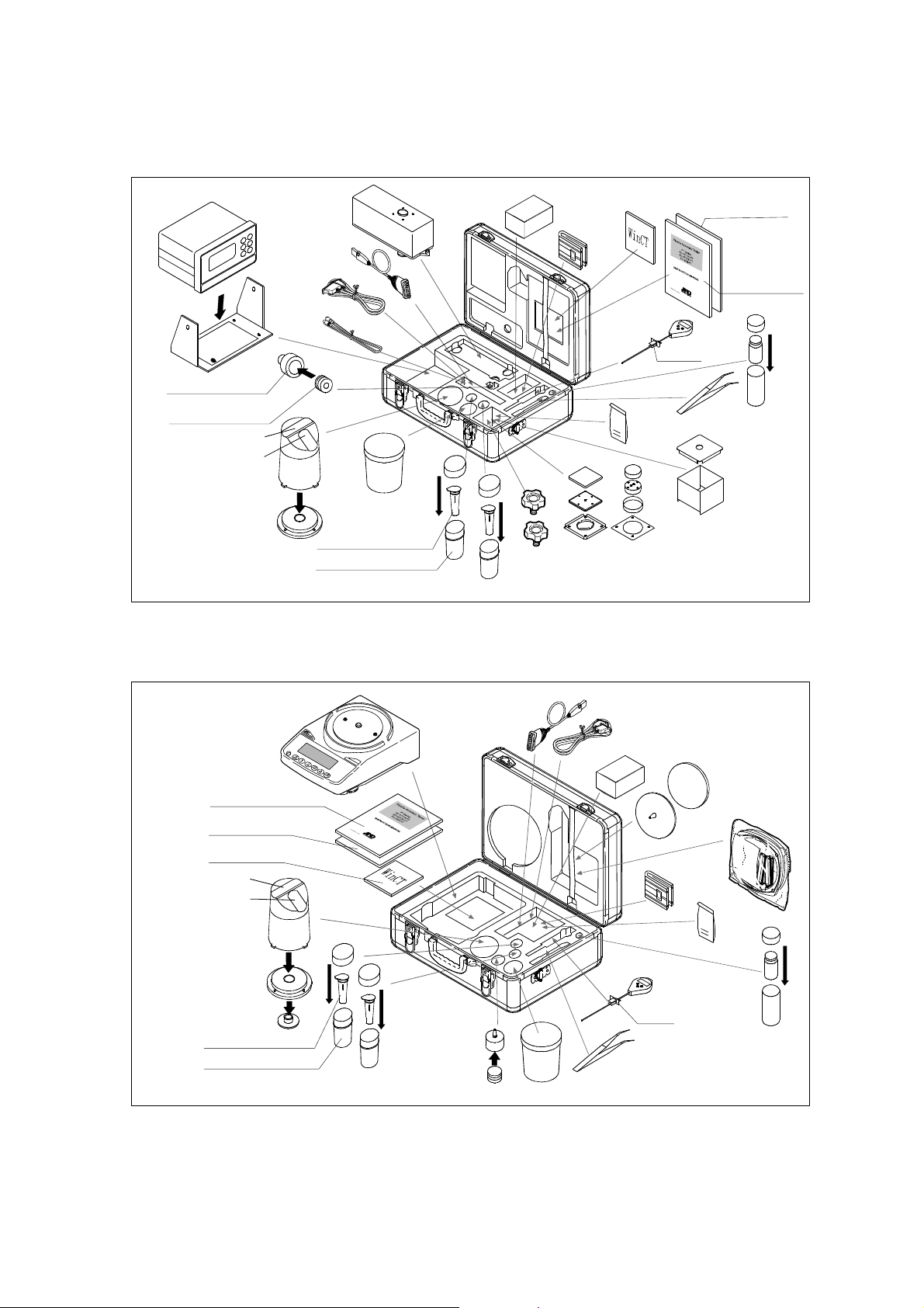
AD-4212B-PT / AD-4212A-PT
The connection cable provided as an accessory is one meter long.
Display
Stan d
USB converter
RS-232C cable
(25P-9P)
Connection
cable (1 m)
Weighing unit
Carrying
case
Sample cup holder
Sample cup holder
(30 mL)
(5 mL)
Cap A
Cap B
Evaporation trap
Evaporation trap
base
Test liquid cup
Capacity:5 mL (2 pcs)
Capacity:30 mL (2 pcs)
Sample cup
AC adapter
Angle
adjustment
knob
Shoulder
belt
WinCT-Pipette
(CD-ROM)
Thermometer
Thermometer
clamp
Tweezers
Key
Weighing pan unit
Instruction manual
for the balance
Instruction manual
for the tester
Calibration
weight
(50 g)
Breeze break
FX-300i-PT
Evaporation trap
Evaporation trap
Balance
Instruction manual
for the tester
Instruction manual
for the balance
WinCT-Pipette
(CD-ROM)
Cap A
Cap B
base
Fitting boss
Capacity:5 mL (2 pcs)
Capacity:30 mL (2 pcs)
Sample
cup
USB converter
Carrying
case
Sample cup
holder (30 mL)
Sample cup
holder (5 mL)
Test liquid cup
RS-232C cable
(9P-9P)
AC adapter
Thermometer
Thermometer
clamp
Tweezers
Weighing pan unit
Small breeze break
Shoulder
belt
Key
Calibration
weight
(100 g)
3
Page 6
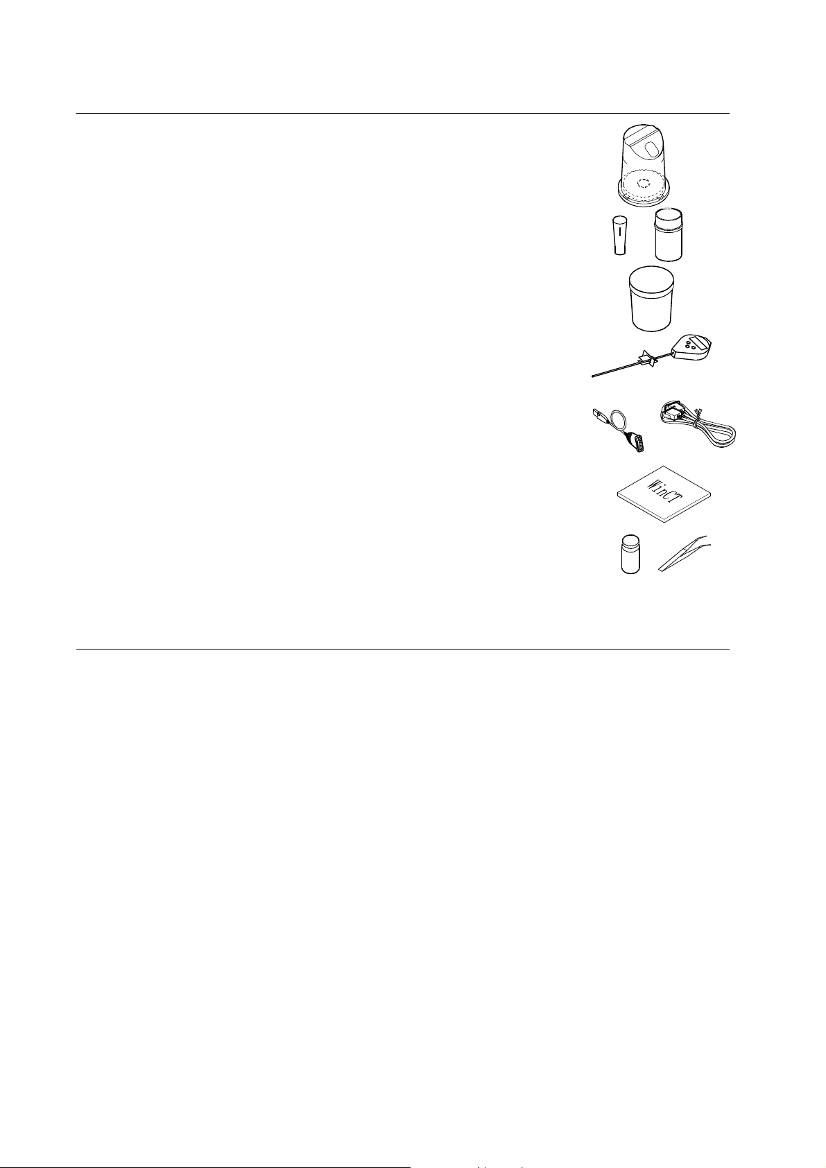
1-2 Description of Each Component
z Evaporation trap
A chamber to prevent the evaporation of the dispensed test liquid.
(Refer to “1-4 Function of the Evaporation Trap”.)
z Sample cup (Two types: 5 mL and 30 mL)
A cup to contain the test liquid dispensed from a pipette.
z Test liquid cup
A container to keep a test liquid such as distilled water.
z Thermometer (with a clamp)
Measures the temperature of the test liquid.
z RS-232C cable and USB converter
Connects to a PC (personal computer) to transmit the test values to the PC.
z WinCT-Pipette
Software for pipette accuracy testing to convert the test liquid mass
into a volumetric value.
z Calibration weight (with a pair of tweezers to handle the weight)
A weight to calibrate the balance.
1-3 WinCT-Pipette, Software for Pipette Accuracy Testing
Features
The mass value of the distilled water dispensed from a pipette is transmitted from the balance to a
PC. Using the temperature of the test liquid and the barometric pressure that are previously entered,
the PC calculates the conversion factor (Z factor) from a mass value to a volumetric value and
converts the mass value into a volumetric value automatically, using the Z factor.
The measurement results are compared with the specifications previously entered, to perform
judgment whether the pipette will pass or fail.
Besides the pipette volume, test numbers, test dates and pipette information (manufacturer, model,
serial number) can be recorded as test data. The test data, output to a printer or stored in the PC,
allows easy management of pipette accuracy and reduces errors due to data mismanagement.
The specifications of accuracy and repeatability can be entered either as an absolute value (μL)
or as a relative value (percentage to the pipette volume).
The mass value data from the balance can be transmitted to the PC either using a COM port or
using a USB connection. (For a USB connection, use the accessory USB converter.)
For testing various pipettes easily, multiple test conditions (pipette volume, number of
measurements and specifications) can be set previously. When multiple operators are set
previously, an operator can be selected easily as necessary.
4
Page 7
NOTE For detailed information on WinCT-Pipette, refer to “How to use WinCT-Pipette.pdf” in the
f
WinCT-Pipette CD-ROM.
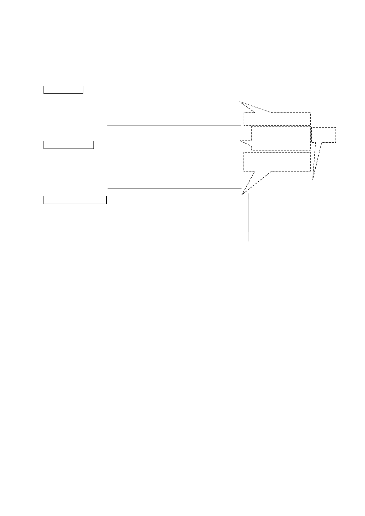
Main Window
When WinCT-Pipette starts up, the window below opens
Specifications
Enter the pipette volume, specifications of
accuracy and repeatability used for
pass/fail judgment.
Measured Values
Displays the mass values transmitted from the
balance and the volumetric values obtained
using the Z factor.
Measurement Results
Displays the measurement results and
judgment results.
The Z factor is automatically calculated using the values o
the distilled water temperature and the barometric pressure.
Measurement environment
Enter the ambient relative humidity,
the distilled water temperature and
the barometric pressure.
1-4 Function of the Evaporation Trap
In the pipette accuracy test using the gravimetric method, to obtain the mass of the test liquid, distilled
water is dispensed from the pipette into the sample cup installed on the balance. The obtained value,
however, is generally smaller due to evaporation loss of the test liquid. To prevent evaporation of the test
liquid, the evaporation trap is used. The ISO 8655 standard recommends that the humidity of the
measurement environment be greater than 50% RH.
Water is poured into the groove of the evaporation trap. This helps to maintain the humidity inside
the evaporation trap high and reduces evaporation. Using the evaporation trap reduces the
evaporation of the test liquid to about 25% or 0.05 mg per minute, compared with the value when the
evaporation trap is not used. This yields a measurement environment where there is no need to
consider measurement errors due to evaporation loss of the test liquid.
Another function of the evaporation trap is one as a breeze break, to prevent drafts in the
measurement environment from influencing the weighing operation and enable a stable weighing.
The evaporation trap is designed for an easy dispensing of the test liquid. The upper part has a
sloped surface so that the pipette can be inserted from obliquely above.
5
Page 8
A
2. ASSEMBLING THE TESTER
2-1 AD-4212B-PT / AD-4212A-PT
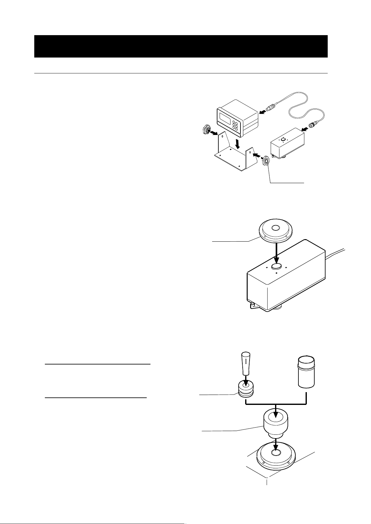
1. Place the weighing unit on a solid table. For details
on the installation site, refer to “3. PRECAUTIONS
BEFORE USE”.
Secure the display to the stand using the angle
adjustment knobs. Connect the display and the
weighing unit using the connection cable.
2. Install the evaporation trap base on the weighing
unit.
Stand
Evaporation
trap
base
Display
Connection
cable
Weighing
unit
ngle
adjustment
knob
3. Install the sample cup holder (30 mL) on the base.
When the 30 mL sample cup is used
Insert the sample cup into the holder.
When the 5 mL sample cup is used
Insert the sample cup holder (5 mL) into
the sample cup holder (30 mL), and then
insert the sample cup
:
:
5 mL sample
cup
Sample cup
holder (5 mL)
Sample cup
holder (30 mL)
30 mL sample
cup
6
Page 9
4. Install the lower part of the evaporation trap on the
weighing unit, mating the tabs with the holes on the
base.
5. Attach the upper part of the evaporation trap to the
lower part, mating the tab with the notch.
Lower part of
the evaporation trap
Tab
Hole
Upper part of
the evaporation trap
Tab
Lower part of
the evaporation trap
Notch
6. Adjust the direction of the evaporation trap so that the pipette insertion opening on the sloped
surface is faced to allow easy operation.
Pipette
insertion
opening
of the weighing unit
右 左
Facing to the right
Facing to the left
of the weighing unit
Pipette
insertion
opening
Cap A
7. Install cap A on the evaporation trap.
Remove cap B from the sloped surface.
Upper part of
the evaporation trap
Cap B
7
Page 10

2-2 FX-300i-PT
1. Place the balance on a solid table.
For details on the installation site, refer to
“3. PRECAUTIONS BEFORE USE”.
.
2. Install the fitting boss on the balance, then install
the evaporation trap base on the fitting boss.
3. Install the sample cup holder (30 mL) on the base.
When the 30 mL sample cup is used:
Insert the sample cup into the holder.
When the 5 mL sample cup is used:
Insert the sample cup holder (5 mL) into
Evaporation
trap
base
Fitting
boss
5 mL sample
cup
Sample cup
holder (5 mL)
30 mL sample
cup
the sample cup holder (30 mL), and then
insert the sample cup
Sample cup
holder (30 mL)
8
Page 11

p
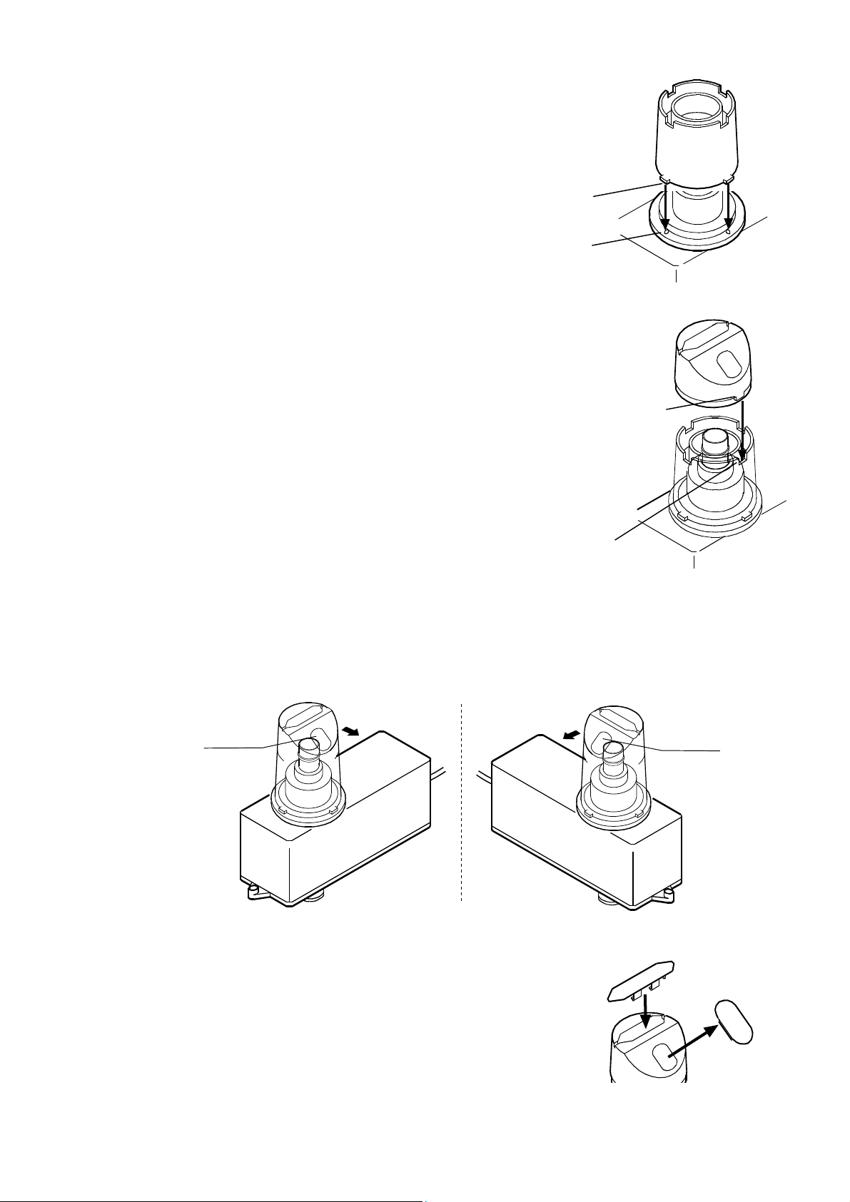
4. Install the lower part of the evaporation trap on the
weighing unit, mating the tabs with the holes on the
base.
5. Attach the upper part of the evaporation trap to the
lower part, mating the tab with the notch.
Lower part of
the evaporation trap
Tab
Hole
Upper part of
the evaporation trap
Tab
Lower part of
the eva
oration trap
Notch
6. Adjust the direction of the evaporation trap so that the pipette insertion opening on the sloped
surface is faced to allow an easy operation.
7. Install cap A on the evaporation trap.
Pipette
insertion
opening
Facing to the right
of the balance
Facing to the left
of the balance
右 左
Pipette
insertion
opening
Cap A
Remove cap B from the sloped surface.
Upper part of
the evaporation trap
9
Cap B
Page 12

3. PRECAUTIONS BEFORE USE
To get the optimum performance from the balance and acquire accurate weighing data, note the
following, especially when using the AD-4212B-PT / AD-4212A-PT with a minimum weighing value of
0.01 mg / 0.1 mg.
Install the balance where the measurement environment is appropriate. The best operating
temperature is 15°C to 30°C ±0.5°C with greater than 50% RH.
Install the balance where it is not exposed to direct sunlight and it is not affected by air from
heaters or air conditioners. Especially be careful when using the AD-4212B-PT. It responds
even to very subtle air flow.
Install the balance where it is free of dust.
Install the balance away from equipment which produces magnetic fields.
Install the balance in a stable place avoiding vibration and shock. Corners of rooms (close to
pillars or walls) far from a passage way are best, as they are less prone to vibration.
The weighing table should be solid and free from vibration, drafts and as level as possible.
Level the balance by adjusting the leveling feet and confirm it using the bubble spirit level.
Before use, warm up the balance for the appropriate duration with nothing on the weighing pan.
AD-4212B-PT / AD-4212A-PT: one hour or more
FX-300i-PT: 30 minutes or more
Calibrate the balance before use or after having moved it to another location. Use the
accessory calibration weight for calibration. For details, refer to “7. CALIBRATING THE
BALANCE”.
Caution
Do not install the balance where flammable or corrosive gas is present.
10
Page 13

4. ANTI-STATIC TREATMENT
An anti-static treatment has been applied to the evaporation trap. Cleaning it with alcohol will reduce
the effect of the treatment.
If the evaporation trap has acquired a static charge, apply an anti-static agent or use the optional
AD-1683 DC static eliminator to remove the static electricity.
5. INSTALLING WinCT-Pipette
For detailed information on the WinCT-Pipette program, refer to “How to use WinCT-Pipette.pdf ” in
the WinCT-Pipette CD-ROM.
For installing WinCT-Pipette, refer to “Readme.txt” in the WinCT-Pipette CD-ROM.
System requirements
OS Windows XP SP2 or later
CPU Pentium or the equivalent, 1GHz or more recommended
RAM 512 MB or more recommended
Hard disk available space Approximately 50 MB
Display 1024 x 768 or more recommended
11
Page 14

6. CONNECTING A PC TO THE BALANCE
To make a connection between a PC and the balance, use the RS-232C cable or use both the
RS-232C cable and the USB converter.
6-1 Connecting a PC
When a PC COM port is used
When using the COM port of a PC to make a connection to the balance, use the accessory RS-232C
cable.
RS-232C interface
RS-232C cable
AC adapter jack
AC adapter jack
RS-232C interface
RS-232C cable
Personal computer Personal computer
AD-4212B-PT / AD-4212A-PT FX-300i-PT
Weighing unit
connection jack
When a PC USB port is used
When using the USB port of a PC to make a connection to the balance, use both the accessory
RS-232C cable and the USB converter (shipped in a separate package).
The USB converter, when connected to the USB port of a PC, adds a COM port to the PC. When
connecting the USB converter to the USB port for the first time, installing a driver is required. (Some
PCs may require a driver installation even when the USB port used is changed.)
The driver installation CD and the instruction manual are contained in the same package with the
USB converter. For instructions on installation, read the manual.
After driver installation,
connect the USB converter to the balance, using the RS-232C cable. Now a
COM port is added
NOTE Although the USB converter is shipped in a separate package, it can be placed in the
carrying case.
USB converter
Personal computer Personal computer
and communications between the PC and the balance is enabled.
RS-232C interface
RS-232C cable
AD-4212B-PT / AD-4212A-PT FX-300i-PT
AC adapter jack
Weighing unit
connection jack
12
USB converter
RS-232C cable
AC adapter jack
RS-232C interface
Page 15

6-2 Checking COM Port Numbers
COM port numbers vary depending on the PC used. Use the Windows Device Manager to check COM
port numbers.
NOTE When the USB converter is used, check the COM port number with the USB converter
connected.
1 Click [Start], [Settings] and [Control Panel].
2 Double-click [System].
3 Click [Hardware] and [Device Manager].
4 Double-click [Port (COM & LPT)]. COM port numbers will be displayed.
When the USB converter is used, “ATEN USB to Serial Bridge (COMx)” appears.
In the example below, the COM port number is 4.
The COM port for a personal computer is displayed as “Communications Port (COMx)”.
In the example below, the personal computer has two COM ports. Therefore, two COM ports
appear; “Communications Port (COM1)” and “Communications Port (COM2)”
Change the WinCT-Pipette COM port number to that of the COM port used.
Checking COM port numbers in [Device Manager]
13
Page 16

7. CALIBRATING THE BALANCE
For details on calibration, read the balance instruction manual in addition to this manual.
Before calibration, refer to “3. PRECAUTIONS BEFORE USE”. Especially when calibrating the
AD-4212B-PT / AD-4212A-PT with a minimum weighing value of 0.01 mg / 0.1 mg, make sure that the
installation environment is appropriate and the balance is warmed up for the appropriate duration.
7-1 AD-4212B-PT / AD-4212A-PT
1. Remove the sample cup, but leave two
sample cup holders (5 mL and 30 mL) inside
the evaporation trap, as shown to the right.
2. Press and hold the CAL key until Calout
is displayed, then release the CAL key.
3. When Cal 0 is displayed, press the
PRINT key to enter the zero point.
4. After the zero point is entered, the calibration
weight value 50 is displayed.
Remove the upper part of the evaporation
trap while holding the lower part of the
evaporation trap.
Place the accessory calibration weight on the
sample cup holder (5 mL).
Sample cup
holder (5 mL)
Lower part of
the evaporation trap
Sample cup
holder (30 mL)
Calibration
weight (50 g)
Upper part of
the evaporation trap
Tab
Notch
Attach the upper part of the evaporation trap
to the lower part, mating the tab with the
notch.
5. Press the PRINT key to calibrate the
weighing capacity. When end is
displayed, remove the calibration weight. The
balance will return to the weighing mode.
6. Place the calibration weight on the
holder (5 mL) to confirm that calibration
cup
has been completed successfully.
sample
14
Page 17

7-2 FX-300i-PT
(
)
1. Remove the 30 mL sample cup and leave
only the
the evaporation trap as shown to the right.
2. Press and hold the CAL key until Calout
is displayed, then release the CAL key.
3. When Cal 0 is displayed, press the
PRINT key to enter the zero point.
4. After the zero point is entered, the calibration
weight value 100 is displayed.
Remove the evaporation trap by holding the
lower part of the evaporation trap.
Place the accessory calibration weight on the
sample cup holder (30 mL) inside
sample cup holder (30 mL).
Attach the evaporation trap on the base,
mating the tabs with the holes.
Upper part of
the evaporation trap
Lower part of
the evaporation trap
Sample cup
holder (30 mL)
Tab
(4 in all)
Calibration
weight (100 g)
Base
Hole
4 in all
5. Press the PRINT key to calibrate the
weighing capacity. When end is
displayed, remove the calibration weight. The
balance will return to the weighing mode.
6. Place the calibration weight on the
holder (30 mL) to confirm that calibration
cup
has been completed successfully.
sample
NOTE The evaporation trap can be used as a breeze break.
Calibration can be performed, using the weighing pan and the breeze break provided
as accessories.
15
Page 18

8. PREPARATION BEFORE USE
The measurement environment recommended by ISO 8655 is as follows.
Temperature: 15°C to 30°C ±0.5°C Humidity: Greater than 50% RH
8-1 Filling the Evaporation Trap with Water
Remove the evaporation trap from the balance. Separate the upper and lower part of the evaporation trap.
Pour water into the groove along the circumference of the inner wall of the lower part of the evaporation trap,
using a wash bottle or a pipette, up to the center between the two lines on the evaporation trap.
NOTE When pouring water, use much care not to spill water around the fitting boss of the
balance weighing pan.
Wash bottle
Attach the upper part of the evaporation trap to the lower part and place the evaporation trap on the
balance or weighing unit.
It takes approximately 15 minutes for the humidity inside the evaporation trap to stabilize to about 85% RH.
The time required for the humidity to stabilize varies depending on the measurement environment.
Lower part of
the evaporation trap
Water level
reference lines
8-2 Preparing the Test Liquid
Pour distilled water into the test liquid cup.
Place the thermometer in the cup, using the clamp as shown below.
Leave as is to allow the temperature of the distilled water to stabilize. ISO 8655 recommends that
the test liquid be acclimatized to the measurement environment for two hours or more.
Thermometer
Insert the thermometer
into the cup so that the
Clamp
clamp is hooked on the
edge of the cup.
16
Test liquid cup
Page 19

8-3 Using the Thermometer
Part names
Front Back
1
ON / FAST
2
3
AUTO-OFF
MAX / M IN
7
5
1: LCD
2: ON/FAST button
3: MAX/MIN button
4: Sensor sheath
4
5: AUTO-OFF button
6
6: Sheath protector
7: Battery cover
Before use
One LR-44 battery is provided with the thermometer. It is for testing the performance of the
thermometer and may have a limited life. Before use, install the battery as described in “Replacing
the battery” below.
Replacing the battery
When the LCD becomes blurred, replace the battery as follows.
1. Place the thermometer on a table with the back
up. Using a coin, rotate the battery cover
anti-clockwise to remove it.
2. Remove the old battery.
3. Install a new battery, with the + side (flat side)
facing up.
4. Using the coin, reattach the battery cover.
NOTE • Be sure to face the + side up when installing a battery.
• Use the specified battery only.
• Do not disassemble, heat, short-circuit, dispose of in fire or attempt to recharge the
battery. It may explode or leak and cause personal injury.
• Keep the battery out of the reach of children. If swallowed, consult a physician
immediately.
• Follow the local regulations when disposing of a used battery.
• To keep the thermometer watertight, do not damage the rubber ring or remove it
from the battery compartment.
Battery cover
Battery (LR-44)
Coin
17
Page 20

Displaying modes
The thermometer has three display modes.
Displaying mode Display example
• Current temperature mode
Displays the current temperature.
• Max/Min temperature mode
Displays the latest maximum and
minimum temperatures that are
automatically stored in the thermometer.
• Auto power-off mode
Turns the power off automatically after six
or seven minutes of no operation.
Measuring the temperature
Maximum temperature
Minimum temperature
Follow the procedure below to measure the water temperature.
1. Remove the sheath protector from the
thermometer.
2. Press the ON/FAST button to turn the display on.
3. Insert the sensor sheath into the water.
4. The sampling interval is 10 seconds.
To speed this process, press and hold the
ON/FAST button for a sampling interval of every
2 seconds.
5. As the thermometer responds to the water
temperature, the displayed temperature changes,
stabilizes and then displays the water
temperature.
NOTE The thermometer detects the
temperature at the tip of the sensor
sheath. Do not expose parts of the
thermometer other than the sensor
sheath to the high or low temperature
of the test liquid.
AUTO-OFF
MAX / MIN
ON / FAST
ON / FAST
MAX / MIN
Water
Temperature
detection
Sensor sheath
AUTO-OFF
part
18
Page 21

Recalling the maximum and minimum temperatures stored in memory
With the current temperature displayed,
Current temperature
each pressing of the MAX/MIX button displays
Press MAX/MIN
the maximum and minimum temperatures in
turn.
Maximum temperature
Press MAX/MIN
Minimum temperature
To check the maximum and minimum
temperature during measurement, reset the
values in memory before measurement.
Press MAX/MIN
Resetting the maximum and minimum temperatures stored in memory
• Resetting the maximum temperature
Max. temperature
in memory
ON/FAST
Press and hold
Stores the current temperature
as the maximum temperature
• Resetting the minimum temperature
Min. temperature
in memory
ON/FAST
Press and hold
Stores the current temperature
as the minimum temperature
• Returning to the current temperature display
MAX/MIN
Min. temperature
in memory
Press
Turning the power off
1. Auto power-off mode
The thermometer has an auto power-off mode. To use this mode, press the AUTO-OFF button to
display “AUTO”. This indicates the thermometer is in the auto power-off mode. When no operation
is performed for six or seven minutes, the power is turned off automatically.
2. Turning the power off
To turn the power off immediately, with “AUTO” displayed, press the AUTO-OFF button.
19
Page 22

Cleaning the thermometer
For accurate temperature measurement, keep the temperature detection part clean.
Wash the thermometer softly in water. If contamination is hard to remove, clean the thermometer
with a lint free cloth moistened with water and a mild detergent.
Specifications
Sensor : Thermister
Measuring temperature range : -50°C to 260°C
Display resolution : 0.1°C
Accuracy : ±1.0°C (0°C to 60°C), ±2.0°C (-20°C to 100°C),
±2.5°C (-50°C to 100°C), ±3.0°C (-50°C to 150°C),
±3.5°C (-50°C to 200°C), ±4.0°C (other)
Sampling interval : Regular every 10 seconds
FAST every 2 seconds
Water protection : JIS IPX7 (Endures a 30-minute immersion in a water depth of 1
meter at room temperature)
Power source : LR44 battery 1 piece
Battery life : Approx. 1 year
Operating environment : 0°C to 40°C, 75% RH or less, non-condensing
(Excluding the sensor sheath)
Storage environment : 0°C to 50°C, 75% RH or less, non-condensing
Sensor sheath dimensions : φ2.80, approx. 110 mm
Dimensions/mass : 176 x 40 x 16 mm, approx. 25 g (including the battery and sheath
protector)
Standard accessory : Sheath protector, battery
20
Page 23

9. MEASUREMENT
9-1 Measuring Procedure
Using the predetermined pipette volume, perform the measurement the specified times.
ISO 8655 recommends ten measurements for each for the volumes described below.
z At the nominal volume of a fixed volume pipette
z At the following three points of an adjustable volume pipette
1. 10% of the maximum volume or the lower limit of the adjustable volume range, whichever is
greater.
2. 50% of the maximum volume
3. 100% of the maximum volume
NOTE Pipette volumes and number of measurements can be changed.
9-2 Judging the Results
WinCT-Pipette converts the mass values into volumetric values, compares these with the
predetermined judgment standard and performs judgment whether the pipette will pass or fail.
z Judgment standard
The averaged value (exceeds / does not exceed) the specified maximum permissible error.
Repeatability (exceeds / does not exceed) the specified maximum permissible error.
21
Page 24

9-3 Example Causes of Measurement Errors
Evaporation of the test liquid
Evaporation of the distilled water dispensed from the pipette into the sample cup can be a cause of
measurement error.
To reduce errors caused by evaporation
zBe sure to use the evaporation trap. Using the evaporation trap, evaporation of the test liquid can
be reduced to 0.05 mg per minute (0.05 μL per minute).
zWith the AD-4212B-PT / AD-4212A-PT, use the display lock function. For details, refer to “10-2
Display Lock Function”.
Water temperature and barometric pressure
Correctness of the Z factor, that is used to convert a mass value to a volumetric value, depends on
the density by the water temperature.
The barometric pressure, even if changed in the range between 950 hPa and 1050 hPa, influences
measurements only by 0.01%.
Water temperature, if changed by 5°C, influences measurements by 0.11%.
To reduce errors caused by water temperature
zUse the correct Z factor. To obtain the correct Z factor, measure the water temperature using the
accessory thermometer and enter the value in WinCT-Pipette.
zFor a stable water temperature, allow the temperature of the test liquid to acclimatize to the
measurement environment for an appropriate duration of time (ISO 8655 recommends two hours
or more) before measurement.
Vibration
Vibration yields unstable measurement values.
To reduce errors caused by vibration
zInstall the balance in a stable place avoiding vibration and shock. Use a solid weighing table that is
free from vibration.
zIf the installation site is the second floor or higher, use the AD-1685 anti-vibration table.
22
Page 25

Air flow
Air flow in the measurement environment yields unstable measurement values
To reduce errors caused by air flow
zInstall the balance where it is not affected by heaters or air conditioners or where no drafts exist.
Especially when using the AD-4212B-PT / AD-4212A-PT with a minimum weighing value of 0.01
mg / 0.1 mg, use much care in choosing an installation site or cover the weighing unit.
Operator
An operator’s pipetting technique influences measurements.
To reduce errors caused by the pipetting technique
zLearn and use the correct pipette technique.
23
Page 26

10. AD-4212B-PT / AD-4212A-PT
The AD-4212B-PT / AD-4212A-PT is designed exclusively as a pipette accuracy tester.
Although the performance as a balance is the same as the AD-4212B / AD-4212A production
weighing unit, some of the specifications are different.
10-1 Factory Settings
When shipped, the factory settings of the AD-4212B-PT / AD-4212A-PT as a pipette accuracy tester
are as follows.
Unit
z Weighing unit: mg
z Minimum weighing value for the AD-4212B-PT: 0.1 mg
Press the SAMPLE key to switch to 0.01 mg as necessary, particularly for testing a liquid with a
volume of less than 100 μL.
Function table
Functions related to pipette accuracy testing are as follows.
Class Item and Parameter Description
Cond
Condition
ba5fnc
Environment
Display
trc
Zero tracking
5pd
Display refresh rate
ploc
Display lock function
Cp fnc
Comparator
Cp
Comparator mode
0
0
1
2
1
1
1
2
3
4
Factory setting
Fast weighing speed, sensitive value
1
MID.
2
Slow weighing speed, stable value
OFF
Normal
Strong
Very strong
3
5 times/second
0
10 times/second
OFF
0
ON
0
No comparison
Comparison, excluding “near zero” when stable or overloaded
Comparison, including “near zero” when stable or overloaded
Continuous comparison, excluding “near zero”
Continuous comparison, including “near zero”
FAST
SLOW
24
Page 27

10-2 Display Lock Function
To use this function, set “Display lock function (ploc)” to “ON (1)”.
Why use this function
This function is used to compensate time-elapsed errors caused by evaporation.
Even when the evaporation trap is used, an evaporation of 0.05 mg per minute (0.05 μL per minute)
will occur. This evaporation influences the measurement, particularly when the volume of the test
liquid is small. For such a situation, the display lock function is useful.
How this function works
After the test liquid is dispensed from the pipette, measurement starts. When the mass value is
stable, data is averaged. After a certain period of time, the averaged value is locked in the display.
Processing indicator
Blinking
Processing indicator
Stabilization indicator
Illuminated
Averaging process Locked display
NOTE The RE-ZERO operation unlocks the display.
25
Page 28

11. TROUBLESHOOTING
z Displayed values are unstable.
The AD-4212B-PT / AD-4212A-PT has a minimum weighing value of 0.01 mg / 0.1 mg and is
influenced by the measurement environment.
Measures to take
ß Use the accessory breeze break.
ß Referring to “3. PRECAUTIONS BEFORE USE”, check the measurement environment for
sources of drafts, vibration and static electricity.
ß The AD-4212B-PT with a minimum weighing value of 0.01 mg is prone to low-frequency vibration
such as shaking buildings. Particularly, earthquake, wind and changes in the barometric
pressure influence measurement. To avoid vibration, install the balance on the first floor, in the
corners of rooms (close to pillars or walls) far from a passage way.
ß Use the AD-1685 anti-vibration table.
ß Use the optional AD-1683 DC static eliminator or use the optional AD-1684 electrostatic field
meter if the cause of the unstable values may be due to static charges.
z Repeatability of the measurement values is low. The measurement values are not correct.
Measures to take
ß Referring to “3. PRECAUTIONS BEFORE USE”, check the measurement environment. Using
the accessory calibration weight, measure the balance repeatability and check the balance
performance.
ß Referring to “9-3 Example Causes of Measurement Errors”, check the measurement
environment for causes of errors.
z Balance error displays
Refer to the balance instruction manual.
26
Page 29

12. SPECIFICATIONS
AD-4212B-PT AD-4212A-PT
Weighing capacity
*1
Minimum weighing
value
Linearity
Repeatability
(Standard deviation)
Dimensions
Standard
accessories *3
AC adapter Please confirm that the AC adapter type is correct for your local voltage and
Power
consumption
Carrying case
dimensions
Mass
(With
all accessories
in a case)
±0.2 mg / ±0.05 mg ±0.3 mg ±0.002 g
Weighing unit: 80 (W) x 230 (D) x 200 (H) mm
Display (with a stand): 237 (W) x 150 (D) x 155 (H) mm
• Instruction manual
• Balance including the weighing pan unit, breeze break, AC adapter and AC
• Calibration weight with a pair of tweezers
• Evaporation trap
• Sample cup (30 mL x 2 / 5 mL x 2)
• Sample cup holder (30 mL / 5 mL)
• Thermometer
• USB communications kit (USB converter, RS-232C cable, Instruction manual)
• WinCT-Pipette (CD-ROM)
• Carrying case with a shoulder belt and a key
power receptacle type.
110 g / 31 g
0.1 mg / 0.01 mg 0.1 mg 0.001 g
0.1 mg / 0.05 mg 0.15 mg 0.001 g
adapter ID label
Approx. 7.6 kg Approx. 7.2 kg Approx. 6.4 kg
*2
Approx. 11VA (supplied to the AC adapter)
470 (W) x 150 (D) x 355 (H) mm
110 g 320 g
FX-300i-PT
193 (W) x 262.5 (D)
x190 (H) mm
*1 When the balance weighing pan is used.
*2 The AD-4212B-PT is equipped with a smart range function. When the minimum weighing value is
set to 0.01 mg and the mass value exceeds 31 g, the minimum weighing value will switch to 0.1
mg automatically. Even under this circumstance, pressing the RE-ZERO key tares the value and
weighing with the minimum weighing value of 0.01 mg is available up to 31 g.
*3 The standard accessories for the AD-4212B-PT / AD-4212A-PT / FX-300i-PT are different from
those for the AD-4212B / AD-4212A / FX-300i.
27
Page 30

13. APPENDIX
The table below lists the relation between the ISO 8655 requirements and the PT series pipette
accuracy testers.
Pipette
nominal
volume
*4
(μL) ±% ±μL % μL mg
20 1.0 0.2 0.5 0.1
50 1.0 0.5 0.4 0.2
100 0.8 0.8 0.3 0.3
200 0.8 1.6 0.3 0.6
500 0.8 4.0 0.3 1.5
1000 0.8 8.0 0.3 3.0
2000 0.8 16 0.3 6.0
5000 0.8 40 0.3 15.0
10000 0.6 60 0.3 30.0
Daily inspection, simplified verification 1 *6
Maximum permissible error
Accuracy Repeatability
ISO 8655 requirements
Balance
minimum
weighing
value
0.01 AD-4212B-PT
0.1
*4 The maximum volume selectable for adjustable volume pipettes
Pipette accuracy tester
corresponding to the requirements
*5
AD-4212A-PT
FX-300i-PT
*5 The AD-4212B-PT can be used for the pipette volume range from 20 μL to 10000 μL.
*6 The minimum weighing value, 1 mg, approximately corresponds to 1 μL. If a pipette volume is
1000 μL, a test can be performed with a resolution of 0.1%. If 200 μL, 0.5%.
NOTE Pipette accuracy testing is performed using a high-resolution valance. Make sure that
the measurement environment is free from vibration, drafts and air from air
conditioners. For details, refer to “3. PRECAUTIONS BEFORE USE”.
28
 Loading...