

Page 1

ОМПГ^Щ©ТГО©М ffiQÄMMÄlL
owners-AD-8118A-V.3.a 90.11.14
A&D Company, Limited
Page 2

Table of Contents
Warranty..................................................................................................... Page 3
Compliance with FCC Rules...................................................................Page 3
Introduction
Welcome.....................................................................................................Page 4
Features..................................................................................................... Page 4
Specifications
Description of Paneis
Front Panel.................................................................................................Page 6
Rear Panel.................................................................................................Page 6
Accessories................................................................................................Page 7
Installation
Best Conditions for Installation..................................................................Page 8
Connection of Power Supply/Ground..
Connection of Serial Input...................................................................... Page 8
Serial Input Connection Table
Connection of Control I/O..........................................................................Page 10
Control I/O Connection Table....................................................................Page 10
Replacing the Printing Paper
Replacing the Ink Ribbon..........................................................................Page 12
............
...........................................................................Page 5
......................................................
...............................................................
....................................................................
Page 8
Page 9
Page 11
Setting
Setting the DIP Switches...........................................................................Page 13
Function Setting Mode..............................................................................Page 14
Time Setting Mode....................................................................................Page 16
Date Formatting Mode..............................................................................Page 17
Operation
Operating the Switch Keys........................................................................Page 18
Operating the Control I/O..........................................................................Page 19
Others.......................................................................................................Page 21
©A&D Co., Ltd..international DivisIon{1990)
AD-81 ISAJounal Printer Instruction Manual v.3.a
11/13/90 JCK
Page 3

Printing
Nornnal Characters....................................................................................Page 22
Enlarged Characters..................................................................................Page 23
Applications
Serial Inputs...............................................................................................Page 26
Connection to an Industrial Scale..............................................................Page 26
■>
Connection to an Electronic Balance.........................................................Page 27
Connection to Peripheral Devices.......................................................... Page 27
Connection to Other Devices.....................................................................Page 28
Dimensions
..........................................................!................................
Page 29
Appendix
Character Code Table
...............................................................................
Page 30
Page 2
owners-AD-8118A-V.3.3
Page 4

Warranty
Warranty rights vary from country to country but it is the general intention of
A&D Co., Ltd., to offer customers a one year warranty on this product from the
day it is purchased. In some countries consumer protection legislation states
that your dealer is responsible for offering a warranty and under these
circumstances please ^efer to your local dealer.
in the U.S.A. the product (if defective) should be returned, freight prepaid by
the customer, to A&D Engineering Inc. in California and in Europe the product
can be returned freight prepaid to A&D Instruments GmbH in Frankfurt, West
Germany. Elsewhere the product can be returned to A&D Co., Ltd. in Japan.
In any event please contact your nearest A&D office before shipping, to
confirm that the product is covered by this warranty. Simple repairs can be
carried out by your local dealer under warranty and this may be the fastest
method of solving your problem.
This warranty only applies to product failures due to defective materials and/or
workmanship. This warranty will be rendered invalid if, upon inspection, it is
found that the product was: Abused; used for a purpose for which it was not
designed: mishandled; placed in a hostile environment; repaired by
unauthorized personnel; improperly installed or not adjusted in accordance
with instructions given in this manual.
ij^i
If repair under warranty is confirmed by A&D, then the product will be repaired
(or replaced, at the discretion of A&D) and then returned to the customer at no
extra cost.
Compliance with FCC Rules
Please note that this equipment generates, uses and can radiate radio
frequency energy. This equipment has been tested and has been found to
comply with the limits of a Class A computing device pursuant to Subpart J of
Part 15 of FCC rules. These rules are designed to provide reasonable
protection against interference when equipment is operated in a commercial
environment. If this unit is operated in a residential area it might cause some
interference and under these circumstances the user would be required to
take, at his own expense, whatever measures are necessary to eliminate the
interference.
(FCC = Federal Communications Commissbn in the U.S.A.)
owners-AD-8118A“V.3.a Page 3
Page 5

Introduction
Welcome!
Thank you for your
This is an Instruction Manual for the AD-8118 A Journal printer. The
AD-8118A is a product of years of design, development, and in-field
testing. It is designed to withstand harsh environmental conditions - and
each printer is subjected to several levels of quality control before it leaves
the factory. Every care has been taken during the manufacturing process
of this printer to ensure that it will perform accurately and reliably for
many years,
The AD-8118A Journal Printer is mainly for use with A&D's industrial scales
and electronic balances. A highly reliable printer mechanism is perfect for
industrial use, a watchdog circuit prevents malfunctioning and the AD8118A is built solid to protect against noise influence. Easy to operate, the
Journal Printer provides fast dependable printing.
purchase
Features
□ Dot impact printing mechanism.
□ Can print 24 columns per line.
□ Easy connection to serial input cable.
□ Small DIN size body can be mounted on panel.
□ Cumulative total function by code.
□ Calendar/clock function.
□ A lithium battery provides cumulative total and calendar back-up
without AC power for approximately 6 years.
□ 60 mm paper used for large printing capacity.
Page 4
owners-AD-8118A-v.3.a
Page 6
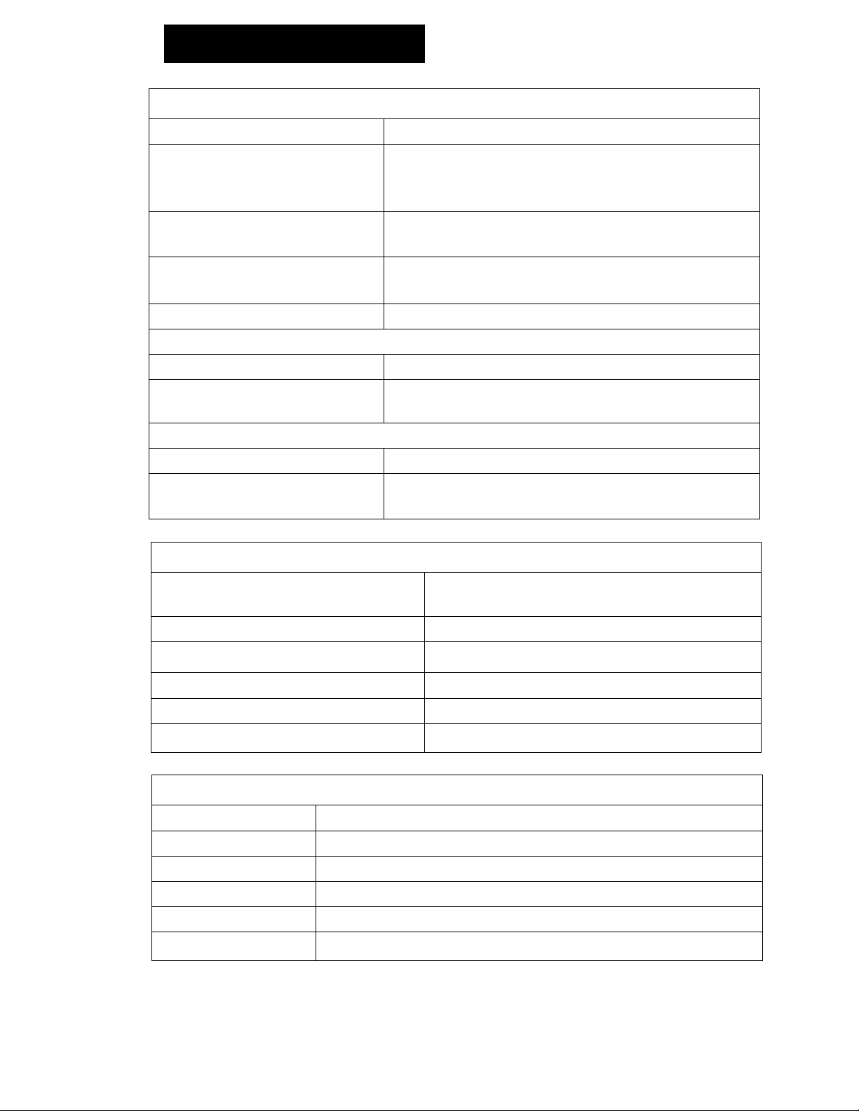
Specifications
Printer Specifications
Printing system
Printing width
>
Printing speed
Dimensions of character
Reiiability 1,000,000 lines
ink ribbon (ERC-09)
Color of character
Life
Printing paper (PP-137)
External dimensions 57.5 (W) X 60 (diameter) mm
Length
Mechanical type dot impact printer
24 columns/iine for 5 x 7 dot character
12 columns/Iine for 10 x 7 dot character
(enlarged character)
Approximately 1.7 iine/second
(internal processing time excluded)
1.7(W)x2.6 (H) mm
3.4 (W) X 2.6 (H) mm (enlarged character)
Purple
250,000 characters (varies depending on
environment)
Approximately 30m (an ending mark
appears approximately 1 m from the end.)
Generai Specifications
Power supply
Weight
Operating temperature range
Maximum humidity 80 %RH (non-condensating)
Physical dimensions
Dimensions of panel cut
100, 117, 220, 240V AC +10% / -15%,
50/60 Hz
Approximately 3 kg
-5°C to 40^C(23^F to 104^F)
192 (W)x185 (D)x96 (H) mm
186 +1.0/-0 X 92 +0.8/-0 mm
Input Specifications
Method
Baud rate
Data bits
Parity bit
Stop bit
Codes used
EIA RS-232C or 20 mA current loop (PASSIVE)
2400/600 bps
7/8 bits
1 (EVEN)/0
1
ASCII or JIS
owners-AD-8118A-v.3,a
Page 5
Page 7
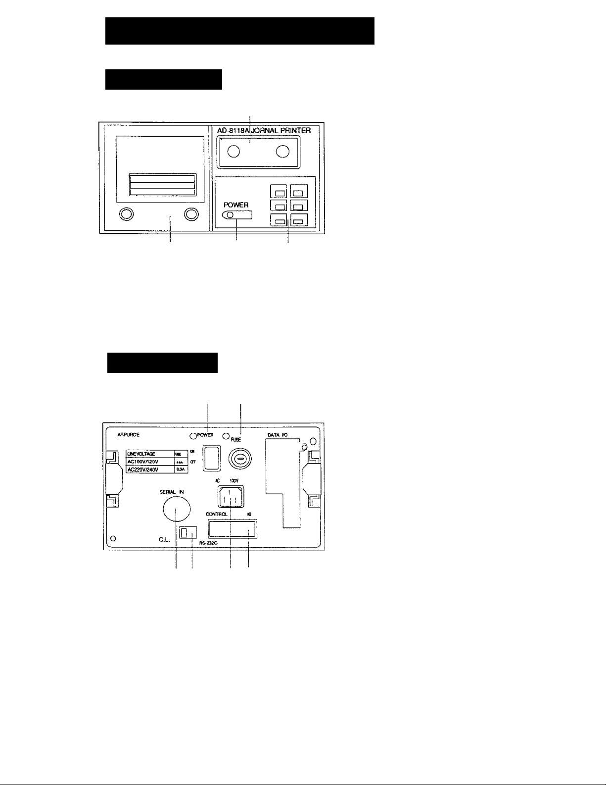
Description of Panels
Front Panel
© Cover for setting section
Remove this cover and use
the DIP switches to set,
otherwise keep it attached to
prevent dust from getting
inside.
@ Printer cover
Remove this cover to change
printing paper and/or ink
ribbon,
@
<D POWER indicator
This lights up when the power
is on.
® Operation keys
For operation, refer to
"Operating the Switch Keys," .
Rear Panel
Connector for power cable
Refer to "Connection of Power
Supply/Ground," .
© ®
(D ©
© POWER switch
Turn OFF when not using.
© Fuse
0.5A 100V to 120V{blow)
0.3A 200V to 240V(blow)
@ Standard serial input
connector
Input of RS-232C or current
loop for data.
Refer to "Connection of Serial
Input,".
® Select switch for input mode
This switch is used to select
RS-232C or current loop for
serial inputs. Refer to "Serial
Inputs,".
® Connector for control I/O
This is the I/O area that
controls the printer. Refer to
"Connection of Control I/O,".
Page 6
owners-AD-8118A-V.3.3
Page 8

Accessories
AC cable
Fuse
0.5A lOOVtO 120V{blow)
0.3A 200V to 240V(blow)
1
1
Printing paper (PP-137)
Ink ribbon (ERC-09 by Epson)
I/O connector
DIN connector
Rubber legs
1
1
1
1
4
owners-AD-8118A-v.3.a
Page 7
Page 9

Installation
Best Conditions for installation
Be careful when handling this unit because it is a precision electronic
device.
1) Don't install the AD-8118A in direct sunshine. Avoid places where
there are sudden temperature changes, vibrations, strong winds and
excessive moisture or dirt.
Also, keep away from conductive substances such as carbon powder.
If these substances get inside the unit errors can occur.
2) The best temperature setting is about 20°C (68*^ F) at 50% relative
humidity.
3) Be careful not to expose the unit to excessive noise or static electricity,
this may cause malfunctioning.
Connection of Power Supply/Ground
Earth the AD-8118A via the power cable to the rear terminal of your
1)
scale or balance. Don't plug it in directly to any other equipment. Do
not use it commonly with power devices.
If the local AC electricity supply fluctuates by more than ±10% an AC
2)
regulator must be used to stabilize the power supply. Do not use a
common source for the power lines.
NOTE: Do not turn ON the power at this time. Connect the power
plug after all other connections have been made.
Connection of Serial lnp>ut
The Serial input on the rear panel can be connected with either the RS232C input or the current loop input. Select the appropriate input with the
slide switch also located on the rear panel.
Direct Connection
The Serial Input can be connected with a standard serial output or current
loop on A&D Weighing Indicators.(ex. AD-4322A, AD-4323, AD-4324,AD4325A)
Page 8
owners-AD-8118A-v.3.a
Page 10
Using the Optional Interface
The Serial input can be connected with a RS-232C input or current loop
input using an RS-232C optional interface. This can be done with the FX,
FY, FR, FV, FW and AD-4316 or AD-4321. (If the option is provided with a
current loop output, it can be used as well.)
Note that these units^are equipped with outputs that can be connected to
the AD-8917, AD-8918, AD-8117 and AD-8118A externally.
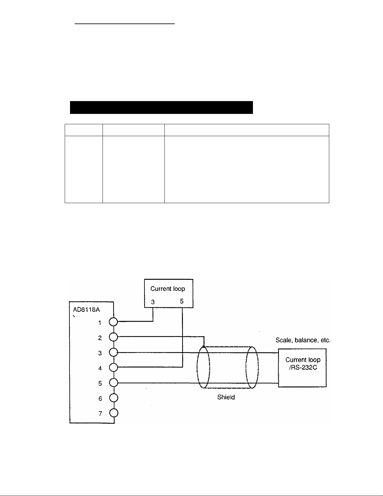
Serial Input Connection Table
Pin No.
1
2
3
4
5
6
7
O The Serial Input is commonly used for the RS-232C and the current
loop. On a RS-232C connection, pin No. 5 Is used as the signal
ground; connect the shield to pin No. 2.
O Signal lines using a twist-pair shielded cable should work better. This
is diagrammed below:
Abbreviation
C.LOUT
F.G
Ser. m+ Serial input + (TxD) /
GND
Ser.lN-
I.C
I.C
AD-8117, 8118A, 8917, 8918 etc.
Description
Current loop output ^
Frame ground /o 0\
Signal ground 1 J
Serial input - (SG)
For internal use
For internal use Viewed from rear panel
owners-AD-8118A-v.3.a
Page 9
Page 11

Connection of Control I/O
+v
Input
□ This is the interface circuit of the Control I/O .
□ Please use an optical isolator or relay.
□ The extension, or driving capacity of these relays is 24V 50mA DC
maximum.
□ The width of these inputs are at least 100msec.
Control I/O Connection Table
Pin No.
A 1
1 ■—1
2
2 2
3 4
4 8
5
10 5
6 20 6
7
40 7
8 80 “ 8
9 Printing command input
10
Paper feed command input 10
11
Addition command input
12
Subtotal printing command input
Description
Code input (BCD)
Pin No.
B 1
3
4
9
11
12
Grand total printing command input
Delete command input
Cumulative total delete command input
Input for disable printing time
Busy output
Printing announcement
N.C.
Output common
For internal use
Input common
Input common
F.G.
The Pins to change the Control I/O specifications are located on the rear
panel. See drawing below:
12
DODDODDOQDDD
D D D D D D D D D a D Q
/
Viewed from the rear panel
1
\
The inputs are operated by shortcircuits.The input is a pulse that has a coded
A
input. These pulse widths are 100 msec, or
B
longer.
The output is operated by the output
transistor turnnig ON.
Description
/h Note The data will only print when the "Input for disable printing time"
Pin # B-4 is shorted.
Page 10
owners-AD-8118A-v.3.a
Page 12

Replacing the Printing Paper
1, First, turn the power OFF.
I
----
1
o
0
j] Paper Roli
r
Front View
Side View
Side View
Front of Printer
Loosen the screws on the printer cover and
2.
draw out the printer unit.
Peel off the adhesive tape on the printing
3.
paper (PP-137) completely, insert the shaft
provided as an accessory and set the
paper. (Be careful of the Erection of the
paper.)
After setting the paper to the holder, take
4.
out the paper and insert it into the opening
labeled "A" on the printer through the lower
side of the roller, as shown to the left.
With the paper inserted, turn the right knob
5.
of the printer unit in the direction of the
arrow shown to the left; the paper should
come out the front.
oi.
Side of Printer
!f the paper fails to come out, check for a
bend or fold in the paper. If it is difficult to
insert, fold the top over a few centimeters.
If the ink ribbon needs adjusting turn the
knob of the ink ribbon to give tension to it.
Return the unit to its original position and tighten the screws on the
6.
printer cover.
Note 1: Do not apply excessive force to the printer unit. If normal, it
can be drawn out easily. If it is hard to take out return it once and draw
it out again. The guide may be damaged if excessive force is applied
vertically or horizontally.
Note 2: The printer is made of precision components and could be
damaged if metallic powder, water or other foreign substance get inside
the printer. Also be careful of static electricity when the printer is drawn
out..
If dust and other foreign substance get inside the unit, blow it out with
clean air. If the unit is used in a dusty environment consider using a
dust cover or air purge when not in use.
Note 3: A red mark will be printed approximately 1m before the end
of the roll of paper; replace the paper when you see this mark.
owners-AD-8118A-v.3.a
Page 11
Page 13

Replacing the Ink Ribbon
1. First, turn the power OFF.
2. Loosen the screws on the printer cover and draw out
the printer unit. Remove the printing paper. (Refer to
Front of Main Unit
"Replacing the Printing Paper," p. 10.)
3. Remove the printer cover carefully: it can be
detached from the unit by lightly lifting up.
Side of Main Unit
4. Remove the old ink ribbon by lifting it up when the
arrow position of the printer unit is pushed.
5. Set the new ink ribbon in place being careful not to
—TTT
À
__
Front of Printer
roll the ribbon. After the ribbon is in place, turn the
right knob of the ink ribbon in the direction of the
arrow shown in the figure to the left.
6. Reattach the printer cover by setting the bosses and
sliding the cover down.
7. Set the printing paper, see page 11.
8. Return the unit to its original position and tighten the
Printer Unit
screws on the printer cover.
Note 1 : Do not apply excessive force to the printer unit. If normal, it can
be drawn out easily. If it is hard to take out return it once and
draw it out again. The guide may be damaged if excessive force
is applied vertically or horizontally.
Note 2: The printer is made of precision components and could be
damaged if metallic powder, water or other foreign substance get
inside the printer. Also be careful of static electricity when the
printer is drawn out.
If dust and other foreign substance get inside the unit, blow it out
with clean air. If the unit is used in a dusty environment consider
using a dust cover or air purge when not in use.
Page 12
owners-AO-8118A-v.3.a
Page 14

Settings
Setting the DIP Switches
The DIP switches control the conditions of printing. Open the cover on the
front panel (refer to “Front Panel,“ p. 6) and set the DIP switches. The DIP
switch options are as follows:
Switch No.
1 Baud rate
Contents
2 Data bit
3
Printing mode Dump print
4 Printing form
5* Minus/unstabie Accepted
6
7
8
Printing characters Standard characters
Key input
Setting mode
2400bps
7bit (even parity check) 8bit (no parity)
Normal characters
Enabled
Normal mode
OFF
600bps
Standard format
Inverted characters
Not accepteddata
Enlarged characters
Disabled
Setting modechange
All switches are turned OFF without No.3 when shipped from our factory so
make changes according to your needs. Note that switch #5 is available only
in the standard format.
n
start M
LSS
0
1 2
3
data bit parity bit stop bit
4 5
MSB
6
ON
The DIP switch explanations are described beginning below:
Baud rate Switch #1
Baud rate is the speed of transmitting data, it can be changed by the DIP
switch #1. Choose either a faster 2400bps or normal 600bps speed.
Choose 600bps to avoid errors caused by the expansion of the cable.
Data bit Switch #2
Data bits are the bits used to transfer one character of data; 7 bits or 8
bits are available. Even parity is performed on 7bit data.
Printing mode Switch #3
Dumb printing is simply having al! print formatting controlled by an
external device. All function keys and inputs are disabled except for the
FEED key.
owners-AD-8118A-v.3.a
Page 13
Page 15
The Standard format results in data after the output from an A&O
industrial scale or electronic balance is internally processed and
formatted. Printing timing, cumulative total, etc. are taken, (For the input
data of the standard format, refer to "Applications," p. 21.)
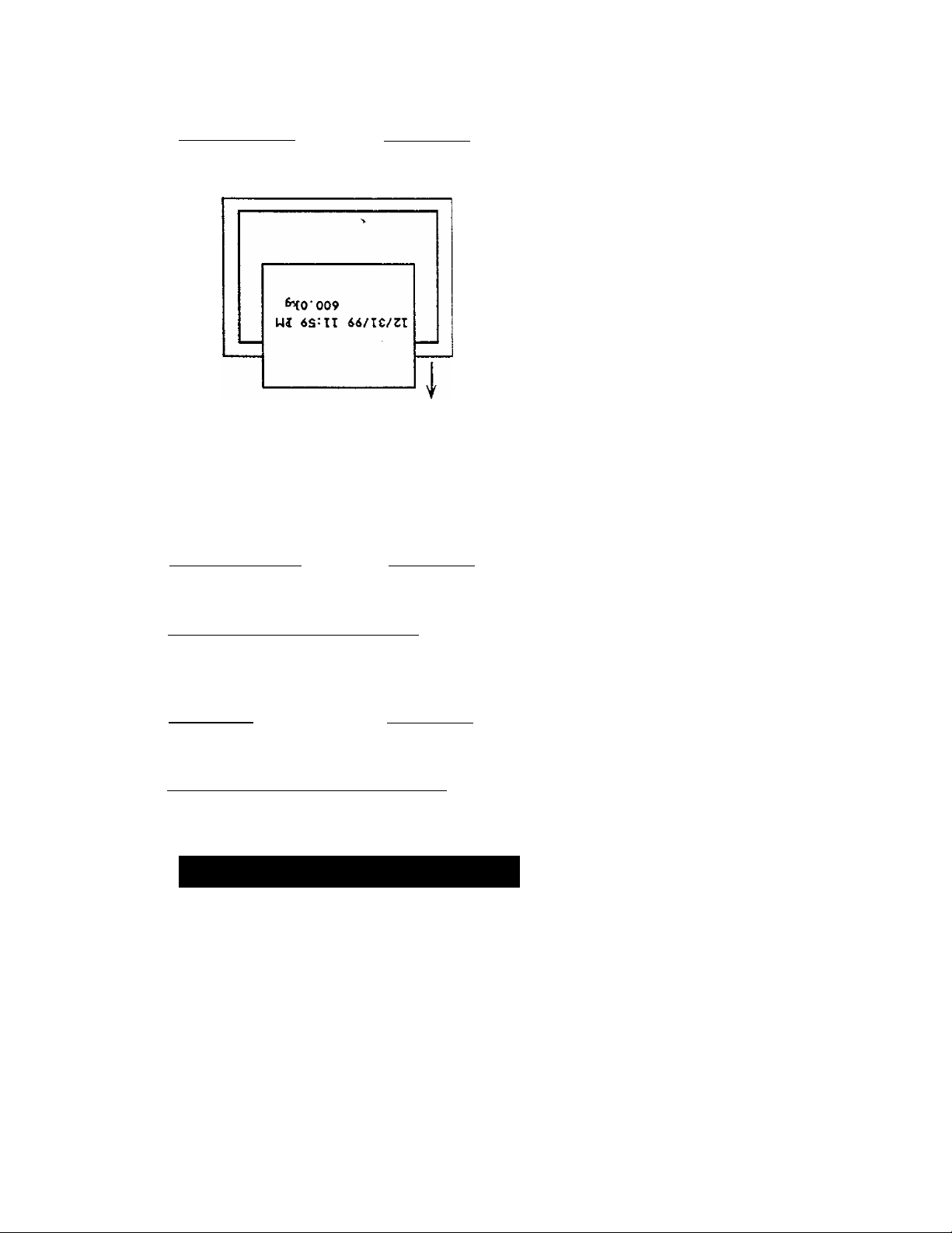
Printing form
Switch #4
Select the printing direction.
12/31/99 11:59 PM
600.0kg
Normal character Printing direction
inverted character Printing direction
When Normal characters are selected they seem to be inverted during
printing, but the printing process is the same as the input data process.
Inverted characters selected seem to be normal, but the printing process is
the opposite of the input data process.
Status printing Switch #5
Changes over to enable/disable the data at minus/unstable.
Printing character Switch #6
Choose either standard character size (5x7 dots) or
enlarged (10 x 7).
Key input
Switch #7
Enable or disable the key inputs from the front panel.
Setting mode change Switch #8
if this DIP switch is selected the unit is in the setting mode explained below.
Function Setting Mode
Setting mode can only be accessed when DIP switch #8 is turned ON.
Then, while pressing the SET UP key, press the M+.PRT.key at the same
time. The following message is printed:
FUNCTION 1 1
You are now in the Function mode, press the TOTAL key to change the
Function No, and same format used for printing. Press the M+.PRT. key to
increase the function level, press the CLEAR key to decrease the function
level.
Page 14
owners-AD-8118A-v.3.a
Page 16

The FEED key will advance the paper by one line and the PRINT key will
print the function message and the data currently in the setting format.
Press and immediately release the SET UP key to update and escape the
Function mode. The functions will be printed and the unit will return to
setting mode.
F1-1,F2-2,F3-1,F4-1
FUNCTION SET END
Function Mode Options
F1-Printing Mode
There are two types of FI printing modes:
(1) The Auto mode prints input data automatically. The printing
timing can be controlled either manually or by using the auto
printing mode.
(2) The Manual mode only prints when the PRINT key is pressed
or a command is input. The printing timing can be controlled on
the main unit if the device connected is set to stream.
Set value of FI
FI -1
Printing mode
Manual printing 1
Description
Adds and prints at addition printing,
(initial setting)
FI -2
Manual printing 2-
Adds only at addition printing.
FI -3 Auto printing Prints the data.
FI -4
Auto addition
Adds the data.
FI -5 Auto addition/printing Adds and prints the data.
F2- Lines to feed
Sets the number of feeding lines after printing the data or the
cumulative total by a number from 0 to 9. default is "2".
F3- Input mode
Select either gross weight, net weight, tare weight, or ail three. This
function is used when connecting a weighing indicator {ex. AD-4322,
AD-4323, AD-4325A) to several peripheral devices (external indicator,
etc.) (refer to ’‘Connection to Peripheral Devices,"). Otherwise, set to "1
(All enable)."
Set value of F3
F3-1 All enable (initial setting)
F3-2
F3-3
F3-4
owners-AD-8118A-v.3.a
input mode
Gross weight
Net weight
Tare weight
Page 15
Page 17

F4- Statistics mode
This mode can get maximum data .minmum data ,average data
.standard deviation, sample range of cumulated data and prints out
these. The Statistics caluclates all data no concernning with code
data.
Set value of F4
F4-0
F4-1
No caluclation of statistics (initial setting)
Sample deviation (an-i)
mode
F4-2 Standard deviation (an)
Time Setting Mode
Press the TOTAL key while at the same time pressing the SET UP key.
Now change the date and time to their correct settings. You will be
prompted with the following screen:
10/26/90 2:35 PM
A
To set the date and time use the following keys:
TOTAL key
M+.PRT key
Shifts the mark to the right, the mark indicates
which input can be changed.
Increases the number.
CLESR key
SET UP key
Decreases the number.
Press the SET UP key when done. This stores the date
and time to memory and the following message is
printed:
10/26/90 7:35 AM
CLOCK SET END
If any set value is wrong a message is printed, the value is not stored and
the unit remains in the time setting mode. Set the value again.
10/66/90 7:35 AM
A
CLOCK SET ERROR
Page 16
owners-AD-8118A-v.3.a
Page 18

Date Formatting Mode
You can select from the following date formats:
American type:
European type:
Japanese type:
6/22/90 10:47 AM
22/6/90 10:47 AM
90*6*22* 10*47* AM
To change date format:
Step 1
Step 2
Turn off the power switch on the rear panel.
Turn back on the power switch while pressing the SET UP
key and M+.PRT key at the same time.
Step 3
Press the CLEAR key to rotate through the three types. The
type selected will be printed as the CLEAR key is pressed.
American type
European type
Japanese type
<or>
<or>
U.S.A.
EUROP
JAPAN
Step 4 Turn off the power switch.
Step 5 Everything in Setting Mode has been saved,
switch #8 to the OFF position.
Return DIP
owners-AD-8118A-v.3.a
Page 17
Page 19

Operation
Operating the Switch Keys
PRINT FEED
SET UP M+.PRT
TOTAL CLEAR
□
CLEAR key
FEED key
PRINT* key
M+.PRT* key
Press M+.PRT key while pressing the this key to delete
the last data from the cumulative total. The following is
printed;
Press TOTAL key while pressing the this key to clear the
cumulative total and number; the following is printed:
Press this key to advance one line.
Hold it pressed to feed continuously.
Press this key to print a line of data
input. If no data is input within 3
seconds, "T ERROR" will be printed. If
the format does not match, "F ERROR"
will be printed.
Press this key to add an input data
before printing. If no data is input within
3 seconds a "T ERROR" is printed. If
the format does not match, "F ERROR"
is printed.
^CANCEL
^CLEAR
TOTAL key
SET UP key Press this key to set functions, etc. in the setting mode.
The keys marked with "*" are disabled in Auto printing mode. In Dump
Press this key to print the cumulative total (grand total)
separating the total weight by code and the gross total
weight.
Refer to "Function Setting Mode," p. 14 for details.
printing ail functions, other than the FEED key and the
SET UP key, are disabled.
Page 18
owners-AD-8118A-v.3.a
Page 20

Operating the Control I/O
Inputs
Code
Print
command*
Paper feed command
Addition print command *
Subtotal
printing
command
Grand total
printing
command
The value is printed on the left side of the paper when
addition printing is done. This value is stored with the
we^ht value and can be retrieved by code as well.
This code is not printed if the value is "00," only
numbers from 01 to 99 can be used.
When this input is negative low (short), the first data
input within 3 seconds is printed.
This command advances the paper one line, negative
low(short).
When this input is negative low(short), the first data
input within 3 seconds is added and printed.
This command prints the subtotal value and clears after
printing.
This command prints the grand total value and does not
clear the subtotal or grand total after printing.
Delete
command
Cumulative
total delete
command
Input for
disable
printing time
Outputs Busy
Printing This output is turned ON when the unit is printing,
announcement Control inputs are not accepted during this time.
This command deletes the last added data from the
cumulative total value and then prints the message
"^CANCEL". It is unable to perform this command if
there is no cumulative total value.
This command deletes the cumulative total value and
then prints the message "¥CLEAR". It is unable to
perform this command if there is no cumulative total
value.
Time printing is disabled while this input is ON. Once
OFF, the time printing is preformed once more on the
next printing time. In cumulative total printing, time
printing is preformed regardless of the input.
This output is turned ON when the data buffer exceeds
75 lines.
Therefore, enter the control input when this output is
OFF.
owners-AD-8118A-v.3.a
Page 19
Page 21

The inputs marked with are disabled in Auto printing mode. In Dump
printing, all functions except paper feed are disabled.
Each command input is judged at the negative edge and actuated only
when it is turned ON.
Input is accepted when turned ON (short-circuited) continuously for 100 ms
or longer.
Page 20
owners-AD-8118A“V.3.a
Page 22

others
Printing buffer
This unit has a printing buffer of 80 lines. If data can not be printed the
data is stacked in this buffer and cleared as the printing progresses. If
this buffer exceeds 75 lines the "Busy Output" from the I/O is turned ON.
"B ERROR" is printed^ once when the buffer exceeds 80 lines. The
printing speed is 1.7 iines/sec, do not input the data faster than this
speed.
Error printing
This unit recognizes the foilowing errors and prints them;
Error printing
T ERROR
U ERROR M
S ERROR *2
O ERROR
F ERROR
I ERROR
B ERROR
R ERROR*3
*1 This message prints the weight value and accepts to the cumulative
total.
A time out in manual printing.
Appears when the unit is different than the fast data unit in
cumulative total mode
Appears when the cumulative total weight is too much.
Appears when an input is too much.
Appears when the data format does not match.
Appears when needless data (-, unstable data) is input
Appears when the printing buffer is activated.
Appears when numbers other than "00" to "99" areinput as a
code input
Description
*Z This message prints the weight value but does not add the data to
the cumulative total.
*3 This message prints the weight value and accepts to the cumulative
total as code No, 00,
Proceduer of power on
Frist plesase power on other insturments coneciing to this printer and
power on this printer, if you power on other insturments with this printer at
same time and use automatic print mode or dumb print mode, frist data
can not often caludates. In manual print mode, No problem after
inputting several data to this printer.
owners-AD-8118A-v.3.a Page 31
Page 23

Printing
Normal Characters
Normal printing
Greater Code
8^11/99 8S00 PiH
CD99 (3S+ 200.0kg.
Code number
-Weight value
Error code is printed from
prior Error code.
Code priority as follow :
O ERROR>S ERROR>U
ERROR>F ERROR>l ERROR
Reference page 21
Addition printing
S/n/99 8:90 AM
# ,1 CD99 9S+ 200,0kg
A
Cumulative total counting number
Subtotal printing
Error code
3U^ TOTAL
8/1 10:05 PM
0' IT 50.02kg-
CD 1 IT 3.012kg
CD99 IT 200.0kg
3T \ 253.032kg
Number of times
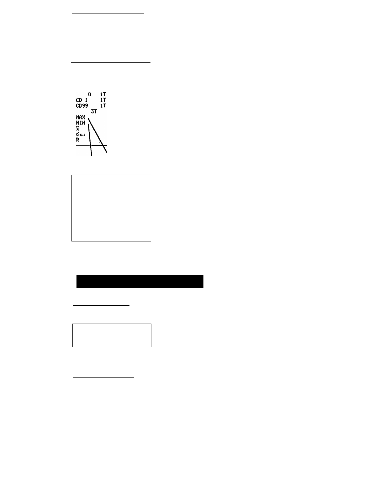
SUB TOTAL
8/11/99
CD 1
0)99
MAX V
MiH X 3.812kg
10:06 PM
0 IT
IT
IT
3T 253.032kg-
X \ 84.344kg_
tfn-l \ 182.S81Sk9^
R \ Vl^6.9S8kg,
50.02 kg ^
3.812kg
200.0kg>
200kg
Minimum data
SUB
8/11/99 10:07 PM
CD 1 IT
CD9.9 IT 200,0kg-
MAX V
MIH
^ w
TOTAL
0 IT
3T 253.032kg-
(1« \ X
50.02kg*
3,012kg
3.012kg
84,344kg
84.0027kg
V 196.983kg
Maximum data
Minimum data
Cumulative total by code (times : 4 digits,
cumulative total : 9 digits)
K
—Gross cumulative total (times : 6 digits,
cumulative total : 11 digits)
Pumulative total by code (times : 4 digits,
cumulative total: 9 digits)
/
Gross cumulative total (times : 6 digits,
cumulative total: 11 digits)
— Average of data
■—Sample deviation
^Range of data
Maximum data
Cumulative total by code (times : 4 digits,
cumulative total : 9 digits)
/
200kg
Gross cumulative total (times ; 6 digits,
cumulative total: 11 digits)
— Average of data
Standard deviation
Range of data
Cumulative total by Code is not
Printed, when only 'Code
No.OO' is entered, and No other
Code No is followed. (Control
I/O is not connected).
Page 22
owners-AD-8118A-v.3.a
Page 24
Grand Total printing
GRAND
9/11/99 18:05 PM
CO 1 IT 3.012k9
C099 IT
3T
GRAHD TOTAL
8/11/99 10:06 PM
TOTAL
0 IT
Maximum data
Minimum data
GRAND
8/11/99 10107 PM
0
CO 1
CD99
3T
MAX
V
MIN
\
X
\
R
A_
TOTAL
IT
IT
IT
\
Maximum data
Minimum data
(
Cumulative total by code (times : 4 digits,
50.02kg-
200.0kg-
253.032kg-
cumulative total: 9 digits)
;/■
■Gross cumulative total (times ; 6 digits,
cumulative total: 11 digits)
^Cumulative total by code (times : 4 digits,
0.02k9. /(
50
.0l2k9 f
3.
200
253.032kg—Gross cumulative total (times : 6 digits,
200kg ' ®
3.012kg
84.344kg
102.8S18kg
196.9S8kg
cumulative total : 9 digits)
cumulative total: 11 digits)
-Average of data
■Sample deviation
‘Range of data
.Cumulative total by code (times : 4 digits,
50.02kg-
3.012k9
280.0k9^
253.032kg-
200 kg
3.012kg
84.344 kg-
34.0027kg-
196,988kg-
cumulative total: 9 digits)
-Gross cumulative total (times : 6 digits,
cumulative total: 11 digits)
—Average of data
■—Standard deviation
Range of data
Enlarged Characters
Normal Printing
/Code number
8/11.^ >
GS-+-
Addition Printing
8/11
GS-*~
am
2©0.0k-3
Cumulative total counting number
00 AM
8i
COS'S«
20©.0
owners-AD-8118A-v.3.a Page 23
Page 25

Subtotal Printing
Error code
SUE/ TOTAL >
S/1l/99>
CD 1
CD33
40:05 PM X
k
D IT^ •
50- 02 kg
3- 012kg
200- 0 kg■
3T
253-032kg
3UB XOTAU
8/11/99 10!06 PM
CD 1 IT
S0. Q2 k*3
3.012
200. ©k-9
3T
253- 032 k-S
MAX
MIN
>?
CS"
102-SS10 kg
R
3-012 k^
- 34-4^ kg
133-3sakg
Number of times
IT
IT
cumulative total: 11 digits)
o IT
^Cumulative total by code (times : 4 digits,
j cumulative total: 9 digits)
IT
Gross cumulative total (times : 6 digits,
cumulative total; 11 digits)
200k-Si
Maximum data
Minimum data
Werage of data
Sample deviation
Range of data
3Ue TOTAL
3/11/99 10:07 PM
O IT
50-02kg
CD 1 IT
3-012kg
CD33 IT
200-0kgH
3T
253- 032kg
MAX
200 kg
MIN
_ 3-012kg
X
34- 344 kg
CT rt
S4-002T kg
R
136. - 333 kg
Cumulative total by code (times : 4 digits,
cumulative total: 9 digits)
r
Gross cumulative total (times : 6 digits,
y
cumulative total : 11 digits)
— Maximum data
— Minimum data
•Average of data
Standard deviation
Range of data
Page 24 owners-AD-8118A-v.3.a
Page 26

Grand Total Printing
aRAND TQTi^L.
3/n>^9 18i0S PH
CD 1 XT
O IT
•l—* K ^SmF
3-©X2k3
1T
200« ©k-g
3T
233. 032
0Ri=^HD TOTAU
S/U/9S 18:06 PH
O XT
ise . 02 k-s
CD X XT
3. 0X2k-g
XT
200.0 k-g
MAX
MIH
5<
2S3.032kg
200 kg
3. 0 12 kg
04.344kg
d" tit-i
X02-asiekg
R
X00.aaskg
Cumulative total by code (times : 4 digits,
cumulative total: 9 digits)
Gross cumulative total (times : 6 digits,
cumulative total: 11 digits)
,Cumulative total by code (times ; 4 digits,
cumulative total: 9 digits)
_l^ Gross cumulative total (times ; 6 digits,
cumulative total; 11 digits)
Maximum data
Minimum data
-Average of data
Sample deviation
Range of data
GRAf4D TOTAi»
8^'Il/99 10:07 PH
O XT
S0- 02 kg
CD 1 IT
3-012 kg
CD3S XT
200-0kg
3T
233-032kg
MAX
200 kg
MIH
_ 3-012kg
04- H 344 kg
*3"
©4-0022kg
R
X ae.seskg
^ Cumulative total by code (times : 4 digits,
I cumulative total: 9 digits)
Gross cumulative total (times : 6 digits,
cumulative total: 11 digits)
Maximum data
Minimum data
Average of data
Standard deviation
Range of data
owners-AD-8118A-v.3.a
Page 25
Page 27

Applications
Serial Inputs
The serial input can be changed through the RS-232C to current loop by
the slide switch on the rear panel. Select either one depending on the
product being connected. The power for the current loop is supplied by the
receiving side.
When using the RS-232C the following cables are useable:
For current loop (DIN7P-DIN7P) Note 1:
KO : 359- 200
KO : 359- 400
KO : 359- 600
KO : 359- 800
KO : 359-1000
KO : 359-1200
KO : 359-1400
For RS-232C (D1N7P-DSUB25P):
KO
Hint: "KO : 359-200" is a 200 cm, or 2 m cable for the current loop.
Notel: When connecting option OP-03 (RS-232C option) from a FV or
FW, use a cable for the current loop.
Set the connected instrument to stream, auto print or manual
print mode. The command mode can not be supported. In
addition, if the standard format input is set through the unit,
inputs are not accepted on rare occasions. Set the unit to
Dump print in such a case.
360- 200
Connection to an Industrial Scale
The standard format of A&D industrial scales are as follows:
AD-4316 +
AD-4321 A/B +
AD-4322A
OP-04
OP-04
(OP-04) *2
AD-4323
AD-4324
AD-4325A
FV series +
FW series +
* 1 A unit with "+OP-XX" means that it is necessary to pair this option.
Page 26
(OP-04)
(OP-04)
(OP-04)
OP-03
OP-03
owners-AD-8118A-V.3 .a
Page 28

* 2 A unit with ”(OP-xx)" can connect to the standard serial output.
Please set the DIP switches according to the specifications of these units.
When connecting to an AD-4325A, cumulative total can be started by the
codes of the AD-4325A if set to the output of format with the correct code.
Set the printer mode on DIP switch #3 to standard format.
AD-4601 has RS-232C. Set print mode of RS-232C Function . you can
input standard format data. (The flow speed can't be input; In this case ,set
dump printing mode.) >
Connection to an Electronic Balance
The standard format of A&D's electronic balances are as follows:
EP
series
ER
series +
ET
series
FX
series
FY
series
FC
series
EK
series + OP-03
FR
series + о P-03
Set the DIP switches according to their specifications.
+ OP-03
OP-03
■ + OP-03
+ OP-03
OP-03
+
+ OP-03
Connection to Peripheral Devices
This unit has the functional ability to send outputs, as well as input data,
through the current loop. This allows connection to the AD-8916, AD-8917,
AD-8918, AD-8117 and AD-8118A.
For example, if two AD-8917's are connected, the setting of gross weight,
net weight and tare weight output through the serial output of an AD-4322A,
AD-4323 or AD-4325A can be achieved. The following application will then
be realized:
AD-4323, etc.
in the above example, the gross weight is displayed in the AD-8917 "A" and
the tare in the AD-8917 "B". Then the net weight data is printed on the
AD-8118A and the cumulative total is calculated. Note that this printer can't
be connected to more than two other units.
owners-AD-8118A-v.3.a
AD-8118A
Page 27
Page 29

Connection to Other Devices
if this printer is connected to a personal computer, a sequencer or any other
unit set this unit to the RS-232C and Dump print. Set the DIP switches
appropriately. For characters to print, refer to the "Character Code Table” in
the Appendix, p. 30. This unit only receives signals, it can't output control
signals, message, etc. Note that overflow of the data buffer is valid for
control I/O only.
The following codes have meaning as control signals:
ODH
........
Moves a character point to the beginning of the next line and
clears the specification of an enlarged character.
OEH
------
An enlarged character can be used with this signal.
14H
-------
If this code is input while in the enlarged character mode it
changes back to the normal character mode. This command is
ignored when in norma! character mode.
1BH
-------
This code is used in combination with the following two
characters as an auxiliary code:
>
1BH+44H Prints the year, month and day.
1BH+54H Prints the time.
Page 28
owners-AD'8118A-v.3.a
Page 30

Il^
Dimensions
186
SIDE VIEW
+ 1.0
+0.8
0
owners-AD-8118A-v.3.a
Page 29
Page 31

Appendix
Character Code Table
KEX.N
0
1 2
0
NUL
1
2
3
4
5
6
7
8
9
A
LF
B
C
CR
D
E
F
ESC
(SP) 0
1
11
^ 2
# 3
$
%
Q
1
{
)
*
+
f
-
/
3
1
4
5
6
7
8
9
:
/
<
=
>
7
4
5 6
P
0
A
Q
B R
C S c
D T
E
u
F V
w
G
H X
I Y i
J z
K
[
L %
M
1
N
-
0
7
8 9
P
q
r
s
t
u
V
w
X
y i
z
{
1
1
}
z
■
1 r
1
I
1
1
1
+
a
b
d
e
f
g
h
j
k
1
m
n
0
A B
i*
T
-i
i-
-
-
C D
E
F
1
1
T
L
J
r
V,
J
Don't use codes AO-^FF
Page 30
owners-AD-8118A-V.3 .a
Page 32

A&D Company Limifed
Oashalsu-NIssay Ikebukuro Bldg. 5F, 3-23*14 HigashWkebukufo, Toshima-ku, Tokyo 170 Japan
Telephone: (03) 5391-6123 Fax: {03} 5391-6129 Telex: 02422816 AANOD J
A&DWGINEOTNG,1MC.
1555 McCandless Drive, Mtipilas. CA, 95035 U.SA
Telephone: (408) 263-5333- Fax; (408) 263-0119
A8tD INSTRUMENTS GmbH
Lyoner Straße 36, 0-6000 Frankfurt/Main 71. West Germany
Telephone: (069) 666-7006 Fax: (069) 566-6831 Telex: 417 0586 ANDI D
A8cD MERCURY PTY LTD.
32 Dew Street, Thebarton. South Australia 5031 Australia
Telephone: (08) 352-3033 Fax; (08) 352-7409
 Loading...