

Page 1

' a
.-'" '1
DlMinMy(STOi
Weighing Indicator
i-'ii
® [:|f ;I^Ig
WM+PD4000173D
A&D Company, Limited
Page 2

■! <*K!
A This is a hazard aiert mark.
This mark informs you about tha operation of the product
of this manual may be photocopied, reproduced, or translated into another lianguage
without the prior writteri consent of A&D Company, Ltd,
Product specifications are subject to change without any obligation on the part of the
manufacture.
© 2005 A&D Company Ltd. Ail rights reserved;
Page 3

Contents
Compliance
1.1. к Compliance with FCC Rules
1.1.2, Compliance with European Directive
Introduction
Installation and Precautions
3.1.1. Installation and Precautions..........................................................................5
3.1.2. The Load Ceil Connections............................................................................5
3.1.3. Adjustment of the Load Cell Output............................................................ 6
3.1.4. Verifying Load Cell Output and Input Sensitivity...
3.1.5. Installing the Option Board.......................................................................... 7
Description of Panels and symbols
4.1.1. Front Panel Description............................................................................... 8
4.1.2. Rear Panel Description.................................................................................... 9
4.1.3. Other Displays and Symbols....
4.1.4. Accessories and Option OP"02.....................................................................10
Calibration
5.1.1. Items of Calibration Mode............................................................................. 11
5.2. Calibration Procedure.................................................................................... 12
5.2.1. The Whole Procedure................................................................................. 12
5.2.2. Preparation
5.2.3. Entering the Calibration Mode.....................................................................13
5.2.4. Minimum Division (Weighing Interval)........................................................14
5.2.5. Maximum Capacity
5.2.6. Zero Calibration
5.2.7. Span Calibration............................................................................................16
5.2.8. Exiting the Calibration Mode........................................................................17
5.3. Weighing Range Function
5.3.1. Setting Division and Range
5.4. Digital Linearization Function......................................................................... 22
5.5. Gravity Compensation Function
5.5.1. The Gravity Acceleration Table....................................................................24
5.6. Calibration Error Code List
.............................................................................................................
...........................................................................3
.............................................................
........................................................................................................ 4
...............................................................................
.......................................
........................................................................8
...................................................................
....................................................................................................... 11
....................................................................................................13
...................................................................................
..................................................................................... 15
...............................................................................
......................................
.................................................................... 23
...............................................................................25
.............
......................19
14
18
3
3
5
6
9
6.
6.1. Changing the Function Settings........................................................................26
6.2. F“Functions.................................................................................................... 27
6.3. CF“Functions................................................................................................... 32
AD4329 Weighing Indicator, instruction Manual, A&D Co„ itd. Page 1
Functions
............................................................................................................
26
Page 4

ш
I
I
7. Tare.,...,.,
; 7.1,1. Weighing Tare ......;^
7.1.2. Digital Input
7.1.3. ClearingTare............................................................................................... 33
8. Accumulation
8.1.1. Preparation and Specification
8.1.2. Display and Operation................................................................................. 35
9. Comparison
9.1. Comparator Output Relay (OP-02)
9.2. Upper/Lower Limit Comparison....................................................................... 36
9.2.1. Selecting Upper/Lower Limit Comparison................................................. 37
9.2.2. Condition formula for Comparison
9.2.3. Setting Upper/Lower Limit Values...
9.2.4. Example..................................................................................................... .38
9.3. Setpoint Comparison
9.3.1. Selecting Setpoint Comparison...................................................................
9.3.2. Description of Input parameters and Outputs
9.3.3. Setting the Parameters of Setpoint Comparison.
..........
........*....».......:............;.:.....;;....,.л...Л...:,...» 33
......
....................................
............................................................................................... 33
..................................................................................................... 34
.................................................................. 34
......................................................................................................... 36
..........
.......................................................
........................................................
..........................................................
...................................................................................
............................................
.......................................
33
36
37
38
39
39
39
40
10. External Control Input................................... .................................................. 41
11. Standard Serial Data Output (SER.OUT)
11.1.1. Data Format................................................................................................ 43
12. RS-232C Interface............................................................................................ 44
12.1.1. Specification............................................................................................. 44
12.1.2. Data Format................................................................................................ 45
12.1.3. Command Format
12.1.4. Command to Request Data
12.1.5. Commands to Control the Indicator..
12.1.6. Commands to Set Parameters
12.1.7. Related Functions.................................................................................... 49
13. Specifications
13.1. Dimensions.................................................................................................. 51
....................................................................................................
.................................................................................... 46
.....................................................................
.............................................................
...
..........................................
........................................................
........48
42
46
47
50
Page 2
AD-4329 Weighing indicator
Page 5

Compliance
1.1.1. Compliance with FCC Rules
Please note thaï this equipment generates, uses and can radiate radio frequency
energy. This equipment has been tested and has been found to comply with the
limits of a Class A computing device pursuant to Subpart J of Part 15 of FCC rules.
These rules are designed to provide reasonable protection against interference
when this equipment is operated in a commercial environment. If this unit is operated
in a residential area it may cause some interference and under these circumstances
the user would be required to take, at his own expense, whatever measures are
necessary to eliminate the interference.
(FCC = Federal Communications Commission in the U.S.A.)
1.1.2. Compliance with European Directive
C€ This appliance complies with the statutory EMC (Electromagnetic Compatibility)
directive 89/336/EEC and the Low Voltage Directive 73/23/EEC for safety of
electrical equipment designed for certain voltages.
Note: The displayed value may be adversely affected under extreme electromagnetic
influences.
AD-4329 Weighing indicator
Page 3
1. Compliance
Page 6

2. Introduction
□ The AD-4329 is a compact weighing indicator that amplifies the signal from a load
cell, converts it to digital data and displays it as a mass value.
a This indicator has the following performance:
Input sensitivity:
Maximum display:
Refresh rate of the display:
Input voltage range:........................
..........................
..........................
..............
...0.2juV/division.
10000 divisions (or 20000 divisions).
10 times/second approximately.
-1 mV ~+15 mV.
□ There are the following standard functions:
□ The upper/lower limit comparison to check a mass value.
□ The setpoint comparison for batching applications.
□ The accumulation function to totalize these mass values and to count the number
of accumulations.
a There are the following standard interfaces:
□ The standard serial output for a printer.
Q The RS-232C serial interface to communicate with a computer.
This interface can request weighing data, enter parameters and control the state
of the indicator.
□ The calibration function includes the following functions:
□ Setting of the minimum division (weighing interval) and the maximum capacity.
□ Zero and span calibration.
a The weighing range function of the multi-interval weighing instrument (scale).
□ Digital linearization function.
□ Gravity compensation function.
□ There are seven external input terminals controlled by the F function,
o The option OP-02 has three output relays used for the upper/lower limit comparison
and setpoint comparison.
2. Introduction
Page 4
AD-4329 Weighing Indicator
Page 7
3. Installation and Precautions
ЗЛ .1. Instailation and Precautions
The AD-4329 weighing indicator is a precision electronic instrument Handle the
Indicator carefully.
The operating temperature is -10t: to *f40t: (14“F to 104"^).
Do not install the scale in direct sunlight.
Misoperation or other problems may be caused by an unstable power source including
momentary power failrue or instantaneous noise. Use a stable power source.
Aa
Ad
Do not connect the power cord before the installation Is finished.
Please confirm that the local voltage and receptacle type are correct for your scale.
The jOperate/Standbvi key @ key) can not cut the power. The load cell and the internal
circuit are supplied with power in the standby state.
Use shielded cable for ail connections. Connect the cable shields to the shield
terminal or case as an earth terminal.
Earth ground the indicator. Do not Join the earth ground line with other electric power
equipment. There is an earth ground terminal at the power cord receptacle.
□
Do not install the scale in a place where it is af3t to be charged with static electricity,
or where the relative humidity is lower than 45%RH. Plastic and isolators are apt to be
charged with static electricity.
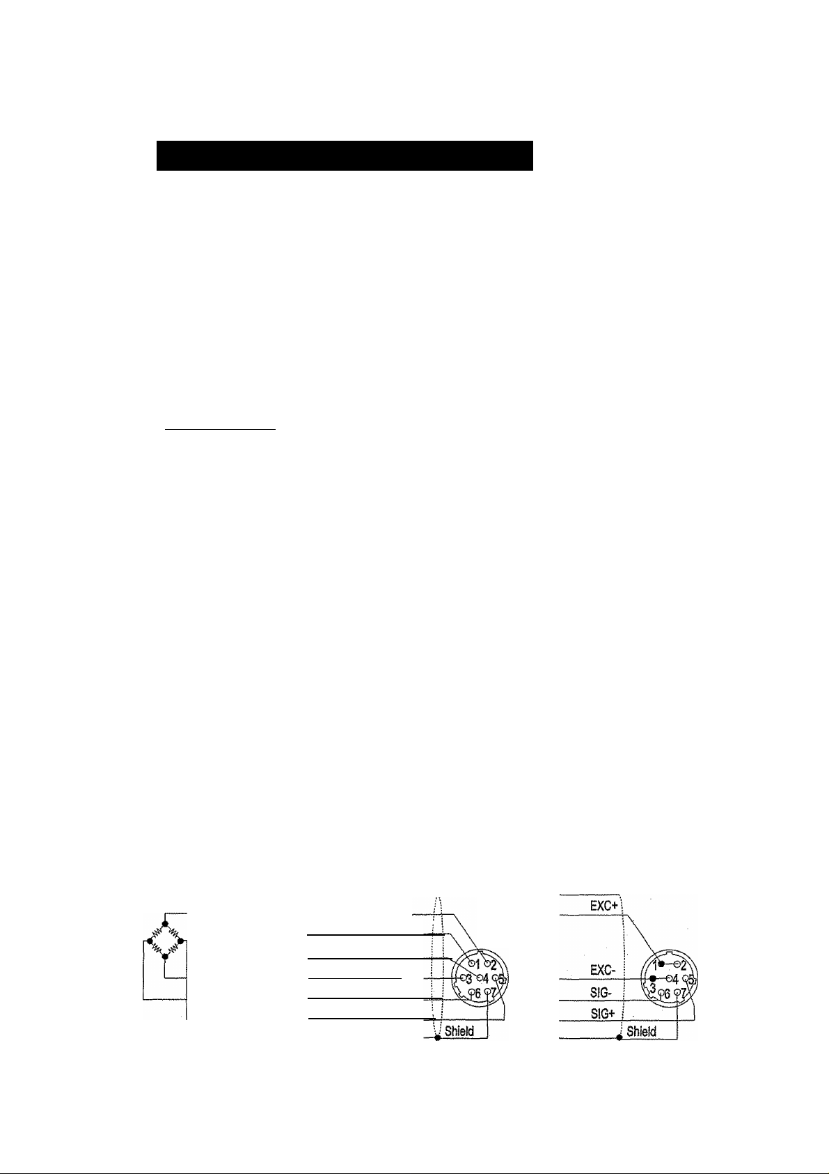
3.1.2. The Load Cell Connections
Connect the load ceil wires to the connector (receptacle), at the rear panel, using the
accessory load cell plug.
□
It is possible to connect a 4 wire cable that 1 pin"2pin and 3pin-4pin are shorted, if the
distance between the indicator and a load cell is shorter than 5m.
The output voltage of a load ceil is a very sensitive signal. Space the load cell cable
away from any noise source.
□
It is possible to connect eight 350Q load cells.
The load cel! drive is 5VDC ± 5% between EXC+ and EXC-, the maximum current 120mA.
EXC+
EXCSIGS1G+
Load ceii
AD-4329 Weighing Indicator
Cable Cable
i\
Positive Sense
Positive Excitation Input
Load Cell Plug
Negative Excitation input
Negative Sense
Negative signal Output
Positive signai Outpur
Standard
connection
Page 5
Available connection for
a cable shorter than 5m.
3. Installation and Precaution
Page 8
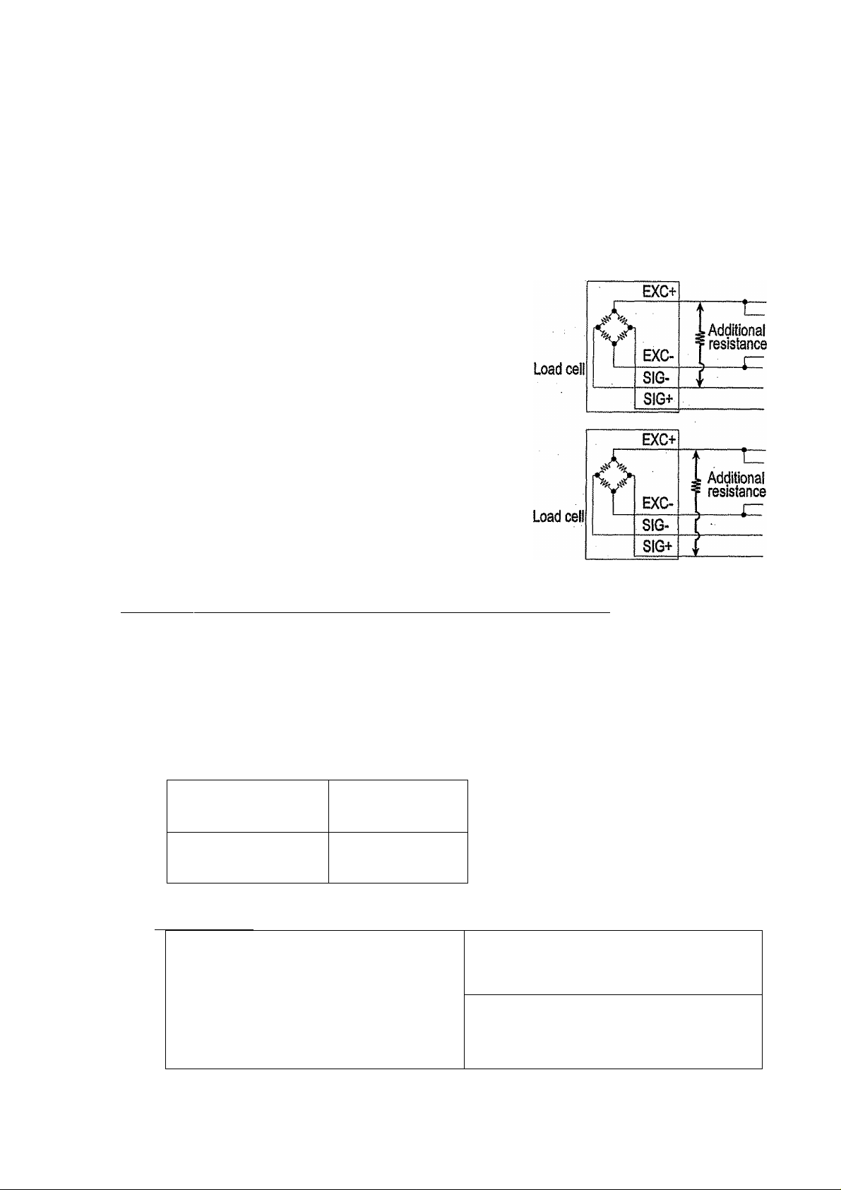
3.1.3. Adjustment of the Load Ceil Output
Caution a Use a inetaf film resistor in the range of 50kQ to 500kQ with a good
temperature coefficient when adding a resistor to adjust a load cell
output. Use as a large resistance value as possible in the range in which
zero adjustment is possible. Solder this resistor at a point near the load
cell or the indicator.
In Case of Reducing the Output Voltage
When the zero output is too large, add a resistor
between EXC+and SIG-.
in Case of Adding an Offset Voltage to the Output
When the zero output is too small, add a resistor
between EXC+ and S1G+.
3.1.4. Verifying Load Ceil Output and Input Sensitivity
The input sensitivity of the indicator is 0.2pV/division or more. Adapt to the following
inequality, when you design a weighing instrument using the indicator and load cell(s).
Caution □ A change in input voltage sensitivity is equivalent to a one division
change of the display. Select as large an Input voltage sensitivity voltage
as possible so that the weighing interval becomes stable,
a Consider the leverage If a lever is used.
Weighing instrument
using one load ceil.
, Weighing Instrument
using multi-load cell
Verification Example
Design;
Load cell
Rated capacity
Rated output
Excitation voltage
Weighing interval
Weighing capacity
E^tB^D
0.2 £
-----------A
E^Bh^D
0.2^——~
A^N
N=1
A=750 [kg]
8=3 [mVA/I
E=5000 [mV] regard the instrument as a good design.
D=0.05 [kg]
300 [kg]
A: Rated capacity of load cell [kg]
B: Rated output [mVA/]
D: Weighing interval [kg]
E: Excitation voltage [mV]
N: Number of load cells
6000*3*0.05 , ^
„ -j ^ 0.2. Therefore,
750
3. Insteilatìon and Precaution
Page 6
AD-4329 Weighing Indicator
Page 9
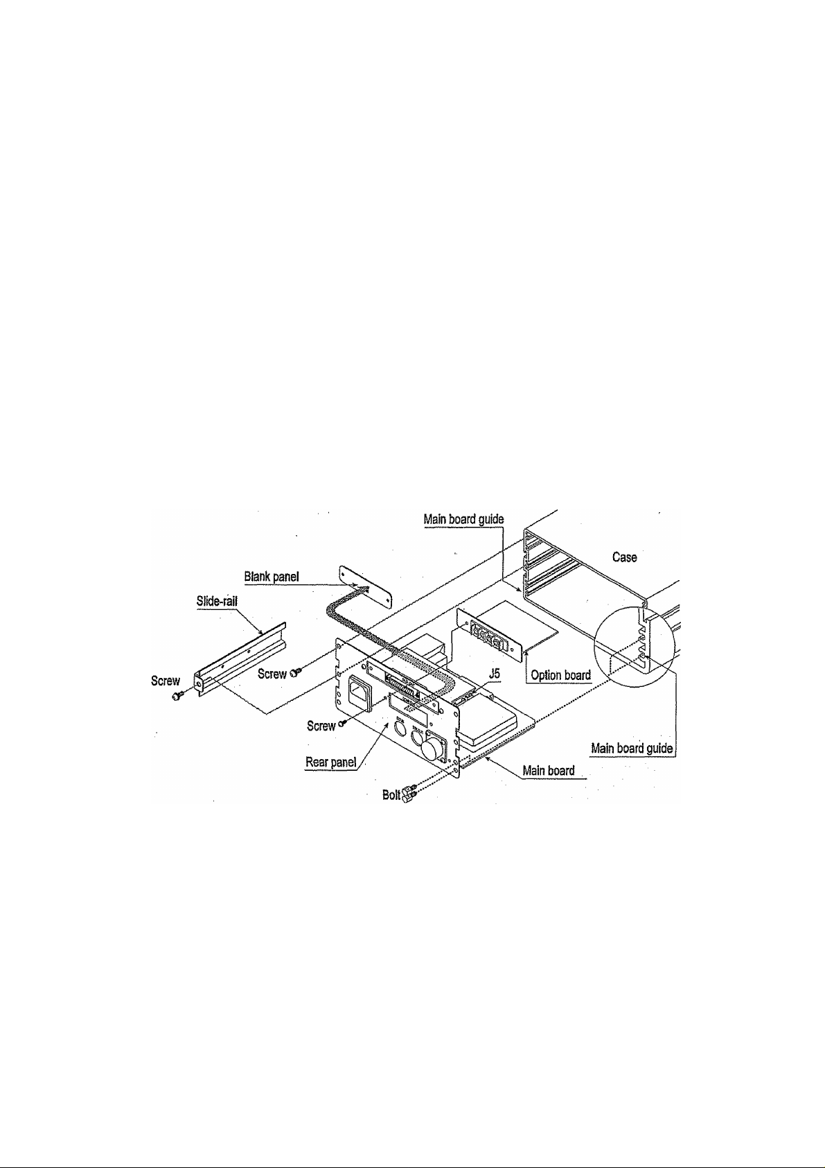
3,1,5, Installing the Option Board
Caution □ Do not remove screws without the following steps.
This is a procedure for the relay output board (OP-02).
Step 1 Remove the power cord and other cables from the indicator.
Step 2
Step 3
Step 4
Remove four screws and four boits from the rear panel.
Remove two slide-rails, one on each sides.
Pull the rear panel and main board from the case. Then the connector between the
main board and the display board may be disconnected smoothly.
Step 5
Step 6
Step 7
Step 8
Remove two screws and the small blank panel from the rear panel.
Attach the option board using two screws.
Connect the option cable connector to J5 on the main board.
Insert the main board into the both main board guides and insert it as before. Then the
connector between the main board and the display board Is re-connected, if the rear
panel will not close completely, retry step 8 to insert the main board correctly.
Step 9 Attach both slide-rails. Fix the rear panel using four screws and four bolts as before.
AD-4329 Weighing indicator
Page 7
3. Installation and Precaution
Page 10
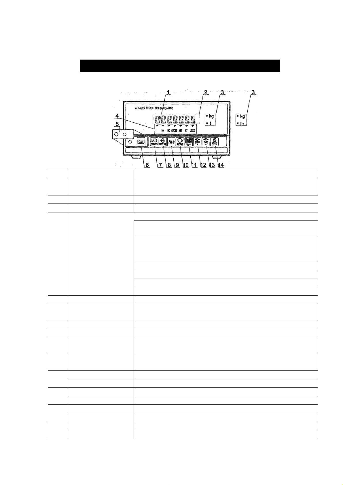
4.1.1. Front Panel Description
Panels and symbols
No.
1 Standby indicator
2
Data display
3 Weighing unit
State indicator
4
CAL cover
5
CAL key
6
7 Operate/Standby key
Preset tare key
8
9 M+ (Accumulation) key
10 Mode key
Net/Gross key
11
+/" key
Zero key
12
>key
Tare key
13
A key
Print key
14
Enter key, key
Name •
Description
The indicator lights at the standby state. This state means
connecting the power cord and turning the display off.
Weighing data Is displayed.
A unit selected in the CF functions.
The ^ marks indicate kind of data and weighing state.
M-f- It lights when there is accumuíation data.
it is blinking when displaying accumulation data.
MD The motion detection mark.
It lights when motion is detected.
It turns off while data is stabilized.
GROSS It lights when displaying gross data.
NET It lights when displaying net data.
PT It lights while entering a preset tare parameter.
ZERO it lights when displaying zero.
Calibration protection cover.
Calibration key. The key to adjust the scale so that mass
value is displayed correctly and to enter the CF functions.
The key to turn the display on or off.
The key to enter preset tare setting mode.
The key for the accumulation function.
Refer to "8. Accumulation", CF11, F4 and F5.
The key for the accumuiation function and calibration.
The key to select a unit of lb or kg.
The key to select net or gross.
The key to set the polarity of data while in the setting mode.
The key to zero a current display.
The key to select a figure while in the setting mode.
The key to perform tare.
The key to select a value while in the setting mode.
The key to output data.
The key to store current data while in the setting mode.
4. Description of Panels and symbols
Page 8
AD-4329 Weighing Indicator
Page 11
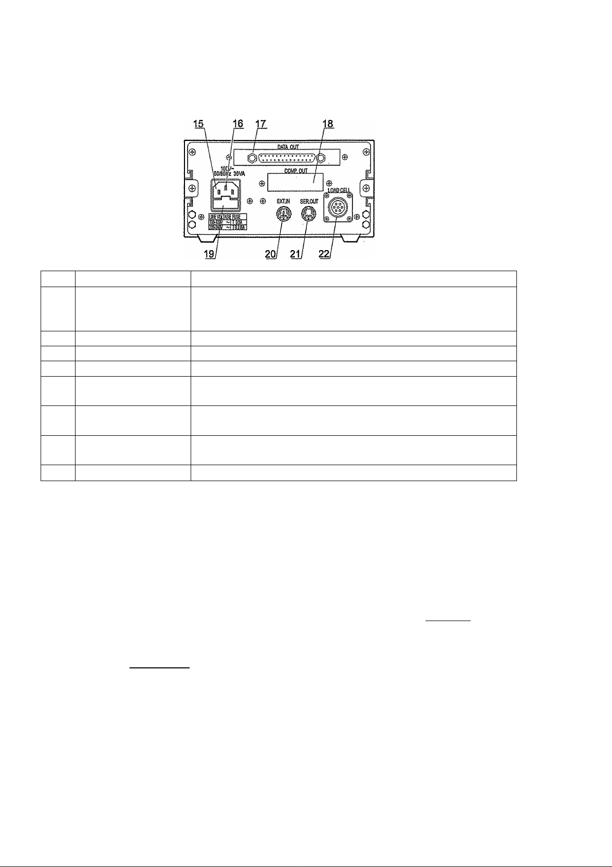
4.1.2. Rear Panel Description
No.
15 Power connector
16 Grounding terminal
17 RS-232C interface
18 Blank panel
19 Fuse holder
20 External input
21 Serial output
22
Load cell connector
Name Description
Use accessory power cord.
Please Confirm that the iocal voltage and receptacle type are
correct for your scale.
Refer to "12. RS-232C Interface" for the detail.
Option space (for relay output).
Use 0.5A time lag fuse for AC1OOV to AC120V.
Use 0.316A time lag fuse for AC200V to AC240V.
Seven control inputs selected function by the F functions.
Refer to FI 0 to 16.
Printer port. Refer to "11. Standard Serial Output" for the
details.
Connect accessory load cell plug.
4.1.3. Other Displays and Symbols
Blank
Decimai point
r r
AD-4329 Weighing Indicator
lг
standby display.
Zero error when turning display on. If the I mode I key is
pressed, a current weighing value may be displayed.
Over load display. Remove any load from the load cel!
immediately. It may cause damage to the indicator.
Example of an error display.
Page 9
4. Description of Panels and symbols
Page 12
4.1.4. Accessories and Option OP“02
1
1
(1)
1
1
JM-NJC-207-PF
JA-TCP0576
JA-TCP0586
FS-EAWK-500MA
Accessories
Instruction manual
Load cell piuq
Power cord
7pin Din connector
Spin Din connector
0.5A or 0.315A time lag fuse 1
FS-EAWK-315MA
Rubber foot 4
10-SJ-5023
Caution Please Confirm that the receptacle type and focal voltage is correct for
your indicator (scale).
Comparator relay output
Accessory
OP-02
Cable
AD4329-02
1
4. Description of Panels and symbols
Page 10
AD-4329 Weighing Indicator
Page 13

5. Calibration
This weighing Indicator, converts an input voltage from a load cel! to the "mass*' value,
and displays it. Calibration is the adjustment function so that the scale (indicator) can
weigh correctly.
5:1,1, items of Calibration Mode
There are seven items In the calibration function.
Basic Items
The minimum division.
The maximum capacity
Zero calibration
Span calibration
...
...................
..................
.........................
Comment This function Is the fundamental starting point to
..................... .
.....
_______________________
Setting the weighing interval.
Setting the maximum display.
When unloading any weight on the weighing unit
( there is nothing on the weighing pan), this function
performs adjustment so as to display the zero point
mark. Select an adjustment method from the.
"weighing input" or "digital input".
weigh anything, and influences the performance of
scale (indicator).
The function to measure an input voltage variation
by loading to the weighing unit correctly. Select an
adjustment method from the "weighing arbitrary
mass", "weighing capacity mass" or "digital input".
_____
Optional Items (Sub-functions)
Range function..........................
pigital linearization function
Gravity compensation function... The function to revise weighing error between the
Caution □ The maximum display is less than or equal to 10000 divisions. This number
is calculated from the maximum capacity divided by the minimum division.
□ Check the accuracy of weighing instrument periodically.
□ Recommended mass, use a mass heavier than 2/3 maximum capacity.
AD-4329 Weighing Indicator
...........
The function for a multi-interval scale. Select "dual
range scale" or "triple range scale". Each range has
parameters of "weighing range" and "division"
The function to revise a linearity deviation using
weighing points, (up to three weighing points)
calibration location and another weighing location
using gravity acceleration.
Page 11
5. Calibration
Page 14
□ Calibrate the scale, if It is moved to another location or the environment
'has changed.
□ It Is not necessary to set the gravity acceleration correction, when calibrating
the scale with a calibration mass at the place where the scale is used.
□ Enter the stable weighing data while the MD mark is turned off. If
unstable data Is used, it may cause a weighing error. Arrange the
condition using the FOO filter function.
□ The span calibration needs the zero calibration data. We recommend that
you perform the span calibration Immediately after the zero calibration.
□ Perform the digital linearization function immediately after the zero
calibration. And perform the span calibration continuously.
□ Select a decimal point and weighing unit at the CF function CFOO, CF 01.
□ If you use, the dual or triple range function of the multi-interval scale,
perform the “Range Function", “Zero Calibration" and "Span Calibration".
5.2. Calibration Procedure
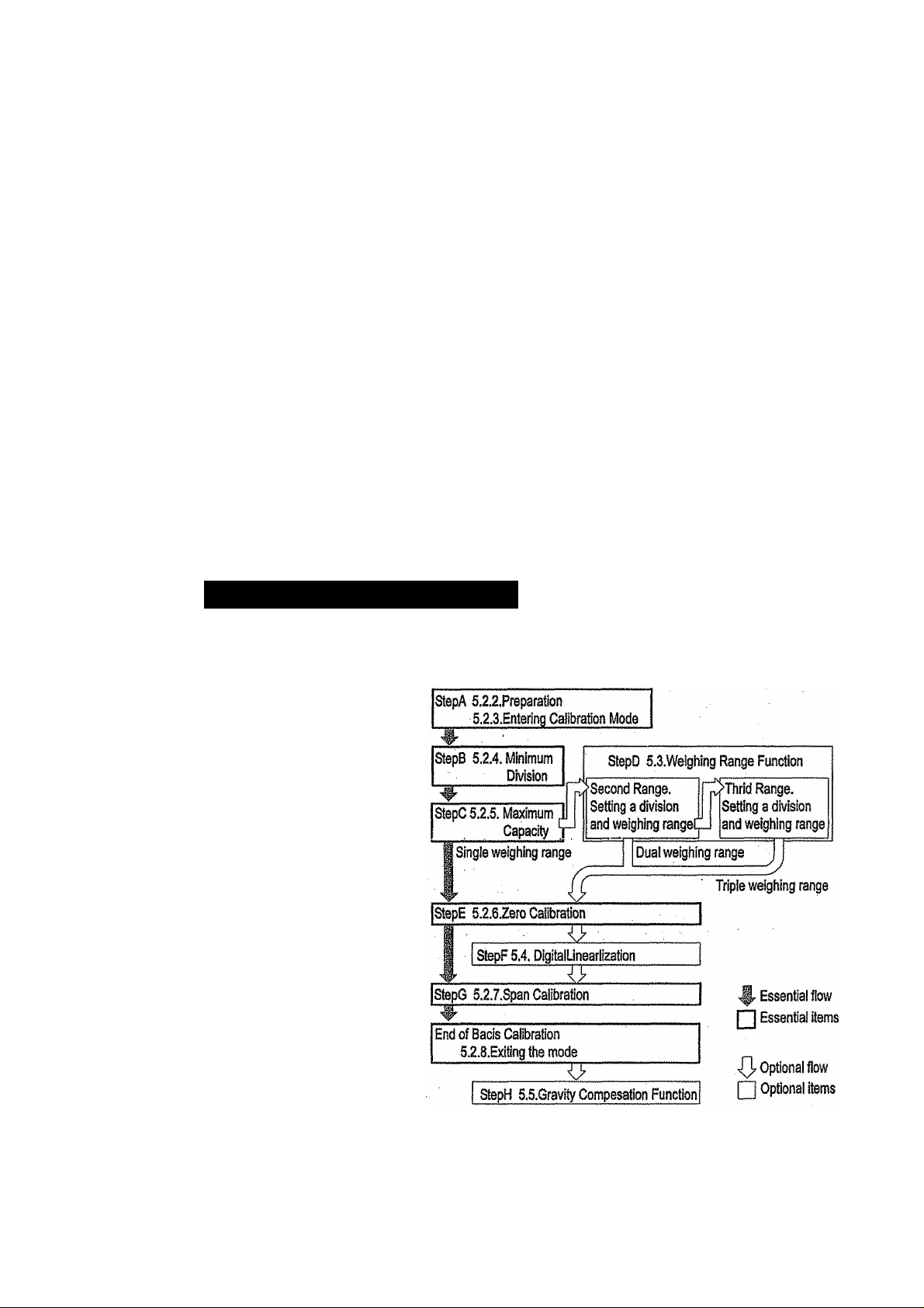
5.2.1. The Whole Procedure
Essential Items
Step A Preparation for calibration.
Step B Minimum division.
Step C Maximum capacity.
Step B Zero calibration.
Step G Span calibration
Optional Items
Step D Weighing range function,
i Perform this function just
before zero calibration and
span calibration.
Step F Digital linearization function.
Perform this function after the
zero calibration immediately.
And perform the span
calibration continuously.
Step H Gravity compensation function.
Perform this function after span calibration.
5. Calibration Page 12
AD-4329 Weighing Indicator
Page 15
5.2.2. Preparation
step 1 Keep the following conditions to calibrate the scale (indicator) correctly.
□ Maintain a constant temperature, stable power and stable input voltage from the
load ceil.
□ Avoid direct sunshine and in the neighborhood of an air conditioner.
□ Do not install the scale (indicator) where there is a strong magnetic field.
Step 2 Turn the display on during 10 minutes.
5.2.3. Entering the Calibration Mode
Step 3 Press the ICAlj key In the norma! weighing mode. The
two seconds when entering the calibration mode.
MODE! key.... Parameters are not revised and the next item is displayed.
CALI key........Parameters are stored in the indicator and Snd I is displayed.
Press the jOperate/Standbvl key to turn the display off.
Press and hold the ¡NET/GROSSl key and press the |CAU key
................
....All parameters are not changed
and the calibration mode is.
finished. Press the jOperate/Standby
key to turn the display off after
displaying CBnCEL
CHL (O
is displayed for
Turn the display on
for 10 miniuies
CAL
m ,n
AD-4329 Weighing Indicator
Page 13
Zero
Calibration^
Span Calibration.
^
5. Calibration
Page 16

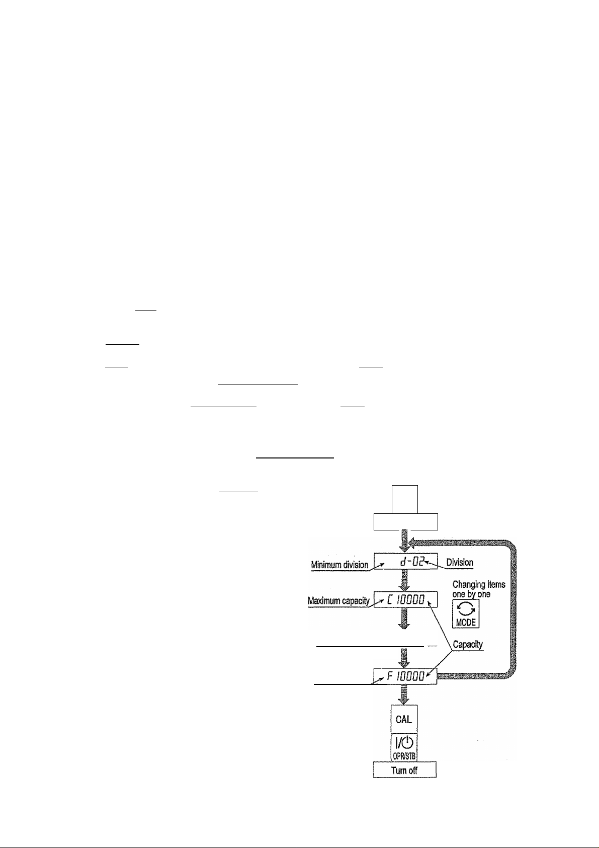
5.2.4. Minimum Division (Weighing Interval)
Step 4
Step 5
Check the | d-xx I display. The xx is minimum division (01,02, 05,10, 20,50).
Select a minimum division using the following keys,
A
key... The key to select a parameter,
key... The key to store a parameter and
proceed to step 6.
mode! key..The key not to change a parameter
and proceed to step 6.
M-H key ..... The key to proceed to "5.6. Gravity
Compensation Function".
To Gravity
Compesation Function
5.2.5. Maximum Capacity
Step 6 Check the [ ixxxx | display. The xxxx is current Maximum capacity
capacity. Select a new maximum capacity
using the foliowing keys.
>
key
.......... The key to select a figure.
A
key..
.........
The key to select a number.
key.......... The key to store a parameter
Minimum division
To Maximum Capacity
and proceed to step 7 (of the
zero calibration).
Imod^ key
PHESETTABg key,,
..........
The key not to change a
parameter and proceed to step 7 Punction
(of the zero calibration).
Weighing Range Function".
.....
The key to porceed to "5.3.
To Weighing Range
To Zero Calibration
5. Calibration
Page 14
AD-4329 Weighing Indicator
Page 17
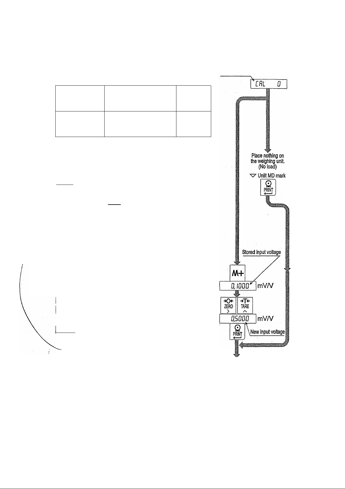
5.2.6. Zero Calibration
Step 7 Check the
Select a zero calibration method to adjust the zero point
Weighing input
(Normal way)
Digital input
Weighing Input
Step 8 Place nothing on the weighing unit. Press the key
after the MD mark has turned off. Proceed to steplO.
MOPg key
Caution Do not press the [ *-■ key while the MD mark is lit
(detecting motion). Arrange the condition using
the FOO filter function.
CfiL 0
.......
display.
The adjustment method
with nothing on the
weighing unit.
The numerical input to
enter a load cell output
voltage.
The key not to change the zero point
data and proceed to step 10.
To step 8
To step 9
Zero calibration
Digital Input
Step 9 Pressing the @ key, a stored input voltage parameter
of the zero point is displayed in the unit of mV/V. Adjust
the input voltage using the following keys.
key.....The key to select a figure,
key.....The key to select a number.
key.....The key to store the zero point parameter
and proceed to step 10.
MODE] key..The key not to change parameter and
proceed to step 10.
To Span Calibration
AD-4329 Weighing Indicator
Page 15
5. Calibration
Page 18

'Ш-
I
I
li
5.2.7. Span Calibration
Step10 Check the | Fxxxx I display. The xxxx is a capacity.
Select a span caliiDration method to adjust the capacity.
Weighing a mass except the
maximum capacity
Weighing maximum capacity
Digital input
The method to weigh a mass except
the maximum capacity.
The method to weigh a mass
equivalent to the maximum capacity.
The numerical input to enter a load
ceil output voltage.
To step 11
To step 14
To step 16
span calibration
Weighing a Mass except the Maximum Capacity
Step11 Set a mass value using the foilwing keys,
>
key
.....
Key to select a figure.
key Key to select a number.
Step12 Place a mass equivalent to displayed value on the
weighing unit.
Maximum capacity
StepIS Press the I ^ j key after the MD mark turns off.
Proceed to step 17.
MOPg key.
CAll key
Caution Do not press the
tit (detecting motion). Arrange the condition
using the FOQ filter function.
Weighing Capacity Mass
Step14 Place a mass equivalent to the maximum capacity on
weighing unit.
StepIS
Press the ] key after the MD mark turns off.
Proceed to step 17.
MODE! key
CALI key
.......
...........
......
..........
The key not to change parameter
and go back to step 4.
The key not to change parameter
and proceed to step 17.
J key white the MD mark Is
The key not to change parameter
and go back to step 4.
The key not to change parameter
Place the displayed
mass on the
weighing unit.
^ Unlit MD mark
Caution Do not press the
lit (detecting motion). Arrange the condition
using the FOO filter function.
5. Calibration
and proceed to step 17.
key while the MD mark is
Page 16
(To Next page, b) (To Next page, c)
AD-4329 Weighing indicator
Page 19

Digital Input
Siep16 Pressing the ^ key, a stored input voltage
parameter of the span is displayed in the unit
of mVA/. Adjust the input voltage using the
following keys.
>Tkey
.......
The key to select a figure. , "
A
' key
.....
The key to select a number.
key.....The key to store the span parameter
and proceed to step 17.
MQPEl key..The key not to change parameter and
go back to step 4.
CALj key
....
The key not to change parameter and
proceed to step 17.
5.2.8. Exiting the Calibration Mode
Step17 Check the j C8L End j display.
Use the following keys.
CALj key
......
Parameters are stored in the indicator
is displayed. Proceed toand End
step 18.
¡MOD^ key.. The key to memorize parameters
temporariiy. Proceed to the "Minimum
Division Selection".
Press and hold the iNEiyQROSSj key and press the ICAll key
All parameters are not changed,
CFInCEL
is displayed and the
calibration mode is finished.
Stepi 8 Press the jOperate/Standbyl key to turn the display off.
Í End
[8
CAL
End
1/0
OPRSIB
Turn display off
AD-4329 Weighing Indicator
Page 17
5. Calibration
Page 20

5.3. Weighing Range Function
The weighing range function can select "single range", "dual range” and "triple range".
Specify each weighing interval (division) for the multi-interval instrument Each
........
weighing interval is displayed according to a net value or gross value.
Caution a Using a single range, It 1^ not necessary to perform this function.
□ Perform the zero and span calibration after this function.
Example 1 The gross display.
Specified parameters:
First range
Second range
Third range
Range = 20.00kg, division 0.01 kg
Range = 50.00kg, division 0.02kg
Range - 100.00kg (maximum capacity), division 0.1kg
Display
0kg to 20kg:
20kg to 50kg:
60kg to 100kg:
Division
0.01kg
■lili
0kg
TiirinTiniTi
20kg
Division
0,02kg
The first range, division 0.01 kg.
The second range, division 0.02kg,
The third range, division 0.1 kg.
Division
0.1kg
I 1 1 It
50kg
Example 2 The net display using a 40kg tare value.
Specified parameters:
The same parameters as example 1.
Display
-40kg to -20kg :
"20kg to 20kg :
20kg to 50kg :
50kg to 60kg :
The second range, division 0.02kg.
The first range, divisiion 0.01 kg.
The second range, division 0,02kg.
The third range, division 0.1 kg.
Weiging value
100kg Gross
Division
0.02kg
nrminif
-40kg
0kg
5.3. Weighing Range Function
lilillitlllilill
-20kg 0kg
30kg
Tare vaiue
Division
0.01kg
1 I1Ì11
40kg
Division
0.02kg
iiiinrríTiTm
20kg
60kg
Page 18
Division
0.1kg
1
50kg 60kg Net
100kg Gross
Weighing value
AD-4329 Weighing indicator
Page 21

5.3.1, Setting Division and Range
Consider the foilowing rules to design the weighing range.
Rule 1 Select the division and range of each weighing range so as to fit the following inequality.
The first range < the second range < the third range
The division of next weighing range is automaticaliy set bigger than division of
lower weighing range. And the division can change.
Rule 2 When setting the dual range, the upper limit value of the second range becomes
the maximum capacity.
When setting the triple weighing range, the upper limit value of the third range
becomes the maximum capacity.
Rules Select a resolution smaller than 10000. The resolution is a value divided the
maximum capacity by the minimum division of the first range.
Mark to indicate the weighing range while this setting
w' mark
Net
Gross OFF
First range Second range Third range
ON
Procedure
Step 1 Press the |CAL| key to enter the calibration mode.
in
Then
CHL
is displayed for two seconds.
item Is displayed.
CAM key
.......
Parameters are stored in the indicator and
End
is displayed. Press the
key to turn the display off.
Press and hold the IneitgrossI key and press the |CAl| key
All parameters are not changed and the
calibration mode is finished. Press the
Qperate/Standbvl key to turn the display off after
displaying I EdnEEl
Normal weighing mode
CAL
in
[f!L
(
To Next page. A)
AD'4329 Weighing indicator
Page 19
5.3. Weighing Range Function
Page 22

Setting First Weighing Range
Step 2 Select the minimum division of the first range when
displaying I d~xx I. The xx is division.
CFrom last page./0
Minimum division
Step 3
I A 1 key..
MOPfl key
Specify the range of the first range.
>
A] key
PBESEFTAiti key,...The key to store the first range and
r ^ ] key
MOPd key......The key not to change the parameter
.......
The key to select the division.
key
......
.The key to store the new division and
proceed to step 3.
......
The key not to change division and
proceed to step 3.
key.......The key to select a figure.
.........
.The key to select a number.
proceed to step4.
..........
The key to store the value as the
maximum capacity for the single
range and proceed to step 10.v
and proceed to step i 0.
First range
•♦0^
ZERO
> !l ^
Í ID0Ü
Single range
CTo next page, b)
II •♦T*-
TARE
Setting Second Range
Step 4 The -w mark is displayed at net. Select a way.
Case 1
Case 2 if changing the second division, press the I A key
Step 5 Specify the range of the second range.
If keeping the current second division, wait for
displaying
xxxx is the range.
while displaying | CfíPc*-xx
A
key
key
Imop^ key.
>
key.......The key to select a figure.
A
key
Txxxx
........
The key to select the division.
.......
The key to store the new division and
proceed to step 5.
.......
The key not to change the division and
proceed to step 5.
.......
.The key to select a number.
and proceed to steps. The
. The XX is division. 2secc
nds
fi 15^
0 IV Second range
PRINT
Í IÚ00Ü
-»T*“
ZERO
>
riooF
( To next page, C )
TARE
new range
5,3. Weighing Range Function
Page 20
AD-4329 Weighing indicator
Page 23

Step 6
Case1
Specify the weighing range.
MOD^ key
PREilTAREl key,...The key to store the second range
Setting Third Range
Step 7 The ^ mark Is displayed at net and gross.
Select a way.
If keeping the current third division, wait for
displaying
The xxxx is the range.
Case 2 if changing the third division, press the lA i key
A
......
The key to use a single weighing
range and proceed to step 10.
I key
........
The key to store a value as dual
range and proceed to step 10.
and proceed to step 7.
ixxxx and proceed to step 8.
while displaying I TOT-xxl. The xx is division.
key
........
The key to select the division.
key
.......
The key to store the new division
(From ia$tpaae.C)
Single range
Duai range
and proceed to steps.
MOPg key......The key not to change the division
and proceed to steps.
Step 8
Specify the range of the third range.
I > I key
Step 9 Specify the weighing range.
key
key
........
The key to select a figure,
......
.The key to select a number.
key
....
.The key to use dual weighing
range and proceed to step10.
.......
The key to store the value as
triple range and proceed to
steplO.
( From last page, B)
SteplO ICBL B\ is displayed. Perform zero calibration
and span calibration from step7 at page 15 .
AD-4329 Weighing Indicator
Page 21
To zero calibration
and span calibration
5.3. Weighing Range Function
Page 24

5.4. Digital Linearization Function
Even if the zero and span calibration have been completed, there may still remain some
linearity deviation by the performance of the weighing unit The digital linearization
function can rectify and reduce the linearity deviation using weighing points during the
zero and capacity setting. Up to three weighing points can be specified.
Caution □ This function does not improve repeatability and hysteresis.
□ Use the mass on the condition that inr I < Lnr E < Lnr 3,
□ Do not press the I key while the MD mark is lit
Middle point
First Point
Second Point
Third Point
Step 1
Step 2 Press the SsETTAR^ key to enter this digital
Step 3 The value of the middle point is displayed after
Step 4
Zero calibration has been finished and Fxxxx
displayed. (Start this procedure from step 10 of
"5.2.7.Span Calibration")
linearization function.
indicating I tnr x j. x Is l,3 or3.
Select a way.
□
Press the iMODEj key to finish this function. Proceed
to step 7 and other points are cleared (canceled).
Q
Select a middle point value using the following keys.
Proceed to step 5.
5]
A I key
.........
............
Rash indication
Lnr 1
Lnr 3
i nr 3
The key to select a figure.
The key to select a number.
Net
Gross
Net and Gross
w mark
ts
ConHnue after zero calibration.
Span calibration
at step 10.
2 seconds
•>o<*
mo
>
L ¿500
f lOOOO
jr 1
L
TARE
A
Place the mass
"vZUnlit MD mark
Q
PRIfff
2 seconds
Inr p
*>Tv
ZERO
TARE
>
Second point i SQOO
Place the mass
v^Unlit MD mark
Q
PRINT
Step 5 Place a mass equivalent to the displaying value on
the weighing unit. Press the j ^ I key after the MD
mark has turned off. Proceed to step 6.
Step 6 If you add new middle point, proceed step 3, 4, 5.
If you finish this function, proceed to step 7.
Step 7 Perform step 10 of "5.2.7.Span Calibration" on page
16 immediately.
5.4. Digital Lineariz^on Function
Page 22
2 seconds
-K>
ZERO
>
Third point
L 1500
Place the mass
0.
MODE
Return to span catibraion
AD-4329 Weighing Indicator
Li
TARE
Q
yiNT
Page 25

5.5. Gravity Compensation Function
□ If the scale is used at the caiibraiion location, it is not necessary to perform this function.
□ it may cause a weighing error, if there is a difference of gravity acceleration
between the installed location and calibration location. This function specifies
these gravity accelerations and corrects span error.
Caution □ The decimal point is not displayed in the function. Ex, 313B = 9.798 m/s^
Step 1 Press the ICALl key in normal weighing mode. The Normai weighing mode
I C3L in is displayed for two seconds. Press the 1M+
key to enter the gravity compensation function.
If you want to cancel the current procedure, press
and hold the |NEi/GR0SS| key and press the |CAL| key. Then,
all parameters are not changed and the calibration
mode is finished. Press the lOperate/Standb^ key to turn the
2 seconds
CAL
[Ri in
d”0P
display off after displaying CRnCEL
Step 2 The parameter
gravity acceleration of the calibration location. The
parameter xxxx is the gravity acceleration.
>
key
..........
A
key
...........
key
..........
mode! key
Step 3 The parameter OB xxxx is displayed. Enter the
gravity acceleration of the installed location. The
parameter xxxx Is the gravity acceleration.
>n key
7T| key
mode! key
............
............
key...
.........
.........
........
01 xxxx is displayed. Enter the
The key to select a figure.
The key to select a number.
The key to store the new gravity
acceleration and proceed to step 3.
The key not to change the value and
proceed to step 3.
The key to select a figure.
The key to select a number.
The key to store the new gravity
acceleration and proceed to step 4.
The key not to change the value and
o
ZERO
Calibrated location
ZERO
Installed location
M4*
6 I 3000
-V|V
TARE
A
>
0 t 3138
Q
PRINT
08 3000
TARE
A
>
08 3800
Q
PRINT
1 3198
0
CAL
End
proceed to step 4.
Step 4 Now [ ¿W xxxx I is displayed. Press the ICAl] key to
store the parameters. The I End I is displayed.
Proceed to steps.
Step 5 Press the loperate/Siandby key to turn display off.
AD-4329 Weighing Indicator Page 23
I/O
0PR/ST8
Turn display off
5.5. Gravity CompensaBon Function
Page 26

M, -i: ,^sгl!.UiViíÄa;i ■líJi^luV5^
5-5.1 ■ The Gravity Acceleration Table
Amsterdam
Athens
Auckland NZ
Bangkok
Birmingham
Brussels
Buenos Aires
Calcutta
Chicago
Copenhagen
Cyprus
Djakarta
Frankfurt
Glasgow
Havana
Helsinki
Kuwait
Lisbon
London (Greenwich)
Los Angeles
Madrid
9.813 m/s^
9.800 m/s"
9.799
m/s^
9.783 m/s^
9,813
9.811
9.797
9.788
m/s^
m/s^
m/s^
m/s^
9.803 m/s"
9.815
9.797
9.781
9.810
9.816
m/s^
m/s^
m/s"
m/s®
m/s®
9.788 m/s®
9.819
9.793
9.801
9.812
9.796
9.800
m/s®
m/s®
m/s®
m/s® Washington DC
m/s®
m/s®
Manila
Melbourne
Mexico City
Milan
New York
Oslo
Ottawa
Paris
Rio de Janeiro
Rome
San Francisco
Singapore
Stockholm
Sydney
Tainan
Taipei
Tokyo
Vancouver, BC
Wellington NZ
Zurich
9.784
9.800
9.779
9.806
9.802
m/s®
m/s®
m/s®
m/s®
m/s®
9.819 m/s®
9.806 m/s®
9.809 m/s®
9.788 m/s"
9,803 m/s®
9.800 m/s®
9.781 m/s®
9.818 m/s®
9.797
m/s®
9.788 m/s®
9.790
9,798
9.809
9.801
9,803
m/s®
m/s®
m/s"
m/s®
m/s®
9.807 m/s®
[m/s2]
ALTITUDE
Sea Level
300m
600m
900m
1200m
1500m
1800m
2100m
0“ 10^ 20*^ 30“ 40“ 50'
5.5. Gravity Compensation Function
LATITUDE
Page 24
AD-4329 Weighing indicator
Page 27

5.6. Calibration Error Code List
Exiting from the calibration error
MODE] key ..The key to return the point occurred an error. Retry the operation.
Press and hold the ¡NET/GROSSj key and press the iCALj key
Al! parameters are not changed, the
calibration mode is finished.
Error Code List
if an error has occurred during calibration mode, the following code is displayed.
Error code Description
y ftîürU Atoji-ySVîàü^ a^^l'hiA »¿Yn'îîTîÇj XÎ'v.'-i.O' ïliïs^'tsSi > lï
CHnfEL is displayed and the
frr 0
Err 1
Err S
Err 3
Err H
Err 5
Err E
Err 1
Err B
Err 9
Err IB
Err 13
Ü Err
In multi-interval scale. The last division is set to maximum ( d-SO ).
Therefore the next division can not be entered.
Resolution exceeds 10000. (Resolution = maximum capacity/ minimum division)
Reduce maximum capacity or increase minimum division.
Load cel! output is, too iarge or too small at zero calibration. Check the weighing
unit and load cell. Refer to "3.1.4.Verifying Load Cel! Output and Input
Sensitivity".
Measuring calibration mass (or entering digital input), the value exceeded
maximum capacity. Reduce calibration mass (or digital input).
Selected calibration mass Is smaller than minimum division.
New input sensitivity is less than 0.2 //V/division. Increase input sensitivity.
Refer to "3.1.4.Verifying Load Cell Output and Input Sensitivity".
Placing mass on the weighing unit, the load cell output becomes a negative
value. Check the load cell cable connections and the direction of load cell
mounting.
Load cel! output exceeds the input range before maximum capacity.
Adjust zero balance referring to "3.1.4.Verifying Load Cel! Output and Input
Sensitivity", Replace with a load cell designed smaller output. Reduce maximum
capacity.
The weighed value is out of the input range at zero calibration or span
calibration. Check the weighing unit and cables.
The last weighing range is larger than next weighing range.
Incorrect mass is selected at the digital linearization function.
Select mass of the following relation. L nr l<inr B<Lnr 3.
An unacceptable value was selected in the gravity acceleration function.
Exit this error using the Operate/Standby key.
AD-4329 Weighing indicator
Page 25
5.6. C^ibration Error Code List
Page 28

6. Functions
There are two parameters list for the F-functions and CF-functions, These functions
control the indicator. The parameters of each function are stored in the EEPROM, and
are not lost even if the AC power supply is disconnected.
F-functions: These parameters can always be changed and are used for
internal settings.
CF-functions: if you accept a certificated approval of the weighing instruments,
the CAL cover must be sealed. Therfore, accepting this approval,
these parameters of the CF-function can not be changed.
6.1. Changing the Function Settings
Step 1
Step 2
Operating Item
Step 3 Select an item using the following keys,
Operating parameter
Step 4 Select a parameter using the following keys.
Press the ppeiateifStandbvi key to turn the display off.
Press and hold the iMOPg key and press the
Operate/Standbvi key. The I F~Q0 I is displayed.
key..... The key to select a figure.
A
key
.....
The key to select a number.
key..... The key to display a parameter of
the selected item.
Proceed to step 4.
CALI key
> ! key..
......
The key to exchange F-functions
and CF-functions.
.. The key to select a figure or a switch |
(atP-05 andP-%). i
A 1 key..
..The key to select a value (or condition |
atP-Ofi).
'm
OPRISTB
Display off
Press and hold
Press
F-Fuhci!ofis
P-00
ZERO
>
Q
PRINT
•KX
ZERO
>
F-0
Q
PRINT
O'
MOD
Vpf-
TARH
y\
-♦TA
TARE
1 8^
I/Ò
CF-Functions
CAL
CP-00
I The same ,
i operation as ■
I F-Functions
Parameter
key..... The key to store a parameter and proceed
to step 3. (all switch stored at P~06)
MODE! key ..The key not to change the parameter. Proceed to step 3.
Step 5 Press the pperate/Standbyl key to exit the mode. Then display turns off.
6. Functions
Page 26
.mvsiB
Display off
AD-4329 Weighing Indicator
r
Page 29

6.2. F-Functions
Digital Filter
Item
Filter
Motion / Averaging
time
F-Ol
Zero tracking
F-D?
MD mark
Motion .detection
condition
Parameter
n
u
i
3 16 d/1.6s
H. 32 d/1.6s
s
6 128 d/1.6s
7 2 d/ 3.2s
*8
S 8 d/3.2s
. 10 16 d/3.2s
II 32 d/ 3.2s
18 64 d/3.2s
13 128 d/3.2s
0 OFF
t
1
8
3 1.5 d/Is
H 2.0 d/ls
S' .
6 0.5 d/ 2s
7
*8
3 2.0 d/2s
10 2.5 d/2s
0 No motion detection
1
1
8
3 2.0 d/0.5s
3
5 4.0 d/0.5s
6 0.5 d/ls
7
*8
9 3.0 d/ls
10 4.0 d/ls
0.5 d/ls
1.0 d/ls
2.5 d/1s
1.0 d/2s
1.5d/2s
0.5 d/0.5s
1.0 d/0.5s
3.0 d/0.5s
1.0 d/ls
2.0 d/ls
2d/1.6s
4 d/1.6s ,
8 d/1.6s
64 d/1.6s
4 d/3.2s
Description
If weak filter is set, the
response wiii be fast, but will be
more sensitive to external
influences such as vibration.
This function traces the .
weighing value drifting around
zero point slowly, displayed as
zero. If a strong parameter is
set, a very small zero drift may
be not detected,
if if "88 is 1, the 8, l,S or 7
can be selected only.
If if-88 is 1, the initial setting
sets 7.
The function to set the
condition of Judgment whether
a weighing value is unstable or
«îtablp Thp ZERO kpv and
1 1 iV^ IV/ l\V^y VII IV4
1 MfiC i\uy I Ido in U №
stable state. If these keys need
in the unstable state, set to f~
88 8. In case of lF"88 l,F~08
8 or F "88 7 can be selected
only. (Internal setting is 6.)
d: division (weighing inten^al) of first range,
s: second.
*: factory settings (Initial settings).
AD-4329 Weighing Indicator Page 27
6. Functions
Page 30

Display
Item
f-03
Display update rate
Accumulation Mode
F-OS
Inhibit region for
accumulation
F-OS
Disabling keys
Parameter
10 tirnes/s
6 times/s
0
Manual _ + only
Manual + /
Automatic + only
Automatic + / -
0
Add data anytime
Above ±5 d
Above ±10 d
Above ±20 d
Above ±50 d
*0
/
I
ON/OFF key
P
Preset tare key
3
M+ key
3
Mode key
5
Net/Gross key
S
Zero key
7
tare key
8
Print key
enable
disable
A i key
key
Description
The selection in the unstable
condition.
The selection for the way of
adding data and kind of data.
The selection of the inhibit
region for accumulation
A key is selected by the left
parameter
A key condition is selected by
the right parameter:
When specifying 1 at the right
parameter, this key does not
work.
Use the function to avoid misoperation of 8 keys on the front
panel without | GAL | key.
External Input
Item
F-/0
EXT1 ,
Function selection of
external input
f - //
EXT2
F-!3
EXT3
6. Functions
Parameter
*0
3
3
H
B
8
3
IQ
11
The same as F"/0
The same as f-/0
Not used (No function)
I
Zero key
Tare key
Print key, f^key
Operate/Standby key
5
M+ key
Net/Gross key
1
Mode key
Gross display when shorting terminal.
Accumulation data display when shorting terminal.
Over signal. Gross over and display data are output.
All keys are enable when shorting terminal.
Page 28
Description
AD-4329 Weighing indicator
Page 31

F- !3
EXT4
f - /V
EXT5
f-15
EXT6
F- ¡6
EXT7
division (v\^e!ghing interval) o1 first range,
factory settings (Initial settings),
second.
Comparator
Item Parameier
F-iO
Comparator function
F-c’l
Comparator mode.
Condition to compare
data.
The same as/u
The same as F - /и
The same as F-/0
The same as F- !0
*0
Not used
1
Upper/lower limit comparison. Set F-P1, too.
г Setpoint comparison
*0
All data, always
i
Stable data
p
Data exceeding +5d
3 Stable data exceeding +5d
Ч Data exceeding -5d to -fSd
5 Stable data exceeding -5d to -fSd
Description
WhenF-гíJis /,
F-c* / is effective.
Standard Serial Output
Item
C_ 30
r Du
Output Data
F~3f
Output mode
F-3P '
Auto-print condition
F-33
Delay for continual data
f^jLj
Baud rate
bps: bit per second.
d: division (weighing interval) of first range.
*: factory settings (Initial settings).
AD-4329 Weighing Indicator Page 29
ParaiTieter
*0
Lj
*0
*0
1
1 Positive and negative data
*0
Displayed data
1
Gross data
P Net data
3
Tare value
Gross data / Net data / Tare value
Stream mode
1
Auto print mode
P Manual print mode
Positive data only
Not used In case of F-3 / 0, the
I Approximately 2 seconds
0
1
*p
600 bps
1200 bps
2400 bps
Description
F-53 is ineffective.
6. Functions
Page 32

RS-232C Interface
Item
f-HO
Output Data
F-HI
Output mode
F~нг
Auto-print condition
F"V
3
Delay for continual data
F-HH
Baud rate
F-HS
Data format
F-%
Address
Parameter
*0
*0
*0
Ü
Displayed data
Ì
Gross data
Net data
Tare value
3
Gross data / Net data / Tare value
3
Stream mode
i
f Auto print mode
Manual print mode
Command mode (no address)
3
V
Command rriode with address
Positive data only
Positive and negative data
;
Not used
1
Approximately 2 seconds
600 bps
Î 1200bps
*г
H 9600bps
*0 Format 1
2400bps
3 4800bps
1 Format 2
00 to
S3
Factory setting is 00
When F~S !
.
4
is not selected,
Description
In case of F-4 / 0, the
F“ 43 is ineffective.
Referto "12.1.2.Data Format”
F-%
is ineffective.
bps: bit per second.
*: factory settings (initia! settings).
6. Functions
Page 30
AD-4329 Weighing Indicator
Page 33

Description of “Stream Mode"
Object
Operation
f-3l 0 J-HI 0
Data is output in every sampling (when refreshing the display).
Use this mode to output data to an external display (Data may not be output
due to timing of the baud rate and interna! sampling rate), if data is printed
with pressing the IPRINTI key on the printer, use the stream mode.
Description of “Auto Print Mode”
Object F~3 1 I , / I
Operation When weighing data varies from the "inhibition region of output" to the
"permission region of output", the stable data is just output once. If you use
this mode, setexcept 0.
□
□
When weighing (and removing) each object and printing the data, use this
mode.
in case of F~33 O or, F~33 0
"Inhibition region of output" ^ +5d.
+5d < "permission region of output".
□ In case of /1 or, f
“5d "inhibition region of output" ^ +5d.
"Permission region of output" < -5d, +5d < "permission region of output".
d: division (weighing interval) of first range.
Description of "Manual Print“
Object F-3 / 3 , F~3 I 3
Operation When pressing the [PRINTi key, the stable weighing data is just output once
Description of "Delay for continual data"
Object f-33,f~H3
Operation This function can be used in the "Auto print mode" and "Manual print mode"
When using a non-buffered printer like the AD-8121, set to F-33 I and
P-VJ / .
AD-4329 Weighing indicator
Rage 31
6. Functions
Page 34

6.3. CF-Functions
I.U Ivu jwiiVÌHa. Ill
Item
rp-PP
ir uu
Decimal point position
[F-Oi
Weighing unit
iP-OP
Zero range
Turning display on, the .
range to zero display.
CF-OB
Zero track width, motion
detection condition
[F-OH
Zero tracking
CF-05
Power-on zero
[F-OS.
To inhibit preset tare
ff-07
Data output of tare
[F~08
Output on over load and
unstable state.
[F~0B
Header 2
Parameter
0
None
First fipure
Second figure Example: 123.45
Third figure Example: 12.345
kg.
lb
Ib/kg alternately
±2% of CAP, Tare limit is 100 % CAP
±10% of CAP. Tare limit is 100% CAP
±3% of CAP, Tare limit is 50 % CAP
±4% of CAP. Tare limit is 50 % CAP
iJ
No limitation
Use limitation at/^-0 / 0, I, B, 1 and F~0B 6, 7 only.
0 Gross when displaying gross.
Gross
Gross or Net when displaying net
Not to zero when turning display on.
To zero when turning display on.
0
To permit preset tare.
To inhibit preset tare, (ineffective preset tare key)
0
According to F~3D, F~H0.
Using preset tare value and output net, a tare value is
output on manual mode or auto print mode (In CF-03 E,
a tare value is output at all mode except command).
Not to output data at unstable value or over load.
0
It IS effective in key mode.
To output data always.
0
*0
Gross
GS
GS
1
Guj
E
Net
NT TR
NT TR
N^
Description
Example: 12345
Example: 1234.5
____________
Tare
T^
Preset tare
PT
PT
PT
[F- 10
Figure number of unit
for format 1 and
decimal point
[F-lf
Accumulation function
CAP : maximum capacity
6. Functions
0
Two figures . (dot)
Three figures , (dot)
Two figures , (comma)
Three figures , (comma)
0
Not used (ineffective)
Use (Effective)
Page 32
Format 1 on standard
serial data output and
RS-232C interface.
Decimal point is effective
at format 1 and 2.
AD-4329 Weighing indicator
Page 35

Tare
a The function is used to display a net value with the container weight subtracted from
the total weight, if you put an object into a container to weigh it.
o There are two methods for the "weighing tare weight" and "digital input of tare weight".
□ Using the RS-232C Interface, you can perform digital input from external equipment.
Caution □ When turning the display off with if -05 I, the tare value is cleared.
□ When turning the power off, the tare value is cleared.
7.1.1. Weighing Tare
Operation Put the tare on the weighing unit. Press the [TAREl key to store the tare weight
after the MD mark turns off. The dispaly changes to net.
Caution o When displaying a negative gross value, tare can not be used.
7.1.2. Digital Input
Caution □ The input value Is rounded off to the unit of division (weighing interval).
□ In case of rr-05 l(power-onzero), the display value will be zeroed when
turning the display on.
□ When using a multi-interval scale, usable input range is the first range.
Q In case of if-05 /(To inhibit preset tare), preset tare can not be used.
Step 1 Press the [PRESET TARg key to display the stored tare value.
When tare is cleared or is not used, the value is zero.
Step 2 Enter a new tare value using the following keys.
S
................ The key to select a figure.
7n key
.............
key
..........
The key to select a number,
The key to store a new tare vaiue.
The net is displayed.
7.1.3, Clearing Tare
□ When pressing the [TAREj key while gross is zero, tare is cleared and gross Is
displayed.
□ When zeroing with the IZEROl key, tare is cleared.
AD-4329 Weighing Indicator Page 33
7, Tare
Page 36

8. Accumulation
The function accumulates weighing data and stores sum of weight and count of
weighing. Data is stored in the EEPRQM, and is not lost even if the AC power
supply is disconnected.
8.1.1. Preparation and Specification
Set the following parameters to use the accumulation function.
□ Select [F - I I / for the CF-function so that the accumulation function becomes effective.
□ Specify the method of accumulation and data at F -04 of the F-f unction.
□ Specify the Inhibit range for accumulation at F-05 of the F-function.
Selection of Accumulation Mode, F-OH of the F-function
□ There are two methods of manual accumulation, with the
automatic accumulation.
□ The accumulation data can select “positive data only" or "both polarity data".
Accurhulation Mode F-OH Data to accumulate
Manual accumulation mode
Automatic accumulation mode
F-OH 0
F~iJH 1
F'OH г Positive data only
F-DH 3
Positive data only
Both polarity data
Both polarity data
key operation and
Accumulation Condition, f-05 of the F-function
□ in case of manual accumulation mode, press the @ key to accumulate weighing
data when the MD mark turned off.
□
Data can be accumulated after weighing value becomes to the "inhibition region of
output". When connecting power cord and truning display on, the accumulation mode
makes the same action.
Inhibition region for accumulation
Add data anytime F“05 0
Above ±5 d
Above ±10 d
Above ±20 d
Above ±50 d
Caution □ Do not set to f-05 0 for the automatic accumulation mode
□ If setting to F “05 0, it may add the same data two times or more.
Limitation of Accumulation Count and Total
□ The limitation of accumulation count is 999999.
The limitation of total is ±999999 ignoring the decimal point.
□ if exceeding these limitations, data is not accumulated.
Example: Setting the decimal point to second a figure like "0.0", the limitation is "99999.9".
F-G5
F"fl5 /
F“£J5 ?
F-05 3
F-05 4
Stable data can be used anytime
Factory setting
Description
r'
8. Accumuiatton
Page 34
AD-4329 Weighing Indicator
Page 37

8.1.2. Display and Operation
Action of Accumulating Data
□ When accumuiating data, the display blinks once.
If storing accumulation data, the M+ mark Is displayed.
Caution □ This function can not accumulate different unit data. Specify a unit before use.
Display of Accumulation Data
□ When setting to if - I / I (Effective accumulation function) and pressing the ¡MODE
key, the I totRL I is displayed and the total data is displayed with the M+ mark
blinking . If the ImopeI key is pressed again, the weighing data Is displayed.
The total data can be output. Refer to "Output of Accumulation Data"
if "Ib/kg" of [f-D I 3 Is selected, the display of "ib", "kg" and "total" is exchanged
with the IMOPEI key in order.
Undoing the Accumulation Data
□ The last weighing data can be deduced from the accumulation data unless new
data is accumulated.
Step 1
Step 2
Press the ¡MOPEj key to display hatRL
Press and hold the g key more than 3 seconds. The display blinks once and the
and accumulation data.
last accumulation data before accumlating last weighing data is displayed.
Caution □ External input can not be used.
Clearing the Accumulation Data
Step 1 Press the ImodeI key to display I totBl | and accumulation data.
Step 2 Press and hold the |ZERO| key more than 3 seconds. The display blinks once and
the accumuiation data is cleared.
Caution □ External input can not be used.
Output of Accumulation Data
□ Accumulation data can be output to the standard serial output and RS-232C
interface using the manual print mode.
Step 1 Press the |mode| key to display I frolrfff. I and accumulation data.
Step 2 Pressing the IPRIMH key, the count and total of accumulation data are output in order.
\
Header
..............
4.
ojo
f
^
Data
0 0
0|0I
] ySpace(20h)Example: Count
Terminator
Total fTToiTiA|L|,kl0|0|0|0i0|0|likig|CR[h.|
Header
AD-4329 Weighing Indicator Page 35
Data
Unit Terminator
8. Accumuiation
Page 38

9. Comparison
□ This function has the "upper / lower comparison" and the "setpoint comparison". They
compare the weighing data with preset parameters and can output the result of the
comparison to the reiay-outputs of OP-02.
□ Set the F-function the/^*¿'0 and /to use these comparisons.
Caution □ The result can only be output using relay-outputs, and is not displayed.
□ The setpoint comparison can be used for normal batching, but can not
be used for loss-in-weight.
9.1. Comparator Output Relay (OP-02)
□ This relay option outputs the result of comparison controled by the F-function f~^0
(comparator function) and / (comparator mode).
Specifications
Maximum voltage
Maximum current
Contact life
Adaptable terminal type
Circuit and pin layout
250V AC or 30V DC
ЗА (resistive load)
100,000 times (resistive load)
М3
Relay
777
Inside of OP-02
6.2
3.2
6.2
12 3 4
HI OK LO Common
Adaptable Compression
Terminal
9.2. Upper/Lower Limit Comparison
This function compares the weighing data with the upper limit value and lower limit
value, and outputs the result to the three relays of HI, OK and LO. Use this comparison
when judging whether a weight is proper.
□
Set to the F-function f~EQ I to use this upper/ lower limit comparison.
□
Select a parameter of the F-function I for the comphson condition.
□
Specify the upper and lower limit values.
□
When inputting the upper value and lower limit value, it is not necessary to input the F-
function f ~ BQ and f 1 again unless changing the F-function,
3.2
9. Comparison
Page 36 AD-4329 Weighing indicator
Page 39

9.2.1, Selecting Upper/Lower Limit Comparison
step 1 Press the lOperate/Standbyl key to turn the display off.
Press and hold the iMOPEl key and press the
Operate/Standbvl key to enter the F-function mode.
Step 2 Select F~^0
(upper/lower limit comparison).
Step 3 Select comparison mode at F-^ I using the foilowing keys.
A ! key..
..The key to select a parameter.
..The key to store the parameter.
key..
Step 4 Turn the display off using the lOperaie/Standbyi key.
Reference
F "c’u 0
Not used
F-гo / Upper/lower limit comparison.
F-’c'u (? Setpoint comparison
F~PI Comparator mode
F-Pl 0
F~PI /
Ail data, Always
Stable data
F-Pt P Data exceeding +5d
F-p 1 J
F-Pl 4
F-гl 5
Stable data exceeding f5d
Data exceeding -5d to -fSd
Stable data exceeding -5d to +5d
F-Function mode
Comparator function
F-Vo ;
Upper/lower limit comparison
Comparator mode 1
-----------
----
______
F-ei p
Data exceeding -^50
Display off
9.2,2. Condition formula for Comparison
Comparison is performed based on the foilowing formula.
state Name
HI (Over)
OK (GO)
,,,,LO,,iynder)
Lower limit value ^ Display value ^ Upper limit value
__
Upper limit value < Display value
Display value < Lower limit value
□ The decimal point is not considered. Example: If the upper limit value is 10.0, input 100.
□ These parameters are stored in the EEPROM, and are not lost even if the AC
power is disconnected,
□ When the display value becomes an over load (positive over), HI (over) is outout.
When the display value becomes an under load (negative over), LO (under) is output.
□ The upper limit value and lower limit value can be set to a negative value.
□ This function compares the upper limit value first.
□ This function does not check the relation of upper limit value and lower limit value.
AD-4329 Weighing Indicator Page 37 9.2. Upper/Lower Limit Comparison
Condition Formula
Page 40

9,2,3. Setting Upper/Lower Limit Values
Step 1 Press the loperaie/Standbyl key to turn the display off.
Step 2
Press and hold the iPRINn key and press the
Qperate/Standbvl key to display J H j | for two seconds.
Step 3 Set the upper limit value (HI) using the following keys.
r> 1 key The key to select a figure.
A key
.........
The key to select a number.
+/-1 key
key
.....
The key to select plus or minus.
.....
The key to store the parameter and
proceed to step 4.
ImodI key ..The key not to change the parameter
and proceed to step 4.
S^6p 4 La is displayed for two seconds.
Set the lower limit value (LO) using the same keys as step 3.
Step 5 Turn the dsiplay off using the ^pemte/Standbvl key.'
2seconds
Upper limit value
2seconds I о
Lower limit value.
I/(!)
mm
Display ofl
Q
Press and hold
PRINT I-
1 / Ф
0PR/ST8
И
О
m/G
moss
Ш0
>
5000
Q
PRIfiT
Uei/B/G
ZERO
-f/*“
>
иш
Q
PRINT
OPRiSTB
Display ofi
Press
ТАЙН
A
TARE
A
9.2.4, Example
F-function:
Upper iinit value:
Lower Unit value:
Result
Condition Formula Range HI (Over)
5000 < Display value
1000 S Display value ^ 5000
5 < Display value < 1 GOO
Display value ^5
f-PO
F'Pl
5000
1000
5001
5000
1000
999
OK (GO)
ON
LO (Under)
OFF
ON
ON
6
5
OFF
9.2. Upper/Lower Limit Comparison
Page 38
AD-4329 Weighing Indicator
Page 41

9.3. Setpoint Comparison
□ This function includes the weighing sequence and uses for getting preset target
weight.
□ There are four parameters of "Final", "Preliminary", "Free fall" and "Zero band" to
use the setpoint comparison.
□ The result of the sequence is output to three relays.
□ When inputting these parameters, it is not necessary to input the F-function f-^0
again unless changing the F-function.
Caution □ This function is normal batching only and can not perform loss-in-
weight.
9.3.1. Selecting Setpoint Comparison
step 1 Press the lOperaTe/Standbyl key to turn display off.
Press and hold the [MOPEl key and press the
Operaie/Standbvi key to enter the F-function mode.
Step 2 Select f-c’O c’ (setpointcomparison).
Step 3 Turn the display off using the [Operate/Standbyl key.
9.3.2. Description of Input parameters and Outputs
Weighing value a
SETO, Final
SET2, Preliminary
Tared Zero
Caribrated Zero
Relay HI, Net ^ {Final - Free fall)
Relay OK, Net^ (Final - Preliminary)
Relay LO, Gross < Zero band
OFF (Break)
ON (Make) OFF (Break)
Preset target weight
OFF (Break) | ON (Make) OFF (Break)
Comparator function
Setpoirit comparison /
ON (Make)
F-FunctiorLmode
/
Display off
Weighing trace
OFF (Break)
ON (Make)
Parameters List
SETO Final
SETI Free fall Set a corrective value related to closing the dribble flow gate.
SET2 Preliminary
SETS
AD-4329 Weighing Indicator
Zero band
Set a preset target weight.
Set a begining point to use the dribble flow gate on!y.
Set a value to regard as neariy zero.
Page 39
9,3. Setpoint Comparison
Page 42

9.3.3, Setting the Parameters of Setpoint Comparison
step 1 Press the loperate/Standb^ key to turn the display off.
Step 2 Press and hold the IprintI key and press the
lOperate/Standbvl key to display .15^1: 0 for two seconds
Step 3 Set the "Final" using the following keys.
>] key.....The key to select a figure.
"7C| key
.....
The key to select a number.
I +/-1 key.....The key to select plus or minus,
key..... The key to store the parameter and
proceed to next step.
MOPEj key ..The key not to change the parameter
and proceed to next step.
Stsp 4 Sit: I is displayed for two seconds.
Set the "Free fall" using the same keys as steps.
5 SEt P is displayed for two seconds.
Set the "Preliminary" using the same keys as step3.
Display off
Q
pm .
2seconds Sft 0
Mel/ S/ G
iTiG PO SS
4*/—
Pinal
MBIG
new
Free fall
2seconds
Nsl/B/G
eiGRG SS
•4*/—
Prerimtnary
Press and hold
!/(!)
Press
OPR ÌST B
TARE
ZERO
>
soon
Q
PSiflT
Sit I
•K>
ZERO
TARE
ys
>
100
Q
PRlUr
SEt i I
•»TV
ZERO TARE
>
SÙQ
Q
PRiilT
Step 6 5Et 3 is displayed for two seconds.
Set the "Zero band" using the same keys as step3.
Step 7 Turn the display off using the jOpemte/Standb^ key.
2seconds SEt E
Zero band.
Display of!
ZERO
SO
0
PRiMT
l/C!)
OPR /ST Bi
TARE
9.3. Setpoint Comparison
Page 40
AD-4329 Weighing Indicator
Page 43

1 0. External Control Input
□ The connector "EXT.IN" can be used to control the indicator from an external terminal
like a front panel key operation,
□ Set the external control function at f - /0 - f - / 7 of the F-Functlon.
□ When shorting each function pin and common pin, the Indicator makes the action.
Caution □ Keep a signal width more than 100 ms for the On-time and Off-time.
Pin No.
1 pin
2 pin
3 pin
ON (Make)
OFF (Break)-I
F-Function
F~ IÜ
EXT1
f~ II
More than 100ms
PhotoCoupier Relay, Switch
Parameter Description
0
1
B
More than 100ms
<^r~AAA^
! U
2pin
Common pin
Not used (No function)
Zero key
Tare key
3 Print key, ^ key
Ij
Operate/Standby key
s
M+ key
5
Net/Gross key
7
Mode key
e Gross display when shorting terminal.
3
Accumulation data display when shorting terminal.
IÜ .
Over signal Gross over and display data are output.
II
All keys are enable when shorting terminal.
Common pin for EXT1 EXT7.
The same as F ~ 10
4J)C+5V
560Q
1,3,4,5,6,7,Spin
The inside of AD-4329
4 pin
5 pin
6 pin
7 pin
8 pin
Case
AD-4329 Weighing Indicator
F~lг
EXT3
r- ii
EXT4
f- N
EXT5
F"/5
EXT6
F" IB
EXT7
The same as F - /3
The same as F- 10
The same as F ~ 10
The same asF ~ ¡0
The same asF-10
Shield.
Page 41
10. Externat Control Input
Page 44

11 . Standard Serial Data Output (SER.OUT)
The standard serial data output can be used to output the data to an A&D printer and a
display unit.
Set the - SG ~ f -3^^ of the F-Functions to use this output.
When using a non-buffered printer like the AD-8117, AD-8117A and AD-8121 etc, the
printer can not receive data while printing. Therfore, set to Я -.35 / for the manual print
mode or auto print mode.
Related Functions
Output Data
F-Function
F~JÜÜ
f-30 1
f~ 3B г
F-3Ü3
F-3Ü Ч
Description
Displayed data
Gross data
Net data
Tare value
Gross data / Net data / Tare value
Pin No. Signal
Spin
5 pin
Other pins
Case
Current loop
Not used
Shield
Output mode
Stream mode
Auto print mode
Manual print mode
Auto-print condition
Positive data only
Positive and
negative data
Delay for continual
data
Baud rate
F-Function Description
F-310
F-30 1
F-30P
F-Function
F-зго
F-зг 1
F-Function
F-33 0
r 33 1
F-34
CF-Function
Description of “Stream Mode“ at page 31
Description of “Auto Print Mode“ at page 31
When pressing the
“Inhibition region of output" ^ +5d.
+5D < “permission region of output".
-5d ^ “inhibition region of output" ^ +6d.
"Permission region of output” < -5d, -i-Sd < “permission region of output”.
Not used
Approximately 2 seconds
600 bps, 1200 bps, 2400 bps
[F-Ü1 Data output of tare
[F-ÜB Output on over load and unstable state.
[F~03 Format of Header
[F~ 10 Figure number of unit, decimal point
PRINT key each time, the data is output once.
Description
Description
Description
Use or not used
Selection of TR, PT, GS, NT, T, G and N
Two figures or three figures, dot or comma
11. standard Serial Data Output
Page 42 AD-4329 Weighing Indicator
Page 45

11.1.1. Data Format
□ The data format of this SER.OUT is the same as the format 1 of the RS-232C
interface.
Refer to "12.1.2. Data Fromaf of RS-232C interface at page 45, if you need details.
T
s
N
s
Ü
0
Gl sf, I'-fi Ol 0| Oi Oi Q|. I oUcigN^
f
-
T)
s|
l|
8 figures, data
Header2
Headerl
s
CF-03-fl,i
Header 1
ST Stable weighing data.
US Unstable weighing data.
OL Overload (Out of range).
Header 2
GS or Gu
NT or N.
TR or T.
PT
Oross data.
Net data
lace data.
Ereset tare data.
G J
E3
ËH H
p T
cf-os-a
(EC model)
Unit
k g
□ lb
jgures
Cf- i0= I
Terminators
k g
... t
1 b
O
[f-10-0
□ Space code(20h)
^ Carriage return(ODh)
^ Line feed(OAh)
. Decimal point :
Dot (2Eh) or comma (2Ch)
Data
The first of the data bits is the polarity whetheror
When data is zero, the polarity is
Format is 8 figures (bits) including polarity and decimal point (dot or comma).
In case of "out of range", the data bits of format 1 are replaced by spaces except the
decimal point.
In case of "out of range", the data bits of the format 2 are replaced by all 9's
Unit
Function iu is used in common with RS-232C and standard serial data output.
In case of lF~ /u 0 or E, the unit length is 2 figures.
In case ofX/^ - lO. /, or the unit length is 3 figures. Depending on circumstances,
an A&D printer may not work correctly.
AD-4329 Weighing Indicator Page 43
11. Standard Serial Data Output
Page 46

12. RS-232C Interface
12.1.1. Specification
Transmission
Baud rate
Data bits
Parity bits
Start bit
Stop bit
Code
Terminator
Connector
Asynchronous, bi-directional, haif-dupiex
600,1200, 2400, 4800, 9600 bps
Tbits
1 bit. Even
1 bit
1 bit
ASCII
CR LF (CR: 0Dh, LF: OAh)
D-sub 26 pin connector
Circuit and Pin Connection
Pin No.
1
2
3
4
5
6
7
Other Not used
Case
Signai name
Case
Direction Description
-
Shield
FO<D Input Received data
TXD
RST
CTS
DSR
SG
Output
-
Transmit data
Pin 4 is connected to pin 5
Output Data set ready
-
Signal ground
Shield
Bit Format
12. RS-232C Interface
ISB
0 1
Start bit
2 3
Data bits
...i....
MSB
5 6
4
L
1 -5V--15V
...
L- 0 4-5V-+15V
Stop bit
Parity bit
Page 44 AD-4329 Weighing Indicator
Page 47

12. RS-232C Interface
12.1.1. Specification
Transmission Asynchronous, bi-directional, half-i
Baud rate 600, 1200, 2400, 4800, 9600 bps
Data bits /bits
Parity bits
Start bit 1 bit
Stop bit 1 bit
Code ASCII
Terminator
Connector D-sub 25 pin connector
Circuit and Pin Connection
1 bit, Even
CR LF (CR:0Dh, LF: OAh)
Pin No.
1 Case
2 RXD Input Received data
3 TXD
4
5 CTS
6 DSR
7
Other
Case
Signal name
RST
SG
Direction Description
Shield
Output Transmit data
-
Output
-
Pin 4 is connected to pin 5
Data set ready
Signal ground
Not used
Shield
Bit Format
12. RS-232C interface.
RS-232C
LSB
0 1 2 3
\
________________
Start bit
4
5
Page 44
MSB
6
T..r - 1 -5V--15V
■
...
/
L
0 +5V--+15V
Stop bit
Parity bit
AD-4329 Weighing Indicator
Page 48

11,1.1 . Data Format
The data format of this SER.OUT is the same as the format 1 of the RS-232C
interface.
Refer to ”12.1.2. Data Fromaf of RS-232C interface at page 45, if you need details.
luj
Headerl
Header 1
ST
US
OL
Header 2
GS
NT or N._.
TR or T._,
PT
S T , G S
S
0
X
LsJ
L
CF-09=Û,
stable weighing data.
Unstable weighing data.
üverioad (Out of range).
or G^
0! 0| 0{ 0[ Oj . I Oi k|
8 figures, data
Header2
G
T
p
ÍF-09-г
(EC model)
Oross data.
Net data
lare data.
Preset tare data,
Q Space code(20h)
Terminators
Unit
Ì
T
Ü0g
m
igures
Cf " /0^
1 b
2 figures
if- /0=0
% Carriage returh(ODh)
i-F Linefeed{0Ah)
. Decimal point :
Dot (2£h) or comma (2Ch)
Data
The first of the data bits is the polarity whether *'+'* or
When data is zero, the polarity is
Format is 8 figures (bits) including polarity and decimal point (dot or comma).
In case of "out of range", the data bits of format 1 are replaced by spaces except the
decimal point.
In case of "out of range", the data bits of the format 2 are replaced by ail 9's
Unit
Function [f-lB Is used in common with RS-232C and standard serial data output.
In case of [f~lQ Û or the unit length is 2 figures.
In case of if - /0 /, or 3, the unit length is 3 figures. Depending on circumstances,
an A&D printer may not work correctly.
AD-4329 Weighing Indicator
Page 43
11. Stædard Serial Data Output
Page 49

12.1.2. Data Format
□ There are two type of data format selected at F-Function F - 45.
□ The standard serial data output (SER.OUT) uses format 1.
Format 1 isiW7ÏGÎ0l0l0lOlOi.iofkig№
s T
X
u s
0 L
Headeri
ED
ÎFrDS==0, /
Format 2 17 i d ( 61010101 o i. i ol^i^
9 figures, data Terminators
Header 1
ST Stable weighing data,
US iinstable weighing data.
OL Overload (Out of range).
Header 2
GS or
T^
PT
üross data.
Net data
lare data.
Ereset tare data.
8 figures, data
Header2
1
|n
33
I f*
(EC model)
-I
T
Jjb
igures
CF-10- !
w Space code(20h)
Terminators ^ Carriage return(ODh)
^ Line feed(OAh)
Decimal point :
Dot (2Eh) or comma (2Ch)
igures
CF-10=0
Data
The first of the data bits is the polarity whether or
When data is zero, the polarity is
Format 1 is 8 figures (bits) including polarity and decimal point (dot or comma).
Format 2 is 9 figures (bits) including polarity and decimal point(dot or comma).
In case of "out of range'*, the data bits of format 1 are replaced by spaces except the
decimal point.
In case of "out of range", the data bits of the format 2 are replaced by a!! 9*s
Unit
Function Cf~lÛ is used in common with RS-232C and standard serial data output.
In case of ÎF- ¡0 B or B, the unit length is 2 figures.
in case of if - lO I or 5, the unit length is 3 figures. Depending on circumstances,
an A&D printer may not work correctly.
AD-4329 Weighing Indicator Page 45 12. RS-232C Interface
Page 50

12.1.3. Command Format
Explanation of Command
□ When performing a command, the received command or replay data is sent back.
□ When the received command can not be performed such as the “busy" state, the
code" I “ is sent back. In this case, insert a delay time. Eiectrical noise may be the
cause of this error.
□ When receiving an undefined command (unknown command), the code "?“ is
sent back.
□ Optional addresses can be appened to a command. The form of address is
"©address" and this address is two figures specified at F-Function F~H6.
Exam pie: Command is "Display net value". Address is 23.
Sending a command
i mI
Sending a command with address
i©i2i3!MlNigRih^l
Terminators
L Command
Unperformed command reply
1 ifaiM
Terminators
^Unperformed command
12.1.4. Command to Request Data
Request Data
When receiving this command, Display data is sent back immediately.
Template RW
Terminators
Command
Address number
Unknown command reply
[?H3,.
Terminators
Unknown command
y Space code(20H)
^ Carriage reiurn(ODh)
Line feed(OAh)
Command ilFwI^v]
Reply rsiTUGlsi .i+loiolll2l3l .ioiTO^
12. RS-232C Interface
Page 46
AD-4329 Weighing Indicator
Page 51

1 2.1.5. Commands to Control the Indicator
Zero Display
The current display is set to the zero point.
Templete MZ
Command
Reply
Tare
The current display is set to zero of the net value.
Tempiete MT
Command iMirfaNI
Repiy
Clear Tare Value
The tare value is cleared and the gross value is displayed,
Tempiete CT
Command
Reply
M
Ы'zICrIM
|c T
к
ц,|
z
Lp
Lp
T
Display Gross Value
The gross value is displayed.
Tempiete MG
Command [MfGi^N!
Repiy iMlGNM
Display Net Value
The net value is displayed,
Tempiete MN
Command [м[N^QR|ц^(
Reply
AD-4329 Weighing Indicator Page 47
12. RS-232C interface
Page 52

12.1.6, Commands to Set Parameters
Set Preset Tare
The preset tare value is set The decimal point is not necessary because of according
to display.
Template PT, [value]
Command
Reply
Set Upper Limit Value
Set the upper limit value of the upper/lower limit comparison. The decimal point is not
necessary because of according to display.
Template Hi, [value]
Command
Reply
Set Lower Limit Value
Set the lower limit value of the upper/lower limit comparison. The decimal pojnt is not
necessary because of according to display.
Templete LO, [value]
Comrnand 1 lIo! , I -is! 61 Oj^i^
Reply I L|ol, I ~i 5l6|Oi%Nl
iPil ,1+12
iPiTi ,
IhIiI .klsiolo
I
TRs OIOIOICrNI
|h
1
2|l
+
3
oi^lvi
Set Final Value
Set the final value of the setpoint comparison. The decimal point is not necessary
because of according to display.
Templete SO, [value]
Command 1 sJ Qi > l+i 7T^dio[^i^l
Reply isloU+l7iOjoioicRiM
Set Free Fall Value
Set the free fall value of the setpoint comparison. The decimal point is not necessary
because of according to display.
Templete S1, [value]
Command Islij .i4-ii}6io|%M
Reply [
SI
iieioNM
Set Preliminary Value
Set the preliminary value of the setpoint comparison. The decimal point is not
necessary because of according to display.
Template S2, [value]
Command rsT2| . kl si'sloi^M
■ Reply rsITi,ki8is|om
,12. RS-232C Interface PSQ® 48 AD-4329 Weighing Indicator
Page 53

Set Zero band
Set the zero band value of the setpoint comparison. The decimal point is not
necessary because of according to display.
Templete
Command
Reply
S3, [value]
[s 3 A±mm_
fs
■fj 7\4j 8|%|^|
IL
12.1,7. Related Functions
Cpt|Lp|
F-Function
Description
f~H0 0 Displayed data
F-HO 1 Gross data
Output Data
F-HOS
Net data
F~HÜ3 Tare value
F-% H
Output mode
Stream mode
Auto print mode F-% 1
Manual print mode
Command mode
(no address)
Command mode
with address
Auto-print condition
Positive data only
Positive and
negative data
Delay for continual
data
Baud rate 600 bps, 1200 bps, 2400 bps, 4800 bps, 9600 bps
Data format
F-%
Address
F-Funciion
F-HIÜ
F~^[j 3
F-%3
F-Function
F-H3 0
F-% 1
F"Function
F-%ü
F-% 1 Approximately 2 seconds
F-HS
BO to
33
Gross data / Net data / Tare value
Description
Description of “Stream Mode“ at page 31
Description of "Auto Print Mode" at page 31
When pressing the print key each time, the data is output once.
Refer to "12.1.3.Command Format" of RS-232C interface.
Description
"inhibition regiori of output" ^*f5d.
-1-5D < "permission region of output".
-5d ^ "inhibition region of output" S -fSd.
"Permission region of output" < -5d, +5d < "permission region of output".
Description
Not used
Referto "12.1.2.Data Format" of RS-232C interface.
Factory setting is BB,
When F-H1 H is not selected, f-% is ineffective.
CF-Functlon
Description
[F-Bl Data output of tare
[F-B8 Output on over load and unstable state.
Use or not used
[F-B3 Format of Header Selection of TR, PT, GS, NT, T, G and N
lF- IB Figure number of unit, decimal point
Two figures or three figures, dot or comma
[F- II Accumulation function Effective or ineffective
AD-4329 Weighing Indicator
Page 49
12. RS-232C Interface
Page 54

13. Specifications
Analog Input and A/D Conversion
input sensitivity
Input signal range
Load cell excitation voltage
Load cell drive capacity
Temperature coefficient
Zero
Span
Non-Linearity
Maximum input noise
input impedance
A/D conversion method
A/D resolution count
A/D conversion rate and
display update rate
Maximum display resolution
Digital Section
Measurement display
Character color
Character height
State indicator
Symbol color
Symbol
Unit
Character color
Unit
Up to 0,2 M-V/division
-1 mV-15 mV
5V DC +5%, 120 mA with sense voltage input
Maximum 8 x 350 Q load cells
±{0.2 (iV + 0.0008 % of zero adjustment voItage)/C (typ.)
±0.0008%/t: of reading (typ.)
0.01 % of full scale
Less than 0.4 ^tVp-p
10 MQ or more
Integrating dual slope type
40000 counts
Approximately 10 times/s
10000 (permissible 20000)
7 segment* vacuum fluorescent display tube
Cobalt-blue
13 mm
Cobalt-blue
Minus sign, Zero point, Motion detect, Gross, Net,
Preset tare, Storing accumulation data
Green
Kg, t, lb
Interface
External Control Input
Standard serial data output
RS-232C interface
Relay output
13. Specifications
7 contact input terminals selected functions
Exclusive output for A&D peripherals
Serialinterface for communication
3 point
Capacity: 250V AC, 30V DC. maximum current 3A (resistive load)
Comparison mode selection
HI, GO, LO output for upper/lower limit comparison
Zero band, preliminary, free fall, final for setpoint comparison
Page 50
AD-4329 Weighing Indicator
Page 55

Panel Cutout Size
186^^
AD-4329 Weighir?g Indicator
Page 51
13. Specifications
Page 56

MEMO
Page 52 AD-4329 Weighing indicator
 Loading...