

Page 1

©1986 Activision, Inc.
Part Number G-943-35A
CIA-M-22543/B
MULTI-FUNCTION SWITCHING MATRIX
OPERATOR'S MANUAL
VOLUME 1
Page 2
MFSM Volume 1 -
Operator's Manual
TableOfContents
Page #
Section 1 . General Information
1.1
Intr<xluction
1-1
1.2
Equipment Description
1-1
1.2.1
Power Supply
1-1
1.2.2
Phnordman Video Matrix
1-3
1.2.3
Long-Range Transceiver
1-3
1.2.4
Short-Range Transceiver
1-3
1.2.5
Interfaces
1-4
1.3
Relationship Of Units
1-4
Section 2 . Functional Description
2.1
Introduction
2-1
2.2
System Control
2-1
2.3
Site Monitor Function
2-1
2.4
VTR And Bypass Function
2-3
2.5
Telemetry Guidance System
2-3
2.6
Mobile Remote Unit
2-4
2.7
Camera
2-4
Section 3 . Controls And Connectors
3.1
General
3-1
3.2
Controls
3-1
3.2.1
Keypad Control Panels
3-1
3.2.2
Display Controls
3-1
3.3
Backpanel Connectors
3-6
3.3.1
Video Inputs/Outputs
3-6
3.3.2
Audio Inputs/Outputs
3-6
3.3.3
Data Acquisition Connectors
3-6
Front Matter
-2
Page 3
MFSM Volume
1-
Operator's Manual
Section 4 - Operating Procedures
4.1
General
4-1
4.2
Turn-On Procedures
4-1
4.3
Basic Programming Rules
4-1
4.3.1
Selecting Display 4-2
4.3.2
Adjusting Vertical Hold 4-2
4.4
Operating Modes 4-3
4.4.1
Monitoring
4-3
4.4.2
Video Tape Recorder
Operation 4-4
4.4.3 Bypass
4-5
4.4.4 TGS and MRU Modes
4-6
4.5
Secrecy Warning
4-7
Front Matter-3
MFSM Volume
1-
Operator's
Manual
List Of Figures
Page #
Figure 1-1. MFSM General View
1-
2
Figure 1-2. Overall System Configuration
1-5
Figure 2-1. Functional Block Diagram 2-2
Figure 3-1&3-2. Overall MFSM View 3-2
Figure 3-3. Keypad Control Panel 3-3
Figure 3-4. Phnordman Video Matrix
3-
3
Figure 4-1.
TGS
Screen 4-8
List Of Tables
Table 3-1. Keypad Control Elements 3-4
Front Matter
-4
Page 4
MFSM Volume 1 -
Operator's
Manual
SECTION 1
GENERAL INFORMATION
1.1
INTRODUCfION
Thisdocumentdescribes the operationalaspectsoftheMultiFunction Switching Matrix (MFSM). See the companion
MaintenanceManual-Volume2, Part
# CIA-M-22544/B for
detailed maintenence and troubleshooting information. This
document, MFSM Operator's
Manual-
Volume1,presents
General Information, Functional Description, Controls and
Connectors, and Operating Procedures for the MFSM.
Installation procedures are covered in a separatepublication,
MFSM "Mark 5" Unpacking and Installation - Volume 3 (a
security clearance
of
Alpha III,orbetter is needed to gain
access to the installation document).
1.2
EQUIPMENT DESCRIPTION
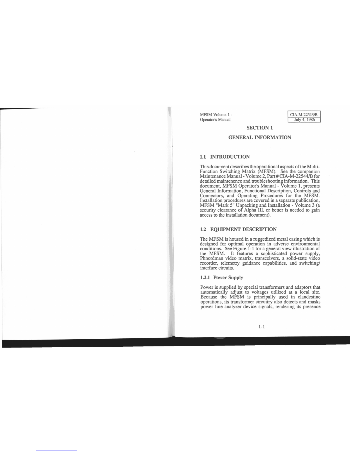
The MFSM is housed in a ruggedized metal casing which is
designed for optimal operation in adverse environmental
conditions. See Figure
1-1
for a general view illustration
of
the MFSM. It features a sophisticated power supply,
Phnordman video matrix, transceivers, a solid-state video
recorder, telemetry guidance capabilities, and switching!
interface circuits.
1.2.1 Power Supply
Power is supplied by special transformers and adaptors that
automatically adjust to voltages utilized at a local site.
Because the MFSM is principally used in clandestine
operations, its transformer circuitry also detects and masks
power line analyzer device signals, rendering its presence
1-1
Page 5
MFSM Volume 1 -
Operator's Manual
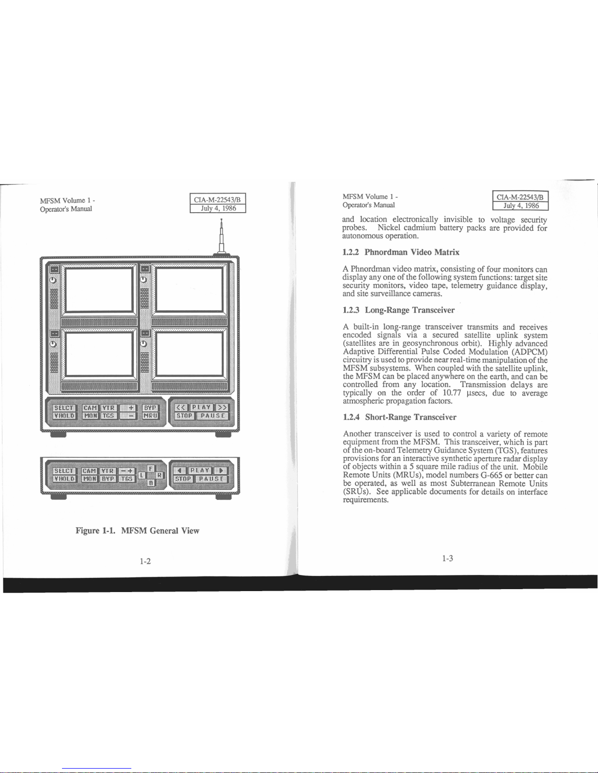
Figure 1-1. MFSM General View
1-2
MFSM Volume
1-
Operator's Manual
and location electronically invisible to voltage security
probes. Nickel cadmium battery packs are provided for
autonomous operation.
1.2.2 Phnordman Video Matrix
A Phnordman video matrix, consistingoffour monitors can
display anyone
of
the following system functions: target site
security monitors, video tape, telemetry guidance display,
and site surveillance cameras.
1.2.3 Long-Range Transceiver
A built-in long-range transceiver transmits and receives
encoded signals via a secured satellite uplink system
(satellites are in geosynchronous orbit). Highly advanced
Adaptive Differential Pulse Coded Modulation (ADPCM)
circuitryis usedto provide nearreal-timemanipulation
of
the
MFSM subsystems. When coupled with the satellite uplink,
the MFSM can be placed anywhere on the earth, and can be
controlled from any location. Transmission delays are
typically on the order
of
10.77
~secs,
duetoaverage
atmospheric propagation factors.
1.2.4 Short-Range Transceiver
Another transceiver is used to control a varietyofremote
equipment from the MFSM. This transceiver, which is part
of
the on-board Telemetry Guidance System (TGS), features
provisions for an interactive synthetic aperture radar display
of
objects within a 5 square mile radiusofthe unit. Mobile
Remote Units (MRUs), model numbers G-665 or better can
be operated, as well as most Subterranean Remote Units
(SRUs). See applicable documents for details on interface
requirements.
1-3
Page 6

MFSM
Volume 1 -
Operator's
Manual
1.2.5 Interfaces
MFSM
Volume 1 -
Operator's
Manual
The MFSM has provisions for a varietyofvideo, audio, and
digital interfaces (including GPIB and RS-232C). An
internal 68000 microprocessor is used to control all MFSM
subsystems, either by direct remote commands or by
programs, which can be transmitted and stored for future
use. Once the MFSM is installed at a remote site, it can be
configured to intercept, process, and emulate significant
aspectsofthat site's command and control network. Video
systems canbemonitored, controlled, and even bypassed
with the on-board Video Tape Recorder (VTR). Data buses
canbeaccessed to provide monitoring and controlofdigital
systems. Automatic error detection and encryption circuitry
assures accurate, undetected operation.
1.3
RELATIONSHIP OF UNITS
Your
Computer
CIA
Central
Hidden
MRUs
MFSM
Complex Site
Video
Control Panel
Figure 1-2 shows all elementsofthe overall system
configuration and the operating environmentofthe MFSM.
The MFSM is installed at a remote site to monitor its
transmissions and control telemetrically guided devices.
Uplink to a secured satellite system transfers data to and
from the MFSM to a central processing system, which can
be accessed through authorized computers or terminals.
Figure
1-2.
Overall System Configuration
Page 7

MFSM
Volume
1 -
Operator's
Manual
,
MFSM
Volume
1 -
Operator's
Manual
SECTION 2
FUNCTIONAL DESCRIPTION
2.1
INTRODUCTION
This section describes only the functional aspectsofthe
MFSM. Refer to Maintenance Manual - Volume II for the
accompanying Section 3 - Theory
Of
Operation. Figure 2-1
presents an overall functional block diagram
of
the MFSM
major subsystems. Bold numbers in the following text
correspond to the circled numbers in Figure 2-1.
2.2
SYSTEM CONTROL
The SELCT pushbutton, 1, is partofthe System Control
circuit (not shown). The pushbutton operates a switch
which selects one
of
four display screens. The screen
selected is active for programming until the SELCT
pushbutton is pressed again. Only one monitor may be
selected for programming at any time. Then the next screen
in a left-to-right and top-to-bottom sequence is activated.
The VHOLD pushbutton, 10 , allows vertical synch
of
an
active screen to be corrected.
2.3
SITE MONITOR FUNCTION
The MFSM is patched into the target site's security system.
The MON pushbutton, 2, allows a remote operator
to
view
what the site monitor operators see
as
they scan their
system. Because most installations utilize a dual monitor
system, the MFSM monitor circuits can be switched
between two separate signals, 3, by either pressing the
MON pushbutton again or pressing the
+/- pushbutton
while in the monitor mode.
2-1
..
o
~cn
o
..
r:
0
~-<
(jj
e
-I
E
:;:;:r.
.
.Q.
:~:
....
-----iJ
Figure
2-1.
Functional Block Diagram
2-2
VI
OJ
(!)
[±]
4:
...J
U.
.&.
t
c
• .2
l:r;:
. .
-'
>
~
~
I
4:
Ill:
W
1:
4:
U
G
Page 8

MFSM
Volume 1 -
Operator's Manual
MFSM
Volume
1 -
Operator's Manual
2.4
VTR
AND
BYPASS
FUNCTION
Surveillance camera video signals can be overidden with
images from the MFSM Video TapeRecordersubsystem. A
bypass switch, 4, allows the target site's currently active
surveillance camera signal to be substituted with a recorded
video signal. The Video Tape Recorderisactivated with the
VTR pushbutton,S. The VTRisactually a solid-state
device which digitizes video signals on up to 38 separate
channels and stores them in a virtual memory. The internal
bubble memory has a 5 gigabyte capacity which is refreshed
every 24 hours. Operation is identical to thatofan analog
VTR, and the controls associated with the subsystem are
also similar.
2.5
TELEMETRY GUIDANCE SYSTEM
The Telemetry Guidance System, 7 , functionsasfollows:
1)
it provides a passive synthetic aperture radar display of all
objects within an immediate rangeof5 square miles, and 2)
it integrates outputs from a motion detector, the target site
digital traffic, and feedback from MRUs. Thus on one
monitor a remote operator can simultaneously view a floor
plan renderingofthe target site, the present locationofan
MRU, the motion
of
site security personnel, and a
representationofwhich surveillance cameras are active
within the display parameters. Although the maximum
rangeofthe TGS is 5 square miles, it displays an immediate
rangeofonly 200 square yards at a time. The TGS is
automatically linked to the movementofany active MRU,
which then causes the display to be scrolled in accordance
with the MRU location.
2-3
2.6
MOBILE REMOTE UNIT
MRUs can be activated by pressing the MRU pushbutton,
8, or
any
of
the motion control pushbuttons.Itis
recommended that the TGS is used in conjunction with this
operation, since MRU models compatible with most MFSM
models do not presently featureaninternal camera.
2.7
CAMERA
The outputoftarget site surveillance cameras can be
~dividually
~~~w~~.
Pressing the CAM pushbutton,9,
mtercepts the live camera for the corresponding channel
selected.
2-4
Page 9

F
MFSM Volume 1 -
Operator's
Manual
SECTION 3
CONTROLS
AND
CONNECTORS
3.1
GENERAL
In
this section the location and functionofall controls,
indicators, displays, and connectors are identified. Note that
this portion
of
the manual does not provide details on theory
oroperation
of
the elements identified. See Section 4ofthis
manual for operating procedures.
3.2 CONTROLS
Refer to Figures 3-1 and 3-2 foranoverall viewofthe
MFSM. The major elements
of
the device are the keypad
control panels, the four raster scan display screens, and
backpanelconnectors.
3.2.1 Keypad Control Panels
Figure 3-3 provides an illustrationoftwo configurations
of
the keypadcontrolpanel. Differentkeypad arrangements are
used, depending on the MFSM model number and the
operator's interfacing computer. They are divided into two
major groups: system control and VTR control. Table 3-1
describes the elements shown in Figure 3-3.
3.2.2 Display Controls
Display controls are shown in Figure 3-4. Operating
procedures andinterpretation
of
these displays are detailed in
Section 4.
3-1
MFSM Volume 1 -
Operator's
Manual
Figures
3-1
and 3-2. Overall MFSM
Views
3-2
Page 10

MFSM
Volume
1 -
Operator's
Manual
MFSM
Volume
1 -
Operator's
Manual
Figure 3-3. Keypad Control Panels
Figure 3-4.
Phnordman
Video Matrix
3-3
]
J
TABLE 3-1. Keypad Control Panel Elements
Item
Nomen-
No.
cIature Description
1 SELCT Used to select screens for activation.
Selection occurs in a left-to-right,
top-to-bottom, sequence.
2 VHOLD
Vertical hold adjust mode switch.
3
CAM
Selects "live" camera for viewing.
4
MON
Gains access to target site internal
closed-circuit security monitors.
Two
circuits are available for viewing:
MON
A and
MON
B.
5
VTR
Activates the Video Tape Recorder.
6 TGS
Activates the Telemetry Guidance
System display on the screen selected.
7
+
Increments channels when in
CAM
and VTR modes. Toggles between site
security monitor circuits when in MON
mode. Adjusts vertical hold
on
some
models.
8
-
Decrements channels when in
CAM
and VTR modes. Toggles between site
security monitor circuits when in MON
mode. Adjusts vertical hold
on
some
models.
9
BYP Toggles
VTR
bypassofsite monitor
channel.
3-4
Page 11

MFSM
Volume
1-
Operator's
Manual
MFSM
Volume
1 -
Operator's
Manual
TABLE
3-1.
Keypad
Control
Panel
Elements
10
MRU
Activates Mobile Remote Unit (MRU).
Only one
MRU
can be active at any
time.
11
«
Rewinds VTR tape.
12
STOP
Stops VTR tape. Causes screen to
show blank until the tape is
played
Indicated by highlight on pushbutton.
13
PLAY
Starts VTR tape. Function activation
is indicated by highlight on pushbutton.
14 PAUSE
Pauses VTR tape. Function activation
is indicated by flashing highlight on
pushbutton. PLAY must be pressed
again to restart tape.
15
»
Advances the VTR tape.
16 L
Used in conjunction with
MRU
mode.
Causes MRU to turn left.
17 F
Used in conjunction with
MRU
mode.
Causes MRU to move forward.
18
B
Used in conjunction with
MRU
mode.
Causes MRU to move backwards.
19
R
Used in conjunction with
MRU
mode.
Causes MRU to turn right.
3-5
3.3
BACKP
ANEL
CONNECTORS
Backpanel connectors are hardwired on site. All cables and
connectors tenninate in special adaptors that interface with
the target site tenninals. Figure 3-5 shows connectors
on
the backpanelofthe MFSM.
3.3.1 Video
Inputs/Outputs
~amera
inputs are taken directly from tapsofa remote site's
vIdeo control center.
Up
to 38 channels are provided. The
MFSM
solid-state recorder bypass output connectors
(labelled
MON
OUTPUTS) are patchedback into the remote
site swi.tching unit. Bias and phasing mismatches are
automatically compensated for. A synch signal from the
MFSM
control microprocessor is included with every VTR
output to allow for precise synchronization with the target
system's timing devices.
3.3.2
Audio
Inputs/Outputs
Alt~ou&h
the
BNC
connect?rs for. monitor inputs also carry
audIO
~lgnals,
the
MFS~
IS
eqUlpped with 10 RCA-type
stere? mput and output Jacks. These are used for ancillary
buggmg purposes. These jacks can also be interfaced with
the Digital Audio Synthesizing Unit (DASU), Part # CIAUY
~-007/9~
for special highly sophisticated jamming and
audio alteration purposes.
3.3.3
Data
Acquisition
Connectors
GPffi and RS-232C connectors form the lower partofthe
backplane panel.
The
target site's digital traffic is routed
through t.hese connectors. In addition, serial-to-parallel
probes, SIgnature analyzers, serial interface probes trace
modules, remote control devices, etc. can be
conne~ted
to
theseports. Seethecompanion
MFSM
Maintenance
Manual-
Volume 2 for details on connectors.
3-6
Page 12

MFSM
Volume
1 -
Operator's
Manual
MFSM
Volume
1-
Operator's
Manual
SECTION 4
OPERATING PROCEDURES
CIA-M
-2254
31B
July 4, 1986
CAMERA
IIlPUTS
~~~Il
~~~~
Ll?_~_·I
I?_~
I'OVER
HANUALI
Jo
II
RS-232C
aPIB
•
IE
ltIW-===
2~2.
**¥E
e
FUS£
Figure 3-5. Backpanel Connectors
3-7
4.1 GENERAL
This section describes detailed operating procedures for the
following modes
of
MFSM operation:
• Monitoring
• VTR
• Bypass
• TGS
andMRU
Operating procedures for menus and displays used to control
parameters are presented in this section. Initial tum-on
procedures, basic programming rules, and operating modes
are discussed, respectively.
4.2 TURN-ON PROCEDURES
Gaining access to the MFSM from an unauthorized
microcomputer terminal is virtually impossible. Uplinks are
possibleonly when originatedfrom centralcomputercontrol
to offsite terminals.
4.3 BASIC PROGRAMMING RULES
A hand shaped cursor is used to "press" the appropriate
pushbuttons
on
the
MFSM
front panel.Onmicrocomputers
configured with a standard joystick the cursor is positioned
with the control column, and the desired pushbutton is
activated by pressing the joystick switch (typically #1). On
micrQcomputers configured with a mouse the cursor is
positioned by moving the mouse, and the desired
4-1
Page 13

CIA-M-22543/B
July4,1986
MFSM
Volume
1 -
CIA-M-22543/B
Operator's Manual July4,1986
pushbuttonisactivated by pressing the switch on topofthe
mouse once.
When a pushbutton has been pressed, the finger
of
the
cursor changes to a down position, and the lettering on the
button is highlighted with color to indicate the active status.
Depending on the pushbutton pressed (and the function in
operation) the highlight may be momentary, it may continue
as
long as the button is held down, or it may stay on until
the pushbutton is pressed a second time.
4.3.1 Selecting Display
To select a display, press the
SELCT
pushbutton. The
channel indicator for the next display in a left-to-right, topto-bottomorder will immediately flash. The channel number
is
changed by pressing the +or- pushbuttons.
4.3.2 Adjusting Vertical Hold
Sometimes the vertical hold must be adjusted on a display.
To do this, perform the following procedure:
1.
Press the
SELCT
pushbutton to select the desired
display.
2.
On systems equipped with a joystick:
• Move the hand cursor
to
the
VHOLD
pushbutton.
• Press and hold the joystick control button.
• The
VHOLD
is
highlighted
• While still
pressin&
the joystick control button,
move the column forward to control the rate
of
bottom-to-top vertical roll, and back to control
the rate
of
top-to-bottom roll.
MFSM
Volume
1 -
Operator's Manual
3.
On systems equipped with a mouse:
• Press and hold the
VHOLD
pushbutton.
• The
VHOLD
is
highlighted.
• Press the
+ or - button
to
control the rate
of
vertical roll.
• Press the
VHOLD
pushbutton again.
4.4
OPERATING
MODES
The MFSM Monitoring, VTR, Bypass, and TGSIMRU
functions provide extremely powerful and flexible
capabilities for sophisticated real-time remote covert
activities.
In
the
MON
mode,anoperator may view a site's
internal monitoring system.
In CAM mode, the operator
may also view individual cameras independent
of
it's
monitoring system. The VTR mode allows for playback
and analysis
of
all the site's recorded activities. The BYP
mode enables
an
operatortointerceptaninternal monitoring
system and substitute its current channel with a taped image
corresponding to the same channel. Finally, the
TGS
and
MRU
modes provide information concerning the relative
displacement and disposition
of
hostile counterintelligence
forces, and allows command and control over friendly
intelligence elements. Successful use
of
the MFSM,
therefore, depends on the ability
of
the operator to
manipulate all the resources available to carry out the
desired mission.
4.4.1 Monitoring
Monitoring takes place in two modes: viewingofa remote
site internal video security monitoring circuits, and viewing
elements
of
those circuits independentofthe site central
control.
Page 14

MFSM Volume 1 -
Operator's Manual
CIA-M-22543/B
July 4, 1986
MFSM Volume 1 -
Operator's Manual
CIA-M-22543/B
July 4, 1986
4.4.1.1
Viewing Security Monitors.
To
gain access
to internal security monitors, perfonn the following
procedure:
1.
Select the desired display monitoronthe MFSM.
2.
Press the MON pushbutton.
3.
The
default monitor circuit is "A". Verify that the
monitor status display indicates"SECURITY
MON
A (orB)".
4.Tochange the current monitor, press the MON
pushbutton.
5. Verify that the monitor status display indicates the
alternate monitor circuit.
4.4.1.2 Viewing Independent Cameras. Individual
surveillance cameras at the site can be isolated for viewing.
To
view a separate camera, the appropriate channel for that
camera must be activated. Perfonn the following procedure:
1.
Selectthe desired display monitoronthe MFSM.
2.
Press the CAM pushbutton.
3.
Verify that the monitor status display indicates
"LNE".
4. Press the + pushbutton to incrementchannels and
the • pushbutton to decrement channels.
4.4.2
Video Tape Recorder Operation
The Video Tape Recorder modeofoperation is useful for
display and analysis
of
pre-recorded activity. Recording is
continuously automatic,
so
there arenoprovisions for
"recording" an independent event, as with a standard VTR.
When a channel is set for display, the taped material is
transferred from a special buffer.
When a display
on
the
MFSM
has been selected and the
VTR
pushbutton has been pressed, the VTR will then
function in a manner similar to normal analog devices. See
Section
3 for
an
explanationofpushbutton functions
associated with the VTR. The display status indicates
"TAPE" when the
VTR
is active.Tochange the currenttape
channel number, press either the
+
or·
pushbutton.
The synch signal that is recorded with the original image is
automatically shownduringplayback. Thatsignal is present
on the bottom part
of
the screen as numbers that correspond
to the minute and second
of
a one hour period. Shuttle
search is possible by pressing the
PLAY pushbutton and
then pressing the
»
or
«buttons.
A speeded image
of
the recorded material will be shown, along with synch
numbers at the bottom.
4.4.3
Bypass
The bypass mode allows the recorded image from a
VTR
channel toreplace its corresponding surveillance camera.
To
perfonn a monitor bypass, do the following:
1.
Use oneofthe
MFSM
displays to show the
VTR
screen.
2.
Select the
VTR
channel to be bypassed (using +
or
• pushbutton).
3.
If
necessary, advanceorrewind the
VTR
until the
time synch values match those shown on a real-time
display.
4.
Press the PLAY buttononthe
VTR.
5. Press BYP to bypass the surveillance camera signal
with tape.
6.
Verify that the monitor status display indicates
"BYPASS CAMERA".
Page 15

MFSM Volume 1 -
Operator's Manual
CIA-M
-22543/B
July 4, 1986
MFSM Volume 1
-
Operator's Manual
CIA-M-22543/B
July 4, 1986
To
disable the bypass,dothe following:
1.
Select
MFSM
display showing the bypassed
camera
2. Press the
BYP
pushbutton to return to nonnal
V1R
function.
WA!R{NIING
SOME
SECURITY
SYSTEMS
CAN
DETECT
WHENASYNCHRONIZATION
ERROR
HAS
OCCURRED.
BE
ABSOLUTELY
CERTAIN
THAT
THE
CORRECT
TIME
SYNCH
SIGNALISPRESENT
ON
THE
BYPASS
CHANNEL.
4.4.4
TGS
and
MRU
Modes
When
the Telemetry Guidance System screen is present
on
any
of
the
MFSM
displays, all pertinent information
regarding active cameras, site personnel placement,
navigational infonnation, and
MRU
location is provided.
To
display the
TGS
screen:
1.
Select the desired display monitor on the MFSM.
2. Press the
TGS
pushbutton.
3. Verify that the monitor status display indicates
"TGS - ". The current direction
of
the
MRU
is showninthe space after the dash.
Since location
of
an active
MRU
can also be shown relative
!o its
~urroundings,
~t
is best to control the
MRU
in conjunct-
Ion
WIth
the TGS display. Figure 4-1 explains the symbols
used on the TGS screen.
4.4.4.1
Controlling
MRU
Movement.Tocontrol an
MRU
displayedonthe TGS, perfonn the following
procedure:
1.
On
systems equipped with a joystick:
a) Move the hand cursor to the
MRU
pushbutton.
b) Press and release the joystick control button.
c) The
MRU
button is highlighted.
d) Move the column forward to move the
MRU
forward, and back to move the
MRU
backwards.
e) Move the column to the left to turn the
MRU
to
the left, and to the right to turn the
MRU
to the
right.
f)
Note that the TGS status display indicates the
direction (EAST, WEST,
NORm,orSOUill)
the
MRU
is facing.·.
g) Centering the control column stops the
MRU
in
its current position.
h) Press the
MRU
button again to release the
MRU
function.
i) Verify that the
MRU
button is no longer
highlighted.
On
systems equipped with a mouse:
a) Press and hold the F button to move the
MRU
forward, and the B button to move the
MRU
backwards.
b) Press and hold the L button to turn the
MRU
to
the left,
and the R button to turn the
MRU
to the right.
c) Note that the monitor status display indicates the
direction (EAST, WEST,
NORm,orSOUill)
the
MRU
is facing.
Page 16

MFSM Volume 1 -
Operator's Manual
4.5
SECRECY
WARNING
CIA-M-22543/B
July
4,
1986
The content
of
this manual is
of
the highest
"TOP
SECRET" classification. Do not
r~move
this document
from its locked
fIles. Operatives with proper security
clearance will receive sealed copies.
It
is unlawful to copy
this MFSM document onto magnetic tape or disk, or by any
optical, chemical, or mechanical means.
Site
Security
Personnel
Active
Mon~ors
MMMM~=-
MRU
Heading
Figure
4-1.
TGS Screen
4-8
 Loading...