

Page 1

Actiontec
54 Mbps Wireless
Network Camera
User Guide
Page 2

Page 3

Table of Contents
CHAPTER 1 INTRODUCTION..............................................................................................1
Overview ............................................................................................................................ 1
Features......................................................................................................................... 1
Internet Features ........................................................................................................... 2
Security Features ..........................................................................................................2
Wireless Features.......................................................................................................... 2
Physical Details.................................................................................................................. 3
Front Panel.................................................................................................................... 3
Rear Panel..................................................................................................................... 3
Package Contents ..............................................................................................................5
CHAPTER 2 BASIC SETUP ................................................................................................... 6
System Requirements........................................................................................................ 6
Installation ......................................................................................................................... 6
Setup ................................................................................................................................... 8
Setup Procedure............................................................................................................8
CHAPTER 3 ADVANCED VIEWING SETUP ................................................................... 14
Introduction ..................................................................................................................... 14
Adjusting the Video Image ............................................................................................. 14
To Adjust the Video Image: .......................................................................................14
Controlling User Access to the Video Stream ............................................................... 16
To Enable This Feature:.............................................................................................. 16
Operation .................................................................................................................... 16
Making Video Available From the Internet.................................................................. 17
Wireless/Ethernet Network Camera Setup ................................................................. 17
Router/Gateway Setup................................................................................................ 18
Viewing Via the Internet ............................................................................................ 19
Motion Detection/E-mail Alerts .....................................................................................20
To Use Motion Detection/E-mail Alert ...................................................................... 20
CHAPTER 4 WEB-BASED MANAGEMENT ....................................................................22
Introduction ..................................................................................................................... 22
Connecting to the Camera .............................................................................................. 22
Connecting Using Your Web Browser ....................................................................... 22
Welcome Screen............................................................................................................... 23
View Video Screen........................................................................................................... 24
Administration Menu...................................................................................................... 25
System Screen .................................................................................................................. 25
Network Screen................................................................................................................ 27
WEP Screen................................................................................................................ 30
WPA-PSK Screen....................................................................................................... 32
Image Screen.................................................................................................................... 32
User Screen ......................................................................................................................34
Add/Modify User Screen............................................................................................ 35
E-mail Screen................................................................................................................... 36
Status Screen.................................................................................................................... 38
Upgrade Firmware Screen .......................................................................................... 40
CHAPTER 5 VIEWING & RECORDING........................................................................... 41
Overview ..........................................................................................................................41
Installation ....................................................................................................................... 41
System Tray Icon............................................................................................................. 42
i
Page 4

Main Screen ..................................................................................................................... 42
Adding Cameras to the Camera List ............................................................................. 44
Adding Cameras on the Internet ................................................................................. 45
Modifying an Existing Camera................................................................................... 46
Viewing Live Video .........................................................................................................47
Recording Video .............................................................................................................. 48
Recording Preferences................................................................................................ 48
Live Recordings.......................................................................................................... 49
Files ............................................................................................................................50
Scheduled Recordings ................................................................................................51
Viewing With Your Web Browser ................................................................................. 53
Viewing Over Your LAN ........................................................................................... 53
Viewing Via the Internet ............................................................................................ 55
CHAPTER 6 TROUBLESHOOTING .................................................................................. 57
Overview .......................................................................................................................... 57
Problems........................................................................................................................... 57
APPENDIX A SPECIFICATIONS........................................................................................59
Actiontec 54 Mbps Wireless Network Camera............................................................. 59
Regulatory Approvals ..................................................................................................... 60
CE Approvals .............................................................................................................60
Limited Warranty ........................................................................................................... 61
Copyright 2004. All Rights Reserved.
Document Version: 1.0
All trademarks and trade names are the properties of their respective owners.
ii 1
Page 5
Chapter 1
Introduction
This chapter covers the features, components, and capabilities of the
Actiontec 54 Mbps Wireless Network Camera.
1
Overview
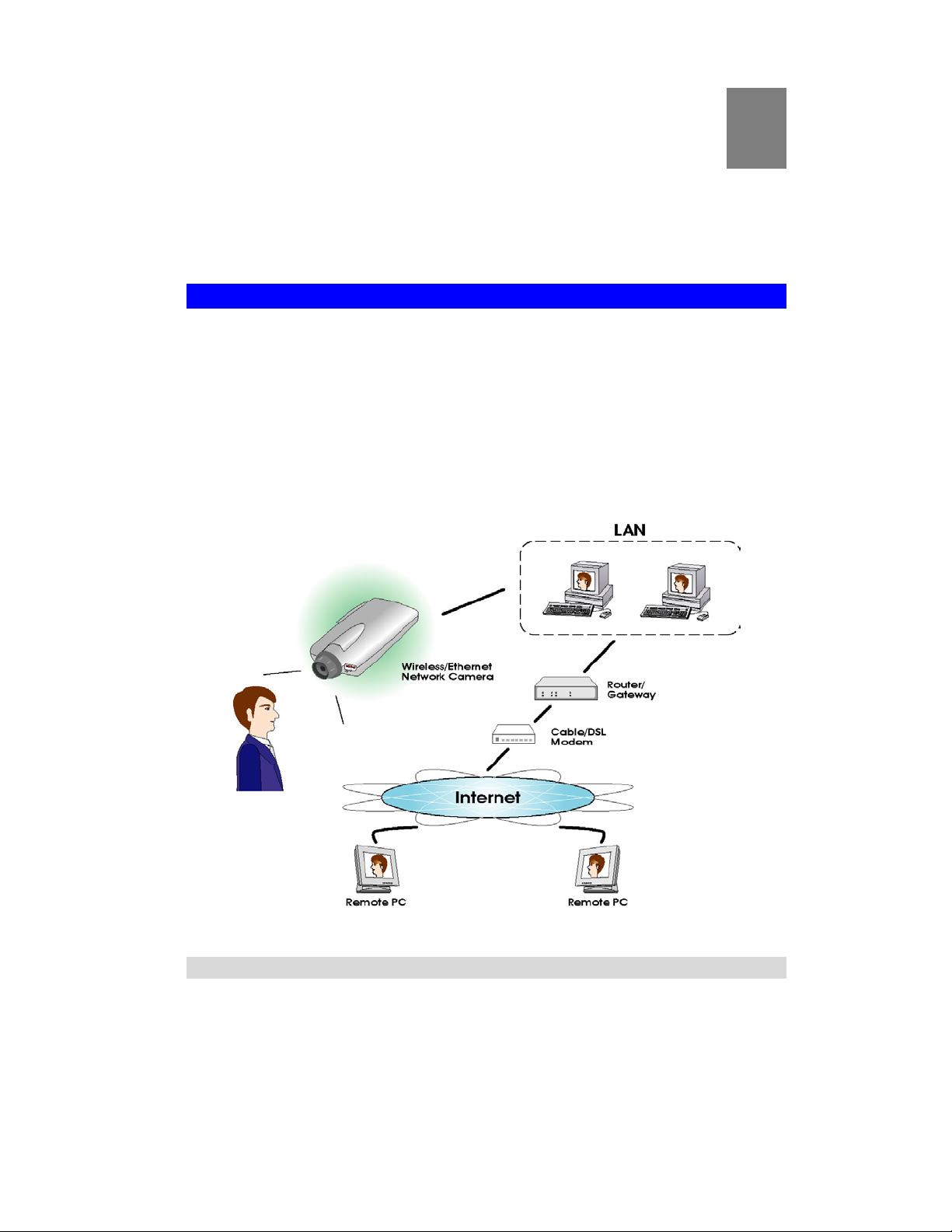
The Actiontec 54 Mbps Wireless Network Camera has an integrated microcomputer and a high
quality CMOS digital-Image-Sensor, enabling it to display high quality live streaming video
over your wired LAN, the Internet, and for the Camera, an 802.11g Wireless LAN.
Using enhanced MPEG-4 technologies, the Camera is able to stream high quality video and
audio directly to your PC. The high compression capabilities of MPEG-4 reduce network
bandwidth requirements to amazingly low levels.
A convenient and user-friendly application is provided with the Camera for both viewing and
recording video. If necessary, you can even view video using your Web browser on a variety of
software platforms.
Figure 1: Actiontec 54 Mbps Wireless Network Camera
Features
• Standalone Design. The Camera is a standalone system with built-in CPU and video
encoder. It requires only a power source and a connection to your LAN or wireless LAN.
Suitable for Home, Business, or Public Facilities. Whether for home, business or
•
public facility surveillance, or just for entertainment and fun, the Camera has the features
you need.
Page 6

•
Multi-Protocol Support. Supporting TCP/IP networking, SMTP (E-mail), HTTP, and
other Internet related protocols, the Camera can be easily integrated into your existing
network.
Easy Configuration. A Windows-based “Wizard” application is provided for initial
•
setup. Subsequent administration and management can be performed using a standard Web
browser. The administrator can configure and manage the Camera via the LAN or Internet.
• Viewing/Recording Utility. A user-friendly utility is provided for viewing live video.
For periods when you are absent or for scheduled recording, this utility also allows you to
record video to an ASF file on your computer. The recorded files are in a standard
Windows Media format, and thus usable by a wide variety of programs, if required.
• Motion Detection. This feature will send you an e-mail when motion is detected. The
Camera will compare consecutive frames to detect changes caused by the movement of
large objects. This function only works indoors due to the sensitivity of the CMOS sensor.
If desired, a short video can be included as an attachment to the e-mail.
Audio Support. You can listen as well as look! Audio is included with the video if
•
desired. You can use either the built-in microphone or an external microphone.
Internet Features
• User-definable HTTP port number. This allows Internet gateways to use “port
mapping” so the Camera and a Web server can share the same Internet IP address.
DDNS Support. In order to view video over the Internet, users must know the Internet
•
IP address of the gateway used by the Camera. If the gateway has a dynamic IP address,
DDNS (Dynamic DNS) is required. Since many existing gateways do not support DDNS,
this function is incorporated into the Camera.
NTP (Network-Time-Protocol) Support. NTP allows the Camera to calibrate its
•
internal clock from an Internet time-server. This ensures the accuracy of the time stamp on
video from the Camera.
Security Features
• User Authentication. If desired, access to live video can be restricted to known users.
Users will have to enter their username and password before being able to view the video
stream. Up to 20 users can be entered.
Password-Protected Configuration. Configuration data can be password protected, so
•
that only the Camera administrator can change it.
Wireless Features
• Standards Compliant. The wireless router complies with the IEEE802.11g (DSSS)
specifications for wireless LANs.
Supports both 802.11b and 802.11g Wireless Stations. The 802.11g standard
•
provides for backward compatibility with the 802.11b standard, so both 802.11b and
802.11g wireless stations can be used simultaneously.
Speeds to 54Mbps. All speeds up to the 802.11g maximum of 54 Mbps are supported.
•
Wired and Wireless Network Support. The Camera supports both wired and wireless
•
transmission.
Security WEP (64-, 128-bit) and WPA-PSK support on the wireless interface is
•
provided.
2
Page 7
Physical Details
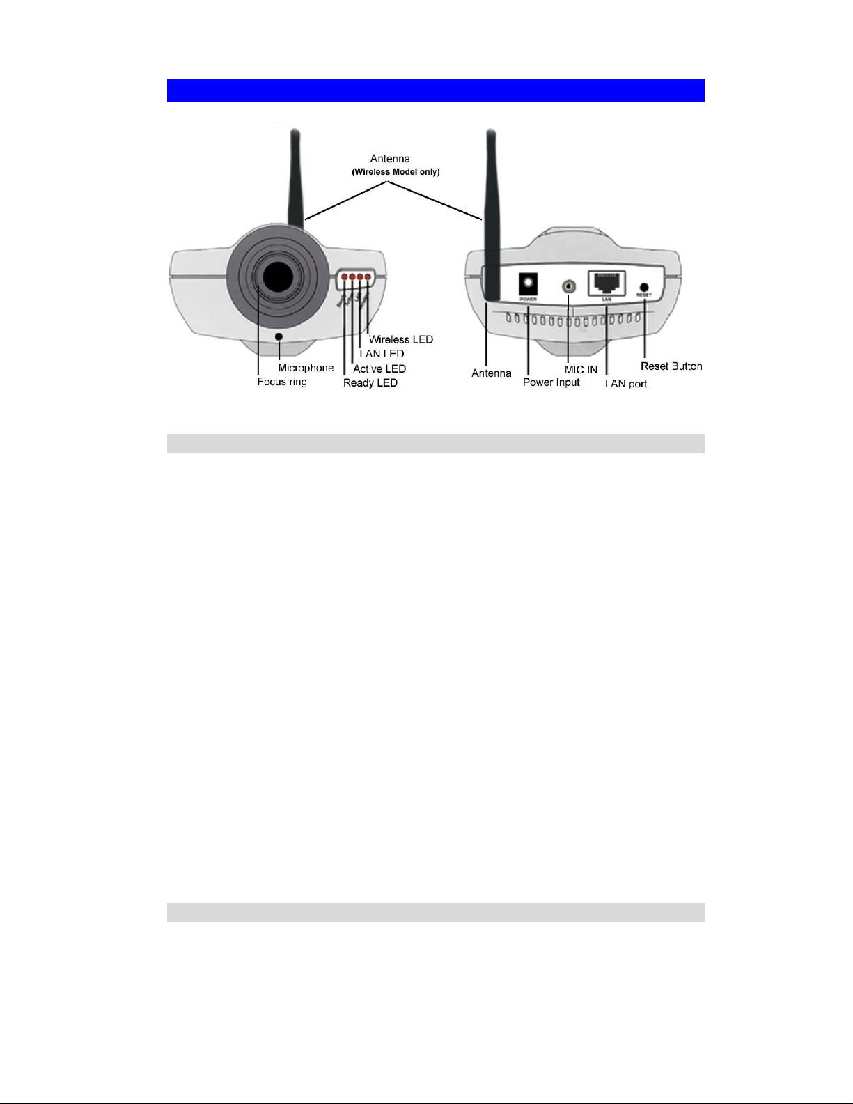
Front Panel
Figure 2: Camera: Front and Back Views
Focus Ring
Microphone
Ready LED
Active LED
LAN LED
Wireless LED
Normally, it is not necessary to adjust the focus. The default focus
range is from 1 meter (3 feet) to infinity. If the image is not clear, try
adjusting the focus.
The built-in microphone is mounted on the front. There is also a
connection for an external microphone on the rear. Connecting an
external microphone will disable the built-in microphone.
On - Power on.
Off - No power.
Blinking - The “Ready” LED will blink during start up. This will
take 15 to 20 seconds.
Off - Idle.
Blinking - The Camera is providing a live video stream to at least
one viewer.
On - LAN port is connected to a hub or switch.
Off - LAN port is not connected.
Blinking - Data is being transmitted or received via the LAN port.
On - Wireless interface is active.
Off - Wireless interface is not available.
Blinking - Data is being transferred via the wireless interface.
Rear Panel
Antenna
Attach the supplied antenna here. The antenna is adjustable; best
results are usually obtained with the antenna positioned vertically.
3
Page 8

Power Input
MIC In
LAN port
Reset Button
Connect the supplied power adapter here.
If required, an external microphone can be attached here. Attaching
a microphone here will disable the built-in microphone on the front.
Microphones designed for use with computers are usually
compatible with this microphone input.
Use a standard LAN cable to connect your Camera to a
10/100BaseT hub or switch.
Note:
Attaching the LAN cable to the Camera disables the wireless
interface. Only one interface can be active at any time.
This button has two functions:
• Restore Default IP Address - When pressed and released, the
Camera’s IP address will be automatically obtained from the
DHCP server.
• Restore Default IP Address, Administrator ID, and
Administrator password - When pressed and held for three
seconds, the IP Address, Administrator ID, and Administrator
Password settings will be set to their default values.
• IP Address: automatically obtained from the DHCP server
• Administrator ID: administrator
• Administrator Password: null (no password)
Note: After this procedure is completed, the Ready LED will blink
three times to confirm that the reset was completed successfully.
4
Page 9

Package Contents
The following items should be included: If any of these items are damaged or missing, please
contact your dealer immediately.
1. Actiontec 54 Mbps Wireless Network Camera
2. Installation CD-ROM
3. Quick Installation Guide
4. Power Adapter
5. Base, Stand, and Swivel Connector
6. Extender Unit
7. Mounting Screws
8. Antenna
5 6
Page 10
Chapter 2
Basic Setup
This chapter provides information about installing and configuring the
Actiontec 54 Mbps Wireless Network Camera.
System Requirements
• To use the LAN interface, a standard 10/100BaseT hub or switch and network cable is
required.
• To use the wireless interface on the Camera, other wireless devices must be compliant
with the IEEE 802.11b or IEEE 802.11g specifications. All wireless stations must use
compatible settings.
Installation
2
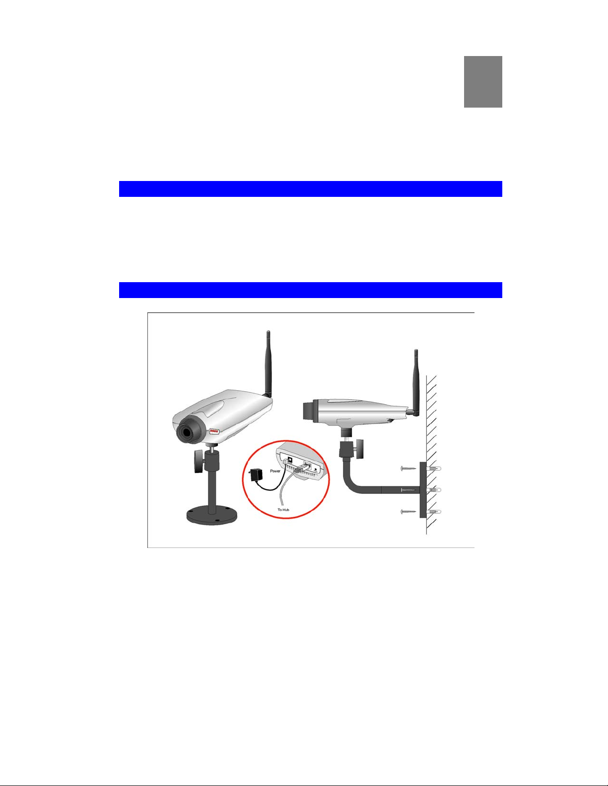
Figure 3: Camera Installation
1. Mount the Camera on the supplied base and stand.
Screw the supplied antenna to the mounting point on the rear of the Camera.
Join the base, stand, and swivel connector to the camera, as shown in the diagram above.
2. Connect the LAN cable.
Connect the Camera to a 10/100BaseT hub or switch.
Page 11

Activating the LAN interface disables the wireless interface,
because only one interface can be active. The LAN interface is
recommended for initial configuration.
The default wireless settings for the Camera are:
Mode: Infrastructure
ESSID: Actiontec
WEP: Disabled
3. Adjust the Antenna
Screw the antenna to the rear mounting point of the Camera, then adjust the antenna to an
upright position to improve wireless reception.
4. Power Up
Remember, before connecting the power adapter, the LAN cable must be connected to the
Camera.
Connect the supplied power adapter to the Camera and power up. Use only the power
adapter provided. Using a different one may cause hardware damage.
4. Check the LEDs
• The Ready LED will turn on briefly, then start blinking. It will blink during startup, which
takes 15 to 20 seconds.
After startup is completed, the Ready LED should remain ON.
• The Active LED should be OFF.
It will flash when anyone is viewing live video.
• Either the LAN LED OR the Wireless LED should be ON.
For more information, refer to “Front Panel” in Chapter 1.
7
Page 12
Setup
Initial setup should be performed using the Setup Wizard. This program can locate the Camera
even if its IP address is invalid for your network. You can then configure the Camera with
appropriate TCP/IP settings for your LAN.
Subsequent administration can be performed with your Web browser, as explained in chapter
3, “Web-based Administration.”
Setup Procedure
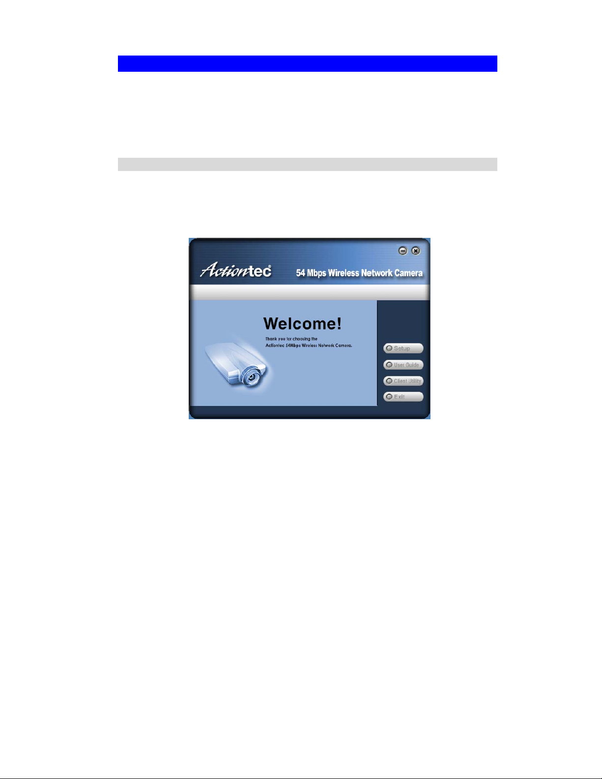
1. Insert the supplied CD-ROM into your drive. If the setup program does not start
automatically, run Setup.exe in the root folder.
• You will see the Welcome screen shown below.
• Click the Setup button to start the “Setup Wizard.”
"
Figure 4: Welcome Screen
8
Page 13
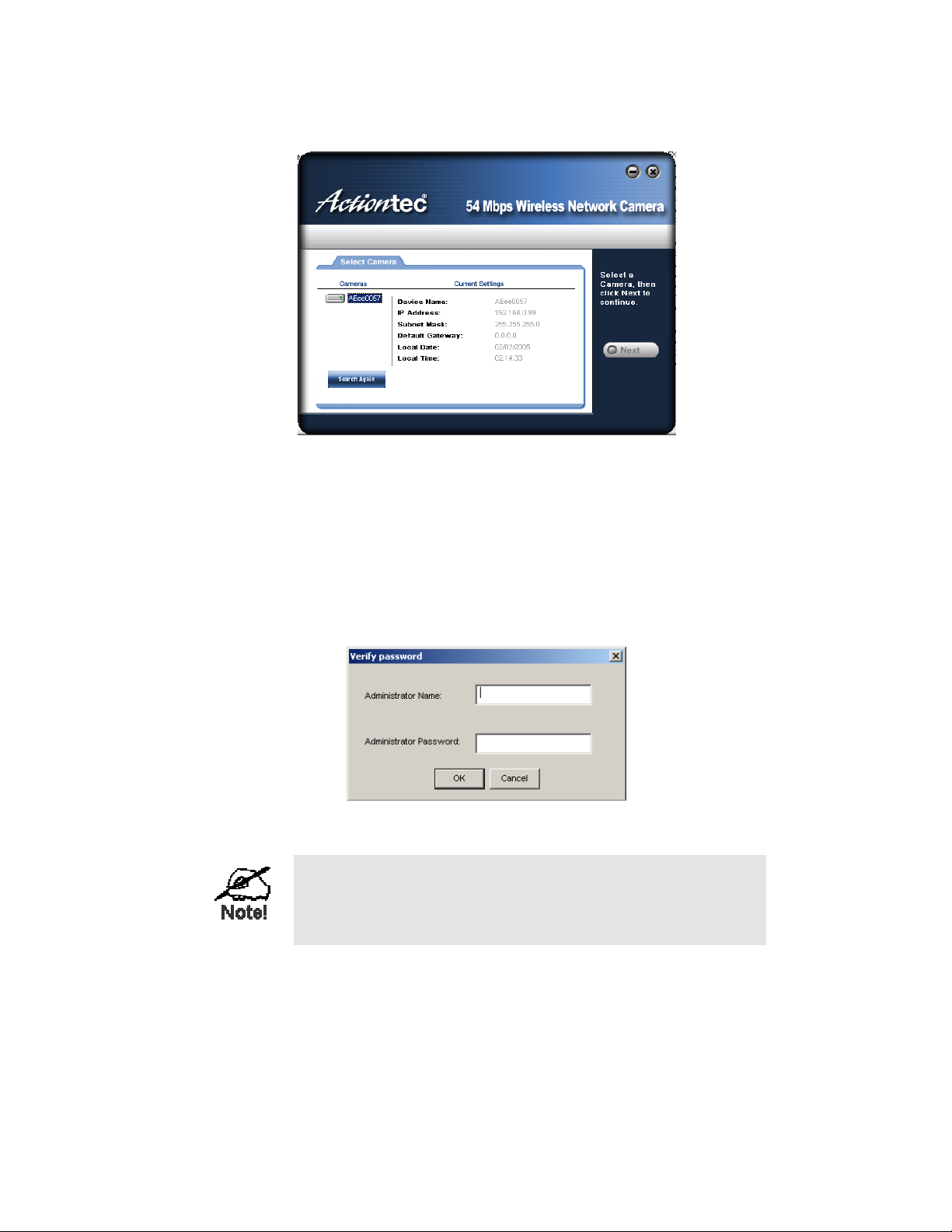
2. The next screen lists all of the Cameras on your LAN.
Figure 5: Camera List Screen
• Select the desired Camera from the list on the left. The current settings for the selected
Camera will be displayed in the table on the right.
• Click Next to continue.
3. You will be prompted for an administrator name and password.
• If using the default values, enter administrator for the name, and leave the password
blank.
• Otherwise, enter the Administrator ID and Password you previously set on the User
screen.
Figure 6: Password Dialog
The Administrator ID and password can be set on the User
screen of the Web interface. The Web interface can be
accessed by clicking Web UI on the final screen of the
Wizard.
9
Page 14
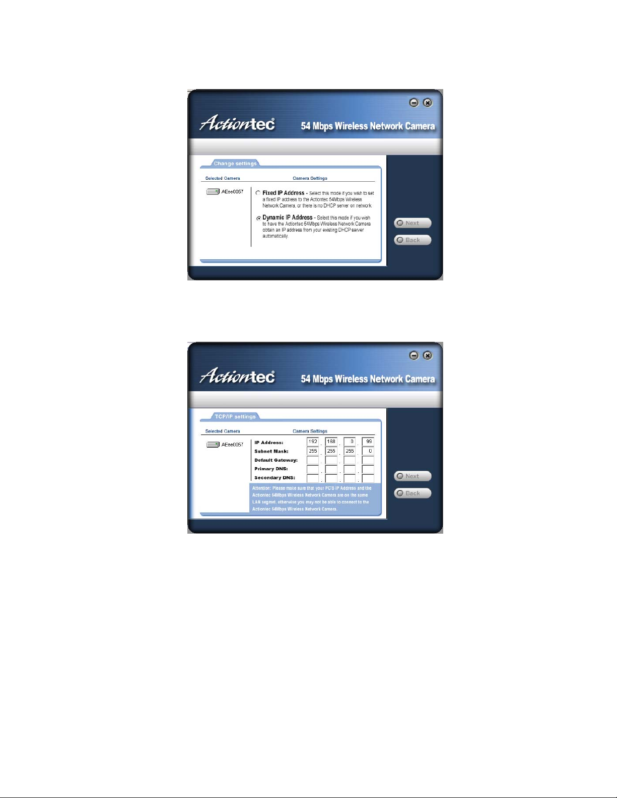
4. On the following TCP/IP screen, shown below, choose Fixed IP or Dynamic IP. Dynamic
IP address is recommended.
Figure 7: Fixed or Dynamic IP Selection
Click Next to continue.
5. If you chose Fixed IP Address, the TCP/IP Settings screen appears.
Figure 8: TCP/IP Settings
• Enter an unused IP Address from within the address range used on your LAN.
• The “Subnet Mask” and “Default Gateway” fields must match the values used by
computers on your LAN.
• The “Primary DNS” address is required in order to use the e-mail alert or Dynamic
DNS features. Enter the DNS (Domain Name Server) address recommended by your
ISP.
• The “Secondary DNS” is optional. If provided, it will be used if the Primary DNS is
unavailable.
Click Next to continue.
10
Page 15
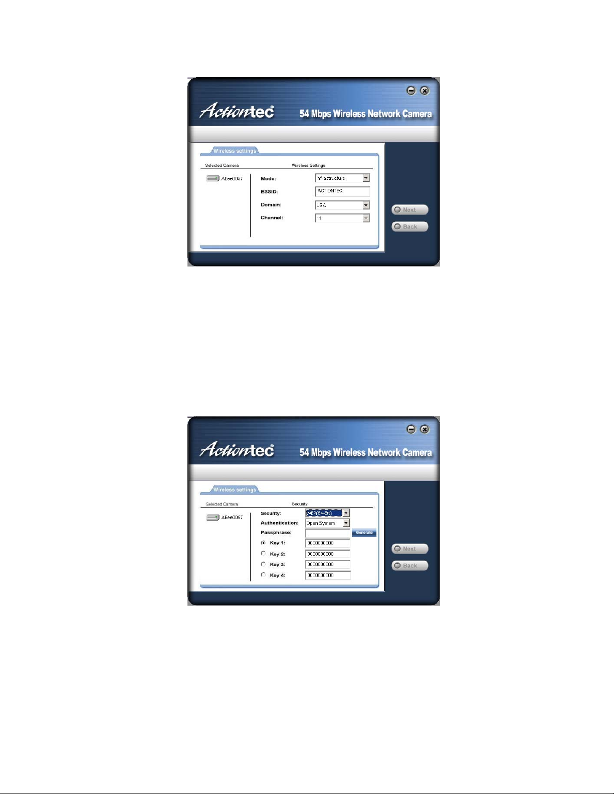
6. The “Wireless Settings” screen appears.
Figure 9: Wireless Settings
• Mode - If you have an access point or wireless broadband router, select
Infrastructure. Otherwise, select Ad-hoc.
• Authentication Type - Select the value used on your LAN.
• ESSID - Enter the value used by your other wireless devices.
• Domain - Select the domain to match your location.
• Channel - For Ad-hoc mode, select the channel used by your other wireless devices.
(For Infrastructure mode, the access point determines the channel used.)
7. Click Next to continue to the “Security” screen, shown below.
Figure 10: WEP Key Settings
• WEP Encryption - Select the option used on your wireless LAN.
11
Page 16
• Keys - If using WEP, the default key must match the key used on your other wireless
stations. The other keys are optional.
You can enter the key value directly, or generate a key by entering a string into the
“Passphrase” field, and clicking the “Generate” button.
If using WPA-PSK on your access point or router, enter the same pre-shared key. This
is an alphanumeric between 8 and 63 characters long, and is case-sensitive.
Click Next to continue to the following screen.
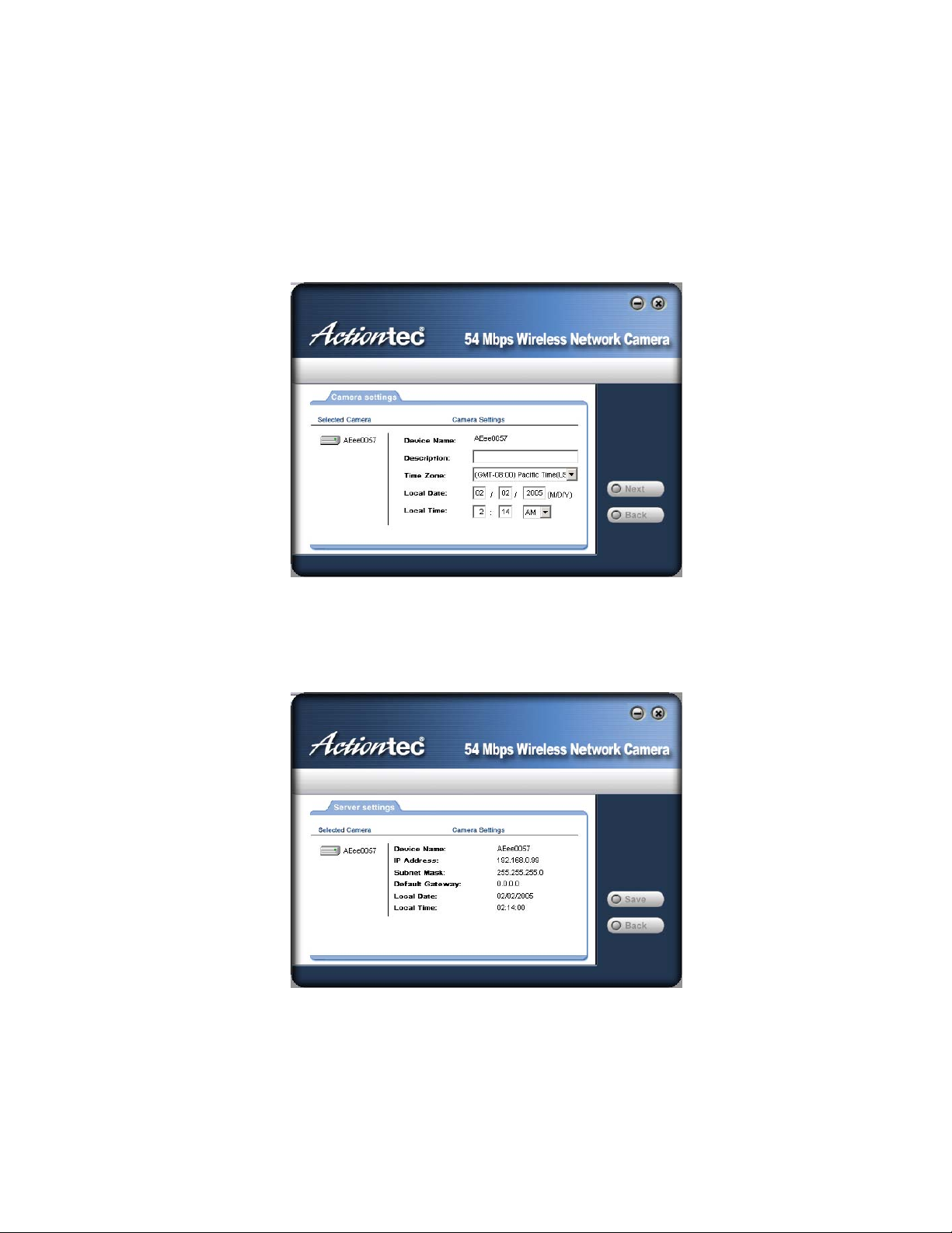
8. This screen allows you to enter a suitable description of the Camera, and set the correct
time zone, date, and time. Make any desired changes, then click Next to continue.
Figure 11: Camera Settings
9. The next screen, shown below, displays all details of the Camera.
• Click Save if the settings are correct.
• Click Back to modify any incorrect values.
Figure 12: Save Settings
12
Page 17

10. After clicking Save, you will see the screen below.
Figure 13: Final Screen
If desired, you can click Web UI to connect to the camera using your Web browser.
11. Click Exit to end the Wizard.
Setup is now complete.
13 14
Page 18

Chapter 3
Advanced Viewing Setup
This chapter provides information about the optional settings and advanced
features for viewing video on the Actiontec 54 Mbps Wireless Network
Camera, and is aimed at experienced network administrators only.
3
Introduction
After setting up the Camera, it can immediately be used by all users on your LAN.
Refer to chapter 5, “Viewing & Recording,” for details on viewing and recording live video.
This chapter describes some additional settings and options for viewing live video:
• Adjusting the video image
• Controlling user access to the live video stream
• Making video available from the Internet
• Using the “Motion Detection/E-mail” feature
Adjusting the Video Image
If necessary, the Camera Administrator can adjust the video image. Settings are provided for:
• Image size - Select the desired size. The larger sizes require greater bandwidth.
• Image quality - This determines the degree of compression applied to the video stream.
Higher quality requires greater bandwidth.
• Power Line Frequency - Select 50Hz or 60Hz power line frequency, depending on
what’s used in your region. The correct setting will improve the picture quality under
florescent lighting.
• Exposure - Adjust the brightness of the image if the “Auto-Exposure” setting does not
give satisfactory results.
• Color Adjustment - Red, green, blue intensity can be adjusted.
• Time Stamp - If enabled, the time will be displayed on the video image.
• Text Overlay - If enabled, up to 20 characters can be superimposed on the video image.
This is useful for identifying the camera.
• Audio - If desired, audio can be included in the video stream.
To Adjust the Video Image:
1. Connect to the Web-based interface of the Camera. (See chapter 4, “Web-based
Management,” for details.)
Page 19
2. From the “Administration” menu, select Image. You will see a screen similar to the one
shown below.
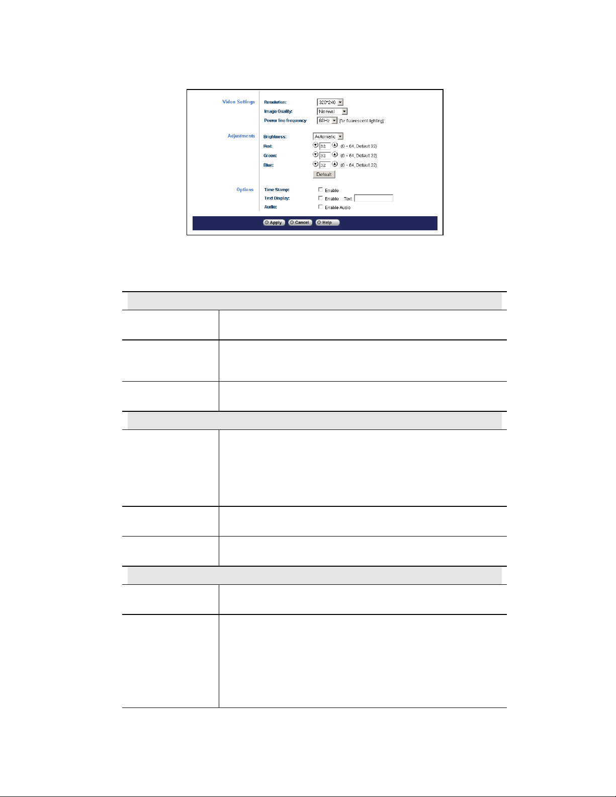
Figure 14: Image Screen
3. Make the required adjustments, as explained below, and save your changes.
Video Settings
Resolution
Image Quality
Power Line
Frequency
Adjustment
Brightness
Red, Green, Blue
Default Button
Options
Time Stamp
Select the desired video resolution. The default resolution is set to
320*240.
Select the desired image quality. The default “Image Quality” is set
to “Normal.”
Note: Higher image quality requires more bandwidth.
Select the power line frequency (50Hz or 60Hz) used in your region,
to improve the picture quality under florescent lighting.
Select Automatic or Manual.
When set to the default setting, Automatic, the Camera adjusts the
brightness automatically based on the current environment.
If you want to adjust the brightness manually, select Manaul. You
can then enter the desired value.
Adjust these color settings to the preferred values. Note: When
Automatic is selected, this setting will not take effect.
Clicking this will set all the “Adjustment” fields to their default
values. You must click Apply to save these changes.
Enable the check box if you want the time to be displayed on the
video image.
Text Display
Audio
If you want text to be displayed on the video image, enable this
feature by checking the check box. You can enter text up to 20
characters. This feature is often used to identify a Camera when
multiple Cameras are installed.
If you want audio to be included with the video, enable this option.
Some bandwidth will be allocated to the audio stream. In some
situations, this may affect the quality of the video.
15
Page 20
Controlling User Access to the Video Stream
By default, all users can connect to the Camera and view live video.
If desired, you can limit access to known users by requiring each user to login to the Camera
with their individual username and password.
To Enable This Feature:
1. Connect to the Web-based interface of the Camera. (See Chapter 4, “Web-based
Management,” for details.)
2. From the “Administration” menu, select User.
3. In the “User Access” section, activate Only Users in database.
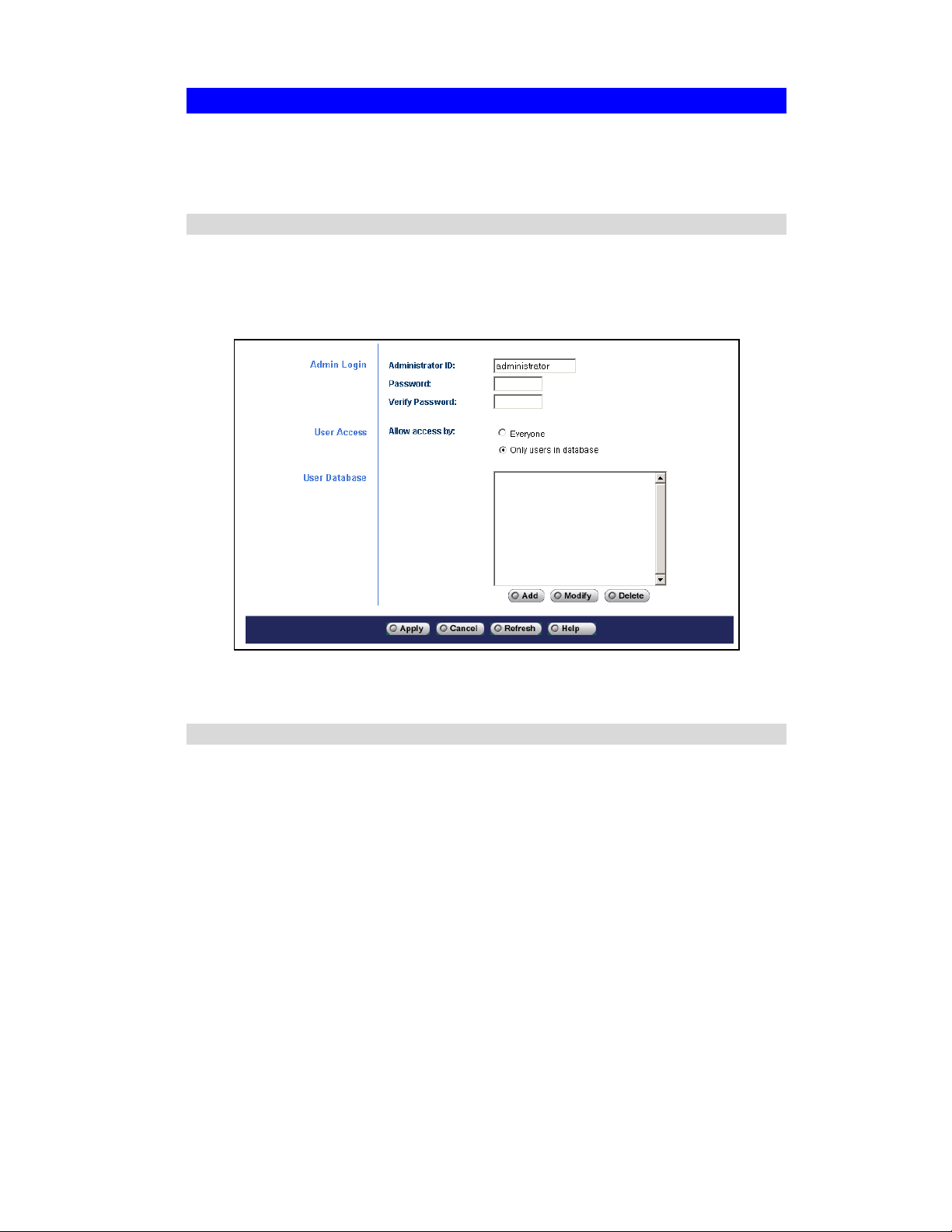
Figure 15: User Screen
4. To add users to the database, click Add and enter the name and password for each user.
Operation
• When each user connects, they will be prompted for their username and password. They
must enter the name and password defined on the User screen.
• If using the Windows Viewing/Recording utility, the username and password can be
entered so users do not need to provide the login data each time.
16
Page 21
Making Video Available From the Internet
If your LAN is connected to the Internet (typically via a broadband gateway/router and
broadband modem), you can make the Camera available on the Internet.
Wireless/Ethernet Network Camera Setup
The Camera configuration does NOT have to be changed, unless:
• You want to change the port number from its default value (1024).
• You want to use the DDNS (Dynamic DNS) feature of the Camera.
Second Port Configuration
Normally, HTTP (Web) connections use port 80. Since the Camera uses HTTP, but port 80 is
likely to be used by a Web server, you can use a different port for the Camera. This port is
called the “Second Port” (the first port being port 80).
The default second port number is 1024. If you prefer to use a different port number, you can
specify the port number in the Camera's “Network” screen, as shown below.
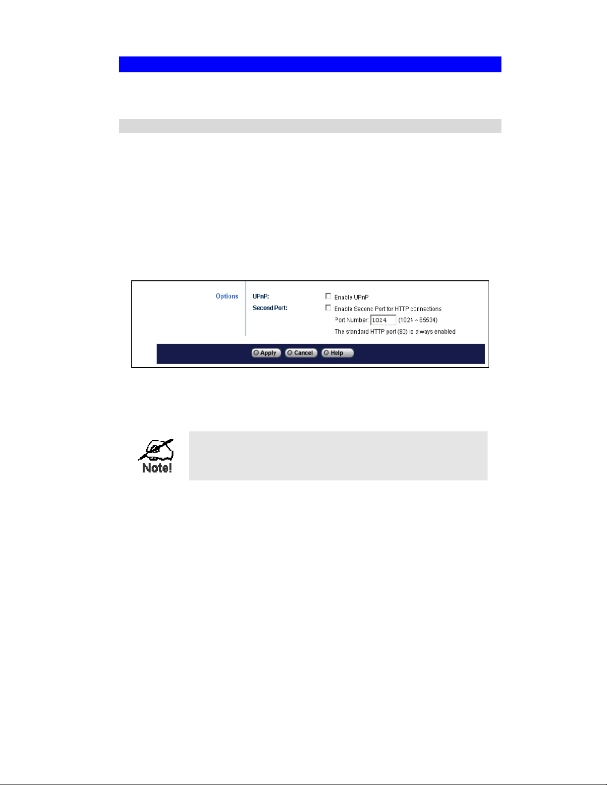
Figure 16: Network Screen
The Network screen is part of the Administration interface. See Chapter 4, “Web-based
Management,” for further details on using this interface.
Viewers need to know this port number in order to connect
and view live video, so you must inform viewers of the
current port number.
DDNS (Dynamic DNS)
Many Internet connections use a “Dynamic IP address” where the IP address is allocated
whenever the Internet connection is established.
This means other Internet users don't know the IP address, so can't establish a connection.
DDNS is designed to solve this problem by allowing users to connect to your LAN using a
domain name rather than an IP address.
To Use DDNS:
1. Register for the DDNS service with a supported DDNS service provider. You can then
apply for and be allocated a domain name.
17
Page 22

2. Enter and save the correct DDNS settings in the “Network” screen of the Camera.
Figure 17: DDNS Settings - Network Screen
3. Operation is then automatic:
• The Camera will contact the DDNS server whenever it detects a change in the Internet
IP address, and inform the DDNS server of the new address.
• Internet users can connect to your LAN using the domain name allocated by the
DDNS service provider.
Gateway/Router Setup
Your gateway/router must be configured to pass incoming TCP (HTTP) connections from
viewers to the Camera. The gateway/router uses the port number to determine which incoming
connections are intended for the Camera.
This feature is normally called “Port Forwarding” or “Virtual Servers,” and is illustrated
below. The Port Forwarding/Virtual Server entry tells the gateway/router that incoming TCP
connections on port 1024 should be passed to the Camera. If necessary, check the user manual
for your gateway/router for further details.
Figure 18: Connecting via the Internet
18
Page 23

The port for the Port Forwarding / Virtual Server entry above
is the second port number specified on the Network screen
of the Camera.
Viewing Via the Internet
Clients (viewers) will also need a broadband connection; dial-up connections are NOT
recommended.
Using the Windows Viewing/Recording Utility
If using the “Windows Viewing/Recording” utility, the details of the Camera must be entered
on the “Internet” tab of the “Add Camera” screen.
Figure 19: Add Camera from Internet
You can then select the Camera from the “Cameras” list on the main screen, and click View to
establish a connection and view live video.
See chapter 5, “Viewing and Recording,” for details about using the Windows
Viewing/Recording utility.
Using Your Web Browser
If using your Web browser, you need to know the address of the Camera (either the IP address
or the domain name) and the correct port number.
Enter the address and port number of the Camera in the “Address” (or “Location”) field of your
browser.
Example - IP address:
http://203.70.212.52:1024
where the gateway/router’s IP address is 203.70.212.52 and the second port number on
the Camera is 1024.
Example - Domain Name:
http://mycamera.dyndns.tv:1024
where the gateway/router’s domain name is “mycamera.dyndns.tv” and the second port
number on the Camera is 1024.
See chapter 5, “Viewing and Recording,” for more information about viewing video using
either the Windows Viewing/Recording utility or your Web browser.
19
Page 24

Motion Detection/E-mail Alerts
The “Motion Detection” feature will send you an e-mail when motion is detected. If desired, a
short video file can be attached to the e-mail.
The Camera will compare consecutive frames to detect changes caused by the movement of
large objects.
The motion detector can also be triggered by:
• Sudden changes in the level of available light
• Movement of the Camera itself
Try to avoid these situations. The motion detection feature works best in locations where there
is good steady illumination, and the Camera is mounted securely. It cannot be used outdoors
due to the sensitivity of the CMOS sensor.
To Use Motion Detection/E-mail Alert
Using the Web-based interface on the Camera, select the “E-mail” screen, then configure as
described below.
Figure 20: Motion Detection/E-mail Alert
To Use This Feature:
1. Activate Send E-mail Alert when Motion Detected.
2. Enter at least one (1) e-mail address
20
Page 25

3. In the “Show ‘From’ as” field, enter the e-mail address you want to display as the sender
when you receive the e-mail. This should be a genuine e-mail address, otherwise spam
filters may block your e-mail.
4. Enter a suitable “Subject” for the e-mail.
5. Enter the address of the SMTP server in the “Outgoing Mail SMTP Server” field.
If the SMTP server requires a “login” in order to send e-mail, activate My Mail Server
Requires Authentication and enter your login name and password.
6. Select the desired options
• Delay between E-mails –-used to prevent your e-mail inbox being flooded with
e-mails. Select the desired time interval.
• Motion Sensitivity - determines how readily the motion detection sensor is activated.
You can select the sensitivity, and also select the areas of the image to be examined.
Note: You must select at least one area. If you don’t, the motion detection will never
be triggered, and no e-mail alerts will ever be sent.
7. In the “Video” section, select the desired options
• Include Video - select Yes if you want to include a video with the e-mail.
• Video Length - set as desired. Note that if using higher resolution and lower
compression, even a short video file could be quite large.
8. Click Apply to save your changes.
21 22
Page 26

Chapter 4
Web-based Management
This chapter provides setup details of the Actiontec 54 Mbps Wireless
Network Camera’s Web-based interface, and should be consulted by
experienced network administrators only.
4
Introduction
The Camera can be configured using your Web browser and must have an IP address
compatible with your computer.
To do this, use the supplied Wizard, as described in the previous chapter.
Connecting to the Camera
• If you have run the Wizard, click Web UI in the Wizard’s final screen to immediately
connect to the Camera using your Web browser.
• If using only your Web browser, use the procedure below (“Connecting Using Your Web
Browser”) to establish a connection from your computer to the Camera.
• Once connected, you can add the Camera to your browser’s “Favorites” or “Bookmarks.”
Connecting Using Your Web Browser
1. Start your Web browser.
2. In the “Address” box, enter “http://” and the IP address of the Camera. In the example
below, the Camera's default IP address is used:
http://192.168.0.99
3. If the “Administrator ID” and “Password” have been assigned, you will then be prompted
for a username and password. Enter the name and password you assigned.
Page 27

Welcome Screen
When you connect, the following screen will be displayed.
Figure 21: Welcome Screen
The menu options available from this screen are:
• View Video - View live video using your Web browser
• Administration - Access the Administration menu
• Exit - Terminate the connection to the Camera
These options are explained in the following sections.
23
Page 28

View Video Screen
This screen is displayed when you click View Video.
Figure 22: View Video Screen
• You may see a prompt regarding an “OCX” file, like the example below.
You must install this OCX file in order to view the video. Click Yes.
Figure 23 OCX Prompt
• Video will start playing automatically. There may be a delay of a few seconds while the
video stream is buffered.
24
Page 29

Administration Menu
Clicking Administration on the menu provides access to all the settings for the Camera.
The “Administration” menu contains the following options:
• System – Description, Date/Time, and NTP
• Network - All network and wireless settings
• Image - Adjust the video image
• Users - Administrator login, user access, and user database
• E-mail - E-mail alerts and e-mail video
• Status - Current status information
System Screen
After clicking Administration on the main menu or selecting System from the Administration
menu, you will see a screen similar to the one below.
Data - System Screen
System Settings
Device Name
Description
Time
Date
Timezone
Displays the name of the Camera.
Used for entering a description, such as the location of the Camera.
Enter the current time.
Enter the current date.
Select the time zone for your location from the drop-down list.
If your location is currently using Daylight Savings Time, activate the
“Adjust for daylight saving” check box.
You must deactivate this check box when Standard Time is in effect.
Figure 24: System Screen
25
Page 30

NTP (Network Time Protocol)
Time Server
Server Address
Update Schedule
Enable or disable the Time Server feature as required.
If enabled, the Camera will contact a network time server at regular
intervals and update its internal timer.
Enter the address for the desired NTP server.
Determines how often the Camera contacts the NTP Server.
Select the desired options.
26
Page 31

Network Screen
This screen is displayed when the “Network” menu option is clicked.
Data - Network Screen
IP Setting
Obtain Address
Automatically
Fixed IP Address
If selected, the Camera will obtain its IP address and related
information from a DHCP server. Only select this option if your
LAN has a DHCP server.
If selected, you must assign the following data to the Camera.
• IP Address - Enter an unused IP address from the address
• Subnet Mask - Use the same value as computers on your
• Gateway - Use the same value as computers on your LAN.
• Primary DNS Address - Use the same value as computers on
• Secondary DNS Address - This is optional. If entered, this
Figure 25: Network Screen
range used on your LAN.
LAN.
your LAN. Normally, your ISP will provide this address.
DNS will be used if the primary DNS does not respond.
27
Page 32

Wireless Setting
Mode
Authentication Type
ESSID
Domain
Channel No.
WEP
Determines the type of wireless communication used by the
Camera.
• If you have an access point, select Infrastructure.
• Otherwise, select Ad-hoc.
Select the appropriate value (Open System or Shared Key), as
used on your LAN.
Note: In Infrastructure mode, either setting will normally work,
since most access points can use both methods.
This must match the value used by other devices on your wireless
LAN.
Note: The SSID is case sensitive.
Select your region from the drop-down list.
• In Infrastructure mode, this setting is ignored. The Camera will
use the channel set on the access point.
• For Ad-hoc mode, select the channel you wish to use on your
Camera. Other wireless stations should use the same setting.
• If you experience interference (shown by lost connections
and/or slow data transfers), you may need to experiment with
different channels to see which one is the best.
This shows the current WEP setting.
• This must match other wireless stations on your LAN.
• Click Configure WEP to change the WEP settings if required.
DDNS
DDNS
Enable/Disable
Service Provider
Host Name
Account
Password
Check WAN IP
Schedule
Options
UPnP
Enable or disable the DDNS function, as required.
Only enable this feature if you have registered for the DDNS
service with a DDNS server provider.
Choose a service provider from the list.
Enter the host name (domain name) allocated to you by the DDNS
server provider.
Enter the login name for the DDNS account.
Enter the password for the DDNS account.
Set the schedule for checking if the IP address has changed. If the
IP address has changed, the DDNS server will be notified.
Enable UPnP support if required. If enabled, the Camera will
broadcast its availability using UPnP. UPnP compatible systems
such as Windows XP will then be able to detect the presence of the
Camera.
28
Page 33

Second Port
Enable this feature if required. If enabled, then HTTP connections
(using your Web browser or media player) can use this port number
instead of the standard HTTP port 80.
• If you already have a Web server on your LAN, then you
should enable the second port, and use this port number instead
of port 80.
• If enabled, enter the desired port number to use for connections
to the Camera. The default is 1024.
Using DDNS (Dynamic DNS)
Many Internet connections use a “Dynamic IP address,” where the IP address is allocated
whenever the Internet connection is established.
This means that other Internet users don't know the IP address, and can't establish a connection.
DDNS is designed to solve this problem, as follows:
• You must register for the DDNS service with a DDNS service provider. The DDNS
service provider will allocate a domain name to you upon request.
• The DDNS settings on the Network screen must be correct.
• The Camera will then contact the DDNS server whenever it detects that the IP address has
changed, and inform the DDNS server of the new IP address. (“Check WAN IP Schedule”
determines how often the Camera checks if the IP address has changed.)
This system allows other Internet users to connect to you using the domain name allocated by
the DDNS service provider.
29
Page 34

WEP Screen
This screen is accessed by clicking Configure on the Network screen and selecting WEP from
the “Security System” menu. An example WEP screen is shown below.
Figure 26: WEP Screen
Data - WEP Screen
WEP Encryption
WEP Encryption
Passphrase
Default Key
Key Value
Select the option used on your wireless LAN.
• None - This is the default. If selected, data is not encrypted before
being transmitted.
• 64 Bit Encryption - If selected, data is encrypted, using the
default key, before being transmitted.
You must enter a default key.
Other wireless stations must be set to use 64-bit encryption, and
have the same Key value in the same position in their key table.
• 128 Bit Encryption - If selected, data is encrypted, using the
default key, before being transmitted.
You must enter a default key.
Other wireless stations must be set to use 128-bit encryption, and
have the same Key value in the same position in their key table.
Generates a key from the phrase you enter, which may be easier than
entering keys in hexadecimal format (0~9 and A~F).
To use the Passphrase feature, enter the desired passphrase in the field
provided, then click Generate.
Select a key to be used as the default key.
If WEP encryption is used, you must enter at least one key value, the
“Default Key.” All transmissions are encrypted using the Default Key.
Other wireless stations must use the same key value in the same
position in their key table (it does not have to be selected as the default
key).
The other key values are optional, and are used only for decrypting
data. This allows you to use different keys for transmitting and
receiving, if required.
30
Page 35

When inputting a key value, follow these rules:
• For 64-bit encryption, keys must be 10 characters.
• For 128-bit encryption, keys must be 26 characters.
• Keys must be entered in hexadecimal format.
Hexadecimal characters are A - F and 0 - 9.
31
Page 36

WPA-PSK Screen
This screen is accessed by clicking Configure on the Network screen and selecting WPA-PSK
from the “Security System” menu. An example WPA-PSK screen is shown below.
Figure 27: WPA-PSK Screen
Data – WPA-PSK Screen
WEP Encryption
WPA-PSK
Encryption
WPA Shared
Key
Select the option used on your wireless LAN.
• TKIP- Stands for “Temporal Key Integrity Protocol” and is a
security protocol for wireless networks. This is the default setting,
and the only one currently available.
Enter a case-sensitive alphanumeric key (from 8 to 63 characters in
length) here. If the Camera is connected to an access point or
gateway/router, enter the same pre-shared key as the device.
Image Screen
This screen is displayed by clicking Image.
Figure 28: Image Screen
32
Page 37

Data - Image Screen
Video Settings
Resolution
Image Quality
Power line
frequency
Adjustment
Brightness
Red, Green, Blue
Default
Button
Options
Time Stamp
Text Display
Select the desired video resolution format. The default resolution is
set to 320*240.
Select the desired image quality. Default is set to “Normal.”
Note: Higher image quality requires more bandwidth.
Select the power line frequency (50Hz or 60Hz) used in your region,
to improve the picture quality under florescent lighting.
The default is “Automatic.” At this setting, the Camera will
automatically adjust the brightness based on the current
environment. If you want to adjust the brightness manually, click
Manual.
Adjust these color settings to the preferred values.
Note: When Automatic is selected, these settings will not take
effect.
Clicking this button will set all the Adjustment fields to their default
values. Click Apply to save these changes.
Activate to display the time on the video image.
Activate to display text on the video image. You can enter up to 20
characters. This feature is often used to identify a Camera when
multiple Cameras are installed.
Audio
Activate to include audio with the video image. Some bandwidth
will be allocated to the audio stream. In some situations, this may
affect the quality of the video.
Note: Audio is only available with MPEG-4 video.
33
Page 38

User Screen
This screen is displayed after clicking User.
Figure 29: User Screen
Data - User Screen
Admin Login
Administrator ID
Password
Verify Password
User Access
Allow access by
User Database
User List
Buttons
• Enter the name of the administrator here. Do not use spaces,
punctuation, and special characters in the administrator name.
• The name is case insensitive (case is ignored), so you cannot
have two names differentiated by case only.
Enter the Administrator’s password here.
Re-enter the Administrator password here.
• Everyone - Anyone can view the video stream.
• Only users in database - Allow viewing only by people in the
user database. If selected, users will be prompted for a user
name and password when they attempt to view the video.
This displays all users you have entered into the user database. If
you have not entered any users, this list will be empty.
Use Add, Delete, and Modify to manage the user database.
34
Page 39

Add/Modify User Screen
This screen is displayed after clicking Add or Modify from the User screen. It is used to enter
details of each user.
Figure 30: Add/Modify User Screen
Data - Add/Modify User
User Name
User Password
Confirm Password
Enter the name of the user. Do not use spaces, punctuation, and
special characters in the name.
Also, names are case-insensitive (case is ignored), so you cannot use
two names with the same spelling, but different cases.
Enter the user’s password.
Re-enter the user’s password.
35
Page 40

E-mail Screen
If desired, you can use the E-mail feature to have an e-mail sent to you whenever motion is
detected. Because of the sensitivity of the CMOS digitizer, the motion detection feature is not
usable in situations where the level of illumination changes rapidly. In this situation, the
change in light intensity will trigger the motion detection.
.
Data – E-mail Screen
E-Mail Alerts
Enable
E-mail Address
Show “From” as
Subject
Activate to enable the E-Mail Alert feature. E-mails are sent when
motion is detected.
Note: Motion detection can be triggered by rapid changes in lighting
conditions, as well as by moving objects. For this reason, it should only
be used indoors.
Enter at least one e-mail address; the second and third addresses are
optional. The e-mail alert will be sent to the e-mail address or
addresses specified here.
Enter the e-mail address to be shown in the “From” field when the
e-mail is received.
Enter the e-mail subject line here. Subject cannot exceed 48
alphanumeric characters.
Figure 31: E-mail Screen
36
Page 41

Outgoing Mail
SMTP Server
Delay between
E-mails
Motion Detection
E-mail Video
Include Video
Video Length
Enter the address of the SMTP (Simple Mail Transport Protocol) server
to be used to send e-mail.
If the SMTP server requires a "login" to send mail, activate My Mail
Server Requires Authentication and enter your login name and
password for the SMTP server. (This is usually the same as the POP3
server used to receive e-mail.)
Use this to ensure your e-mail inbox is not flooded with e-mail alerts.
Select the desired time delay between e-mail alerts.
• Sensitivity - Select the desired option to suit your environment. If
covering a large area, you will need higher sensitivity, since a
moving object will take up only a small portion of the image.
• Areas of the image to be examined - Use the checkboxes to
determine which areas of the image will be examined for motion.
You can also use “Select All” and “Select None” if desired.
Select Yes to include a short video in your e-mail alert.
Select the desired length. The size of the file depends on this setting,
along with the video size and degree of compression.
37
Page 42

Status Screen
.
Figure 32: Status Screen
Data - Status Screen
System
Device Name
Description
F/W version
Network
MAC Address
IP Address
Network Mask
Gateway
Wireless (Wireless Camera Only)
Network Type
Displays the name of the Camera.
Displays the description of the Camera.
Displays the version of the firmware installed.
You can upgrade the firmware by clicking Upgrade Firmware. You
need to obtain the firmware upgrade file first.
Displays the current IP address of the Camera.
Displays the IP address of the Camera.
Displays the network mask associated with the IP address.
Displays the IP address of the remote gateway associated with the IP
address.
Displays the network type currently in use (Ad-hoc or
Infrastructure).
SSID
Channel
Encryption
Displays the wireless SSID.
Displays the wireless channel currently used.
Indicates if WEP data encryption is being used. If it is, indicates the
key size (64- or 128-bit).
38
Page 43

Video
Resolution
Current Viewers
Log
Log Data
Buttons
Refresh
Restart
Restore Factory
Defaults
Displays the image size of the video stream.
Displays how many viewers are currently viewing the video stream.
Displays the log records of various system activities
Updates the log and any other data on screen.
Restarts the Camera.
Note: This will break any existing connections. Anyone watching or
recording live video will be disconnected.
Use this to restore all settings to their factory default values.
• Anyone watching or recording live video will lose the connection.
• If you previously changed the IP address of the Camera from its
default value, this operation will change the IP address back to the
default value.
If the IP address changes, you will have to use the default IP
address to re-connect.
• The default IP address is 192.168.0.99
39
Page 44

Upgrade Firmware Screen
This screen is displayed when you click Upgrade Firmware on the Status screen.
Figure 33: Upgrade Firmware Screen
This screen allows you upgrade the Camera’s firmware. Before using this screen, you must
download the upgrade file to your computer.
After downloading the upgrade file:
1. Click Browse, and locate the upgrade file.
2. Select the file, then click OK. The filename appears in the “Upgrade File” field.
3. Click Start Upgrade to transfer the file to the Camera and start the upgrade procedure.
Note:
• The “Cancel” button cannot cancel an upgrade once it has started.
• The upgrade may take several minutes.
• When the upgrade is complete, the Camera restarts. This will cause any existing
connections to be terminated, and any users viewing or recording video will see an error.
40 41
Page 45

Chapter 5
Viewing & Recording
This chapter describes how to view and record the live video stream
generated by the Actiontec 54 Mbps Wireless Network Camera.
Overview
The recommended method to view video is to use the “Windows Viewing/Recording” utility.
Installation
1. Insert the supplied CD into your CD-ROM drive. If the “Setup” program does not start
automatically, run Setup.exe in the root folder. The “Welcome” screen appears.
5
Figure 34: Welcome Screen
2. Click Client Utility to start the installation of the Viewing/Recording utility.
3. Follow the prompts to complete the installation.
Page 46

System Tray Icon
When started, the utility creates an icon in the system tray on the taskbar next to the clock.
Figure 35: System Tray Icon
This icon has the following functions:
• Animation - If a recording is in progress, this icon animates. Otherwise, it is stationary.
• Hover - Hovering your mouse over this icon will generate a pop-up informing you of the
current status.
• Double-click - This will display the main screen, shown below.
• Right-click - This provides a menu that allows you to view program details, view the main
screen, or terminate the utility.
Main Screen
When the utility starts, the “Main” screen appears.
Figure 36: Main Screen
42
Page 47

Cameras - Camera List
• The “Camera List” displays all Cameras you have defined. If you have not defined any
Cameras, this list will be empty. For each listed Camera, the following data is shown:
• Device Name - The name of the Camera.
• Connection Type - This displays either “LAN” or “Internet,” indicating the type of
connection used to connect to the Camera.
• Description - If the Camera administrator has entered a description, it will be
displayed here.
• Status - Normally, this will be blank. If a connection error occurs, it is indicated here.
• Click Add Camera to add a Camera. See the following section for further details.
• Once Cameras are listed, select one to use the Modify Camera, Delete Camera, and
View buttons.
• To view live video, select a Camera and click View.
Recordings - Current Recordings
This panel lists all scheduled recordings currently in progress.
Any recording in progress can be terminated by selecting it and clicking Stop.
43
Page 48

Adding Cameras to the Camera List
To add a camera to the Camera List, click Add Camera on the main screen. You will see a
screen like the example below.
• Cameras on LAN - displays all Cameras found on your LAN. This list can be updated by
clicking Refresh.
• Camera Data - displays the data for the selected Camera.
Figure 37: Add Camera from LAN
To add a Camera to the Camera List on the main screen:
1. Select a Camera from the list on the left.
2. Check that the “Camera Data” on the right side of the screen is correct. See below for
details.
3. Click Add. The Camera will now appear in the Camera List on the main screen.
Camera Data - LAN
Device Name Displays the default name of the Camera, and cannot be changed.
Description Displays the description entered by the Camera administrator.
Address Displays the current IP address of the Camera.
Port Number
Login
This will normally display “80.” Only change this if requested to do so
by the Camera administrator.
The Camera administrator can require that users provide a username and
password before being allowed to view the live video.
• If the administrator has not enabled this option, the “Login” fields
can be left blank.
• Otherwise, you must enter the username and password allocated to
you by the administrator.
You can add the same Camera twice, once for the LAN (using
the LAN IP address), and again for the Internet (using the
Internet IP address). This will allow viewing the Camera whether
you are on the same LAN as the Camera or in a remote location.
44
Page 49

Adding Cameras on the Internet
If the Camera you want to add is not on your LAN, but is available via the Internet, click
Internet. You will see a screen similar to the one below.
Figure 38: Add Camera from Internet
To add a camera to the “Camera List” on the Main screen:
1. Enter the “Camera Data” in the panel on the right. See below for details.
2. Click Test to check that a connection and login can be performed successfully.
3. Click Add. The Camera will now appear in the “Camera List” on the Main screen.
Camera Data - Internet
Device Name
Description
Address
Port Number
Login
Displays the default name of the Camera, and cannot be changed.
This field will be displayed automatically once a connection to the
Camera has been established.
Displays the description entered by the Camera administrator.
This field will be displayed automatically once a connection to the
Camera has been established.
Enter the domain name or IP address of the Camera.
Enter the port number used by the Camera. The Camera administrator
can advise which port to use. The default value is 1024.
The Camera administrator can require that users provide a username and
password before being allowed to view the live video.
• If the administrator has not enabled this option, the “Login” fields
can be left blank.
• Otherwise, you must enter the username and password allocated to
your by the administrator.
You can add the same Camera twice, once for the LAN, and
again for the Internet. This will allow viewing the Camera
whether you are on the same LAN as the Camera or in a remote
location.
45
Page 50

Modifying an Existing Camera
You can change the settings for an existing Camera by selecting it in the “Camera List” on the
Main screen, then clicking Modify Camera.
You will see a screen similar to the one below.
Figure 39: Modify Camera
• Data on this screen is the same as for the Add Camera screens.
• Click Test to check that a connection and login can be performed successfully.
46
Page 51

Viewing Live Video
To view live video, select a Camera in the “Camera List” on the Main screen, and click View.
For each camera, a new viewing window will open similar to the one below.
Figure 40: Viewing Live Video
Controls are provided to stop and start viewing, and to start recording the video stream.
Play - Use this to re-start viewing (after clicking Stop).
Record. - Click to start recording the current video stream.
While recording, this button will be red. To stop recording, click the button
again.
Stop. - This will terminate the connection to the Camera, halting both the
viewing and the recording (if in progress).
Snapshot - Click to take a single JPEG “snapshot” image of the current video.
You can use “Preferences” to set the folder where these images are stored.
Audio. This can be used to select the audio stream. (Only one audio stream can
be selected at any time.) If the Camera does not support audio, or if audio is
disabled on the Camera, this option is unavailable, and a red “X” will cover the
icon.
2X - Clicking this will set the viewing image to double size. The icon will then
change to the “1X” icon below.
1X - Clicking this will set the viewing image to standard size. The icon will then
change to the “2X” icon above.
47
Page 52

Recording Video
You can record video while watching, or schedule recordings to occur when you are absent.
Recordings are stored in a standard Microsoft ASF file format, and can be played using
Microsoft Media Player.
Before recording, you should review the “Recording Preferences” to ensure they are suitable
for your computer.
Recording Preferences
To set the Camera’s recording preferences, click Preferences below the “Recordings” panel on
the Main screen. You will see a screen similar to the one below.
Figure 41: Recording Preferences
If necessary, change these settings to suit your environment.
Record File
Location
Snapshot File
Location
Time Limit
Displays the drive and folder on your computer where recorded files will
be placed. To store the videos, you need a drive with large amounts of
free space. Click Browse to select the drive and folder.
Note: File names are automatically assigned, using the date and time.
Displays the location where snapshot images (still images, in JPEG
format) will be stored. Click Browse button to select the desired drive
and folder
Sets the maximum time of a recording.
If the recording is not stopped manually, it will be terminated after the
time period indicated here.
48
Page 53

Live Recordings
You can start and stop recording from the View screen, using the controls provided.
Figure 42: Viewing Live Video
Controls are provided to stop and start viewing, and to start recording the video stream.
Play - Use this to re-start viewing (after clicking Stop).
Record. - Click to start recording the current video stream.
While recording, this button will be red. To stop recording, click the button
again.
Stop. - This will terminate the connection to the Camera, halting both the
viewing and the recording (if in progress).
Snapshot - Click to take a single JPEG snapshot image of the current video.
You can use “Preferences” to set the folder where these images are stored.
Audio. This can be used to select the audio stream. (Only one audio stream can
be selected at any time.) If the Camera does not support audio, or if audio is
disabled on the camera, this option is unavailable, and a red “X” will cover the
icon.
2X - Clicking this will set the viewing image to double size. The icon will then
change to the “1X” icon below.
1X - Clicking this will set the viewing image to standard size. The icon will then
change to the “2X” icon above.
49
Page 54

Files
To view recorded video or snapshot (still image) pictures, click Files under the “Files” panel
on the Main screen, then select the desired option.
Figure 43: Files Screen
To view a list of all recorded files, click Recorded Video, and you will see a screen similar to
the one below.
Figure 44: Recorded Files
This list shows all of the recorded files. The following operations are supported:
• Play - Play the selected file using Microsoft Media Player.
• Delete - Delete the selected file.
• Explore - Open the folder containing these files, using Windows Explorer.
50
Page 55

Scheduled Recordings
Recordings can be scheduled at any time, for any known Camera (your computer must be
powered up at the scheduled time).
To use this feature, click Schedule under the “Recordings” panel on the Main screen. You will
see a screen similar to the one below.
Figure 45: Scheduled Recording List
This screen lists all scheduled recordings. For each recording, the following data is shown:
• Camera - Displays the recording Camera.
• Date - Displays the date the recording will be made. If the recording schedule is repetitive,
this is the date of the next recording.
• Time - Displays the time the recording will be made.
• Type - Indicates if the recording is “One Time,” “Everyday,” or on a particular day each
week.
If a scheduled recording is selected, Modify and Delete can be used to edit or delete the
selected entry.
51
Page 56

Schedule Definition Screen
If Add or Modify is clicked, a screen similar to the one below appears. You can then enter or
modify the details of this schedule.
Figure 46: Schedule Definition Screen
Data - Schedule Definition
Camera
Schedule Type
Start Day
Start Time
Duration
Select the Camera to be used. If the desired Camera is not listed, you
must define it by clicking Add Camera on the Main screen.
Select the desired option:
• One Time - Only one recording is made, at the specified date and
time.
• Everyday - The recording is made every day at the specified time.
The “Start Day” indicates when the first recording will be made.
• Every Sunday, Every Monday - The recording is made on the
specified day each week. The “Start Day” (see below) indicates
when the schedule becomes active.
Select the desired date, according to your needs:
• For a single recording, the day the recording will be made.
• For daily (Everyday) recordings, the starting date.
• For weekly recordings, when the schedule becomes active.
Select the start time.
Enter or select the duration of the recording.
52
Page 57

Viewing With Your Web Browser
The recommended method to view live video from the Camera is to use the Windows utility.
However, you can also use your Web browser, if necessary.
Viewing Over Your LAN
To establish a connection from your computer to the Camera:
1. Start your Web browser.
2. In the Address text box of the browser, enter the IP address of the Camera. In the example
below, the Camera’s default IP address is used:
http://192.168.0.99
3. If the administrator enabled the user security feature, you will then be prompted for a
username and password. Enter the username and password
4. When you connect, the following screen appears.
Figure 47: Home Screen
53
Page 58

5. Click View Video, and a screen similar to the one below appears.
Figure 48: View Video Screen
• If using Internet Explorer on Windows, you may see a prompt regarding an “OCX” file, as
shown below.
You must install this file in order to view the video. Click Yes.
Figure 49: OCX Prompt
• Video will start playing automatically. There may be a delay of a few seconds while the
video stream is buffered.
54
Page 59

Viewing Via the Internet
If the LAN with the Camera is connected to the Internet and configured correctly, you can
connect to the Camera via the Internet.
See “Making Video Available From the Internet” in chapter 3 for details about the required
LAN configuration.
To establish a connection from your computer to the Camera via the Internet:
1. Obtain the Internet address and port number of the Camera from the administrator.
2. Start your Web browser.
In the Address text box, enter the IP address of the camera
Example:
http://203.70.212.52:1024
In the example, the gateway/router’s IP address is 203.70.212.52 and the second port
number of the Camera is 1024.
Alternatively, you can enter a domain name, if applicable:
Example:
http://mycamera.dyndns.tv:1024
In this example, the gateway/router’s domain name is mycamera.dyndns.tv and the
second port number of the Camera is 1024.
3. If the administrator has enabled the user validation feature, you will then be prompted for
a username and password.
Enter the name and password.
4. When you connect, the following screen appears.
Figure 50: Home Screen
55
Page 60

5. Click View Video and a screen similar to the one below appears.
Figure 51: View Video Screen
• If using Internet Explorer on Windows, you may see a prompt regarding an “OCX” file,
similar to the one below.
You must install this OCX file in order to view the video. Click Yes.
Figure 52: OCX Prompt
• Video will start playing automatically. There may be a delay of a few seconds while the
video stream is buffered.
Note: Viewers need a broadband Internet connection to view video effectively. Dial-up
connections are not recommended.
56
Page 61

Chapter 6
Troubleshooting
6
This chapter covers problems the user may encounter while using the
Actiontec 54 Mbps Wireless Network Camera, and possible solutions.
Overview
This chapter covers some common problems users may encounter using the Camera, and some
possible solutions to them. If you follow the suggested steps and the Camera still does not
function properly, contact your dealer for further advice.
Problems
Problem 1: I can't connect to the Camera with my Web browser to configure it.
Solution 1:
Problem 2: The Windows utility doesn't list any Cameras.
Solution 2: Check the following:
Problem 3 When I try to connect to the Camera, I get prompted for a user name and
It is possible that your computer’s IP address is not compatible with the IP
address of the Camera.
Use the Windows utility to configure the Camera with a valid IP address.
• The Camera is installed, LAN connections are OK, it is powered on and
startup is complete.
• Ensure that your computer and the camera are on the same network
segment. (If you don't have a gateway/router, this must be the case.)
• Ensure that your computer has the TCP/IP network protocol loaded. In
Windows, click Network in the Control Panel. If an entry for TCP/IP -
Network card is not listed, select Add - Protocol - Microsoft - TCP/IP to
add it.
You then need to select the new entry (TCP/IP - Network card), click
Properties, and configure the “IP Address” tab.
• If your LAN has a DHCP server, you can select Obtain an IP
Address automatically.
• Otherwise, you must select Specify an IP Address, and enter values
for “IP Address,” “Subnet Mask,” and “Gateway.” All devices on your
LAN must use compatible values. Remember that each device needs a
unique IP address, and the same subnet mask.
password.
Solution 3 You should be prompted for a user name and password if trying to access the
Administration menu.
Enter the “Administrator ID” and “Password” set on the User screen.
If you are just trying to view video, the User Name/Password prompt indicates
the administrator has restricted access to specified users. Ask the administrator
for your user name and password.
57
Page 62

Problem 4 I can't connect to the Camera using a wireless connection.
Solution 4 1) If a LAN cable is connected to the LAN port, the wireless interface is
disabled. Only one interface can be active.
2) Check that your computer and the Camera have compatible wireless settings.
• Mode (Infrastructure or Ad-hoc) must be correct
• ESSID must match
• WEP settings must match
• In Ad-hoc mode, the channel should match, although this is often not
required
Problem 5 My video quality suddenly deteriorates.
Solution 5 This can happen when an additional viewer connects to the Camera,
overloading it or the available bandwidth. The image size and quality can be
adjusted for the required number of viewers and the available bandwidth.
Problem 6 The motion detection feature doesn't send me any e-mails.
Solution 6 It may be that the SMTP server used by the Camera to send the e-mail will not
accept mail from the Camera. Try using a different SMTP server. The Camera
derives the address of the SMTP server from the e-mail address you enter in the
“Show ‘From’ as:” field.
Problem 7 Using the motion detection feature, I receive e-mails that don't show any
moving objects.
Solution 7 The motion detection feature doesn't actually detect motion. It compares frames
to see if they are different. Major differences between frames are assumed to be
caused by moving objects.
But the motion detector can also be triggered by:
• Sudden changes in the level of available light
• Movement of the Camera itself
Try to avoid these situations. The motion detection feature works best in
locations where there is steady illumination, and the Camera is mounted
securely. This feature cannot be used if the Camera is outdoors.
Problem 8 The image is blurry.
Solution 8 Try cleaning the lens, and adjusting the focus ring.
58
Page 63

Appendix A Specifications
A
Actiontec 54 Mbps Wireless Network Camera
Model Actiontec 54 Mbps Wireless Network Camera
Resolution Support 640x480, 320x240, 160x120 (color)
Image Alteration Brightness, Color (red, green,blue)
Video Options Motion-detection, time stamp, text overlay
Microphone Built-in microphone and microphone jack for external microphone
Audio Options On/Off control on Web interface, Windows playback
Standards
Range Indoor: approximately 150 ft. (maximum, open site)
Encryption WEP 64-, 128-bit
LAN 10/100BaseT Ethernet
LED Indicators Ready, Active, LAN, Wireless
Size 3.3 x 5.9 x 1.3 inches
Weight 0.49 lbs
Compliant with IEEE 802.11b, 802.11g compatible,
(Infrastructure/Ad-hoc mode)
Certification FCC, CE
Limited Warranty 1 year
59
Page 64

Regulatory Approvals
CE Approvals
The Actiontec 54 Mbps Wireless Network Camera meets the guidelines of the European Union
and complies with the 99/5/EEC and RTTE 99/5EG directives, including the following
standards:
• EN60950
• EN300 328-2
• EN301 489-1
• EN301 489-17
This is a Class B product. In a domestic environment this product may cause radio interference
in which case the user may be required to take adequate measures.
60
Page 65

Limited Warranty
HARDWARE: Actiontec Electronics Inc. warrants to the end user
(“Customer”) that this hardware product will be free from defects in
workmanship and materials, under normal use and service, for twelve (12)
months from the date of purchase from Actiontec Electronics or its authorized
reseller.
Actiontec Electronics’ sole obligation under this express warranty shall be, at
Actiontec’s option and expense, to repair the defective product or part, deliver
to Customer an equivalent product or part to replace the defective item, or if
neither of the two foregoing options is reasonably available, Actiontec
Electronics may, in its sole discretion, refund to Customer the purchase price
paid for the defective product. All products that are replaced will become the
property of Actiontec Electronics Inc. Replacement products may be new or
reconditioned. Actiontec Electronics warrants any replaced or repaired product
or part for ninety (90) days from shipment, or the remainder of the initial
warranty period, whichever is longer.
SOFTWARE: Actiontec Electronics warrants to Customer that each software
program licensed from it will perform in substantial conformance to its
program specifications, for a period of ninety (90) days from the date of
purchase from Actiontec Electronics or its authorized reseller. Actiontec
Electronics warrants the media containing software against failure during the
warranty period. The only updates that will be provided are at the sole
discretion of Actiontec Electronics and will only be available for download at
the Actiontec website, www.actiontec.com. Actiontec Electronics’ sole
obligation under this express warranty shall be, at Actiontec Electronics’
option and expense, to replace any defective media with software which
substantially conforms to applicable Actiontec Electronics’ published
specifications. Customer assumes responsibility for the selection of the
appropriate applications program and associated reference materials. Actiontec
Electronics makes no warranty or representation that its software products will
meet Customer’s requirements or work in combination with any hardware or
applications software products provided by third parties, that the operation of
the software products will be uninterrupted or error free, or that all defects in
the software products will be corrected. For any third-party products listed in
the Actiontec Electronics software product documentation or specifications as
being compatible, Actiontec Electronics will make reasonable efforts to
provide compatibility, except where the non-compatibility is caused by a “bug”
or defect in the third party’s product or from use of the software product not in
accordance with Actiontec Electronics published specifications or User Guide.
THIS ACTIONTEC ELECTRONICS PRODUCT MAY INCLUDE OR BE
BUNDLED WITH THIRD-PARTY SOFTWARE, THE USE OF WHICH IS
GOVERNED BY A SEPARATE END-USER LICENSE AGREEMENT.
THIS ACTIONTEC ELECTRONICS WARRANTY DOES NOT APPLY TO
SUCH THIRD-PARTY SOFTWARE. FOR THE APPLICABLE
61
Page 66

WARRANTY, PLEASE REFER TO THE END-USER LICENSE
AGREEMENT GOVERNING THE USE OF SUCH SOFTWARE
OBTAINING WARRANTY SERVICE: Customer may contact Actiontec
Electronics Technical Support Center within the applicable warranty period to
obtain warranty service authorization. Dated proof of purchase from Actiontec
Electronics or its authorized reseller may be required. Products returned to
Actiontec Electronics must be pre-authorized by Actiontec Electronics with a
Return Merchandise Authorization (RMA) number marked on the outside of
the package, and sent prepaid and packaged appropriately for safe shipment,
and it is recommended that they be insured or sent by a method that provides
for tracking of the package. The repaired or replaced item will be shipped to
Customer, at Actiontec Electronics’ expense, not later than thirty (30) days
after Actiontec Electronics receives the defective product. Return the product
to:
In the United States
Actiontec Electronics, Inc
760 North Mary Avenue
Sunnyvale, CA 94085
Actiontec Electronics shall not be responsible for any software, firmware,
information or memory data or Customer contained in, stored on, or integrated
with any products returned to Actiontec Electronics for repair, whether under
warranty or not.
WARRANTIES EXCLUSIVE: IF AN ACTIONTEC ELECTRONICS’
PRODUCT DOES NOT OPERATE AS WARRANTED ABOVE,
CUSTOMER’S SOLE REMEDY FOR BREACH OF THAT WARRANTY
SHALL BE REPAIR, REPLACEMENT, OR REFUND OF THE PURCHASE
PRICE PAID, AT ACTIONTEC ELECTRONICS’ OPTION. TO THE FULL
EXTENT ALLOWED BY LAW, THE FOREGOING WARRANTIES AND
REMEDIES ARE EXCLUSIVE AND IN LIEU OF ALL OTHER
WARRANTIES, TERMS OR CONDITIONS, EXPRESS OR IMPLIED,
EITHER IN FACT OR BY OPERATION OF LAW, STATUTORY OR
OTHERWISE, INCLUDING WARRANTIES, TERMS OR CONDITIONS
OF MERCHANTABILITY, FITNESS FOR A PARTICULAR PURPOSE,
SATISFACTORY QUALITY, CORRESPONDENCE WITH DESCRIPTION,
AND NON-INFRINGEMENT, ALL OF WHICH ARE EXPRESSLY
DISCLAIMED. ACTIONTEC ELECTRONICS NEITHER ASSUMES NOR
AUTHORIZES ANY OTHER PERSON TO ASSUME FOR IT ANY OTHER
LIABILITY IN CONNECTION WITH THE SALE, INSTALLATION,
MAINTENANCE OR USE OF ITS PRODUCTS.
ACTIONTEC ELECTRONCS SHALL NOT BE LIABLE UNDER THIS
WARRANTY IF ITS TESTING AND EXAMINATION DISCLOSE THAT
THE ALLEGED DEFECT OR MALFUNTION IN THE PRODUCT DOES
NOT EXIST OR WAS CAUSED BY CUSTOMER’S OR ANY THIRD
PERSON’S MISUSE, NEGLECT, IMPROPER INSTALLATION OR
TESTING, UNAUTHORIZED ATTEMPT TO OPEN, REPAIR OR MODIFY
62
Page 67

THE PRODUCT, OR ANY OTHER CAUSE BEYOND THE RANGE OF
THE INTENDED USE, OR BY ACCIDENT, FIRE, LIGHTNING, OTHER
HAZARDS OR ACTS OF GOD.
LIMITATION OF LIABILITY: TO THE FULL EXTENT ALLOWED BY
LAW, ACTIONTEC ELECTRONICS ALSO EXCLUDES FOR ITSELF
AND ITS SUPPLIERS ANY LIABILITY, WHETHER BASED IN
CONTRACT OR TORT (INCLUDING NEGLIGENCE), FOR
INCIDENTAL, CONSEQUENTIAL, INDIRECT, SPECIAL, OR PUNITIVE
DAMAGES OF ANY KIND, OR FOR LOSS OF REVENUE OR PROFITS,
LOSS OF BUSINESS, LOSS OF INFORMATION OR DATA, OR OTHER
FINANCIAL LOSS ARISING OUT OF OR IN CONNECTION WITH THE
SALE, INSTALLATION, MAINTENANCE, USE, PERFORMANCE,
FAILURE, OR INTERRUPTION OF ITS PRODUCT, EVEN IF
ACTIONTEC ELECTRONICS OR ITS AUTHORIZED RESELLER HAS
BEEN ADVISED OF THE POSSIBILITY OF SUCH DAMAGES, AND
LIMITS ITS LIABILITY TO REPAIR, REPLACEMENT,OR REFUND OF
THE PURCHASE PRICE PAID, AT ACTIONTEC ELECTRONICS’
OPTION. THIS DISCLAIMER OF LIABILITY FOR DAMAGES WILL
NOT BE AFFECTED IF ANY REMEDY PROVIDED HEREIN SHALL
FAIL OF ITS ESSENTIAL PURPOSE.
DISLAIMER: Some countries, states or provinces do not allow the exclusion
or limitation of implied warranties or the limitation of incidental or
consequential damages for certain products supplied to consumers, or the
limitation of liability for personal injury, so the above limitations and
exclusions may be limited in their application to you. When the implied
warranties are not allowed to be excluded in their entirety, they will be limited
to the duration of the applicable written warranty. This warranty gives you
specific legal rights which may vary depending on local law.
DISPUTE RESOLUTION: The customer may contact the Director of
Technical Support in the event the Customer is not satisfied with Actiontec
Electronics response to the complaint. In the event that the Customer is still not
satisfied with the response of the Director of Technical Support, the Customer
is instructed to contact the Director of Marketing. In the event that the
Customer is still not satisfied with the response of the Director of Marketing,
the Customer is instructed to contact the Chief Financial Officer and/or
President.
GOVERNING LAW: This Limited Warranty shall be governed by the laws
of the State of California, U.S.A. excluding its conflicts of laws principles and
excluding the United Nations Convention on Contracts for the International
Sale of Goods.
63
 Loading...