

Page 1

T- B E R D
®
950
User’s Guide
November 2000
Formerly TTC and WWG
20400 Observation Drive, Germantown, Maryland 20876 -4023 USA
USA 1-800-638-2049 • +1-301-353-1550 • FAX +1-301-353-9216
Canada 1-888-689-2165 • +1-905-812-7471 • FAX +1-905-812-3892
Copyright 2000 © Acterna®
www.acterna.com
50-14950-01, Rev. G
Page 2

Specifications, terms, and conditions are subject to change without notice.
All trademarks and registered trademarks are the property of their respective companies.
Page 3

Getting Technical Assistance
Getting Technical Assistance
If you need assistance or have questions related to the use of this
product, call or email the Acterna’s (formerly TTC and WWG)
Technical Assistance Center (TAC) for customer support.
Acterna Contacts
Region Phone Number Hours of Operation
Americas 1-800-638-2049 M-F, 8:00 a.m. to 8:00 p.m., EST
iii
Europe, Africa, and
Mid-East
Asia and the Pacific +852 2892 0990
+800 882 85822
(European Freephone)
+44 (0) 118 975 9696
(Acterna UK)
+49 (0) 6172 59 11 00
(Acterna Germany)
+33 (0) 1 39 30 24 24
(Acterna France)
(Hong Kong)
+8610 6833 7477
(Beijing-China)
During off hours, you can leave a voice mail message; send an email
to [email protected] (in Europe, [email protected]);
or submit your question using our on-line Technical Assistance
Request form at www.acterna.com.
M-F, 8:30 a.m. to 5:00 p.m., GMT
M-F, 9:00 a.m. to 5:30 p.m.
T-BERD 950 User’s Gui de
Page 4

iv
Acterna Contacts
T-BERD 950 User’s Guide
Page 5

Table of Contents
Table of Contents
v
Getting Technical Assistance
Acterna Contacts
Chapter 1 Introduction
About this Guide
Typographical Conventions . . . . . . . . . . . . . . . . . . . . . . . . . . . . . 2
Using This Guide. . . . . . . . . . . . . . . . . . . . . . . . . . . . . . . . . . . . . . 3
Features and Capabilities
. . . . . . . . . . . . . . . . . . . . . . . . . . . . . . . . . . . . . iii
. . . . . . . . . . . . . . . . . . . . . . . . . . . . . . . . . . . . . . 1
. . . . . . . . . . . . . . . . . . . . . . . . . . . . . . . . . . . . . . . 2
. . . . . . . . . . . . . . . . . . . . . . . . . iii
. . . . . . . . . . . . . . . . . . . . . . . . . . . . . 4
Chapter 2 Instrument Setup and Description
Instrument Setup
Modes of Operation
Terminate Mode . . . . . . . . . . . . . . . . . . . . . . . . . . . . . . . . . . . . . . 7
Drop and Insert (D&I) Mode . . . . . . . . . . . . . . . . . . . . . . . . . . . . 8
Dual Monitor (Mon) Mode . . . . . . . . . . . . . . . . . . . . . . . . . . . . . . 8
Line Loop Back (LLB) Mode . . . . . . . . . . . . . . . . . . . . . . . . . . . . 8
Self Loop Mode . . . . . . . . . . . . . . . . . . . . . . . . . . . . . . . . . . . . . . . 9
. . . . . . . . . . . . . . . . . . . . . . . . . . . . . . . . . . . . . . 6
. . . . . . . . . . . . . . . . . . . . . . . . . . . . . . . . . . . 7
Front Panel Controls, Indicators, and Connectors
Keypad . . . . . . . . . . . . . . . . . . . . . . . . . . . . . . . . . . . . . . . . . . . . . 14
. . . . . . . . . . . . . 5
. . . .9
Left Side Panel Controls and Connectors
Using the PCMCIA Card Slot . . . . . . . . . . . . . . . . . . . . . . . . . . 16
Right Side Panel Controls and Connectors
Rear Panel
Battery Operation
Charging Batteries . . . . . . . . . . . . . . . . . . . . . . . . . . . . . . . . . . . 19
Battery Replacement Procedure . . . . . . . . . . . . . . . . . . . . . . . 20
. . . . . . . . . . . . . . . . . . . . . . . . . . . . . . . . . . . . . . . . . . . 18
. . . . . . . . . . . . . . . . . . . . . . . . . . . . . . . . . . . . . 19
. . . . . . . . . . . . 14
. . . . . . . . . . 16
T-BERD 950 Us er’s Guid e
Page 6

vi
Table of Contents
Preventive Maintenance . . . . . . . . . . . . . . . . . . . . . . . . . . . . . . 21
Exterior Inspection . . . . . . . . . . . . . . . . . . . . . . . . . . . . . . . 22
Exterior Cleaning . . . . . . . . . . . . . . . . . . . . . . . . . . . . . . . . 22
Replacing the Fuse. . . . . . . . . . . . . . . . . . . . . . . . . . . . . . . . . . . 22
Chapter 3 Large Graphical Display Operation
Main Display Controls
Large Graphical Display LEDs . . . . . . . . . . . . . . . . . . . . . . . . . 26
Views Keys. . . . . . . . . . . . . . . . . . . . . . . . . . . . . . . . . . . . . . . . . . 26
Scroll and Page Keys . . . . . . . . . . . . . . . . . . . . . . . . . . . . . . . . . 27
Help Key . . . . . . . . . . . . . . . . . . . . . . . . . . . . . . . . . . . . . . . . . . . . 27
Softkeys Controls . . . . . . . . . . . . . . . . . . . . . . . . . . . . . . . . . . . . 28
Softkeys . . . . . . . . . . . . . . . . . . . . . . . . . . . . . . . . . . . . . . . . . . . . 28
Edit Softkey . . . . . . . . . . . . . . . . . . . . . . . . . . . . . . . . . . . . . 28
Increase or Decrease Value Softkeys . . . . . . . . . . . . . . . 29
Clear, Home, and End Softkeys . . . . . . . . . . . . . . . . . . . . 29
Large Graphical Display
Home View. . . . . . . . . . . . . . . . . . . . . . . . . . . . . . . . . . . . . . . . . . 30
Title Bar . . . . . . . . . . . . . . . . . . . . . . . . . . . . . . . . . . . . . . . . 30
Selection Area . . . . . . . . . . . . . . . . . . . . . . . . . . . . . . . . . . . 31
Prompting Area . . . . . . . . . . . . . . . . . . . . . . . . . . . . . . . . . . 31
Softkeys . . . . . . . . . . . . . . . . . . . . . . . . . . . . . . . . . . . . . . . . 32
Setup View. . . . . . . . . . . . . . . . . . . . . . . . . . . . . . . . . . . . . . . . . . 32
Title Bar . . . . . . . . . . . . . . . . . . . . . . . . . . . . . . . . . . . . . . . . 32
Selection Area . . . . . . . . . . . . . . . . . . . . . . . . . . . . . . . . . . . 33
Prompting Area . . . . . . . . . . . . . . . . . . . . . . . . . . . . . . . . . . 33
Softkeys . . . . . . . . . . . . . . . . . . . . . . . . . . . . . . . . . . . . . . . . 33
Results View . . . . . . . . . . . . . . . . . . . . . . . . . . . . . . . . . . . . . . . . 33
Title Bar . . . . . . . . . . . . . . . . . . . . . . . . . . . . . . . . . . . . . . . . 34
Display Area . . . . . . . . . . . . . . . . . . . . . . . . . . . . . . . . . . . . 35
Prompting Area . . . . . . . . . . . . . . . . . . . . . . . . . . . . . . . . . . 35
Softkeys . . . . . . . . . . . . . . . . . . . . . . . . . . . . . . . . . . . . . . . . 35
. . . . . . . . . . . . . . . . . . . . . . . . . . . . . . . . 26
. . . . . . . . . . . . . . . . . . . . . . . . . . . . . . 30
. . . . . . . . . . . 25
T-BERD 950 User’s Guide
Page 7

Table of Contents
System View . . . . . . . . . . . . . . . . . . . . . . . . . . . . . . . . . . . . . . . . 35
Title Bar . . . . . . . . . . . . . . . . . . . . . . . . . . . . . . . . . . . . . . . . 36
Selection Area . . . . . . . . . . . . . . . . . . . . . . . . . . . . . . . . . . . 36
Prompting Area . . . . . . . . . . . . . . . . . . . . . . . . . . . . . . . . . . 39
Softkeys . . . . . . . . . . . . . . . . . . . . . . . . . . . . . . . . . . . . . . . . 39
vii
Chapter 4 Specifications
Physical Specifications
T1 Specifications
. . . . . . . . . . . . . . . . . . . . . . . . . . . . . . . . . . . 41
. . . . . . . . . . . . . . . . . . . . . . . . . . . . . . . 42
. . . . . . . . . . . . . . . . . . . . . . . . . . . . . . . . . . . . . 43
Chapter 5 T1 Task Navigated Testing (TNT)
Testing with the T-BERD 950
Comparing Manual Setup to TNT
TNT Task Mode, Setup, and Results. . . . . . . . . . . . . . . . . . . . 48
Performing T1 BERT Turn-up in CSU Emulation . . . . . 49
Performing T1 DDS Turn-up Test in CSU Emulation . .50
Performing Fractional T1 Turn-up Test in CSU
Emulation . . . . . . . . . . . . . . . . . . . . . . . . . . . . . . . . . . . . . 51
Performing T1 Monitor Tests . . . . . . . . . . . . . . . . . . . . . . 53
Manual Setup and Results
Test Configuration Examples
TNT Example . . . . . . . . . . . . . . . . . . . . . . . . . . . . . . . . . . . . . . . . 55
Manual Setup Example . . . . . . . . . . . . . . . . . . . . . . . . . . . . . . . 57
. . . . . . . . . . . . . . . . . . . . . . . . 48
. . . . . . . . . . . . . . . . . . . . 48
. . . . . . . . . . . . . . . . . . . . . . . . . . . 54
. . . . . . . . . . . . . . . . . . . . . . . . . 54
Using the Manual to Setup Configurations
. . . . . . . . . . . . . . 47
. . . . . . . . . . . 59
Chapter 6 T1 Manual Test Setup
Setting Up Manual T1 Test
Setting Up the Home View . . . . . . . . . . . . . . . . . . . . . . . . . . . . 62
Setting Up the T1 Interface View . . . . . . . . . . . . . . . . . . . . . . . 62
Setting DDS Loop Codes . . . . . . . . . . . . . . . . . . . . . . . . . 68
Setting T1 Loop Codes . . . . . . . . . . . . . . . . . . . . . . . . . . . 70
. . . . . . . . . . . . . . . . . . . . . . . . . . 61
. . . . . . . . . . . . . . . . . . . . . . . . . . . 62
T-BERD 950 User’s Guide
Page 8

viii
Table of Contents
Using HDSL and Repeater Commands Softkeys . . . . .75
Editing User-Programmable Fields . . . . . . . . . . . . . . . . . 77
Setting Up a Voice Test . . . . . . . . . . . . . . . . . . . . . . . . . . . . . . . 79
Setting Up the T1 Test Type View . . . . . . . . . . . . . . . . . . . . . . 80
T1 BERT Patterns . . . . . . . . . . . . . . . . . . . . . . . . . . . . . . . . 81
Editing the User Pattern n Field . . . . . . . . . . . . . . . . . . . . . . . . 87
Chapter 7 T1 Test Results
Test Results Display
LCD . . . . . . . . . . . . . . . . . . . . . . . . . . . . . . . . . . . . . . . . . . . . . . . . 90
RESULTS I and II Display Controls and Indicators. . . . . . . . 91
Equipment Receiver Results Controls and Indicators. . . . . .91
T1 Test Results
Summary Category . . . . . . . . . . . . . . . . . . . . . . . . . . . . . . . . . . . 92
Alarm/Status LEDs . . . . . . . . . . . . . . . . . . . . . . . . . . . . . . . . . . . 93
Interface Category Results . . . . . . . . . . . . . . . . . . . . . . . . . . . . 94
Test Type Category . . . . . . . . . . . . . . . . . . . . . . . . . . . . . . . . . . 97
Signal Category Results . . . . . . . . . . . . . . . . . . . . . . . . . . . . . . 98
Time Category Results. . . . . . . . . . . . . . . . . . . . . . . . . . . . . . . 100
Performance Category Results. . . . . . . . . . . . . . . . . . . . . . . . 101
Alarm Category Results . . . . . . . . . . . . . . . . . . . . . . . . . . . . . . 103
. . . . . . . . . . . . . . . . . . . . . . . . . . . . . . . . . 89
. . . . . . . . . . . . . . . . . . . . . . . . . . . . . . . . . . 90
. . . . . . . . . . . . . . . . . . . . . . . . . . . . . . . . . . . . . . . 92
Chapter 8 Printer Operation
Printer Configuration
Printing . . . . . . . . . . . . . . . . . . . . . . . . . . . . . . . . . . . . . . . . . . . . 106
Manual Print Screen . . . . . . . . . . . . . . . . . . . . . . . . . . . . . . . . . 106
Timed Print Screen . . . . . . . . . . . . . . . . . . . . . . . . . . . . . . . . . . 107
Non-Volatile Storage of Prints. . . . . . . . . . . . . . . . . . . . . . . . . 107
User Interface Configuration Requirements . . . . . . . . . . . . . 108
. . . . . . . . . . . . . . . . . . . . . . . . . . . . . . 105
. . . . . . . . . . . . . . . . . . . . . . . . . . . . . . . . 106
T-BERD 950 User’s Guide
Chapter 9 Options
Available Options
. . . . . . . . . . . . . . . . . . . . . . . . . . . . . . . . . . . . . . . . . 111
. . . . . . . . . . . . . . . . . . . . . . . . . . . . . . . . . . . . 112
Page 9

Table of Contents
ix
DDS LL Option
Option Description
Option Specifications . . . . . . . . . . . . . . . . . . . . . . . . . . . . . . . . 115
Option Messages . . . . . . . . . . . . . . . . . . . . . . . . . . . . . . . . . . . 116
Setting Up TNT
Performing DDS Service Turn-up. . . . . . . . . . . . . . . . . . . . . . 117
Troubleshooting DDS Service. . . . . . . . . . . . . . . . . . . . . . . . . 118
Monitoring DDS Service. . . . . . . . . . . . . . . . . . . . . . . . . . . . . . 119
. . . . . . . . . . . . . . . . . . . . . . . . . . . . . . . . . . . . . . . . . 113
. . . . . . . . . . . . . . . . . . . . . . . . . . . . . . . . . . . 114
. . . . . . . . . . . . . . . . . . . . . . . . . . . . . . . . . . . . . . 117
Setting Up Manual DDS LL Test
Setting Up the DDS LL Interface View . . . . . . . . . . . . . . . . . 120
Setting Up the DDS LL Test Type View . . . . . . . . . . . . . . . . 123
Test Results
Status/Alarm LEDs . . . . . . . . . . . . . . . . . . . . . . . . . . . . . . . . . . 126
Summary Category Results . . . . . . . . . . . . . . . . . . . . . . . . . . 126
Interface Category Results . . . . . . . . . . . . . . . . . . . . . . . . . . . 127
Signal Category Results . . . . . . . . . . . . . . . . . . . . . . . . . . . . . 127
Alarm Messages . . . . . . . . . . . . . . . . . . . . . . . . . . . . . . . . . . . . 128
. . . . . . . . . . . . . . . . . . . . . . . . . . . . . . . . . . . . . . . . . 125
. . . . . . . . . . . . . . . . . . . . . . . . 120
Frame Relay Option
Option Description
Operating Modes. . . . . . . . . . . . . . . . . . . . . . . . . . . . . . . . . . . . 132
Terminate Mode . . . . . . . . . . . . . . . . . . . . . . . . . . . . . . . . 132
Monitor Mode . . . . . . . . . . . . . . . . . . . . . . . . . . . . . . . . . . . 133
Option Specifications . . . . . . . . . . . . . . . . . . . . . . . . . . . . . . . . 134
Option Messages . . . . . . . . . . . . . . . . . . . . . . . . . . . . . . . . . . . 134
Setting Up TNT
Performing T1 Interface Frame Relay Turn-up . . . . . . . . . . 135
Performing T1 Interface DDS Frame Relay Turn-up. . . . . . 137
Performing DDS LL Interface Frame Relay Turn-up . . . . . . 138
Performing Frame Relay Monitor Test . . . . . . . . . . . . . . . . . 140
. . . . . . . . . . . . . . . . . . . . . . . . . . . . . . . . . . . 131
. . . . . . . . . . . . . . . . . . . . . . . . . . . . . . . . . . . 132
. . . . . . . . . . . . . . . . . . . . . . . . . . . . . . . . . . . . . 134
T-BERD 950 User’s Guide
Page 10

x
Table of Contents
Setting Up Manual Frame Relay Test
Setting Up the Interface View . . . . . . . . . . . . . . . . . . . . . . . . . 141
Setting Up the Test Type View . . . . . . . . . . . . . . . . . . . . . . . . 141
Test Results
Alarm/Status LEDs . . . . . . . . . . . . . . . . . . . . . . . . . . . . . . . . . . 147
Summary Category Results . . . . . . . . . . . . . . . . . . . . . . . . . . 148
Interface Category Results . . . . . . . . . . . . . . . . . . . . . . . . . . . 148
Test Type Category Results . . . . . . . . . . . . . . . . . . . . . . . . . . 148
Performance Category Results. . . . . . . . . . . . . . . . . . . . . . . . 151
Alarm Messages . . . . . . . . . . . . . . . . . . . . . . . . . . . . . . . . . . . . 152
ISDN PRI Option
Option Description
ISDN Services . . . . . . . . . . . . . . . . . . . . . . . . . . . . . . . . . . . . . . 156
Operating Modes. . . . . . . . . . . . . . . . . . . . . . . . . . . . . . . . . . . . 157
Monitor Mode . . . . . . . . . . . . . . . . . . . . . . . . . . . . . . . . . . . 157
Terminate Mode . . . . . . . . . . . . . . . . . . . . . . . . . . . . . . . . 157
Option Specifications . . . . . . . . . . . . . . . . . . . . . . . . . . . . . . . . 158
. . . . . . . . . . . . . . . . . . . . . . . . . . . . . . . . . . . . . . . . . 146
. . . . . . . . . . . . . . . . . . . . . . . . . . . . . . . . . . . . . . . 155
. . . . . . . . . . . . . . . . . . . . . . . . . . . . . . . . . . . 156
. . . . . . . . . . . . . . . 141
T-BERD 950 User’s Guide
Setting Up TNT
Performing T1 Interface ISDN PRI Turn-up . . . . . . . . . . . . . 158
Performing ISDN PRI Monitor Test . . . . . . . . . . . . . . . . . . . . 160
Setting Up Manual ISDN Test
Setting Up the Interface View . . . . . . . . . . . . . . . . . . . . . . . . . 161
Setting Up the Test Type View . . . . . . . . . . . . . . . . . . . . . . . . 162
Using ISDN and Call Control Features . . . . . . . . . . . . . 167
Placing a Call . . . . . . . . . . . . . . . . . . . . . . . . . . . . . . . . . . . 168
Answering a Call . . . . . . . . . . . . . . . . . . . . . . . . . . . . . . . . 169
Interpreting D-Channel Display . . . . . . . . . . . . . . . . . . . 170
Test Results
Summary Category Results . . . . . . . . . . . . . . . . . . . . . . . . . . 172
Interface Category Results . . . . . . . . . . . . . . . . . . . . . . . . . . . 172
. . . . . . . . . . . . . . . . . . . . . . . . . . . . . . . . . . . . . . 158
. . . . . . . . . . . . . . . . . . . . . . . 161
. . . . . . . . . . . . . . . . . . . . . . . . . . . . . . . . . . . . . . . . . 171
Page 11

Table of Contents
Test Type Category Results . . . . . . . . . . . . . . . . . . . . . . . . . . 172
Sample Test Type Results . . . . . . . . . . . . . . . . . . . . . . . 175
ISDN Q.931 Cause Codes . . . . . . . . . . . . . . . . . . . . . . . 176
xi
Signaling Option
Option Description
Operating Modes. . . . . . . . . . . . . . . . . . . . . . . . . . . . . . . . . . . . 180
Terminate Mode . . . . . . . . . . . . . . . . . . . . . . . . . . . . . . . . 180
Drop & Insert Mode . . . . . . . . . . . . . . . . . . . . . . . . . . . . . 180
Monitor Mode . . . . . . . . . . . . . . . . . . . . . . . . . . . . . . . . . . . 181
Signaling Sequence Types . . . . . . . . . . . . . . . . . . . . . . . . . . . 181
Call Origination Signaling . . . . . . . . . . . . . . . . . . . . . . . . 181
Pre-defined Signaling Sequences . . . . . . . . . . . . . . . . . 182
Manual Dialing Signaling . . . . . . . . . . . . . . . . . . . . . . . . . 182
Call Termination Signaling . . . . . . . . . . . . . . . . . . . . . . . 182
Signaling Trunk Types . . . . . . . . . . . . . . . . . . . . . . . . . . . . . . . 183
Standard (E&M) Signaling . . . . . . . . . . . . . . . . . . . . . . . . 183
Ground Start Signaling . . . . . . . . . . . . . . . . . . . . . . . . . . . 184
Loop Start Trunk Type Signaling . . . . . . . . . . . . . . . . . . 187
User-Defined Trunk Type Signaling . . . . . . . . . . . . . . . . 189
Programmable Signaling Elements . . . . . . . . . . . . . . . . 189
Option Specifications . . . . . . . . . . . . . . . . . . . . . . . . . . . . . . . . 191
Option Messages . . . . . . . . . . . . . . . . . . . . . . . . . . . . . . . . . . . 192
Setting Up TNT
Performing T1 Interface PBX/Switch Turn-up . . . . . . . . . . . 192
Performing T1 Monitor Tests . . . . . . . . . . . . . . . . . . . . . 193
. . . . . . . . . . . . . . . . . . . . . . . . . . . . . . . . . . . . . . 179
. . . . . . . . . . . . . . . . . . . . . . . . . . . . . . . . . . . 180
. . . . . . . . . . . . . . . . . . . . . . . . . . . . . . . . . . . . . . 192
Setting Up Manual Signaling Test
Setting Up the Interface View . . . . . . . . . . . . . . . . . . . . . . . . . 195
Setting Up the Test Type View . . . . . . . . . . . . . . . . . . . . . . . . 196
Test Results
Summary Category Results . . . . . . . . . . . . . . . . . . . . . . . . . . 201
Test Type Category Results . . . . . . . . . . . . . . . . . . . . . . . . . . 201
. . . . . . . . . . . . . . . . . . . . . . . . . . . . . . . . . . . . . . . . . 201
. . . . . . . . . . . . . . . . . . . 194
T-BERD 950 User’s Guide
Page 12

xii
Table of Contents
PCM TIMS Option
Option Description
Operating Modes. . . . . . . . . . . . . . . . . . . . . . . . . . . . . . . . . . . . 204
Terminate Mode . . . . . . . . . . . . . . . . . . . . . . . . . . . . . . . . 204
Drop & Insert Mode . . . . . . . . . . . . . . . . . . . . . . . . . . . . . 204
Monitor Mode . . . . . . . . . . . . . . . . . . . . . . . . . . . . . . . . . . . 205
Test Routines. . . . . . . . . . . . . . . . . . . . . . . . . . . . . . . . . . . . . . . 205
Holding Tone Test . . . . . . . . . . . . . . . . . . . . . . . . . . . . . . 205
Variable Tone Test . . . . . . . . . . . . . . . . . . . . . . . . . . . . . . 205
3 Tones Test . . . . . . . . . . . . . . . . . . . . . . . . . . . . . . . . . . . 206
Quiet Test . . . . . . . . . . . . . . . . . . . . . . . . . . . . . . . . . . . . . . 206
Setting Up TNT
Performing T1 Interface PBX/Switch Turn-up . . . . . . . . . . . 207
. . . . . . . . . . . . . . . . . . . . . . . . . . . . . . . . . . . . . 203
. . . . . . . . . . . . . . . . . . . . . . . . . . . . . . . . . . . 204
. . . . . . . . . . . . . . . . . . . . . . . . . . . . . . . . . . . . . . 206
Setting Up Manual PCM TIMS Test
Setting Up the Interface View . . . . . . . . . . . . . . . . . . . . . . . . . 208
Setting Up the Test Type View . . . . . . . . . . . . . . . . . . . . . . . . 209
Front Panel Keys. . . . . . . . . . . . . . . . . . . . . . . . . . . . . . . . . . . . 212
Test Results
Summary Category Results . . . . . . . . . . . . . . . . . . . . . . . . . . 213
Test Type Category Results . . . . . . . . . . . . . . . . . . . . . . . . . . 213
. . . . . . . . . . . . . . . . . . . . . . . . . . . . . . . . . . . . . . . . . 212
. . . . . . . . . . . . . . . . . 208
T-BERD 950 User’s Guide
ISDN BRI Option
Option Description
U Interface . . . . . . . . . . . . . . . . . . . . . . . . . . . . . . . . . . . . . . . . . 219
Interface Between NT and the Network . . . . . . . . . . . . 219
Operating Modes. . . . . . . . . . . . . . . . . . . . . . . . . . . . . . . . . . . . 220
LT BERT Mode . . . . . . . . . . . . . . . . . . . . . . . . . . . . . . . . . 220
NT1 BERT Mode . . . . . . . . . . . . . . . . . . . . . . . . . . . . . . . . 221
NT1/TE Mode . . . . . . . . . . . . . . . . . . . . . . . . . . . . . . . . . . 222
Manual and EOC Loopbacks . . . . . . . . . . . . . . . . . . . . . . . . . 223
External Interface Requirements . . . . . . . . . . . . . . . . . . . . . . 223
Option Specifications . . . . . . . . . . . . . . . . . . . . . . . . . . . . . . . . 224
. . . . . . . . . . . . . . . . . . . . . . . . . . . . . . . . . . . . . . . 217
. . . . . . . . . . . . . . . . . . . . . . . . . . . . . . . . . . . 218
Page 13

Table of Contents
xiii
Setting Up TNT
Performing Line Qualification Test . . . . . . . . . . . . . . . . . . . . . 226
Placing and Receiving Circuit Calls . . . . . . . . . . . . . . . . . . . . 226
Placing and Receiving Packet Calls . . . . . . . . . . . . . . . . . . . 228
Setting Up Manual BER Test
Setting Up the Interface View . . . . . . . . . . . . . . . . . . . . . . . . . 231
Setting Up the Test Type View . . . . . . . . . . . . . . . . . . . . . . . . 232
Setting Up Manual ISDN Test
Setting Up the Interface View . . . . . . . . . . . . . . . . . . . . . . . . . 234
Setting Up the Test Type View . . . . . . . . . . . . . . . . . . . . . . . . 235
Setting Up ISDN Packet and Advanced Test Type View . .240
Editing CALL USER DATA . . . . . . . . . . . . . . . . . . . . . . . 241
Setting Up Advanced Call Configurations . . . . . . . . . . . 242
Configuring ISDN Control . . . . . . . . . . . . . . . . . . . . . . . . 243
Placing a Call . . . . . . . . . . . . . . . . . . . . . . . . . . . . . . . . . . . 243
Answering a Call . . . . . . . . . . . . . . . . . . . . . . . . . . . . . . . . 244
Interpreting D-Channel Display . . . . . . . . . . . . . . . . . . . 245
Test Results
Status and Alarm LEDs . . . . . . . . . . . . . . . . . . . . . . . . . . . . . . 247
Summary Category Results . . . . . . . . . . . . . . . . . . . . . . . . . . 247
Interface Category Results . . . . . . . . . . . . . . . . . . . . . . . . . . . 248
Test Type Category Results . . . . . . . . . . . . . . . . . . . . . . . . . . 248
X.25 Test Type Category Results . . . . . . . . . . . . . . . . . 252
ISDN Q.931 Cause Codes . . . . . . . . . . . . . . . . . . . . . . . . . . . 255
. . . . . . . . . . . . . . . . . . . . . . . . . . . . . . . . . . . . . 225
. . . . . . . . . . . . . . . . . . . . . . . . 230
. . . . . . . . . . . . . . . . . . . . . . . 234
. . . . . . . . . . . . . . . . . . . . . . . . . . . . . . . . . . . . . . . . . 246
10 BaseT/Ethernet Option
Option Description
Operating Modes. . . . . . . . . . . . . . . . . . . . . . . . . . . . . . . . . . . . 260
PING Testing . . . . . . . . . . . . . . . . . . . . . . . . . . . . . . . . . . . . . . . 260
Traffic Generation Testing . . . . . . . . . . . . . . . . . . . . . . . . . . . . 261
External Interface Requirements . . . . . . . . . . . . . . . . . . . . . . 261
. . . . . . . . . . . . . . . . . . . . . . . . . . . . . . . . . . . 260
. . . . . . . . . . . . . . . . . . . . . . . . . . . . 259
T-BERD 950 User’s Guide
Page 14

xiv
Table of Contents
Option Specifications . . . . . . . . . . . . . . . . . . . . . . . . . . . . . . . . 261
Setting up TNT Testing
Setting up Manual Testing
Setting up the Interface View . . . . . . . . . . . . . . . . . . . . . . . . . 264
Setting up the Test Type View . . . . . . . . . . . . . . . . . . . . . . . . 264
Test Results
Status and Alarm LEDs . . . . . . . . . . . . . . . . . . . . . . . . . . . . . . 267
Summary Category Results . . . . . . . . . . . . . . . . . . . . . . . . . . 268
Interface Category Results . . . . . . . . . . . . . . . . . . . . . . . . . . . 268
Test Type Category Results . . . . . . . . . . . . . . . . . . . . . . . . . . 271
Performance Category Results. . . . . . . . . . . . . . . . . . . . . . . . 273
. . . . . . . . . . . . . . . . . . . . . . . . . . . . . . . . . . . . . . . . . 266
. . . . . . . . . . . . . . . . . . . . . . . . . . . . . . 262
. . . . . . . . . . . . . . . . . . . . . . . . . . . 263
Chapter 10 Acterna Customer Services
Overview
Customer Service Locations
Services
Instrument Service . . . . . . . . . . . . . . . . . . . . . . . . . . . . . . . . . . 277
Product Enhancement Group . . . . . . . . . . . . . . . . . . . . . . . . . 278
Test Systems Field Engineering and Installation. . . . . . . . . 278
Technical Training. . . . . . . . . . . . . . . . . . . . . . . . . . . . . . . . . . . 279
. . . . . . . . . . . . . . . . . . . . . . . . . . . . . . . . . . . . . . . . . . . . 276
. . . . . . . . . . . . . . . . . . . . . . . . 276
. . . . . . . . . . . . . . . . . . . . . . . . . . . . . . . . . . . . . . . . . . . . . 277
. . . . . . . . . . . . . . . . . 275
T-BERD 950 User’s Guide
Warranty Information
. . . . . . . . . . . . . . . . . . . . . . . . . . . . . . . . 280
Equipment Return Instructions
Appendix A Repeater Loop Codes
Appendix B Glossary
Index
. . . . . . . . . . . . . . . . . . . . . . . . . . . . . . . . . . . . . . . . . . . . . . . . . . . . . . . . . 299
. . . . . . . . . . . . . . . . . . . . . . . . . . . . . . . . . . . . . . . 293
. . . . . . . . . . . . . . . . . . . . . . 282
. . . . . . . . . . . . . . . . . . . . . . . . . 285
Page 15

Figures
Figure 1 • D&I Mode Paths 8
Figure 2 • LLB Mode Paths 9
Figure 3 • Front Panel 10
Figure 4 • Left Side Panel 15
Figure 5 • Right Side Panel View 17
Figure 6 • Rear Panel View 19
Figure 7 • Main Display and Controls 26
Figure 8 • Home View 31
Figure 9 • Interface Setup View 32
Figure 10 • Interface Results View 34
Figure 11 • System View 36
Figure 12 • Home View 55
Figures
xv
Figure 13 • TNT Setup View 56
Figure 14 • TNT Results View 57
Figure 15 • Home View 62
Figure 16 • T1 Setup Interface View 63
Figure 17 • Voice Interface Setup View 79
Figure 18 • T1 Test Type View 80
Figure 19 • Two-Line Display Area 90
Figure 20 • T-BERD 950 Print Screen 107
Figure 21 • DDS LL TNT Setup View 117
Figure 22 • DDS LL Setup Interface View 120
Figure 23 • DDS LL Setup Test Type View 124
Figure 24 • DDS LL Results Test Type View 126
Figure 25 • TTC Test Frame Format 133
T-BERD 950 User’s Guide
Page 16

xvi
Figures
Figure 26 • Frame Relay Setup Interface View 141
Figure 27 • Frame Relay Setup Test Type View 142
Figure 28 • Frame Relay Test Type Results 147
Figure 29 • ISDN PRI TNT Setup View 158
Figure 30 • ISDN PRI Setup Interface View 162
Figure 31 • ISDN PRI Setup Test Type View 162
Figure 32 • ISDN PRI D-Channel Display 171
Figure 33 • ISDN PRI D-channel Backup Results 175
Figure 34 • ISDN PRI Call Status Results 176
Figure 35 • Signaling Setup Interface View 195
Figure 36 • Signaling Setup Test Type View 196
Figure 37 • PCM TIMS Setup Interface View 208
Figure 38 • PCM TIMS Setup Test Type View 210
Figure 39 • PCM TIMS Test Type Results View 213
Figure 40 • ISDN BRI S/T and U Reference Points 220
T-BERD 950 User’s Guide
Figure 41 • ISDN BRI LT Terminate Mode 221
Figure 42 • ISDN BRI NT1 Terminate Mode 221
Figure 43 • ISDN BRI NT1/TE in Terminate Mode 222
Figure 44 • ISDN BRI TNT Setup View 225
Figure 45 • ISDN BRI BERT Setup Interface View 231
Figure 46 • ISDN BRI BERT Setup Test Type View 232
Figure 47 • ISDN BRI Setup Interface View 234
Figure 48 • ISDN BRI Test Type Setup View 235
Figure 49 • ISDN BRI D-Channel Display 245
Figure 50 • ISDN BRI Test Type Results 249
Figure 51 • ISDN BRI Call Status and Call Failure Report 252
Figure 52 • ISDN BRI X.25 Results 252
Figure 53 • ISDN BRI X.25 Call Results 253
Page 17

Figures
Figure 54 • 10BaseT TNT Setup View 262
Figure 55 • 10BaseT Setup Interface View 264
Figure 56 • 10BaseT Setup Test Type View 265
Figure 57 • 10BaseT Results Test Type View 267
xvii
T-BERD 950 User’s Guide
Page 18

xviii
Figures
T-BERD 950 User’s Guide
Page 19

Tables
Table 1 • Front Panel Controls, Indicators, and Connectors 11
Table 2 • Keypad Special Functions 14
Table 3 • Left Side Panel Description 15
Table 4 • Right Side Panel Controls and Connectors 17
Table 5 • Physical Specifications 42
Table 6 • T1 Specifications 43
Table 7 • T1 Loop Code Originating Messages 46
Table 8 • T1 BERT Turn-up 50
Table 9 • T1 DDS Turn-up 51
Table 10 • Fractional T1 BERT Turnup Task 52
Table 11 • T1 Monitor Tests 53
Table 12 • AUTO Framing 64
Tables
xix
Table 13 • Repeater Type 71
Table 14 • Commands and Addresses for Repeaters 73
Table 15 • Command Sets 73
Table 16 • HDSL Equipment 74
Table 17 • AUTO Pattern Example 84
Table 18 • EQUIPMENT Key/LEDs Settings 91
Table 19 • Status/Alarm LEDs for T1 Interface 93
Table 20 • Interface Category Results 94
Table 21 • DDS Control Codes 96
Table 22 • Test Type Category Results 97
Table 23 • Signal Category Results 99
Table 24 • Time Category Test Results 100
Table 25 • Performance Category Results 101
T-BERD 950 User’s Guide
Page 20

xx
Tables
Table 26 • Alarm Category Results 103
Table 27 • RJ-45 Pin Assignments 114
Table 28 • Option Specifications 115
Table 29 • Option Messages 116
Table 30 • DDS LL BERT Turnup 118
Table 31 • DDS LL Interface DDS Troubleshooting 119
Table 32 • DDS LL Monitor 119
Table 33 • DDS LL Interface Results 127
Table 34 • DDS LL Signal Results 128
Table 35 • DDS LL Alarms 129
Table 36 • Option Specifications 134
Table 37 • T1 Interface — Frame Relay Turn-up 136
Table 38 • T1 Interface — DDS Frame Relay 137
Table 39 • DDS LL Interface — Frame Relay Turn-up 139
Table 40 • Frame Relay Monitor Tests 140
T-BERD 950 User’s Guide
Table 41 • Frame Relay Test Type Results 149
Table 42 • Frame Relay Performance Results 152
Table 43 • Frame Relay Alarms 153
Table 44 • ISDN PRI Turn-up (PBX Emulation) 159
Table 45 • ISDN PRI Monitor Test 161
Table 46 • ISDN PRI Incoming Call Activities 169
Table 47 • ISDN PRI Test Type Results 173
Table 48 • ISDN PRI Results Reports Cause Codes 176
Table 49 • Standard E&M Signaling 184
Table 50 • Ground Start FXS Signaling 184
Table 51 • Ground Start FXO Signaling 185
Table 52 • Ground Start SLC Station Signaling 186
Table 53 • Ground Start SLC Office Signaling 186
Page 21

Tables
Table 54 • Loop Start FXS Signaling 187
Table 55 • Loop Start FXO Signaling 188
Table 56 • Loop Start SLC Station Signaling 188
Table 57 • Loop Start SLC Office Signaling 189
Table 58 • Digit Type Symbols for User-Defined Signaling 190
Table 59 • Supervision Event Symbols for User-Defined Signaling 190
Table 60 • Signaling Option Specifications 191
Table 61 • T1 Interface PBX/Switch Turn-up 193
Table 62 • T1 Monitor Tests 194
Table 63 • Signaling Test Type Results 202
Table 64 • T1 Interface PBX/Switch Turn-up 207
Table 65 • PCM TIMS Test Type Results 214
Table 66 • ISDN BRI Loopbacks 223
Table 67 • ISDN BRI Option Connectors 224
Table 68 • ISDN BRI U Interface Specifications 224
xxi
Table 69 • ISDN BRI Line Qualification Test 226
Table 70 • ISDN BRI Circuit Calls 227
Table 71 • ISDN BRI Packet Calls 229
Table 72 • ISDN BRI SPID Guess Table 239
Table 73 • Incoming Call Activities 244
Table 74 • Status and Alarm LEDs 247
Table 75 • ISDN BRI Interface Category Results 248
Table 76 • ISDN BRI Test Type Category Results 250
Table 77 • ISDN BRI X.25 Test Type Category Results 253
Table 78 • ISDN BRI Results Reports Q.931 Cause Codes 256
Table 79 • 10BaseT/Ethernet Option Specifications 261
Table 80 • 10BaseT/Ethernet Turn-up 263
Table 81 • Status and Alarm LEDs 268
T-BERD 950 User’s Guide
Page 22

xxii
Tables
Table 82 • 10BaseT/Ethernet Interface Category Results 269
Table 83 • 10BaseT/Ethernet Test Type Category Results 271
Table 84 • 10BaseT/Ethernet Performance Category Results 273
Table 85 • Teltrend Repeater Command Loop Codes 286
Table 86 • Westell Repeater Command Loop Codes 287
Table 87 • XEL Line Repeater Command Loop Codes 289
Table 88 • PairGain Generic HDSL Command Loop Codes 289
Table 89 • PairGain A2LB HDSL Command Loop Codes 291
Table 90 • Adtran Abbreviated HDSL Command Loop Codes 291
Table 91 • Adtran Standard HDSL Command Loop Codes 292
T-BERD 950 User’s Guide
Page 23
Chapter
Introduction
1
his chapter is an overview of the contents of this guide and describes
the typographical conventions used. Additionally, you will find a brief
T
description of T-BERD 950 testing features and capabilities.
T-BERD 950 User’s Guide
Page 24

About this Guid e
2
Chapter 1 — Introduction
About this Guide
This guide describes the T-BERD 950, including features,
accessories, warnings, and complete installation instructions;
maintenance information and troubleshooting techniques; system
specifications; warranty, service, and repair information; and terms
and conditions of the licensing agreement.
Typographical Conventions
The following format conventions clarify content throughout this
guide.
■
Key names, menu options, and screen prompts appear in
Start, Enter
boldface. Example:
■
Consecutive or simultaneous keystrokes are indicated with
the plus (+) symbol. Example:
■
Special messages or warnings are indicated with the
Tab
,
.
Ctrl+Alt+Delete
.
following symbols:
T-BERD 950 User’s Guide
Warning Caution Note/Tip
Page 25

About this Guide
Chapter 1 — Introduction
Using This Guide
The T-BERD 950 User’s Guide provides basic operating information
for the T-BERD 950 Communications Analyzer.
To help you best use this guide, it is organized as follows:
■
Chapter 1 — Introduction:
and outline of the User’s Guide.
■
Chapter 2 — Instrument Setup and Description:
T-BERD 950 Communications Analyzer, instrument setup,
modes of operation, preventative maintenance, and battery
replacement procedures.
■
Chapter 3 — Large Graphical Display Operation:
operation of the Large Graphical Display.
■
Chapter 4 — Specifications:
specifications of the Communications Analyzer.
■
Chapter 5 — T1 Task Navigated Testing (TNT) Overview:
Describes the Task Navigated Testing (TNT) feature.
■
Chapter 6 — T1 Manual Test Setup:
BER Testing and includes Smart Repeater test setups and
commands.
■
Chapter 7 — T1 Test Results:
results, the category of the test results, and the test type with
which it is associated.
■
Chapter 8 — Printer Operation:
of the T-BERD 950.
■
Chapter 9 — Options:
following options:
Describes the guide conventions
Describes the
Describes the
Describes the physical
Describes the setup for T1
Describes the available test
Describes the printer functions
Contains subsections for each of the
3
–
DDS-LL Option
: Describes the DDS LL option,
specifications, TNT and manual test setups, plus
results.
–
Frame Relay Option:
Describes the Frame Relay option,
specifications, TNT and manual test setups, plus
results.
–
ISDN PRI Option:
Describes the ISDN Primary Rate
Interface (PRI) option, specifications, TNT and manual
test setups, plus results.
T-BERD 950 User’s Guide
Page 26

Features and Capabilities
4
Chapter 1 — Introduction
–
Signaling Option:
specifications, TNT and manual test setups, plus
results.
–
PCM TIMS Option:
Modulation Transmission Impairment Measurement
Set (PCM TIMS) option, specifications, TNT and
manual test setups, plus results.
–
ISDN BRI Option:
Interface (BRI) option, specifications, TNT and manual
test setups, plus results.
–
10BaseT/Ethernet Option:
Ethernet option, specifications, TNT and manual test
setups, plus results.
■
Chapter 10 — Acterna Customer Services:
information on Acterna customer services, general warranty
information, and service and repair information.
■
Appendix A — Repeater Loop Codes
■
Appendix B — Glossary
■
Index
Features and Capabilities
Describes the Signaling option,
Describes the Pulse Code
Describes the ISDN Basic Rate
Describes the 10BaseT
Contains
T-BERD 950 User’s Guide
Designed to make routine test setup simple and intuitive, Task
Navigated Testing (TNT) guides field service technicians through
typical testing scenarios quickly, easily, and accurately. TNT is
designed around the tasks and terminology employed by the
technician. Basic T1 TNT configurations are described in “Testing
with the T-BERD 950” on page 48.
TNT is for the technician who performs typical field service turnup
and troubleshooting procedures. However, for those who encounter
non-traditional testing scenarios, the T-BERD 950 is still entirely
custom configurable using Manual Setup mode. Either way, the
T-BERD 950 can provide full featured testing capabilities based on
your needs.
Page 27
Chapter
Instrument
Setup and
2
his section describes the T-BERD 950 Communications Analyzer
instrument setup; modes of operation; front, side, and rear panel
T
connectors and indicators; battery operation; and preventative maintenance.
Description
T-BERD 950 User’s Guide
Page 28

Instrument Setup
6
Chapter 2 — Instrument Setup and Description
Instrument Setup
This section provides you with instructions for how to get your
T-BERD 950 up and running.
1.
Remove the T-BERD 950 from the shipping container.
Save the container. If the T-BERD 950 requires servicing, use
this container to return it to Acterna.
2.
Temporarily remove the cover of the T-BERD 950.
Place the T-BERD 950 upright so that it stands on its rubber
feet and the handle is at the top. Use both thumbs to push the
lid clips inward and to the right simultaneously (to unhinge
them from the connector). Pull the lid towards you. Be sure to
save the cover.
The cover is not hinged at the bottom of the T-BERD 950, so
to remove the bottom of the cover, simply raise it up from the
slots on the bottom.
T-BERD 950 User’s Guide
3.
Connect the yellow AC power cord to the T-BERD 950.
The power cable is included with the T-BERD 950 in the
shipping container. The AC power connector is on the bottom
right side of it.
4.
Apply power to the T-BERD 950.
The switch is on the right side of the T-BERD 950.
5.
Adjust the contrast of the graphical display to suit you.
The control is located on front panel, to the left of the display.
The display appears blank until the contrast is adjusted.
6.
Press the SELF LOOP control.
The SELF LOOP control is on lower left corner of the front
panel. The SELF LOOP LED illuminates to indicate the
T-BERD 950 is receiving its transmitted signal.
7.
Check the Status/Alarm LEDs.
Page 29

Chapter 2 — Instrument Setup and Description
Status/Alarm LEDs are located in the upper right corner of
the front panel. Verify SIGNAL, FRAME SYNC, PATTERN
SYNC and B8ZS LEDs are illuminated green.
Once you complete these procedures, it is safe set up the T-BERD
950 for testing purposes. For additional help, please call Acterna’s
Technical Assistance Center (TAC) at 1-800-638-2049.
Modes of Operation
The baseline T-BERD 950 Communications Analyzer is a T1/FT1
Bit Error Rate (BER) test set that offers several options that enable it
to become a full-featured, multi-service test instrument. It has two T1
interfaces: T1-LINE and T1-EQUIPMENT. Each interface consists of
an independent receiver and transmitter. The interfaces can be
configured for various applications.
The T-BERD 950 can operate in four modes:
■
Terminate Mode
■
Drop and Insert (D&I) Mode
■
Dual Monitor (Mon) Mode
■
Line Loop Back (LLB) Mode
Modes of Operation
7
Terminate Mode
This mode separates the transmit and receive sides of a T1 path. The
input signal is terminated at the receive side, and a totally independent
signal is generated for the output. You can use either the LINE Tx/Rx
pair or the EQUIPMENT Tx/Rx pair.
In the event of power loss (i.e., no AC power and no batteries)
to the T-BERD 950, the LINE and EQUIPMENT pairs are
automatically cross connected to prevent loss of service.
T-BERD 950 User’s Guide
Page 30
Modes of Operation
8
Chapter 2 — Instrument Setup and Description
Drop and Insert (D&I) Mode
This mode enables the T-BERD 950 to access specific channels from
the T1 line while leaving the other channels unaffected. The transmit
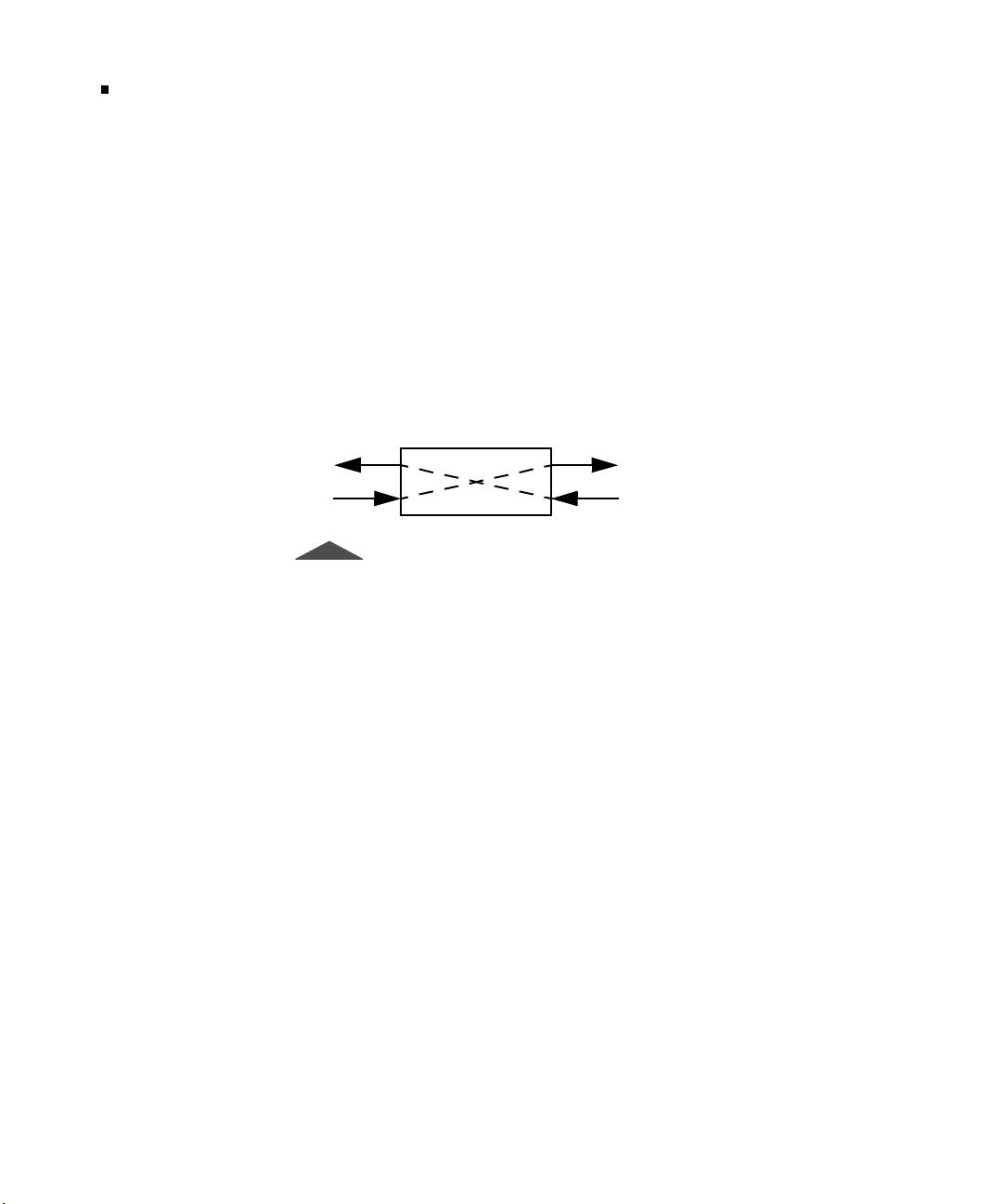
and receive side of the T1 path are paired. As shown in Figure 1, the
input signal is received, Bipolar Violations (BPVs) are corrected, the
signal is regenerated, and new data can be inserted onto specific
bandwidths before the signal is sent to the output. No data is inserted
on the transmit path unless the associated receiver has frame
synchronization. The D&I mode signal paths are illustrated in Figure
1.
Line Equipment
Tx
Rx
Figure 1 • D&I Mode Paths
Tx
Rx
Dual Monitor (Mon) Mode
This mode measures signal parameters, monitors traffic from a
resistor-isolated DS1 monitor point, or bridges onto the line. One (1)
or two (2) receivers may be used. If two (2) receivers are used, the
LINE and EQUIPMENT receivers are monitored simultaneously.
Line Loop Back (LLB) Mode
This mode places the T1 path into Full Loop Back configuration,
which loops the incoming data back out the transmitter while
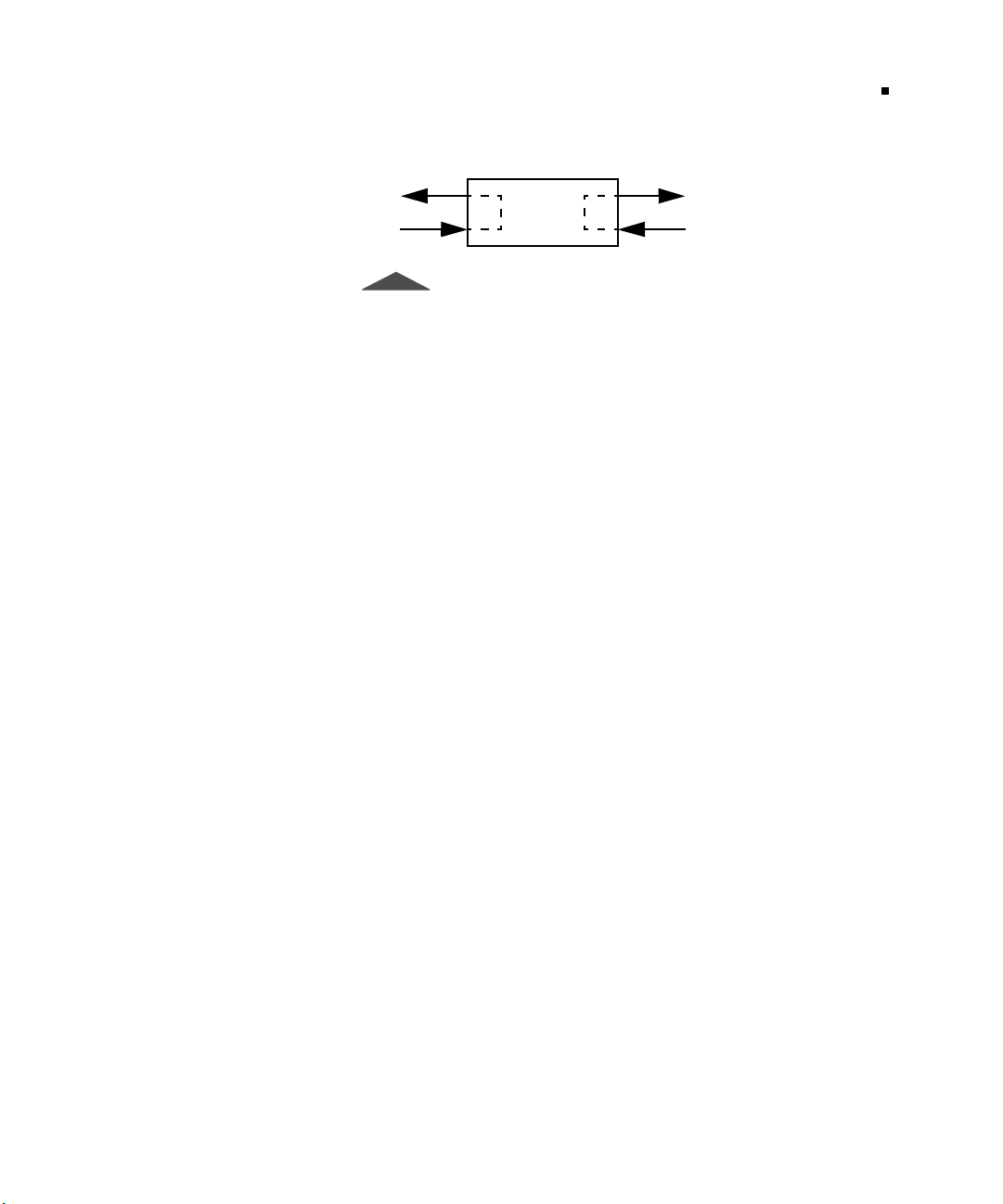
enabling the receiver to monitor the incoming signal (BPV errors are
not corrected). The LLB mode signal paths are illustrated in Figure 2.
T-BERD 950 User’s Guide
Page 31
Front Panel Controls, Indicators, and Connectors
Chapter 2 — Instrument Setup and Description
Line Equipment
9
Tx
Rx
Figure 2 • LLB Mode Paths
Tx
Rx
Self Loop Mode
When the T-BERD 950 is placed in Self Loop mode (press
key), a set of relays is activated. These relays are designed to
LOOP
pass the incoming signal through the T-BERD 950. The signal path is
from Rx LINE to Tx EQUIPMENT, and from Rx EQUIPMENT to
Tx LINE. This is the same configuration as for D&I Mode.
If a D&I test is being performed, and the T-BERD 950 is placed in
Self Loop mode; the incoming signal still passes through it without
interruption. If it is in Terminate Mode, where the configuration is Tx
LINE to Rx LINE, the relays have no effect. The relays remain active
when the unit loses power or is powered off.
SELF
Front Panel Controls, Indicators, and Connectors
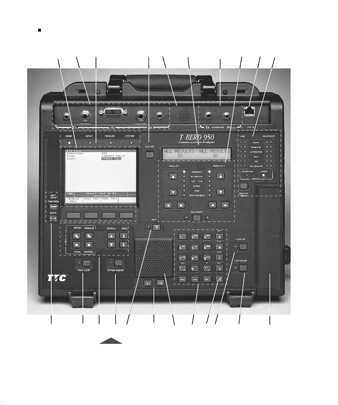
The front panel of the T-BERD 950 mainframe is shown in Figure 3
with each control (or control group), indicator, and connector marked
with a numbered callout. Table 1 provides a brief description of each
control, indicator, and connector referenced to the numbered callouts
in Figure 3.
T-BERD 950 User’s Guide
Page 32
Front Panel Controls, Indicators, and Connectors
10
Chapter 2 — Instrument Setup and Description
12 3 45 6 7 8 9 10
11 12 13 14 15
T-BERD 950 User’s Guide
Figure 3 • Front Panel
17
18
19
20
21 2216
Page 33

Front Panel Controls, Indicators, and Connectors
Chapter 2 — Instrument Setup and Description
Table 1 • Front Panel Controls, Indicators, and Connectors
No Control Indicator Description
1 Large Graphical Display Shows four unique views:
Home — Configures the interface, task, and test to be
performed.
Setup — Configures the specifics of the selected test.
Results — Shows results for the selected test.
System — Configures general mainframe and auxiliary
settings.
11
2 T1 LINE Tx and Rx
Connectors
3 Large Graphical Display
LED
4
5 Microphone Used for Voice testing, activated by the PUSH-TO-TALK key on
6 Two-Line Display Shows LINE and EQUIPMENT receiver results. Line receiver
7 T1 EQUIPMENT Tx and
8 RESULTS I and II Display
RESTART Key
Rx Connectors
Area Controls & Indicators
Consists of one set of WECO 310 female connectors, one set of
Bantam female connectors, and one 15-pin D connector for
LINE Tx and Rx. This is also referred to as Primary Side.
Illuminates to indicate which view is active.
Generates a manual test restart and clears all results, including
any flashing messages on the Two-Line Display.
the keypad.
results appear unless the EQUIPMENT Key is used to show
EQUIPMENT receiver results (see Callout #8). Also shows
status and alarm messages.
Connects one set of Bantam female connectors for the
EQUIPMENT Tx and Rx. This is also referred to as Secondary
Side.
Up/Down Arrow Keys — Selects the results category.
Left/Right Arrow Keys — Selects the individual result within
the selected category.
Category Light Emitting Diodes (LEDs) — Illuminates to
indicate the selected category.
EQUIPMENT Key — Selects EQUIPMENT channel results for
the RESULTS I and II display areas. The LEDs under RESULTS
I and II light to indicate that EQUIPMENT channel results are
shown. If the LED is off, LINE side results appear.
T-BERD 950 User’s Guide
Page 34

Front Panel Controls, Indicators, and Connectors
12
Chapter 2 — Instrument Setup and Description
Table 1 • Front Panel Controls, Indicators, and Connectors (Continued)
No Control Indicator Description
9 DDS Local Loop
Connector
10 Status/Alarm Group
11
SOFTKEYS Control
Group
Connects RJ45 connector for four wire Digital Data Service
(DDS) Local Loop Option.
Status/Alarm LEDs — (inside LEDs) Illuminates green to
indicate Signal Present, Frame Sync, Pattern Sync, and B8ZS
detection. Illuminates red for AIS and Yellow Alarm for LINE
and EQUIPMENT channels.
History LEDs — (outside LEDs) Illuminates red to indicate
that a status/alarm condition has changed state for Signal
Present, Frame Sync, Pattern Sync, B8ZS detection, AIS, and
Yellow Alarm, for both LINE and EQUIPMENT channels. Press
RESTART or HISTORY RESET to clear.
HISTORY RESET Key — Clears all history LEDs. It does not
clear an active alarm LED.
Low Battery LED — Illuminates to indicate that the batteries
have less than 15 minutes of charge remaining.
NOTE: This LED also illuminates when the T-BERD 950 is
powered on and remains on (for approximately 30 seconds) until
the internal battery test circuitry determines the amount of
charge remaining in the battery.
Charge LED — Steady illumination indicates that the
battery(ies) is being charged at the maximum rate. It blinks to
indicate that the battery is being trickle charged.
FUNCTION — Shows the current available softkey groups.
MORE — Shows additional softkeys.
12
T-BERD 950 User’s Guide
SELF LOOP Key
Softkeys — Use to make selections for the currently highlighted
field.
Loops the selected interface transmitter to its receiver. The LED
illuminates indicating self loop is active. When in self loop
mode, the T-BERD 950 is isolated from the LINE and
EQUIPMENT connectors.
When SELF LOOP operation is turned On, the T-BERD 950
operating mode is automatically set to TERMINATE, the
transmit timing is set to INTERNAL and Line Build Out (LBO)
is set to 0 db. When the SELF LOOP operation is turned Off, the
T-BERD 950 returns to its previous configuration.
Page 35

Front Panel Controls, Indicators, and Connectors
Chapter 2 — Instrument Setup and Description
Table 1 • Front Panel Controls, Indicators, and Connectors (Continued)
No Control Indicator Description
13
13 Large Graphical Display
Controls Group
14
15
16
17 Speaker Allows you to hear audible VF tones present (i.e., voice, TIMS
18 Alphanumeric Keypad Consists of a telephone keypad. See Table 2, on page 14, for
19
20
ERROR INSERT Key
HELP Key
VOLUM E Keys
PUSH-TO-TALK Key
LOOP UP Key
VIEWS Control Keys (HOME, SETUP, RESULTS and
SYSTEM) — Provide access to the Home, Setup, Results, and
System views.
SCROLL Keys — Move one item at a time up or down the list
on the current view.
PAG E Keys — Scroll up or down a full screen at a time when
PGUP or PGDN appear on the right side of the prompting area.
Inserts a single error or errors at a specified rate. If the key is
pressed for more than two (2) seconds, the LED illuminates to
indicate that error rates are being inserted.
Accesses help for the active selection line.
Controls the volume of the speaker. The left key reduces the
volume and the right key increases the volume.
tones).
detailed functions of the special keys.
Activates the microphone feature.
Activates loop up code transmission. The LED illuminates to
indicate loop up code is being transmitted.
21
22 Interface Module Slot Provides slot for optional interface module use, such as the
LOOP DOWN Key
Activates loop down code transmission. The LED illuminates to
indicate loop down code is being transmitted.
Analog 2W/4W or Datacom (DTE/DCE) interface modules.
T-BERD 950 User’s Guide
Page 36
Left Side Panel Controls and Connectors
14
Chapter 2 — Instrument Setup and Description
Keypad
The keypad consists of a telephone keypad and has additional keys for
signaling entry and HEX-based input. Special keys are described in
Table 2.
Tabl e 2 • Keypad Special Function s
Key Description
A, B, C, D
*/E
#/F
D/±
DEL
(← →)
Push-to-Talk
Adds DTMF signaling when setting the Program Dial feature for some
options. The STP, ST2P, and ST3P markings above the keys are for MF
signaling. Also used for entering HEX information.
Adds DTMF signaling and KP for MF signaling. Also used for entering
HEX information and a decimal point (.)
Adds DTMF signaling and ST for MF signaling. Also used for entering
HEX information.
Toggles a level value from positive (+) to negative (-).
Deletes the selected character.
Moves the cursor left or right.
Provides Push-to-Talk microphone activation.
Left Side Panel Controls and Connectors
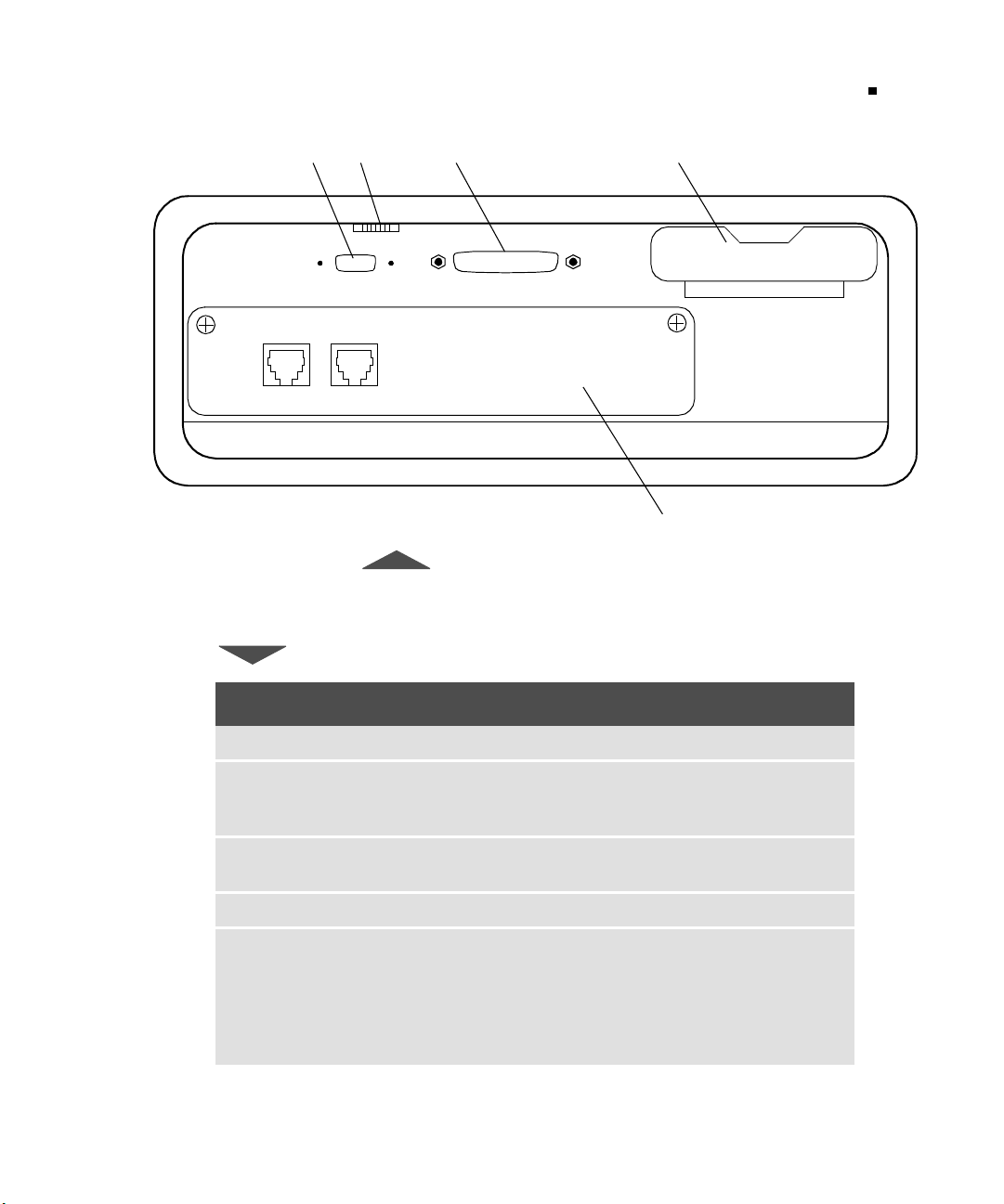
The left side panel of the T-BERD 950 mainframe is shown in Figure
4. Each control and connector is marked with a numbered callout.
Table 3 describes each control and connector labeled in Figure 4.
T-BERD 950 User’s Guide
Page 37
Left Side Panel Controls and Connectors
Chapter 2 — Instrument Setup and Description
12 3 4
CONTRAST
15
AUX PORT
U Interface
To LTTo N T
RS-232 PRINT/CONTROL
5
Figure 4 • Left Side Panel
Table 3 • Left Side Panel Description
No. Control Indicator Description
1 AUX PORT Future use.
2 CONTRAST Adjusts the backlight on the Large Graphical Display.
Note: If the contrast is not set properly, the display
appears blank.
3 RS-232 PRINT/
Connects to the RS-232 side of the printer cable.
CONTROL
4 PCMCIA Card Slot Used for the T-BERD 950 software card.
5 Option Slot Used for the Protocol Services Board (Acterna Part #
TB950-PSB).
U interface connectors are present, but the ISDN BRI
software option (Acterna# TB950-BRI) must be installed
to perform ISDN BRI testing. For details see “External
Interface Requirements” on page 223.
T-BERD 950 User’s Guide
Page 38

Right Side Panel Controls and Connectors
16
Chapter 2 — Instrument Setup and Description
Using the PCMCIA Card Slot
Insert the T-BERD 950 software card.
1.
Turn power off.
2.
Open the PCMCIA access door, the hinged cover over the
port on the right side.
The inside of the door is marked “OPTION - Top Eject” on
the left and “SOFTWARE - Bottom Eject” on the right.
3.
Insert your software in the bottom slot.
The top slot is for future use.
To remove the PCMCIA software card, press the small release button
on the right side of the software slot. Do not try to pull it out.
Right Side Panel Controls and Connectors
T-BERD 950 User’s Guide
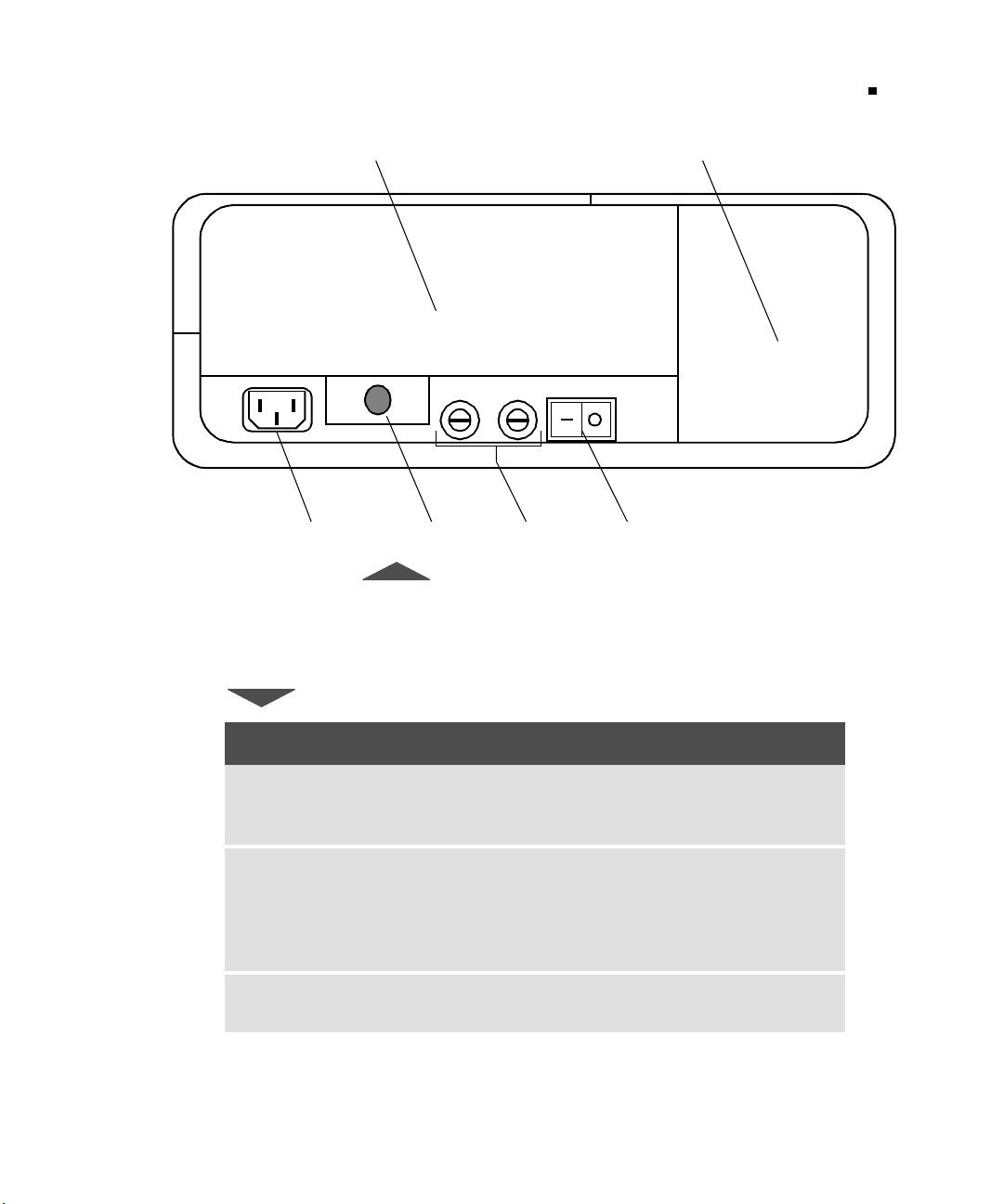
The right side panel of the T-BERD 950 mainframe is shown in
Figure 5. Each control and connector is marked with a numbered
callout. Table 4 describes each control and connector referenced to
the numbered callouts in Figure 5.
Page 39
Right Side Panel Controls and Connectors
Chapter 2 — Instrument Setup and Description
12
3456
Figure 5 • Right Side Panel View
17
Tabl e 4 • Right Side Panel Controls and Connector s
No. Control Indicator Description
1
Interface Module Slot Contains optional interfaces, such as
the Analog 2W/4W or Datacom (DTC/
DCE) Interface Modules.
2
Fan Cools the T-BERD 950 when con-
nected to AC power and when the batteries are being charged. During test
operations, the fan is controlled by its
internal temperature.
3
AC Power Receptacle Connects the AC power cord to the
T-BERD 950.
T-BERD 950 User’s Guide
Page 40

Rear Panel
18
Chapter 2 — Instrument Setup and Description
Tabl e 4 • Right Side Panel Controls and Connectors (Continued)
No. Control Indicator Description
4
Interface Module Release
Button or Lever
5
6
AC L in e Fuses Contains two 250 Volt, 1 Amp Slo-Blo
Power Switch Powers the T-BERD 950 On or
Rear Panel
Releases an interface module for
removal. To release the installed interface module, press the button or pull
the lever.
fuses (LittleFuse p/n 218 001).
Off (I
or O).
The rear panel of the T-BERD 950 mainframe is shown in Figure 6.
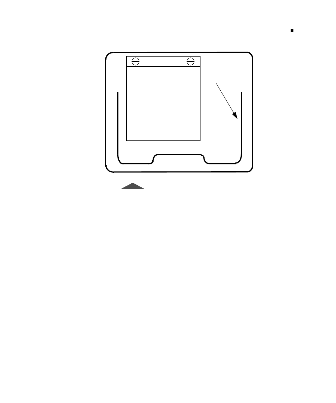
As shown in Figure 6, access to the rechargeable batteries is through
the battery compartment door. The tilt stand can be adjusted to stand
the T-BERD 950 at an angle for easier viewing of the display screens.
T-BERD 950 User’s Guide
Page 41
Chapter 2 — Instrument Setup and Description
Battery
Compartment
Door
Figure 6 • Rear Panel View
Tilt Stand
Battery Operation
19
Battery Operation
The T-BERD 950 uses battery power when AC power is not
available. It does so by automatically switching over to battery power
when AC power is lost. The rechargeable batteries provide between 2
and 4 hours of operating time. Depending on the tests performed and
the configuration, the operating time can vary.
Charging Batteries
The batteries are charged whenever the T-BERD 950 is connected to
AC power. When
When the T-BERD 950 is powered On, the number of batteries
, the charging time is approximately 3 hours.
Off
T-BERD 950 User’s Guide
Page 42

Battery Operation
20
Chapter 2 — Instrument Setup and Description
charged and the time required to reach full power is determined by the
installed options and configuration of the T-BERD 950. To reach full
power, recharging may require up to 8 hours.
Battery charging is not supported in some configurations (i.e., Frame
Relay and ISDN PRI). To start charging, either power off the
T-BERD 950 or select a configuration that supports charging.
Two LEDs are located on the front panel of the T-BERD 950 to
indicate the status of the batteries:
■
Charge LED
— Illuminates steady to indicate that the batteries
are being charged at the maximum charge rate. Blinks to
indicate that the batteries are fully charged and the charger is
producing a trickle charge to maintain the batteries at a full
charge, while the T-BERD 950 is turned Off.
■
Low Battery LED
have less than 15 minutes of charge remaining.
Charge LED
and
Low Battery LED
— Illuminates to indicate that the batteries
.
The
BATT CHG
result (Time Results Category) becomes invalid
when the batteries are removed. The batteries must be
conditioned to obtain a valid Battery Charge result.
Battery Replacement Procedure
To replace the batteries follow these instructions:
1.
Power off the T-BERD 950 and disconnect the AC power
cord.
If the current configuration supports battery charging, the
batteries can be changed one at a time while the test is in
progress without interrupting T-BERD 950 performance.
The batteries can be “hot swapped” (i.e., one at a time when
T-BERD 950 is powered
BATT CHG
result (Time Results Category) becomes invalid
until the batteries are conditioned.
). If you do so, remember that the
ON
T-BERD 950 User’s Guide
Page 43

Battery Operation
Chapter 2 — Instrument Setup and Description
2.
Open the battery compartment door, located on the rear panel
of T-BERD 950, by turning the two fasteners ¼ turn
counterclockwise.
3.
Remove each of the batteries individually. Using the cloth
strap, lift the end of the battery away from the contacts.
4.
Allow one (1) minute between removal and installation of the
batteries to enable the battery capacity measurement to reset.
5.
Install the new battery by inserting the contact end first and
firmly press down on the end away from the contacts.
Battery contacts are offset to prevent incorrect installation.
6.
Close the battery compartment door and secure it by turning
the two fasteners ¼ turn clockwise.
Condition the batteries to obtain accurate battery capacity
readings. (Refer to pag e37 in Chapter 3 for additional
information.) Allow the batteries to charge to full capacity
prior to operating T-BERD 950 on battery power. The
batteries will charge when the unit has AC power.
21
Preventive Maintenance
Preventive maintenance on the T-BERD 950 involves two steps:
visually inspecting it and cleaning it. The T-BERD 950 should be
visually inspected and cleaned as often as operating conditions
require.
The accumulation of dirt on the T-BERD 950 can cause
overheating and component failure.
T-BERD 950 User’s Guide
Page 44

Battery Operation
22
Chapter 2 — Instrument Setup and Description
Exterior Inspection
Inspect the external portions of the instrument for damage, wear, and
loose or missing parts. Check all parts thoroughly to verify correct
operation and performance.
Any deficiencies found that could cause personal injury or
lead to further damage indicate that the unit should not be
used.
Exterior Cleaning
Loose dust on the outside of the instrument can be removed with a
soft cloth. Remove any dirt that remains with a soft cloth dampened in
a mild detergent and water solution (e.g., Miller Stephenson Cleaner
MS-260).
T-BERD 950 User’s Guide
Do not use abrasive cleaners on the Large Graphical Display
or Two-Line Display screen as the screens could be
scratched. Do not get moisture inside the instrument.
Use only enough water to dampen the cloth. Any accumulated dust
and dirt in the fan input area can be removed with a vacuum.
Replacing the Fuse
The procedure to replace the AC power fuse(s) in the T-BERD 950 is
presented below.
1.
Power off the T-BERD 950 and disconnect the AC power
cord.
2.
Remove the fuse holder(s) by turning it ¼ turn
counterclockwise while pulling the fuse out of the holder.
Page 45

Battery Operation
Chapter 2 — Instrument Setup and Description
The fuse holders are located on the right side panel of
T-BERD 950, immediately to the left of the Power switch. See
item 4 of Figur e5 on page 17.
3.
Insert the replacement fuse (Replace with a fuse of the proper
rating and voltage (i.e., T1A/250V). See the label on the
bottom of the T-BERD 950 for fuse type.) into the holder and
reinstall the fuse holder by turning it ¼ turn
counterclockwise.
4.
Reconnect the AC power cord.
23
T-BERD 950 User’s Guide
Page 46

Battery Operation
24
Chapter 2 — Instrument Setup and Description
T-BERD 950 User’s Guide
Page 47
Chapter
Large Graphical
Display
3
his chapter describes the operation of the Large Graphical Display
and the Home, Setup, Results, and System views.
T
Operation
T-BERD 950 User’s Guide
Page 48
Main Display Controls
26
Chapter 3 — Large Graphical Display Operation
Main Display Controls
The following paragraphs describe the operation of the front panel
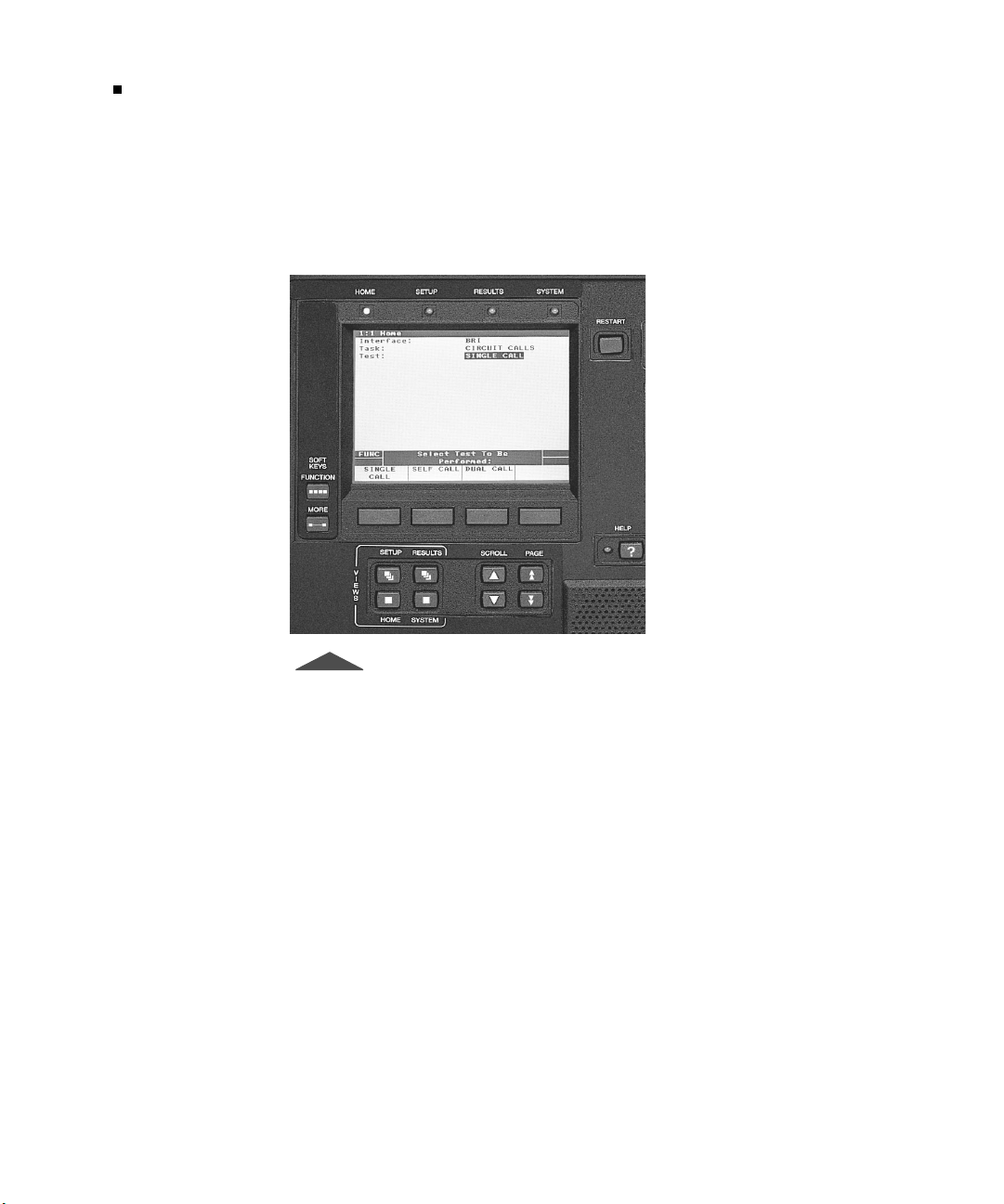
controls associated with the Large Graphical Display. Figure 7 shows
the controls and LEDs for the Large Graphical Display.
T-BERD 950 User’s Guide
Figure 7 • Main Display and Controls
Large Graphical Display LEDs
The LEDs above the Large Graphical Display correspond to the view
that is active on the display. For example, when the Setup view is
active, the
SETUP
LED illuminates.
Views Keys
The Views keys
HOME, SETUP, RESULTS
to various views on the Large Graphical Display as follows:
, and
SYSTEM
provide access
Page 49

Main Display Controls
Chapter 3 — Large Graphical Display Operation
— Allows you to choose the Test Interface, the Task
HOME
(TNT or Manual), or the Test Type.
— Allows you to set the test parameters for the
SETUP
selected Test Interface, Task, and Test Type. Press the
key to access the TNT view, or to change the view to
Interface or Test Type.
27
SETUP
RESULTS
— Allows you to view the test results for these Test
Result views: TNT, Summary, Interface, Test Type, Signal,
Time, Performance, and Alarms. Press the
RESULTS
view each page.
SYSTEM
— Allows you to set general mainframe and
auxiliary settings.
Scroll and Page Keys
The
SCROLL
menu items. The
through the display when the PGUP or PGDN indicators appear in the
prompting area. If you only have one page, the up arrow
moves the active selection line to the top of the display. The down
arrow
display.
keys (up and down arrow) are used to scroll through the
keys (up and down arrows) are used to page
PAG E
key moves the active selection line to the bottom of the
PAG E
Help Key
The
(shown in reverse video) on the Large Graphical Display. Pressing the
key once activates the help function (the LED to the left of the key
illuminates) and the available help for the selected menu item will
appear. Pressing the
function (LED turns off).
key accesses the available help for the active selection line
HELP
key a second time turns off the help
HELP
PAG E
key to
key
If the active selection line is a data entry type field, instructions are
provided that explain how to edit the field data. Help must be turned
off to edit the field.
T-BERD 950 User’s Guide
Page 50

Main Display Controls
28
Chapter 3 — Large Graphical Display Operation
Softkeys Controls
The SOFTKEYS Control keys, located to the left of the Large
Graphical Display, operate the softkey groups.
The
FUNCTION
key shows all available softkey groups for the current
test and when available, “FUNC” appears on the left side o the
Prompting area.
The
key shows additional softkeys available within the current
MORE
softkey group. If there are more than four selections available,
“MORE” appears on the left side of the Prompting area.
Softkeys
The softkeys (located immediately below the Large Graphical
Display) are used to make selections and activate the functions that
appear at the bottom of the Large Graphical Display. The function
may be related to a single selection line or to a group of items. The
SOFTKEYS
softkeys.
In addition to selecting the parameter for your test, the softkeys
provide additional functionality based on the type of information you
may need to set up your test. Some selections require a numeric or
alphanumeric input. Depending on the type of information, softkeys
appear allowing you to add or change the information in the field. For
example, the
information. When selected, the Edit Channels Map popup screen
appears.
Controls (
softkey appears for you to change numeric
Edit
FUNC
and
) allow you to navigate the
MORE
T-BERD 950 User’s Guide
Edit Softkey
When a channel needs to be selected, the
these steps to make your selection.
softkey appears. Follow
Edit
Page 51

Main Display Controls
Chapter 3 — Large Graphical Display Operation
1.
Press
Deselect
to access the Edit Channels screen and the
Edit
,
Clear All, Abort Changes
, and
Save & Exit
The Edit Channels screen enables configuration of the active
channels for both the T1 LINE and T1 EQUIPMENT
interfaces (the selected channels are the same for both
interfaces).
2.
Use the
SCROLL
keys to move from channel to channel.
29
Select/
softkeys.
Select/Deselect
The
softkey toggles the channel between
active and inactive.
Clear All
The
Abort Changes
The
softkey deselects all channels.
softkey exits the Edit Channels screen
without making any changes to the existing channel
selections and returns you to the previous screen.
3.
Press
Save & Exit
to enter all changes and return to the Setup
view.
Increase or Decrease Value Softkeys
The
INCREASE VALUE, DECREASE VALUE
when selection lines require a numeric input.
1.
Press
Increase Value
or
Decrease Value
the value.
You may also use the keypad to change the value in the field.
2.
Press
to set the value.
OK
, and OK softkeys appear
to increase or decrease
Clear, Home, and End Softkeys
These softkeys appear when you need to edit a user-programmable
field such as
1.
Long User Pattern.
Press
softkey and a popup window and additional
EDIT
softkeys appear.
— Clears the field.
Clear
T-BERD 950 User’s Guide
Page 52

Large Graphical Display
30
Chapter 3 — Large Graphical Display Operation
— Places the cursor at the beginning of the
Home
string.
— Places the cursor at the end of the string.
End
2.
Press the 1 through 9, or 0 key on keypad to select a character
set. The assigned values for that key will appear in the popup
window.
3.
Press the corresponding number for the character you want to
place into the user data information. Press 0 to add spaces if
needed.
4.
Repeat steps 2 and 3 until your loop code label is complete.
5.
Press
SCROLL
line.
Large Graphical Display
The four views available on the Large Graphical Display provide easy
access to TNT and manual test setups, test configurations, results, and
mainframe configurations.
when finished to move to the next selection
T-BERD 950 User’s Guide
Home View
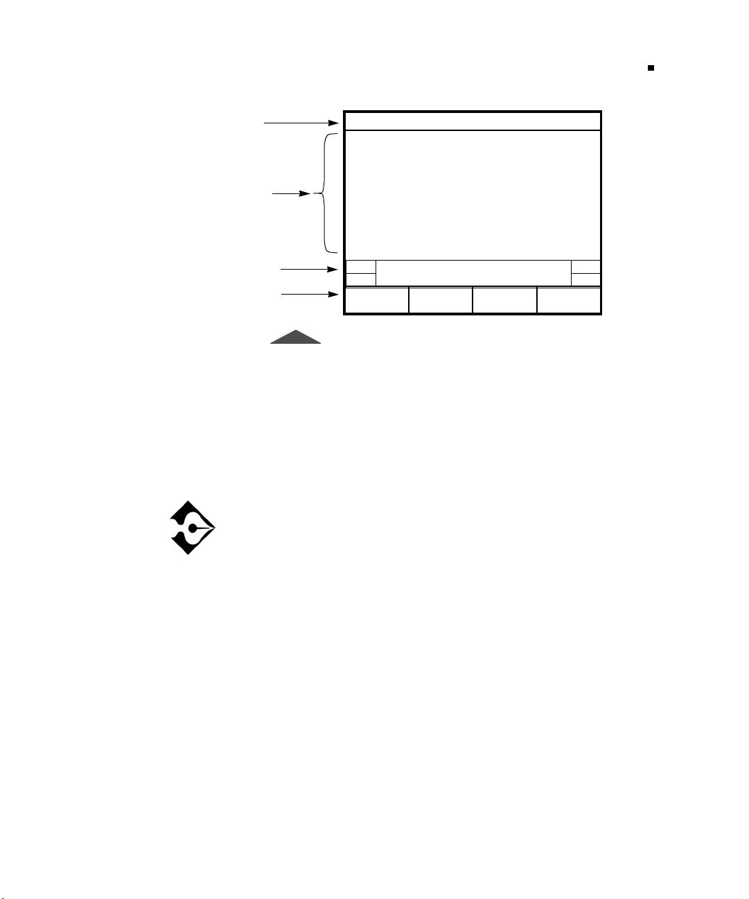
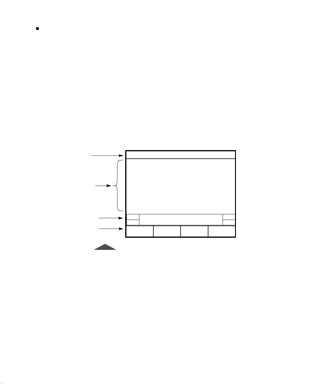
The Home view (see Figure 8) allows you to select the interface, task,
and test you want to perform. The display is divided into four areas:
title bar, selection area, prompting area, and softkey descriptions. The
following paragraphs describe the function of each area of the Home
view.
Title Bar
The top line of the display, called the title bar (see Figure 8), indicates
the current view and view type of the Large Graphical Display.
Page 53
Large Graphical Display
Chapter 3 — Large Graphical Display Operation
31
Title Bar
Selection
Area
Prompting
Area
Softkeys
1:1 Home
Performed:
Interface: T1
Task: MANUAL SETUP
Test Type: BERT
FUNC S elect Task To Be
MANUAL
SETUP
Figure 8 • Home View
Selection Area
The selection area enables you to control all of the analyzer
configuration selections (see Figure 8). Use the
SCROLL
navigate the selection area and make the required changes.
keys to
The change takes effect after one second, after exiting the
active selection line, or changing the active display screen.
Prompting Area
The area on the Large Graphical Display above the softkeys is the
prompting area. This area prompts you to perform a specific action
based on the current softkey group.
T-BERD 950 User’s Guide
Page 54
Large Graphical Display
32
Chapter 3 — Large Graphical Display Operation
Softkeys
Softkeys show the available choices for each selection line to
configure the unit for your test.
Setup View
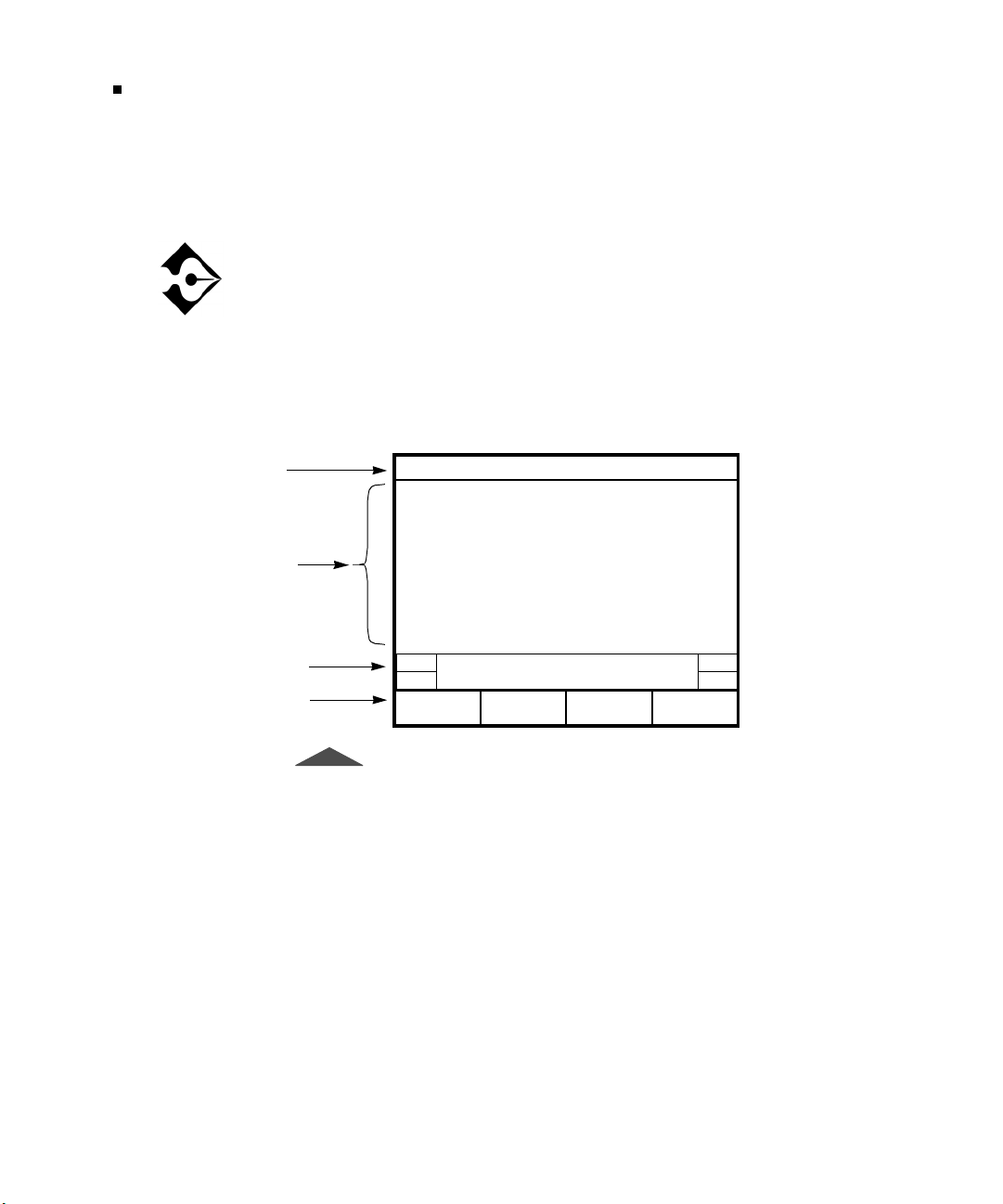
The Setup view, shown in Figure 9, is used to set the parameters for
the interface, task, or test type selected on the Home view. The
display is divided into four areas: title bar, selection area, prompting
area, and softkey descriptions. The following paragraphs describe the
function of each area of the Setup view.
Title Bar
Selection
Area
Prompting
Area
Softkeys
1:3 Interface T1 Send Loopback (NIU)
Mode: TERMINATE
Framing: AUTO
Payload: FULL
Line Coding: B8ZS
Line Rx In: TERM
Equip Rx In: TERM
Tx Timing: INTERNAL
Loopcode: CSU
Auto Respond: ON
Line LBO: 0 db
Yellow Alarm: OFF
FUNC
MORE
Select Mode:
D&I MONITO R LLBTERMINATE
Figure 9 • Interface Setup View
Title Bar
The title bar (see Figure 9) indicates the interface in use and the test
type to be performed. Press
SETUP
and Test Type configurations. The active view is also indicated by the
illuminated LED above the Large Graphical Display.
to toggle between TNT, Interface,
T-BERD 950 User’s Guide
Page 55

Large Graphical Display
Chapter 3 — Large Graphical Display Operation
Selection Area
The selection area enables you to control all of the analyzer
configuration selections (see Figure 9)). Use the
SCROLL
keys to navigate the selection area and make the required change.
The change takes effect after one second, after exiting the
active selection line or changing the active display screen.
Prompting Area
The prompting area prompts you to perform a specific action based
on the current softkey group (see Figure 9). The PGUP and PGDN
indicators appear in this area of the display when the view has more
than one page of parameters. Press the
results.
keys to view additional
PAGE
and
33
PAG E
Softkeys
Softkeys show the available choices of each selection line to
configure your test (Figure 9). These softkeys appear as choices, or as
functions of the selected option.
Results View
The Results view is used to display data for each of the Results
categories (i.e., TNT, Summary, Interface, Test Type, Signal, Time,
and Performance). In addition, the Results view also lists the date and
time the alarm occurred, as well as where the alarm occurred, i.e., the
LINE (Primary) or EQUIPMENT (Secondary) side. A sample
Interface Results view is shown in Figure 10.
T-BERD 950 User’s Guide
Page 56
Large Graphical Display
34
Chapter 3 — Large Graphical Display Operation
In the event that one Results view is not sufficient to show all of the
results for a given category, the PGUP or PGDN indicator will appear
on the right side of the prompting area. Use the
the results up and down.
If all results are within specification for the LINE (Primary)
and EQUIPMENT (Secondary) receivers, the message “All
Results OK” will appear on the Results view.
The display is divided into four areas: title bar, selection area,
prompting area, and softkey descriptions. The following paragraphs
describe the function of each area of the Results view.
keys to scroll
PAG E
Title Bar
Selection
Area
Prompting
Area
Softkey
Descriptions
1:3 Interface T1-BERT
LINE
BPVs 0
BPV Seconds 0
BPV Rate 0
Frm Errors 0
Frm Er Rate 0
Frm Er Sec 0
Frm Los Cnt 0
Frm Los Sec 0
CRC Errors 0
CRC Err Sec 0
CRC Err Rate 0
Press HELP for Additional
Result Information.
PRINT
SCREEN
PGDN
Figure 10 • Interface Results View
Title Bar
The title bar displays the view number 1:8 (one of eight) and the
current Results view (TNT, Summary, Interface, Test Type, Signal,
Time, Performance, or Alarm). Press the
next result view.
RESULTS
key to display the
T-BERD 950 User’s Guide
Page 57

Large Graphical Display
Chapter 3 — Large Graphical Display Operation
35
Display Area
The display area shows the list of results for the selected view. The
SCROLL
keys can be used to scroll up and down through the list of
results. The left column lists LINE (Primary) results and the right
column lists EQUIPMENT (Secondary) results.
Prompting Area
The prompting area prompts you to perform a specific action based
on the current softkey group (see Figure 10 on page 34). The PGUP
and PGDN indicators appear in this area of the display when the view
has more than one page of results. Press the
keys to view
PAG E
additional results.
Softkeys
Softkeys appear to show the functions available in the Results view.
System View
The System view, shown in Figure 11, provides access to system
parameters for the mainframe and other auxiliary functions. The
display is divided into four areas: title bar, selection area, prompting
area, and softkey descriptions. The following paragraphs describe the
function of each area of the System view.
T-BERD 950 User’s Guide
Page 58
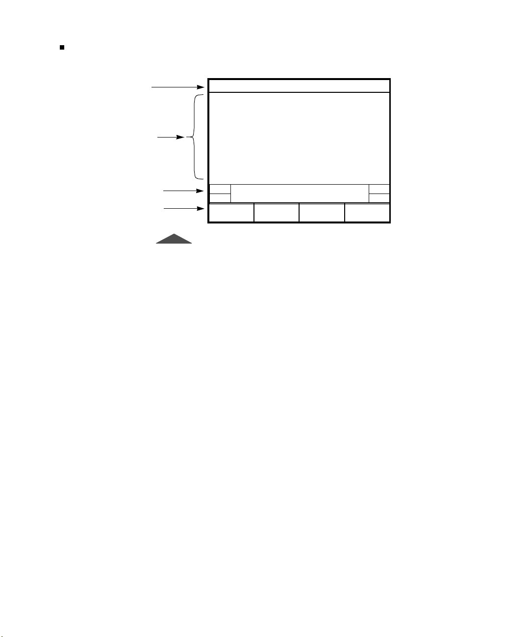
Large Graphical Display
36
Chapter 3 — Large Graphical Display Operation
Title Bar
Selection
Area
Prompting
Area
Softkeys
1:1 AUX
PRINT
SCREEN
Date 01/01/ 99
Time: (HH:MM:SS): 0 0:06:14
Timed Test Type: C ONTINUOUS
Microphone: PUSH TO TALK
Display Backlight: ON
System Information: Softkeys
Condition Battery: NO
Alarm Category: No
Power Loss Detect: YES
Factory Defaults: NO
Printer Info: HIDE
Reverse Display: YES
FUNC Sele ct Date:
Figure 11 • System View
Title Bar
The title bar shows the current usage for the System view (Auxiliary).
Selection Area
T-BERD 950 User’s Guide
The selection area is used to configure System functions. Use the
SCROLL
keys to select the active selection line. Softkeys become
available to choose the appropriate configuration. Data entry fields
are edited using the keypad.
The following paragraphs provide a description of each System
parameter, the choices available, and how to select or edit the
parameter. Use the available softkeys in combination with the keypad
to edit these parameters.
— Displays the date in MM/DD/YY (Month/Day/Year) format.
Date
— Displays the time in HH:MM:SS (Hours:Minutes:Seconds)
Time
format.
Page 59

Large Graphical Display
Chapter 3 — Large Graphical Display Operation
37
Timed Test Type
or
TIMED
— Selects the type of test to be run. The choices are
CONTINUOUS
. If
is selected the following selection
TIMED
line will appear and must be configured.
Length
— Used to enter the amount of time, in HHH:MM
(Hours:Minutes) format, that a timed test is to run. A time of
zero (0) causes continuous testing.
When
CONTINUOUS
until the
RESTART
is selected the test runs continuously
key is pressed or the analyzer is powered
off.
Microphone
PUSH-TO-TALK.
Display Backlight
— Displays the default microphone operating mode
— Used to vary the length of time the display
backlight remains on. Turning off the backlight will extend operating
time when operating on battery power. The choices include the
following:
AUTO 5 MIN
— Turns the backlight on for 5 minutes when a
front panel key is pressed. If no front panel key is pressed for
a period of 5 minutes, the backlight is turned off.
— Turns the backlight on.
ON
— Turns the backlight off.
OFF
System Information
information. The following softkeys are will appear when
Information
is selected:
SOFTWARE VERSIONS
— Used to show system option and version
System
— Displays the versions of all
software on the system PCMCIA card.
INSTALLED OPTIONS
— Displays the hardware and software
options currently installed.
UPGRADE CARD INFO
— Displays the uninstalled options
available on a system PCMCIA card.
Condition Battery
— Used to reset the internal fuel gauge maximum
capacity to the actual available capacity of the batteries when fully
charged. This function should be used whenever the batteries are
T-BERD 950 User’s Guide
Page 60

Large Graphical Display
38
Chapter 3 — Large Graphical Display Operation
changed, the Battery Performance Index (BPI) or Battery Capacity
result is “Invalid,” or the reported capacity of the batteries does not
correlate to the actual operating time available.
The battery conditioning cycle can take as long as 12 hours if it is
started with fully discharged batteries. During the cycle, the analyzer
should be left
and not disturbed. At the end of conditioning, the
On
BPI result is updated to reflect the total capacity of the batteries when
fully charged. This capacity will diminish over time as the batteries
wear (this is normal). If the BPI is below 50%, you should contact
Acterna to obtain new batteries.
Alarm Category
— Controls whether a notification message appears
on the Two-Line Display when an alarm is detected.
ALERT ON UPDATES —
Alerts you to verify the alarm logged
in the Alarm Result view.
DON’T ALERT
— Disables the notification message but
alarms are still logged.
Power Loss Detect
and incrementing of the
YES
analyzer is powered on. The
when the
NO —
Factory Defaults
— Setting this function to
result on the Time view.
result increments each time the
Power Loss
result is not shown.
— The
RESTART
The
Power Loss
Power Loss
key is pressed.
Power Loss
— Used to clear the nonvolatile random access
memory (NOVRAM). The choices are
— Opens confirmation popup window. This window
YES
NO
enables detection
Yes
result is cleared
or
.
YES
states that the NOVRAM will be reset to the factory defaults
and the analyzer will reboot.
Printer Info
— Select one of the following choices. Default is
— Hides the options for printer operation.
HIDE
HIDE
.
T-BERD 950 User’s Guide
DISPLAY
— Shows other options to set up the print
configuration. See “Printer Configuration” on page 106 for
more details.
Page 61

Large Graphical Display
Chapter 3 — Large Graphical Display Operation
39
Reverse Display
— Used to reverse the display from white letters on
blue background to blue letters on white background. Default is white
on blue. Choices are
YES
and NO.
Prompting Area
The area on the large graphical display above the softkeys is the
prompting area. This area prompts you to perform a specific action
based on the current softkey group.
Softkeys
Softkeys appear to show the available choices of each selection line
for you to configure the unit for your test.
T-BERD 950 User’s Guide
Page 62

Large Graphical Display
40
Chapter 3 — Large Graphical Display Operation
T-BERD 950 User’s Guide
Page 63
Chapter
Specifications
4
his section describes the physical and test specifications of the
T-BERD 950.
T
T-BERD 950 User’s Guide
Page 64

Physical Specifications
42
Chapter 4 — Specifications
Physical Specifications
The physical specifications for the T-BERD 950 are presented in
Table 5.
Table 5 • Physical Specifications
Specification Value
Physical:
Height:
Width:
Depth:
Weight:
Environmental:
Temperature:
Operating:
Non-Operating:
Humidity:
Vibration:
Shock:
Altitude:
Operating:
Non-operating storage
or transportation:
10.5" (26.68 cm)
13.25" (33.66 cm)
4" (10.17 cm)
10 lb. (4.55 kg.) without batteries, 13 lb. (5.9 kg.) with
batteries
32°F to 122°F (0°C to +50°C)
-4°F to 140°F (-20°C to +60°C)
10% to 90% Relative Humidity, non-condensing
Per BellCore NEBS TR-EOP-000063
Per IEEE-743-1985
200 ft. (61 m) below sea level to 16,400 ft. (5000 m)
49,210 ft, (15,000 m)
Electrical:
AC Power:
Input Voltage:
Power Dissipation:
Fuse Type:
DC Power:
Battery Type:
Operating Time:
T-BERD 950 User’s Guide
90 to 240 VAC, 47 to 63 Hz, autodetected.
30 watts (typical), 68 watts (peak - two batteries
receiving initial charge)
250 Volt, 1 Amp Slo-Blo (LittleFuse p/n 218 001)
Panasonic LCS-2012DP (2 required)
Depends on configuration, up to 4 hours.
Page 65

T1 Specifications
The T1 specifications for the T-BERD 950 are presented in Table 6.
Table 6 • T1 Specifications
Item Specification
T1 Specifications
Chapter 4 — Specifications
43
Operating Modes:
Framing:
T1 Input:
Frequency:
Input Impedance:
Operating Range:
T1 Output:
Frequency:
Clock Sources:
Line Build Out
(LBO) Options:
Operating Range:
Terminate (TERM)
Drop & Insert (D&I)
Monitor (MON)
Line Loopback (LLB)
ESF
SF
SLC
Unframed
Auto
1.544 MHz ±5000 Hz
TERM:100 ohms ±5%
BRIDGE:1000 ohms minimum
DSX-MON:100 ohms ±5%
TERM: +6 dBdsx to -35.0 dBdsx cable attenuation
DSX-MON: +6 dBdsx to -35.0 dBdsx cable attenuation
1.544 MHz ±7 Hz
Internal Oscillator
Recovered (from associated path receiver)
0, -7.5, -15, -22.5 dB ± 1 dB at 772kHz
DSX MON: -10 dBdsx to -30 dBdsx resistive attenuation
Line Coding:
Error Insert
Type s:
AMI
B8ZS
BPV
L&BPV (Logic and BPV errors)
Logic
Frame
T-BERD 950 User’s Guide
Page 66

T1 Specifications
44
Chapter 4 — Specifications
Table 6 • T1 Specifications (Continued)
Item Specification
Error Insertion
Rates:
BPV, L&BPV, Logic:
Frame:
Single, 1E-3, 1E-6
1 through 6 and continuous
Loopcodesa:
CSU (Loop-up code: 10000; Loop-down code: 100)
FAC1 (Loop-up code: 1100; Loop-down code: 11100)
FAC2 (Loop-up code: 11000; Loop-down code: 11100)
FAC3 (Loop-up code: 100000; Loop-down code: 100)
DL-LLB (Data Link - Line Loopback): per ANSI T1.4031989
DL-PLB (Data Link - Payload Loopback): per ANSI T1.4031989
DL-Net (Data Link - Network Loopback): ANSI T1.4031989
V.54 (Fractional T1 only) - PN127
Programmable Loop Codes: 3 to 8 bit repeating loop-up and
loop-down codes.
Latching Loopcodes (DDS only):
N signifies a “do not care” value.
OCU: N1010101 CSU: N0110001
DS0-DP: N0000101 LSI: N1000111
NEI: N1000001 DSU: N1110111
Alternating Loopcodes (DDS only):
N signifies a “do care” value.
S signifies: “1” when transmitting or receiving an idle code
of a 56 kbps DS0-A signal; “0” when transmitting a DSU
loopback of a 56 kbps DS0-A signal; or “do not care” value
when transmitting and receiving all other DS0-A signals.
OCU: S0101010 OCU+HL96: S0101010
HL96NY: S0101010 DSU: S0101100
CSU: S0101000 CSU+R: S0101000
CSU+2R: S0101000 1ST RPTR: S0101000
2ND RPTR: S0101000
Indicators:
T-BERD 950 User’s Guide
Signal Present, Frame Sync, Pattern Sync, B8ZS Detect, AIS
(Alarm Indication Signal) and Yellow Alarm.
Page 67

Table 6 • T1 Specifications (Continued)
Item Specification
Frequency
Measurements:
Accuracy:
Resolution:
Level:
Peak to Peak:
Posit ive an d Negative
Base to peak:
Posit ive an d Negative
Base to peak:
± 10 ppm
1Hz
20mV to 12.0 V
10 mV to 6.0 V
-48.0 dBdsx to +6.7 dBdsx
T1 Specifications
Chapter 4 — Specifications
45
Resolutionb:
Simplex Current:
Range:
Accuracy:
Wander:
Resolution:
Accuracy:
±1 dB
10 to 207 mA, and under 10 mA
±10% or 2mA (whichever is greater)
1 UI
1 UI
a. See Appendix B for additional Loopcodes.
b. All level measurement results are based on the peak voltage level of
the input signal.
Table 7 lists the Originating Messages that are only available when
payload is set to DDS for T1. Similar messages are also set for T1
non-DDS Payload.
T-BERD 950 User’s Guide
Page 68

T1 Specifications
46
Chapter 4 — Specifications
Table 7 • T1 Loop Code Originating Messages
Type Message
Loop Up Status:
Loop Down
Status:
Transmitting Loop Up: <Loopcode>
Loop Up: Aborted <Loopcode>
Loop Up: Success <Loopcode>
Loop Up: Failed <Loopcode>
Loop Up: Sent <Loopcode>
Transmitting Loop Down: <Loopcode>
Loop Down: Aborted <Loopcode>
Loop Down: Success <Loopcode>
Loop Down: Failed <Loopcode>
Loop Down: Sent <Loopcode>
T-BERD 950 User’s Guide
Page 69
Chapter
T1 Task
Navigated
5
his chapter describes the TNT functionality for the T1 interface of
the T-BERD 950. The T-BERD 950 user interface includes two modes
T
of test operation: TNT and Manual Setup. An explanation of how TNT works,
the differences between Manual Setup and TNT modes and how to setup a
test using both TNT and Manual Setup modes is discussed in this chapter.
Te s t i n g ( T N T )
T-BERD 950 User’s Guide
Page 70

Testing with the T-BERD 950
48
Chapter 5 — T1 Task Navigated Testing (TNT)
Testing with the T-BERD 950
1.
From the Home view on the T-BERD 950, select the interface
(i.e., T1, DDS-LL, and Analog).
2.
Define your task.
There are two types of selections: MANUAL SETUP and
TNT. Manual Setup is always available. The TNT selections
vary depending on the selected interface. Use Manual Setup
when you need to perform a non-standard configuration test.
TNT tasks primarily address turnup and troubleshooting
procedures.
3.
Select the specific type of test for the selected procedure.
4.
Select
SETUP
application.
5.
During the test, press
information.
to configure the T-BERD 950 for the chosen
RESULTS
to view valuable result
Comparing Manual Setup to TNT
T-BERD 950 User’s Guide
In TNT mode, after you press
During Manual Setup, after you press
, the TNT setup view appears.
SETUP
the Interface Setup view
SETUP
appears. While in TNT mode, the TNT Results view is initially shown
after you press the Results view key. In manual mode, the Test Type
Results view is shown when the Results view is initially pressed.
TNT Task Mode, Setup, and Results
The TNT Setup view provides a condensed number of setup
configurations for the chosen tests and tasks selected on the Home
view. This enables you to quickly configure the unit because there is a
Page 71

Comparing Manual Setup to TNT
Chapter 5 — T1 Task Navigated Testing (TNT)
limited number of configurations. The TNT Results view lists only
the most common results to allow you to quickly verify or
troubleshoot the circuit.
All Setup and Results views can be shown while in TNT
mode, by pressing the associated VIEWS control keys (i.e.,
SETUP
and
RESULTS
). However, TNT Setup and TNT Results
view are only available in TNT mode.
Table 8 through Table 11 list the available setups and results for each
TNT test. Items in parenthesis ( ) are default settings and can be
changed using the softkeys to select the appropriate settings for your
test. For descriptions of the test setup parameters, see “Setting Up
Manual T1 Test” on page 62. For descriptions of all results see “ T1
Test Results” on page 92.
Performing T1 BERT Turn-up in CSU Emulation
The objective of a T1 BER test is to perform T1 qualification, such as
a QRSS BER test. In the passive loopback mode, you can view
various test results while the test is running. This provides a method
of isolating the problem to a specific piece of equipment or section of
the loop. This is performed as an out-of-service test in TERMINATE
mode. Table 8 provides detailed test scenarios, TNT setup items, and
test results.
49
T-BERD 950 User’s Guide
Page 72

Comparing Manual Setup to TNT
50
Chapter 5 — T1 Task Navigated Testing (TNT)
Table 8 • T1 BERT Turn-up
Test TNT Setup Items TNT Results
SEND LOOPBACK
(NIU Access)
In this scenario, the T-BERD 950 is being used to
generate a loopback code to a device located at either
the customer premise (e.g., a CSU) or within the
network. The unit sends an HDSL loop code to a
doubler or HTU-C, or sends a loop code to an NIU or
smart repeater. The technician is typically in control
of the test.
RECEIVE LOOPBACK
(NIU Access)
In this scenario, the T-BERD 950 is being used as a
loopback device. Ideally, you are waiting for a
loopback code (e.g., a CSU loop) to be sent from a
centralized tester or from a test set located in the
Central Office (CO). The remote tester is typically in
control of the test.
STRAIGHTAWAY
(NIU/DSX access)
In this scenario, the T-BERD 950 is being used at the
customer premise, while another test set is located at
the far end, typically the CO at a DSX patch panel.
Testing and analysis is performed in both directions.
Framing (AUTO)
Line Coding (ESF)
Tx Timing (INTERNAL)
Loopcode (CSU)
Bert Pattern (QRSS)
Framing (AUTO)
Line Coding (B8ZS)
Tx Timing (RECOVERED)
Loopcode (CSU)
Bert Pattern (AUTO)
Framing (AUTO)
Line Coding (B8ZS)
TX Timing (INTERNAL)
Bert Pattern (QRSS)
BPVs
Bit Errors
Pat Slips
Frm Errors
Errored Sec
CRC Errors
Rcv Freq, Hz
R Lvl, dBdsx
BPVs
Bit Errors
Pat Slips
Frm Errors
Errored Sec
CRC Errors
Rcv Freq, Hz
R Lvl, dBdsx
BPVs
Bit Errors
Pat Slips
Frm Errors
Errored Sec
CRC Errors
Rcv Freq, Hz
R Lvl, dBdsx
T-BERD 950 User’s Guide
Performing T1 DDS Turn-up Test in CSU Emulation
The objective of this test is to perform DDS qualification such as a
2047 BER test from a T1 access point. This mode lets you view
various test results while the test is running. Because you are in D&I
Page 73

Comparing Manual Setup to TNT
Chapter 5 — T1 Task Navigated Testing (TNT)
mode, the DDS channel under test is out-of-service, while the
remaining DS0s (on the T1) are in-service. Table 9 provides detailed
test scenarios, TNT setup items, and test results.
Table 9 • T1 DDS Turn-up
Test TNT Setup Items TNT Results
51
STRAIGHT-AWAY-DSX
In this scenario, the T-BERD 950 is being used at
the CO, while another test set is located at the far
end, typically the customer premises NID.
Testing and analysis is performed in both
directions.
This is the best method to sectionalize and verify
a trouble during a turnup than loopback testing.
SEND LOOPBACK-DSX
In this scenario, the T-BERD 950 is used to
generate a loop code to a device located at either:
(1) the customer premises (such as the CSU/
DSU), (2) the local loop (such as a repeater), or
(3) within the network (such as an OCU-DP or
DS0-DP card).
Performing Fractional T1 Turn-up Test in CSU Emulation
Framing (ESF)
Channel (1)
Rate (DS0A56)
Line Coding (B8ZS)
Insert Side (LINE TX)
Insert Payload (OFF) *
Bert Pattern (2047)
* User prompted to turn this ON.
Framing (ESF)
Channel (1)
Rate (DS0A56)
Line Coding (B8ZS)
Insert Side (LINE TX)
Insert Payload (OFF) *
Loopcode Type (ALTERNATING)
Loopcode (DSU)
Bert Pattern (2047)
* User prompted to turn this ON.
BPVs
Bit Errors
Pat Slips
Frm Errors
Errored Sec
CRC Errors
Rcv Freq, Hz
R Lvl, dBdsx
BPVs
Bit Errors
Pat Slips
Frm Errors
Errored Sec
CRC Errors
Rcv Freq, Hz
R Lvl, dBdsx
The purpose of these tests is to perform Fractional T1 qualification
such as QRSS BER tests. This mode lets you view various test results
while the test is running. Table 10 provides detailed test scenarios,
TNT setup items, and test results.
T-BERD 950 User’s Guide
Page 74
Comparing Manual Setup to TNT
52
Chapter 5 — T1 Task Navigated Testing (TNT)
Table 10 • Fractional T1 BERT Turnup Task
Test TNT Setup Items TNT Results
SEND LOOPBACK-NIU
(Out-of-Service)
In this scenario, the T-BERD 950 is used to generate a
V.54 loopback code to the CSU/DSU located at the
customer premise. This will loopback the fractional
bandwidth configured for BER analysis. The
technician is typically in control of the test. In D&I
mode, the fractional DS0s under test are out-ofservice, while the remaining DS0s are in-service. This
test isolates the problem to a specific piece of
equipment or portion of the loop.
RCV LOOPBACK-NIU
(Out-of-Service)
In this scenario, the T-BERD 950 is being used as a
loopback device. Ideally, you are waiting for a loop
code to be sent from a centralized tester or from a test
set located in the CO. The remote tester is typically in
control of the test. In D&I mode, the fractional DS0s
under test are out-of-service, while the remaining
DS0s are in-service. This test isolates the problem to a
specific piece of equipment or portion of the loop.
STRAIGHTAWAY DSX
(In-Service)
In this scenario, the T-BERD 950 is being used at the
CO, while another test set is located at the far end,
typically the customer premises NID. Testing and
analysis is performed in both directions. In D&I mode,
the fractional DS0s under test are out-of-service, while
the remaining DS0s are in-service. This is a better
method to sectionalize and verify a trouble during a
turnup than loopback testing.
Framing (AUTO)
Payload (Nx56)
Channels (Edit Screen)
Line Coding (B8ZS)
Bert Pattern (QRSS)
Framing (AUTO)
Payload (Nx56)
Channels (Edit Screen)
Line Coding (B8ZS)
Bert Pattern (QRSS)
Framing (ESF)
Payload (Nx56)
Channels (Edit Screen)
Line Coding (B8ZS)
Insert Side (LINE TX)
Bert Pattern (QRSS)
Insert Payload (OFF) *
* User is prompted to turn
this ON.
BPVs
Bit Errors
Pat Slips
Frm Errors
Errored Sec
CRC Errors
Rcv Freq, Hz
R Lvl, dBdsx
BPVs
Bit Errors
Pat Slips
Frm Errors
Errored Sec
CRC Errors
Rcv Freq, Hz
R Lvl, dBdsx
BPVs
Bit Errors
Pat Slips
Frm Errors
Errored Sec
CRC Errors
Rcv Freq, Hz
R Lvl, dBdsx
T-BERD 950 User’s Guide
Page 75

Comparing Manual Setup to TNT
Chapter 5 — T1 Task Navigated Testing (TNT)
Table 10 • Fractional T1 BERT Turnup Task (Continued)
Test TNT Setup Items TNT Results
53
STRAIGHTAWAY NIU
(Out-of-Service)
In this scenario, the T-BERD 950 is being used at the
customer premises (NIU access), while another test set
is located at the far end, typically the CO at a DSX
patch panel. Testing and analysis is performed in both
directions. This test is performed as an out-of-service
BER test in TERMINATE mode and provides a better
method to sectionalize and verify a trouble during a
turnup than loopback testing.
Framing (AUTO)
Payload (Nx56)
Channels (Edit Screen)
Line Coding (B8ZS)
Bert Pattern (QRSS)
Loopcode (CSU)
Tx Timing (RECOVERED)
BPVs
Bit Errors
Pat Slips
Frm Errors
Errored Sec
CRC Errors
Rcv Freq, Hz
R Lvl, dBdsx
Performing T1 Monitor Tests
The purpose of T1 Monitor Tests is to passively monitor the timing
between two T1 signals for timing slips and gather results, including
ABCD signaling bits. Table 11 provides detailed test scenarios, TNT
setup items, and TNT test results.
Table 11 • T1 Monitor Tests
Test TNT Setup Items TNT Results
BERT
In this scenario, you can connect to the monitor point
and review the results.
Payload (FULL) CRC Errors
Frm Errors
Timing Slips
BPVs
Rcv Lvl
Frm Los Sec
Frm Los Cnt
Sig Los Sec
T-BERD 950 User’s Guide
Page 76

Manual Setup and Results
54
Chapter 5 — T1 Task Navigated Testing (TNT)
Table 11 • T1 Monitor Tests (Continued)
Test TNT Setup Items TNT Results
TIMING SLIPS
In this scenario, you can connect to the monitor point
and review the results.
Manual Setup and Results
The TNT tasks identified for a specific interface are only the most
common tasks. Therefore, there are numerous tests not covered by
TNT. You can perform these tasks using Manual Setup mode. In this
mode, you are automatically given access to every configuration and
result that is applicable for the physical interface chosen. Pressing
SETUP
SETUP
both of these are completed, pressing
results in the Results view. Pressing
view other categories in the Results view.
allows you to configure the Interface Setup view. Pressing
again allows you to configure the Test Type Setup view. After
Payload (FULL) CRC Errors
Frm Errors
Timing Slips
BPVs
Rcv Lvl
Frm Los Sec
Frm Los Cnt
Sig Los Sec
RESULTS
RESULTS
shows Test Type
again allows you to
Test Configuration Examples
T-BERD 950 User’s Guide
When you power on the unit, the Home view appears on the Large
Graphical Display (see Figure 12). Use the
each selection line and the
SOFTKEYS
to make your choice.
SCROLL
keys to move to
This section gives examples of how to use both TNT and Manual
Setup test configuration.
Page 77
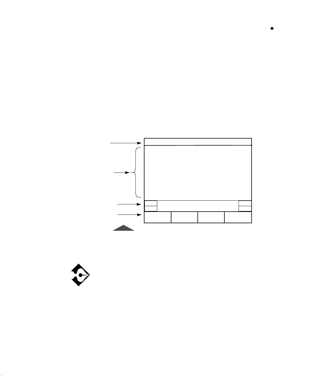
Test Configuration Examples
Chapter 5 — T1 Task Navigated Testing (TNT)
TNT Example
In this scenario, your customer has ordered T1 service, and you will
need to perform the final acceptance turnup procedures. After you
install the smart jack (NIU) at the customer premises, you must run a
straightaway (end-to-end) BER test with a CO technician to verify
service. This common test scenario requires two testers.
Because this is a common test application, you can use the TNT
mode.
1.
From the Home view, select T1 as the interface.
55
Title Bar
Selection
Area
Prompting
Area
Softkeys
1:1 Home
Interface: T1
Task: T1 BERT TURN-UP
Test: STRAIGHTAWAY
FUNC
MORE
T1 BERT
TURN-UP
Select Task To Be
Performed:
FT1 BERT
TURN-UP
T1/FT1 FR
TURN-UP
DDS BERT
TURN-UP
Figure 12 • Home View
2.
Select
Pressing the
MORE
those choices is
T1 BERT TURN-UP
key shows additional choices. One of
MANUAL SETUP
as the task.
. Manual Setup allows you to
set up your test using the Interface and Test Type views. See
“Setting Up Manual T1 Test” on page 62 for Manual Setup
instructions.
3.
Select
STRAIGHTAWAY
as the test.
4.
Press
SETUP
to access the TNT Setup view.
T-BERD 950 User’s Guide
Page 78
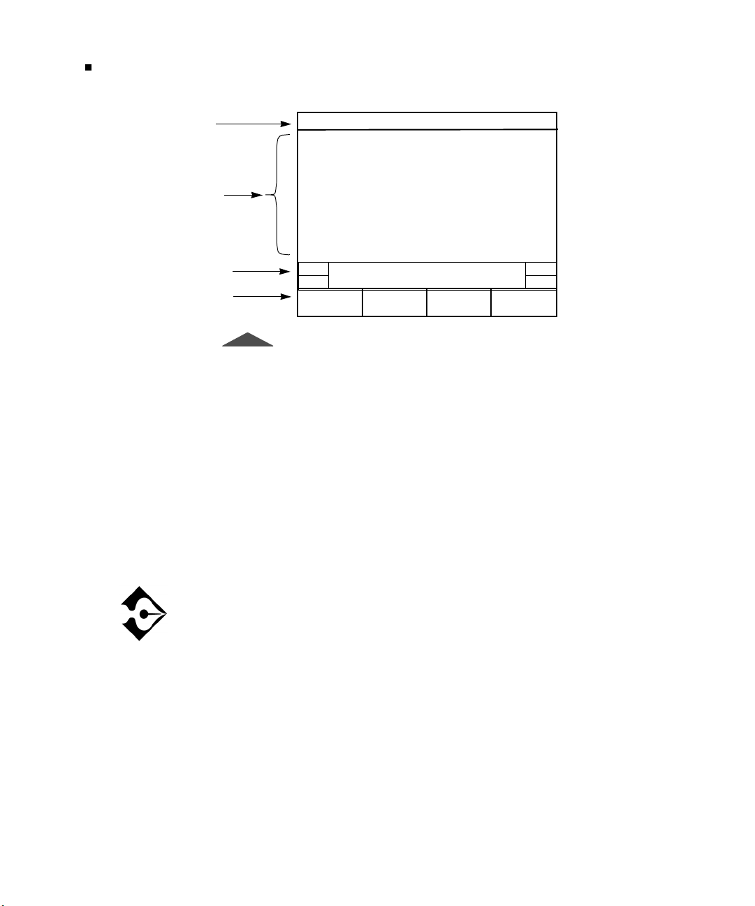
Test Configuration Examples
56
Chapter 5 — T1 Task Navigated Testing (TNT)
Title Bar
Selection
Area
Prompting
Area
Softkeys
3:3 TNT T1 STRAIGHTAWAY
Framing: AUTO
Line Coding: B8ZS
Tx Timing: INTERNAL
Loopcode: CSU
Bert Pattern: QRSS
FUNC
MORE
Figure 13 • TNT Setup View
5.
Select the framing.
The default setting is
framing on the line. Set the framing after the T-BERD 950
has made a determination.
6.
Select the appropriate line coding (
7.
Select the appropriate transmit timing (
default).
Select Framing:
SF SLC UNFRAME DESF
AUTO
framing, which will detect the
is the default).
B8ZS
INTERNAL
is the
T-BERD 950 User’s Guide
8.
Select the appropriate BERT pattern (
is the default).
QRSS
If you need to change any pre-set configurations, press
once to access the Manual Setup mode Interface view
SETUP
and again to access the Manual Setup mode Test Type view.
If you press
SETUP
a third time, the display returns to the
TNT Setup view.
9.
Connect to the Circuit. If you are performing a straightaway
BER test at the customer premises, you will most likely be
accessing the circuit at the 66 block, NIU, or DSX-1 patch
panel.
Page 79
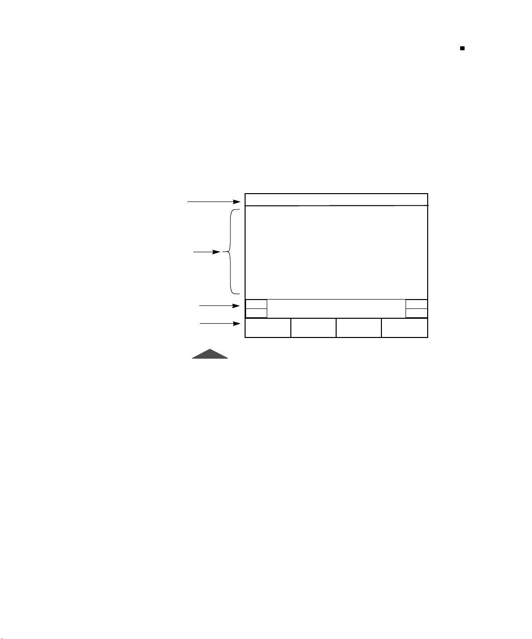
Test Configuration Examples
Chapter 5 — T1 Task Navigated Testing (TNT)
10.
Verify you have a T1 Signal, Frame Sync, and Pattern Sync
(the SIGNAL, FRAME SYNC and PATTERN SYNC LEDs
illuminate green). Both you and your test partner need to send
errors back and forth to validate your connection. Press
RESTART
11.
Press
As with the Setup views, press
to begin a new test.
RESULTS
to view TNT specific results (see Figure 14).
RESULTS
to cycle through all
eight categories in the Results view.
57
Title Bar
Selection
Area
Prompting
Area
Softkeys
8:8 TNT T1 Send Loopback(NI U)
BPVs N/A
Bit Errors N/A
Pat Slips N/A
Frm Errors N/A
Errored Sec N /A
CRC Errors N/A
Rx Freq, Hz N/A
R Lvl, dBdsx N/A
Figure 14 • TNT Results View
Manual Setup Example
Similar to the TNT scenario, you will need to perform a T1 turnup
with the additional requirements of performing an end-to-end BER
test, and sending an idle code and a Yellow Alarm. This is not the
typical testing scenario. Therefore, use Manual Setup mode.
Press HELP For Additional
Result Information.
PRINT
SCREEN
1.
From the Home view, select T1 as the
2.
3.
4.
Select
MANUAL SETUP
Select
BERT
Press the
as the
key to access the Manual Setup Interface
SETUP
Test
as the
.
view.
Task
Interface
.
.
T-BERD 950 User’s Guide
Page 80

Test Configuration Examples
58
Chapter 5 — T1 Task Navigated Testing (TNT)
5.
Select
TERMINATE
6.
Select the appropriate
7.
Select
FULL
8.
Select the appropriate
9.
Select
TERM
10.
Select
TERM
11.
Select
LINE
12.
Select the appropriate
In this testing scenario, set one test set to
the other to
A loopcode selection is not required because this is an
end-to-end test and you are not looping components.
13.
Set
Auto-Respond
14.
Select the appropriate
15.
Use the keypad to enter the
11111111
).
as the
as the
Payload
as the
as the
as the
Tx/Rx Pair
INTERNAL
to
Mode
Framing
.
Line Coding
Line Rx In
Equip Rx In
.
Tx Timing
.
OFF.
Line LBO
Idle Byte
.
(default is
(default is
.
.
(default is
if required.
value (default is
).
ESF
).
B8ZS
RECOVERED
RECOVERED
).
and
T-BERD 950 User’s Guide
16.
17.
18.
Select
Select
Press
as the
ON
DS1 Idle Tx
again to access the Manual Setup Test Type
SETUP
Yel l ow Alar m
to
to transmit a DS1 idle code.
ON
to transmit a yellow alarm.
view.
19.
Select the appropriate
20.
Select the appropriate
21.
Select the appropriate
22.
Connect to the Circuit. If you are performing a straightaway
Bert Pattern
Error Insert Type
Error Insert Rate
.
(default is
.
BER test at the customer premises, you will most likely be
accessing the circuit at the 66 block, NIU, or DSX-1 patch
panel.
LOGIC
).
Page 81

Using the Manual to Setup Configurations
Chapter 5 — T1 Task Navigated Testing (TNT)
Verify you have a T1 Signal, Frame Sync and Pattern Sync
(the SIGNAL, FRAME SYNC and PATTERN SYNC LEDs
illuminate green), and exchange errors with your test partner
to validate your connection.
23.
24.
25.
Press
Press
Press
RESTART
RESULTS
RESULTS
to begin a new test.
to show the Results Test Type Category view.
to cycle through the all seven result category
views, and check the results for which you are concerned
(i.e., BPVs, bit errors, CRC errors, simplex current, and
signal level).
Using the Manual to Setup Configurations
The remaining chapters are organized by interface and option. Each
chapter provides both TNT and Manual Setup information. Unless it
is related to a specific option (i.e., Frame Relay), the configuration is
described in the appropriate interface section. For example, even
though you can test the frame relay option with the T1 or DDS-LL
interface, it is only available if you have the option (regardless of the
interface). Therefore, all frame relay TNT scenarios are described in
the Frame Relay Option section. This same principle applies to the
Primary Rate ISDN Option as well.
59
In each option/interface chapter, the TNT tasks are described and the
tests within each task are presented in a table. This table explains the
specific test as is pertains to the associated task. Also provided in
these tables are the configurable parameters in the TNT Setup view
and the results in the TNT Results view. The TNT Setup parameter
defaults are listed in parentheses () beside the TNT Setup parameter.
Following the TNT descriptions are the Manual Setup parameter
descriptions for the Interface and Test Type views, in addition to
detailed results information by category. Because the setup
parameters and results for TNT are a subset of those for Manual
Setup, refer to the Manual Setup section for definitions of these items.
T-BERD 950 User’s Guide
Page 82

Using the Manual to Setup Configurations
60
Chapter 5 — T1 Task Navigated Testing (TNT)
T-BERD 950 User’s Guide
Page 83
Chapter
T1 Manual Test
6
his section describes the basic test setup for the T1 interface on the
T-BERD 950.
T
Setup
T-BERD 950 User’s Guide
Page 84
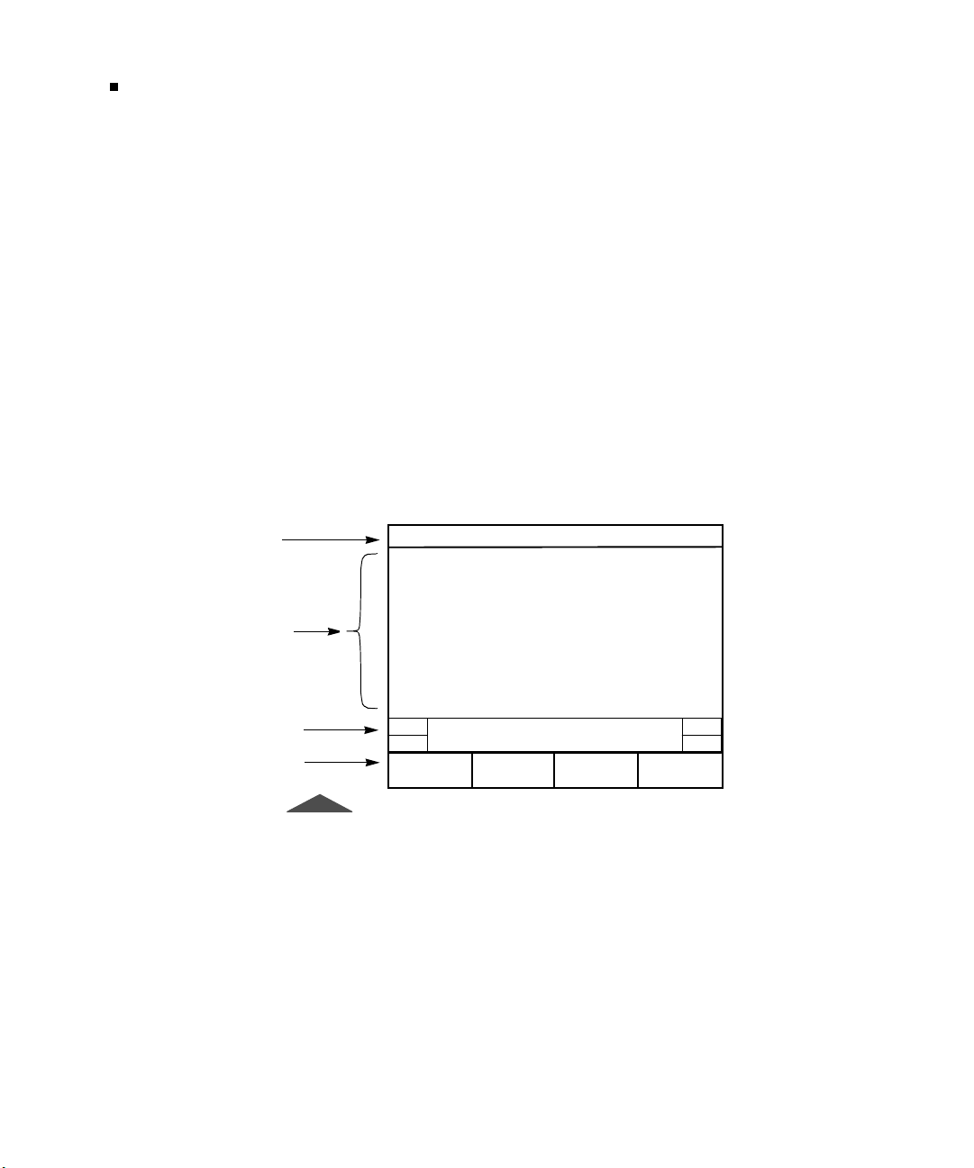
Setting Up Manual T1 Test
62
Chapter 6 — T1 Manual Test Setup
Setting Up Manual T1 Test
This section provides descriptions of the test setup parameters to
perform a variety of tests using the manual setups for the T1 interface.
Setting Up the Home View
Start with the Home view as shown in Figure 15.
1.
2.
3.
4.
Select the
Select the
Select the
Press the
T1 Interface
MANUAL SETUP Ta sk
BERT Test
SETUP
.
.
key.
.
Title Bar
Selection
Area
Prompting
Area
Softkeys
1:3 Home T 1-BERT
Interface: T1
Task: MANUAL SETUP
Test Type: BERT
FUNC Select Mode:
Figure 15 • Home View
Setting Up the T1 Interface View
The Setup Interface view is used to configure the T1 interface (see
Figure 16). Use the
area.
SCROLL
AUTO AUTO-RDELAY
and
keys to control this selection
PAG E
T-BERD 950 User’s Guide
Page 85
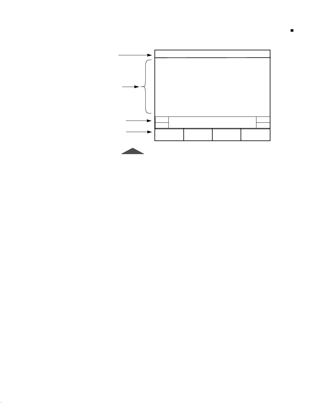
Setting Up Manual T1 Test
Chapter 6 — T1 Manual Test Setup
63
Title Bar
Selection
Area
Prompting
Area
Softkeys
1:2 Interface T1-BERT
Mode: TERMINATE
Framing: AUTO
Payload: FULL
Line Coding: B8ZS
Line Rx In: TERM
Equip Rx In: TERM
Tx Timing: INTERNAL
Loopcode: CSU
Auto Respond: ON
Line LBO: 0 db
Yellow Alarm: OFF
FUNC Sele ct Mode:
D&I MONITO R LLBTERMINATE
Figure 16 • T1 Setup Interface View
Using the Setup Interface view, select the parameters for your test:
— Enables selection of the operating mode (default is
Mode
TERMINATE
). The choices include the following:
TERMINATE
— Selects Terminate mode, both sides of a T1
path are separated, the input signal is terminated at the
receive side, and a totally independent signal is generated for
the output. Use this mode when the T-BERD 950 terminates
the line.
— Selects Drop and Insert mode, which enables the
D&I
analyzer to insert data onto specific channels from the T1 line
while leaving the other channels unaffected. Typically used at
a DSX-1 patch panel or similar T1 access point.
MONITOR
— Selects Monitor mode, which enables the
analyzer to measure signal parameters or monitor traffic from
a resistor-isolated DS1 monitor point, or bridge on to the line.
Use this mode to analyze live traffic without disrupting the
circuit. You can monitor one or two circuits at a time. BER
testing cannot be performed in Monitor mode.
— Selects Line Loop Back mode, which causes the
LLB
analyzer to loopback the received signal to the transmitter
without changing the signal. Not available when
VOICE
is the
selected test type.
T-BERD 950 User’s Guide
Page 86

Setting Up Manual T1 Test
64
Chapter 6 — T1 Manual Test Setup
Not all of the following selection lines are available in all
operating modes.
Framing
T1 signal (default is
— (all operating modes) Selects the framing format for the
ESF). Choices include:
— Enables transmission and analysis of T1 signals with
ESF
Extended SuperFrame (ESF) framing format.
Enables transmission and analysis of T1 signals with
SF —
SuperFrame (SF) framing format.
— Enables transmission and analysis of T1 signals with
SLC
SLC-96 framing.
UNFRAMED
— Enables data analysis on the full 1.544 Mbps
bandwidth of the T1 line. No framing bits are added during
transmission, and no data bits are stripped when received.
Not available in
type.
— Performs automatic Frame Search. The unit
AUTO
automatically configures the receivers and transmitters to the
incoming framed and unframed T1 signals. AUTO Framing
Searching appears on the RESULTS I and II display while
the unit attempts to identify the received framing mode. If
frame synchronization is received, the detected mode will be
printed in lowercase letters on the Setup view, as indicated in
Table 12.
Table 12 • AUTO Framing
mode or when
D&I
is the selected test
VOICE
T-BERD 950 User’s Guide
T1 Signal Format AUTO Mode Selection
D1D *sf
D2 *sf
D4 *sf
Page 87
Setting Up Manual T1 Test
Chapter 6 — T1 Manual Test Setup
Table 12 • AUTO Framing (Continued)
T1 Signal Format AUTO Mode Selection
ESF *esf
SLC *slc
Unframed unframed
AUTO mode is performed concurrently on the LINE and
EQUIPMENT receivers. The T-BERD 950 tries to
synchronize to the LINE input. If framing synchronization is
achieved, the green LINE Frame Sync LED illuminates; the
detected mode appears in lowercase letters; and the T-BERD
950 tries to synchronize to the same frame format with
EQUIPMENT. If EQUIPMENT frame format is not the same
as LINE, then the green EQUIPMENT Frame Sync does not
illuminate. Neither the LINE nor the EQUIPMENT frame
sync LEDs will be illuminated in this scenario.
65
AUTO -R
— Performs Automatic Restart Frame Search. The
unit operates in the manner described in AUTO; however, it
automatically searches for frame synchronization upon the
loss of frame synchronization or when signal is lost and
reacquired (i.e., when the Frame Sync LED is no longer
illuminated).
Auto-R this mode should not be selected when performing
long-term, unattended testing, because valid testing results
will be cleared each time frame sync is reacquired.
Payload
circuit type to be tested (default is
— (not available for VOICE testing) Enables selection of the
). Choices include:
FULL
— (not available in D&I operating mode) Configures
FULL
the analyzer to transmit and receive data at the full T1 rate.
T-BERD 950 User’s Guide
Page 88

Setting Up Manual T1 Test
66
Chapter 6 — T1 Manual Test Setup
— Selects the channel bandwidth for Nx56 kbps data
Nx56
analysis. This selection line shows only the number of
channels currently selected. Selecting Nx56 accesses the
Channels
Nx64
selection line.
— Selects the channel bandwidth for Nx64 kbps data
analysis. This selection line shows only the number of
channels currently selected. Selecting Nx64 accesses the
Channels
selection line.
Channels
— (Nx54 and Nx64) Selects the channel to
test. Use the softkeys to select the channel.
— Selects DDS over T1 analysis and enables the
DDS
selection of an individual T1 (DS0) channel to be tested.
Channel
Use the
— Selects a specific DS0 channel to be tested.
INCREASE VALUE
or
DECREASE VALUE
softkeys to set the channel.
— Selects the unframed channel format and data
Rate
transmission subrate over the DS0 64 kbps channel
(default is
CLEAR CHANNEL
CLEAR CHANNEL
). Choices include:
— Select to test DS0-A
formatted DDS data at 64 kbps. Uses entire DS0
bandwidth.
DS0A56
— Select to test DS0-A formatted DDS
data at 56 kbps. Uses the entire DS0 bandwidth,
except bit 8, which is controlled by the analyzer
and distinguishes customer data from network
control information.
DS0A9.6
— Select to test DS0A formatted DDS
data at 9.6 kbps. Copies all eight bits of the
DS0A9.6 bandwidth five times into the selected 64
kbps channel.
DS0A4.8
— Select to test DS0A formatted DDS
data at 4.8 kbps. Copies all eight bits of the DS04.8
bandwidth 10 times into the selected 64 kbps
channel.
T-BERD 950 User’s Guide
DS0A2.4
— Select to test DS0A formatted DDS
data at 2.4 kbps. Copies all eight bits of the DS02.4
bandwidth 20 times into the selected 64 kbps
channel.
Page 89

Setting Up Manual T1 Test
Chapter 6 — T1 Manual Test Setup
67
Line Coding
coding for the transmitted data (default is
— (all operating modes) Enables selection of the line
). Choices include:
B8ZS
— Selects Alternate Mark Inversion (AMI) coding.
AMI
— Selects Bipolar with 8 Zero Substitution (B8ZS)
B8ZS
coding.
Line Rx In
receiver input impedance and signal conditioning (default is
— (all operating modes) Enables selection of the LINE
TERM
Choices include:
— Select when the T-BERD 950 terminates the line.
TERM
Provides 100
DSX MON
Ω ±
5% resistive termination.
— Select when the T-BERD 950 connects to the
circuit via the DSX-1 patch panel or similar access point.
Provides resistive compensation for signals with +6.0 dBdsx
to -35 dBdsx of cable loss at 772 kHz, and can accommodate
signals resistively attenuated from +0.0 dBdsx through -26.0
dBdsx.
BRIDGE
circuit. Provides greater than 1000
Equip Rx In
— Select when the T-BERD 950 bridges onto the
Ω
resistive termination.
— (all operating modes) Enables selection of the
EQUIPMENT receiver input impedance and signal conditioning
(default is
DSX-MON
). Choices include:
).
— Select when the T-BERD 950 terminates the line.
TERM
Provides 100
DSX MON
Ω ±5%
resistive termination.
— Select when the T-BERD 950 connects to the
circuit via the DSX-1 patch panel or similar access point.
Provides resistive compensation for signals with +6.0 dBdsx
to -35 dBdsx of cable loss at 772 kHz, and can accommodate
signals resistively attenuated from +0.0 dBdsx through -26.0
dBdsx.
BRIDGE
— Select when the T-BERD 950 bridges onto the
circuit. Provides greater than 1000
Insert Side
— (D&I operating mode only) Enables selection of the T1
interface that data is inserted on (default is
LINE Tx
or
EQUIPMENT Tx
— Selects the T1 LINE or
EQUIPMENT transmitter.
Ω
resistive termination.
LINE Tx
). Choices include:
T-BERD 950 User’s Guide
Page 90

Setting Up Manual T1 Test
68
Chapter 6 — T1 Manual Test Setup
Insert Payload
on or off (default is
— (D&I operating mode only) Turns payload insertion
).
OFF
Whenever any of the following parameters are changed,
Insert Payload
,
Equip Rx In, Payload, Insert Side, Line LBO, Equip LBO
Rx In
Channels, Tx Timing
mode is selected,
Tx/Rx Pair
of the receiver and transmitter pair (default is
is reset to
OFF: Mode, Framing, Line Coding, Line
,
, and
Test Type
Insert Payload
. In addition, each time
is reset to
OFF
.
— (TERMINATE operating mode only) Enables selection
). Choices include:
LINE
LINE
or
EQUIPMENT
— Selects the LINE or EQUIPMENT
receiver and transmitter pair.
Tx Timing
— (TERMINATE operating mode only) Enables selection
of the signal timing source for each of the T1 transmit channels, LINE
and EQUIPMENT (default is
RECOVERED
— Selects the receiver channel clock as the
RECOVERED
). Choices include:
timing source for the transmitter. Timing is derived from the
incoming (Rx) signal.
INTERNAL
— Selects the internal crystal oscillator as the
timing source for the transmitter.
D&I
T-BERD 950 User’s Guide
Setting DDS Loop Codes
Loop Code Type
either latching or alternating loop codes (default is
Choices include:
LATCHING
all eight bits of a DS0 are used to transmit network control
codes. The success or failure of latching loop code operation
will be reported at the end of each latching loop up or loop
down operation on the Two-Line Display.
ALTERNATING
latching) loop code where the payload data is intermixed
every other byte with the loop code. The success or failure of
an alternating loop code operation shall be reported at the end
of each loop up or loop down.
— (DDS payload only) Enables the selection of
— Enables selection of a latching loop code where
— Enables selection of an alternating (non-
LATCHING
).
Page 91

Setting Up Manual T1 Test
Chapter 6 — T1 Manual Test Setup
An “n” signifies a “don’t care” value an “S” signifies the
subrate framing bit; “1” when transmitting/receiving an idle
code of a 56 kbps DS0A signal; “0” when transmitting/
receiving a DSU loopback of a 56 kbps DS0A signal; or
“don’t care” for all other transmitted/received DS0A signals.
69
Loop Code
— (TERMINATE operating mode only) Enables selection
of the loop code sequence transmitted through the active channels or
through the ESF Data Link when the
are pressed (default is
— (DDS ALTERNATING or LATCHING loop code type
CSU
). Choices for DDS include:
CSU
LOOP UP
and
LOOP DOWN
keys
only) Selects the loop code for a Channel Service Unit.
Alternating loop code: S0101000. Latching loop code:
N0110001.
CSU+R
— (ALTERNATING loop code type only) Selects the
alternating loop code for a Channel Service Unit with one
repeater between the CSU and the analyzer. Alternating loop
code: S0101000.
When a repeater is on the span, the
CSU+R
loops up the
repeater with the CSU loop up sequence. The analyzer loops
down the repeater, allowing the following transmission to
pass through. The CSU then loops up with the standard
alternating loop back activation.
CSU+2R
— (ALTERNATING loop code type only) Selects
alternating loop code for a Channel Service Unit with two
repeaters between the CSU and the analyzer. Alternating loop
code: S0101000.
When two repeaters are on the span, the sequence for the
(
CSU+2R
) loop code is the same as the CSU+R, except, after
the second loop up sequence is transmitted, a second loop
down sequence is transmitted, followed by a third loopback
activation sequence.
1ST RPTR
— (ALTERNATING loop code type only) Selects
First 56 kbps repeater. Alternating loop code: S0101000.
2ND RPTR
— (ALTERNATING loop code type only) Selects
Second 56 kbps repeater. Alternating loop code: S0101000.
T-BERD 950 User’s Guide
Page 92

Setting Up Manual T1 Test
70
Chapter 6 — T1 Manual Test Setup
— (ALTERNATING or LATCHING loop code type only)
OCU
Selects Office Channel Unit loop code. Alternating loop
code: S0101010. Latching loop code: N1010101.
The
OCU+HL96
code loops up with the OCU sequence. The analyzer
loops down the HL96NY, allowing the following transmissions to
pass through. The OCU is then looped up with the standard
alternating loopback activation sequence.
OCU+HL96
— (ALTERNATING loop code type only) Selects
Office Channel Unit behind a HL96NY. Alternating loop
code: S0101010.
HL96NY
— (ALTERNATING loop code type only) Selects
HL96NY Office Channel Unit. Alternating loop code:
S0101010.
— (LATCHING loop code type only) Selects LIN Side
LSI
Interface. Latching loop code: N1000111.
— (LATCHING loop code type only) Selects Network
NEI
Element Interface. Latching loop code: N1000001.
The DS0-DP loop code loops up or down any DS0 data port
within a series of eight DS0 data ports. At the completion of
the loop, feedback is read from the looped DS0 data port that
determines if the DS0 data port is configured from the LINE
side or drop side.
DS0-DP
— (LATCHING loop code type only) Selects DS0-
Data Port latching loop code: N0000101.
Location
include:
— (ALTERNATING or LATCHING loop code type only)
DSU
— Selects the data port location. Choices
1, 2, 3, 4, 5, 6, 7
, or 8.
Selects Data Service Unit loop code. Alternating loop code:
S0101100. Latching loop code: N1110111.
T-BERD 950 User’s Guide
Setting T1 Loop Codes
Loop Code
of the loop code sequence transmitted through the active channels or
through the ESF Data Link when the
are pressed (default is
— (TERMINATE operating mode only) Enables selection
). Choices include:
CSU
LOOP UP
and
LOOP DOWN
keys
Page 93

Setting Up Manual T1 Test
Chapter 6 — T1 Manual Test Setup
— (not available for DDS) Selects repeating inband
CSU
71
Channel Service Unit (CSU) loop codes: loop up = 10000
and loop down = 100. These loop codes are valid in Full T1,
Fractional T1, and all framing modes.
— (not available for DDS) Enables selection of network
NIU
interface (or smart jack) inband repeating codes.
Table 13 • Repeater Typ e
NIU Type
— Selection line appears, allowing selection
of the Facility Type codes listed below.
— Selects Facility Type 1 network interface
FAC 1
(or smart jack) inband repeating 4-bit loop codes:
loop up = 1100 and loop down = 1110. These loop
codes are valid in Full T1, Fractional T1, and all
framing modes.
— Selects Facility Type 2 network interface
FAC 2
(or smart jack) inband repeating 5-bit loop codes:
loop up = 11000 and loop down = 11100. These
loop codes are valid in Full T1, Fractional T1, and
all framing modes.
— Selects Facility Type 3 network interface
FAC 3
(or smart jack) inband repeating 6-bit loop codes:
loop up = 100000 and loop down = 100. These
loop codes are valid in Full T1, Fractional T1, and
all framing modes.
REPEATER
— (FULL payload only) Selects repeater loop
codes sent over the T1 interface.
Repeater Type
— Selects Repeater type (see Table 13).
Central Office Repeaters Line Repeaters
Teltrend 7231LP/LW IOR Teltrend 7239LP/LW ILR
Teltrend 9132LP/LW IHR WSTL 315056 ILR A/B
WSTL 313056 IOR A/B WSTL 315056 ILR C..
WSTL 313056 IOR C.. WSTL 315156 ILR
WSTL 313080 IOR WSTL 313080 ILR
T-BERD 950 User’s Guide
Page 94

Setting Up Manual T1 Test
72
Chapter 6 — T1 Manual Test Setup
Table 13 • Repeater Type (Continued)
Central Office Repeaters Line Repeaters
WSTL315080 ILR
WSTL 315081 ILR
XEL 7853-200 ILR
— (REPEATER loop code only) Selects
CMD
commands to configure the repeater for testing see
“Setting T1 Loop Codes” on page 70. Based on the
repeater selected, the choices dynamically appear for
selection using the softkeys.
TIMEOUT DISABLE
— Disables the loopback, time-
out function of the repeater.
LOOPBACK QUERY
— Returns address of the
repeater that is in loopback.
POWER QUERY
— Returns address of the repeater
that is currently looping back the power.
ISSUES QUERY
— Returns the issue (revision) of
the repeater.
POWER DOWN/POWER UP
and the IOR accept
POWER DOWN
— The Teltrend IHR
commands
because both are capable of supplying power to the
span. When
POWER DOWN
command is set, the
command is received and turns the power off the
span. As long as the repeater is receiving this
Power Down sequence command, it will continue
to power down. However, when the command is no
longer being received (using
POWER UP
), the
power is then restored. This can take up to 5
seconds. This function is typically used to reset the
line, particularly if a repeater in loopback cannot
be looped down via commands.
SEQ LOOPBACK
— (REPEATER COMMANDS
only) Loops up or down, T1 line repeaters on the
span in sequence, starting with the repeater nearest
the T-BERD 950, and proceeds down the span,
regardless of the repeater’s address. Pressing
SEQ
T-BERD 950 User’s Guide
Page 95

Setting Up Manual T1 Test
Chapter 6 — T1 Manual Test Setup
73
LOOPBACK
transmits the sequential loopback code.
The first repeater on the span will loop up, return
its address, then loop down. This loopback
procedure continues for each repeater on the span.
Table 14 lists the command sets and addresses for the repeater type.
Table 14 • Commands and Addresses for Repeater s
Command
Set
1 — Teltrend 7231LP/LW IOR
2 up to 20 Teltrend 7239LP/LW ILR
3 up to 1999 Westell 3130-80 IOR
4 up to 1999 Westell 3150-80 ILR
5 up to 20 Westell 3150-56 ILR
Address Repeater Type
— Teltrend 9132LP/LW IHR
up to 2 Westell 3130-56 IOR
up to 1999 Westell 3150-81 ILR
up to 20 Westell 3151-56 ILR
Table 15 shows the commands available for each command set.
Table 15 • Command Se ts
Command Set 1 Set 2 Set 3 Set 4 Set 5
Timeout Disable
Loopback Query
Power Query
Issues Query
✔ ✔ ✔ ✔ ✔
✔ ✔ ✔ ✔ ✔
✔ ✔ ✔
✔ ✔
T-BERD 950 User’s Guide
Page 96
Setting Up Manual T1 Test
74
Chapter 6 — T1 Manual Test Setup
Table 15 • Command Sets (Continued)
Command Set 1 Set 2 Set 3 Set 4 Set 5
Power Up
Power Down
Sequential Loopback
✔ ✔
✔ ✔
✔ ✔
— (FULL payload only) High bit-rate Digital
HDSL
Subscriber Line. Selects HDSL loop code transmitted over
the HDSL circuit.
HDSL Type
Table 16 • HDSL Equipment
HDSL Central Office Cards Repeaters/Doublers Customer Premises Cards
Adtran HTU-C Adtran HRE Adtran HTU-R
PairGain HLU PairGain HDU PairGain HRU
Adtran Codes
STANDARD
softkeys available). If
CMDS
softkey becomes available. See “Using HDSL and
— Selects HDSL type (see Table 16).
— (HDSL loop code only) Choices include:
and
ABBREVIATED
STANDARD
. Default is
is selected, the
ABBREVIATED
Repeater Commands Softkeys” on page 75.
(no
REPEATER
T-BERD 950 User’s Guide
PairGain Codes
and
A2LB
available). If
— (HDSL loop code only) Choices include:
GENERIC
A2LB
. Default is
GENERIC
is selected, the
(no softkeys
REPEATER CMDS
softkey
becomes available. See “Using HDSL and Repeater
Commands Softkeys” on page 75.
Origin of Test
— (REPEATER and select HDSL loop codes
only) Selects point of origin of the test. Choices include:
CENTRAL OFFICE
CENTRAL OFFICE
or
CUSTOMER PREM
.
. The default is
Page 97

Setting Up Manual T1 Test
Chapter 6 — T1 Manual Test Setup
75
Address
— (HDSL loop codes only) Set the address of the HDSL
equipment.
Using HDSL and Repeater Commands Softkeys
To access the
control. Press the
EN D A R M , D I S A R M, ADDR UP,
REPEATER CMDS
REPEATER CMDS
— Transmits an arming code on the span when testing
ARM
from the Central Office toward the NIU to prepare the span
for receipt of loop up or loop down codes.
NEAR END ARM
— Transmits a near-end arming code on the
span when testing from the NIU toward the Central Office
(CO) to prepare the span for receipt of loop up or loop down
codes.
DISARM
— Transmits a disarming code on the span to disarm
the span when testing is completed.
ADDR UP / ADDR DOWN —
one) the repeater address from the current address.
PROGRAMMABLE
— Selects user-programmable inband loop codes
(3 to 16 bit loop up and loop down codes), the left-most bit of each
code string is transmitted first. These loop codes are valid in Full T1,
Fractional T1, and all framing modes. When selected, the following
selection lines are available:
Prog Set #
— Allows you to program and access up to 10
user-programmable loop up and loop down codes. Each set
contains its own 16 bit loop up code and loop down code. You
can label each of the user-programmable codes
(n)
and
Loop Down Code (n)
See “Editing User-Programmable Fields” on page 77 for
details on editing this field.
softkey, press
FUNCTION
softkey to access to
and
ADDR DWN
softkeys.
Increments or decrements (by
with alphanumeric characters.
softkey
ARM, NEAR
Loop Up Code
Loop Up Code (n)
the loop up code (default is
— Enables setting the binary value of
). The left and right
10000
arrow keys on the keypad are used to select the
individual bit to be set, and the zero (
) or one (1) key
0
on the keypad is used to set the bit value.
T-BERD 950 User’s Guide
Page 98

Setting Up Manual T1 Test
76
Chapter 6 — T1 Manual Test Setup
Loop Down Code (n)
of the loop down code (default is
— Enables setting the binary value
). The left and
100
right arrow keys on the keypad are used to select the
individual bit to be set, and the zero (
) or one (1) key
0
on the keypad is used to set the bit value.
— (not available when DDS loop code type is ALTERNATING)
V. 5 4
Selects inband loop code transmitted over a Fractional T1 bandwidth.
In
mode, the only loop code responded to is V.54.
D&I
DATALINK
— (ESF framing only) A communications connection used
to transmit data. These loop codes comply with the ANSI T1.403
(‘95) specifications Datalink Type.
DL-LLB
— Selects out-of-band ESF Data Link Line
Loopback codes. The loop codes include: loop up = 1111
1111 0111 0000 and loop down = 1111 1111 0001 1100; the
left-most bit of each code string is transmitted first. These
loop codes are valid in Full T1 or Fractional T1 when ESF
framing is selected.
DL-PLB
— Selects out-of-band ESF Data Link Payload
Loopback codes. The loop codes include: loop up = 1111
1111 0010 1000 and loop down = 1111 1111 0100 1100; the
left-most bit of each code string is transmitted first. These
loop codes are valid in Full T1 or Fractional T1 when ESF
framing is selected.
T-BERD 950 User’s Guide
DL-NET
— Selects out-of-band ESF Data Link Network
Loopback codes. The loop codes include: loop up = 0000
0000 0100 1000 and loop down = 0000 0000 0010 0100; the
left-most bit of each code string is transmitted first. The loop
codes are valid in Full T1 or Fractional T1 when ESF framing
is selected.
Auto-Respond
Enables Auto-Respond (to loop codes) to be turned
(default is
— (TERMINATE and D&I operating modes only)
or
ON
). When Auto-Respond is set to
OFF
the analyzer is
ON,
OFF
configured for automatic loop code response and the response status
Page 99

Setting Up Manual T1 Test
Chapter 6 — T1 Manual Test Setup
77
will appear on the Two-Line Display. The applicability of the loop
code and the mode (Fractional T1 or Full T1) determine what is
actually looped back (Line, Payload or Fractional Payload).
— Turns Auto-Respond to selected loop codes on.
ON
— Turns Auto-Respond to selected loop codes off.
OFF
Editing User-Programmable Fields
This feature allows you to enter any combination of alphanumeric
characters to label your programmable loop codes for testing.
1.
2.
Select the
EDIT
Press the
Loop Up Code (n) or Loop Down Code (n)
softkey appears.
softkey and a popup window appears.
EDIT
Additional softkeys appear.
— Clears the field.
Clear
— Places the cursor at the beginning of the
Home
string.
— Places the cursor at the end of the string.
End
field. The
3.
Press the 1 through 9, or 0 key on keypad to select a character
set. The assigned values for that key are shown in the popup
window.
4.
Press the corresponding number for the character you want to
place into the user data information. Press 0 to add spaces if
needed.
5.
Repeat steps 3 and 4 until your loop code label is complete.
6.
Press
SCROLL
when finished to move to the next selection
line.
Line LBO
— (TERMINATE [with Tx/Rx Pair=LINE] and D&I
operating modes only) Enables emulation of four different cable
losses for the T1 LINE output signal level (default is
0 dB
). The
selected cable loss affects the transmit data only at the connectors.
Choices include:
T-BERD 950 User’s Guide
Page 100

Setting Up Manual T1 Test
78
Chapter 6 — T1 Manual Test Setup
— Sets the output (Tx) to the DSX level with no line
0 dB
build-out (0 dB attenuation).
-7.5 dB
— Provides -7.5 dB line build-out, attenuating the
output with 7.5 dB of simulated cable loss.
— Provides -15 dB line build-out, attenuating the
-15 dB
output with 15 dB of simulated cable loss.
-22.5 dB
— Provides -22.5 dB line build-out, attenuating the
output with 22.5 dB of simulated cable loss.
Equip LBO
— (TERMINATE [with Tx/Rx Pair=EQUIP] and D&I
operating modes only) Enables emulation of four different cable
losses for the T1 EQUIPMENT output signal level (default is
0 dB
).
The selected cable loss affects the transmit data only at the
connectors. Choices include:
— Sets the output (Tx) to the DSX level with no line
0 dB
build-out (0 dB attenuation).
-7.5 dB
— Provides -7.5 dB line build-out, attenuating the
output with 7.5 dB of simulated cable loss.
— Provides -15 dB line build-out, attenuating the
-15 dB
output with 15 dB of simulated cable loss.
-22.5 dB
— Provides -22.5 dB line build-out, attenuating the
output with 22.5 dB of simulated cable loss.
Idle Byte
— (TERMINATE and D&I operating modes only) Enables
setting the binary value of the idle byte to be inserted on inactive
channels (default is
11111111
). The left and right arrow keys on the
keypad are used to select the individual bit to be set, and the zero (0)
or one (1) key on the keypad is used to set the bit value. The idle byte
is inserted in the opposite direction of the inserted payload in D&I
mode to block looped test patterns.
T-BERD 950 User’s Guide
Yellow Alarm
— (TERMINATE and D&I operating modes only)
Enables selection of yellow alarm (default is
— Automatically transmits yellow alarm upon Loss of
Auto
Signal.
— Turns on transmission of yellow alarm.
ON
— Turns off transmission of yellow alarm.
OFF
). Choices include:
OFF
 Loading...