

Page 1

Acterna FST-2802 TestPad
Gigabit Ethernet Services Module
User’s Guide
Page 2

Page 3

Acterna FST-2802 TestPad
Gigabit Ethernet Services Module
User’s Guide
Page 4

Page 5

Notice
Every effort was made to ensure that the information in this document
was accurate at the time of printing. However, information is subject to
change without notice, and Acterna reserves the right to provide an
addendum to this document with information not available at the time
that this document was created.
Copyright
Trademarks
© Copyright 2003 Acterna, LLC. All rights reserved. Acterna, The
Keepers of Communications, and its logo are trademarks of Acterna,
LLC. All other trademarks and registered trademarks are the property
of their respective owners. No part of this guide may be reproduced or
transmitted electronically or otherwise without written permission of
the publisher.
Acrobat Reader is a registered trademark of Adobe Systems Incorporated in the United States and/or other countries.
Acterna and FST-2802 are trademarks or registered trademarks of
Acterna in the United States and/or other countries.
HyperTerminal is a registered trademark of Hilgraeve Inc. in the United
States and/or other countries.
Microsoft, Microsoft Internet Explorer, On-screen Keyboard, Windows,
Windows CE, Windows NT, and Windows XP are either trademarks or
registered trademarks of Microsoft Corporation in the United States
and/or other countries.
Specifications, terms, and conditions are subject to change without
notice. All trademarks and registered trademarks are the property of
their respective companies.
Ordering information
This guide is a product of Acterna's Technical Information Development Department, issued as part of the Acterna FST-2802 Gigabit
Ethernet Services Module. The ordering number for a published guide
is ML-2802-1103.
FST-2802 TestPad User’s Guide Revision A v
Page 6

Federal
Communications
Commission (FCC)
Notice
This product was tested and found to comply with the limits for a Class
A digital device, pursuant to Part 15 of the FCC Rules. These limits are
designed to provide reasonable protection against harmful interference when the equipment is operated in a commercial environment.
This product generates, uses, and can radiate radio frequency energy
and, if not installed and used in accordance with the instruction
manual, may cause harmful interference to radio communications.
Operation of this product in a residential area is likely to cause harmful
interference, in which case you will be required to correct the interference at your own expense.
This device complies with part 15 of the FCC Rules. Operation is
subject to the following two conditions: (1) This device may not cause
harmful interference, and (2) This device must accept any interference
received including interference that may cause undesired operation.
The authority to operate this product is conditioned by the requirements that no modifications be made to the equipment unless the
changes or modifications are expressly approved by Acterna.
Industry Canada
Requirements
EMC Directive
Compliance
vi FST-2802 TestPad User’s Guide Revision A
This Class A digital apparatus complies with Canadian ICES-003.
Cet appareil numérique de la classe A est conforme à la norme NMB003 du Canada.
This product was tested and conforms to the EMC Directive, 89/336/
EEC as amended by 92/31/EEC and 93/68/EEC for electromagnetic
compatibility. A copy of the Declaration of Conformity is provided with
this manual.
If you purchase the 2802-FE to perform 10/100 Ethernet testing, you
must use the shielded twisted pair cable (STP) provided to maintain
CE compliance.
Warning: This is a class A product. In a domestic environment this
product may cause radio interference in which case the user may be
required to take adequate measures.
Page 7

Low Voltage Directive
Compliance
This product was tested and conforms to the Low Voltage Directive,
73/23/EEC as amended by 93/68/EEC. Conformity with this directive
is based upon compliance with the harmonized safety standard,
EN60950. A copy of the Declaration of Conformity is provided with this
manual.
FST-2802 TestPad User’s Guide Revision A vii
Page 8
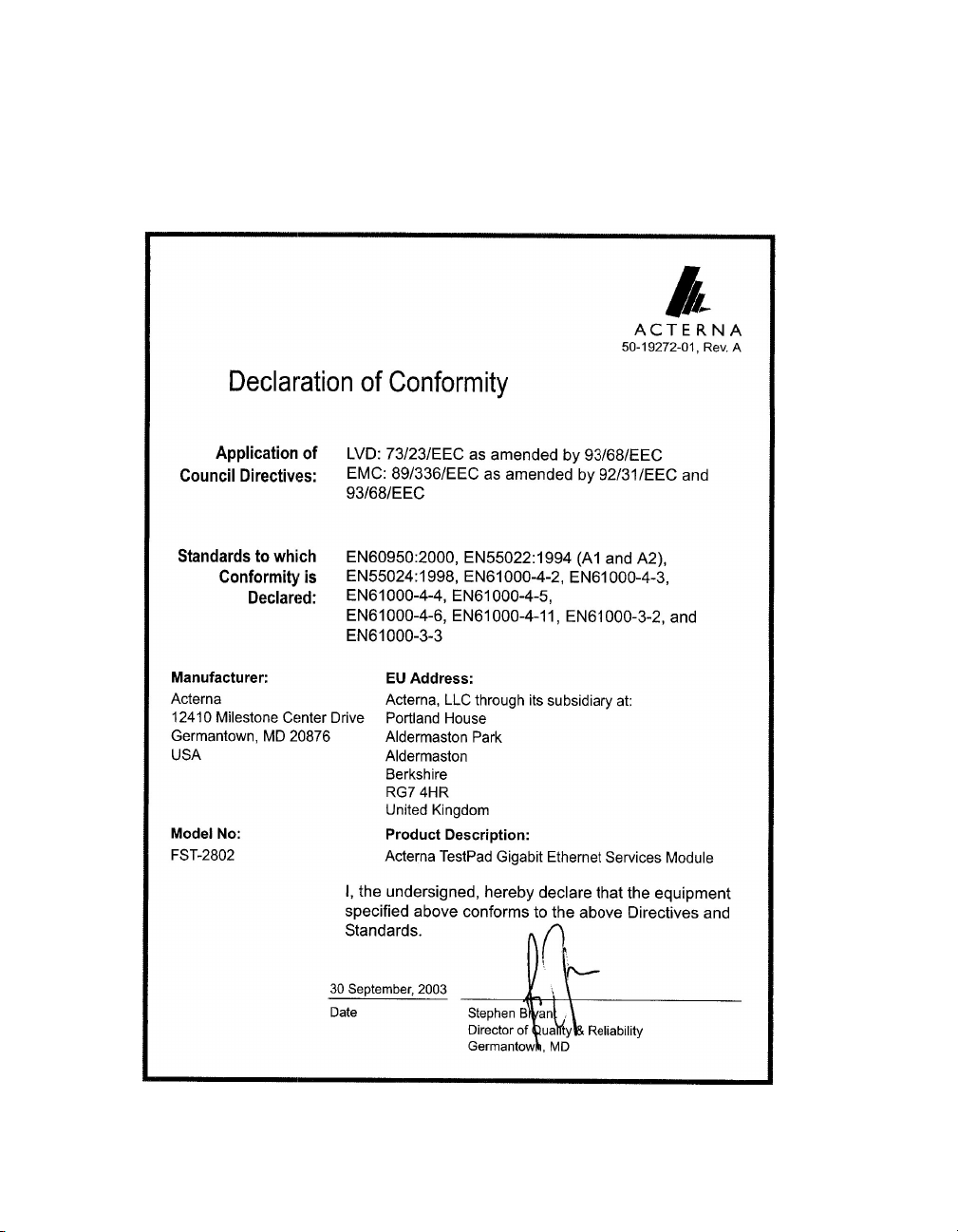
Declaration of
conformity
viii FST-2802 TestPad User’s Guide Revision A
Page 9

Important Safety Instructions
The following table defines safety terms. Failure to observe these
precautions while using the FST-2802, violates the intended use of this
product.
Safety definitions
Term Description
DANGER Indicates an imminently hazardous situation which, if
not avoided, will result in death or serious injury.
WARNING Indicates a potentially hazardous situation which, if
not avoided, could result in death or serious injury.
CAUTION Indicates a potentially hazardous situation which, if
not avoided, may result in minor or moderate injury. It
may also be used to alert against unsafe practices.
When using this product, always follow basic safety precautions to
reduce the risk of fire, shock, and injury to persons. Basic safety
precautions are as follows:
1 Read and follow all warning notices and instructions marked on
the product and included in the manual.
2 Use only the AC Adapter/Charger supplied with the product.
3 Do not use AC Adapter/Charger outdoors or in wet or damp loca-
tions.
4 Connect the AC Adapter/Charger to the correct mains voltage, as
indicated on the ratings label.
5 Do not allow anything to rest on the power cord, and do not locate
the product where people can walk on the power cord.
6 Avoid using this product during an electrical storm. There may be
a remote risk of electric shock from lightning.
7 Do not use this product in the vicinity of a gas leak or in any explo-
sive environment.
8 Do not attempt to service this product yourself, as opening or
removing covers may expose you to dangerous, high voltage
points and other hazards. Contact qualified service personnel for
all service.
FST-2802 TestPad User’s Guide Revision A ix
Page 10
9 CAUTION: Danger of explosion if battery is incorrectly replaced.
Replace only with (part number 11-18066). Dispose of used
batteries according to the manufacturer's instructions.
10 CAUTION: Use of controls or adjustments or performance of
procedures other than those specified herein may result in
hazardous radiation exposure.
11 CAUTION: The FST-2802 is a Class 1 laser product.
Save these instructions
Symbols
The following safety symbol is used on the FST-2802. All safety
precautions must be observed when operating, servicing, or repairing
the FST-2802. Failure to comply with the following safety precautions
or with hazard cautions and warnings used throughout this manual
violates the intended use of this instrument.
GENERAL HAZARD
This icon represents a general warning or caution.
x FST-2802 TestPad User’s Guide Revision A
Page 11

Contents
About This Guide xxi
Purpose and scope . . . . . . . . . . . . . . . . . . . . . . . . . . . . . . . . . . . xxii
Assumptions . . . . . . . . . . . . . . . . . . . . . . . . . . . . . . . . . . . . . . . . xxii
Related information . . . . . . . . . . . . . . . . . . . . . . . . . . . . . . . . . . xxii
Technical assistance. . . . . . . . . . . . . . . . . . . . . . . . . . . . . . . . . . xxiii
Conventions . . . . . . . . . . . . . . . . . . . . . . . . . . . . . . . . . . . . . . . . xxiv
Chapter 1 FST-2802 TestPad Overview 1
About the FST-2802 TestPad . . . . . . . . . . . . . . . . . . . . . . . . . . . . . 2
What’s new. . . . . . . . . . . . . . . . . . . . . . . . . . . . . . . . . . . . . . . . . . . . 2
Features and capabilities . . . . . . . . . . . . . . . . . . . . . . . . . . . . . . . . 3
Ethernet features . . . . . . . . . . . . . . . . . . . . . . . . . . . . . . . . . . . . 4
Fibre Channel features . . . . . . . . . . . . . . . . . . . . . . . . . . . . . . . . 5
FST-2000 TestPad features . . . . . . . . . . . . . . . . . . . . . . . . . . . . 5
Configurations and options . . . . . . . . . . . . . . . . . . . . . . . . . . . . . . 6
FST-2802 options . . . . . . . . . . . . . . . . . . . . . . . . . . . . . . . . . . . . 7
FST-2000 TestPad options . . . . . . . . . . . . . . . . . . . . . . . . . . . . . 8
Accessories . . . . . . . . . . . . . . . . . . . . . . . . . . . . . . . . . . . . . . . . . . . 8
GBIC accessories . . . . . . . . . . . . . . . . . . . . . . . . . . . . . . . . . . . . 9
Connectivity accessories . . . . . . . . . . . . . . . . . . . . . . . . . . . . . 12
Print accessories . . . . . . . . . . . . . . . . . . . . . . . . . . . . . . . . . . . 14
Additional accessories . . . . . . . . . . . . . . . . . . . . . . . . . . . . . . . 15
FST-2802 TestPad User’s Guide Revision A xi
Page 12

Contents
Exploring the FST-2802. . . . . . . . . . . . . . . . . . . . . . . . . . . . . . . . . 15
Top panel. . . . . . . . . . . . . . . . . . . . . . . . . . . . . . . . . . . . . . . . . . 16
USB/Serial port . . . . . . . . . . . . . . . . . . . . . . . . . . . . . . . . . . 17
PCMCIA card slots . . . . . . . . . . . . . . . . . . . . . . . . . . . . . . . 17
Bottom panel . . . . . . . . . . . . . . . . . . . . . . . . . . . . . . . . . . . . . . . 18
Front panel . . . . . . . . . . . . . . . . . . . . . . . . . . . . . . . . . . . . . . . . 19
LED display panel . . . . . . . . . . . . . . . . . . . . . . . . . . . . . . . . . . . 20
Powering the TestPad . . . . . . . . . . . . . . . . . . . . . . . . . . . . . . . . . . 20
Navigating the user interface . . . . . . . . . . . . . . . . . . . . . . . . . . . . 21
Application buttons . . . . . . . . . . . . . . . . . . . . . . . . . . . . . . . . . . 21
RFC 2544 button. . . . . . . . . . . . . . . . . . . . . . . . . . . . . . . . . . . . 22
Port Swap button. . . . . . . . . . . . . . . . . . . . . . . . . . . . . . . . . . . . 22
SETUP button . . . . . . . . . . . . . . . . . . . . . . . . . . . . . . . . . . . . . . 22
Configuration summary bar. . . . . . . . . . . . . . . . . . . . . . . . . . . . 22
Result buttons . . . . . . . . . . . . . . . . . . . . . . . . . . . . . . . . . . . . . . 23
Result display . . . . . . . . . . . . . . . . . . . . . . . . . . . . . . . . . . . . . . 23
Action buttons . . . . . . . . . . . . . . . . . . . . . . . . . . . . . . . . . . . . . . 23
Message display . . . . . . . . . . . . . . . . . . . . . . . . . . . . . . . . . . . . 23
System buttons . . . . . . . . . . . . . . . . . . . . . . . . . . . . . . . . . . . . . 23
Tools button . . . . . . . . . . . . . . . . . . . . . . . . . . . . . . . . . . . . 24
Power Status button . . . . . . . . . . . . . . . . . . . . . . . . . . . . . . 25
Extended Keypad . . . . . . . . . . . . . . . . . . . . . . . . . . . . . . . . . . . 25
Chapter 2 Basic Operations 27
Connecting and swapping application modules . . . . . . . . . . . . 28
Maintaining the battery . . . . . . . . . . . . . . . . . . . . . . . . . . . . . . . . . 30
Viewing the battery charge status . . . . . . . . . . . . . . . . . . . . . . . 31
Charging the battery . . . . . . . . . . . . . . . . . . . . . . . . . . . . . . . . . 32
Replacing the battery . . . . . . . . . . . . . . . . . . . . . . . . . . . . . . . . 32
Connecting a USB device . . . . . . . . . . . . . . . . . . . . . . . . . . . . . . . 33
Setting up the FST-2802 . . . . . . . . . . . . . . . . . . . . . . . . . . . . . . . . 34
Specifying a Remote GUI password . . . . . . . . . . . . . . . . . . . . . 35
Specifying date and time settings . . . . . . . . . . . . . . . . . . . . . . . 35
Setting up the screen saver . . . . . . . . . . . . . . . . . . . . . . . . . . . 37
Setting the screen brightness . . . . . . . . . . . . . . . . . . . . . . . . . . 38
Specifying speaker settings. . . . . . . . . . . . . . . . . . . . . . . . . . . . 39
Loading options and software upgrades . . . . . . . . . . . . . . . . . . 40
Loading options . . . . . . . . . . . . . . . . . . . . . . . . . . . . . . . . . 41
Loading an FST-2802 software upgrade . . . . . . . . . . . . . . 43
Defining the Custom result category. . . . . . . . . . . . . . . . . . . . . . 45
Restoring factory defaults . . . . . . . . . . . . . . . . . . . . . . . . . . . . . . 46
xii FST-2802 TestPad User’s Guide Revision A
Page 13

Contents
Printing test configurations, test results, and histograms . . . . 47
Printing to text files . . . . . . . . . . . . . . . . . . . . . . . . . . . . . . . . . . 47
Encrypting print files . . . . . . . . . . . . . . . . . . . . . . . . . . . . . . . . . 48
Sending an encrypted print file. . . . . . . . . . . . . . . . . . . . . . 48
Reading an encrypted print file . . . . . . . . . . . . . . . . . . . . . 48
Print modes. . . . . . . . . . . . . . . . . . . . . . . . . . . . . . . . . . . . . . . . 49
Print types. . . . . . . . . . . . . . . . . . . . . . . . . . . . . . . . . . . . . . . . . 49
Print event triggers . . . . . . . . . . . . . . . . . . . . . . . . . . . . . . . . . . 49
Connecting a printer . . . . . . . . . . . . . . . . . . . . . . . . . . . . . . . . . 49
Configuring a serial printer . . . . . . . . . . . . . . . . . . . . . . . . . . . . 50
Creating a heading for print output . . . . . . . . . . . . . . . . . . . . . . 52
Generating print output . . . . . . . . . . . . . . . . . . . . . . . . . . . . . . . 53
Setting up a histogram . . . . . . . . . . . . . . . . . . . . . . . . . . . . . . . 57
Viewing stored print files. . . . . . . . . . . . . . . . . . . . . . . . . . . . . . 60
Printing a stored print file . . . . . . . . . . . . . . . . . . . . . . . . . . . . . 61
Using the on-screen keyboard. . . . . . . . . . . . . . . . . . . . . . . . . . . 61
Sending e-mail. . . . . . . . . . . . . . . . . . . . . . . . . . . . . . . . . . . . . . . . 62
Launching Adobe Acrobat Reader . . . . . . . . . . . . . . . . . . . . . . . 66
Launching the VNC Viewer . . . . . . . . . . . . . . . . . . . . . . . . . . . . . 67
Launching the Web browser . . . . . . . . . . . . . . . . . . . . . . . . . . . . 68
Emulating a VT100 terminal . . . . . . . . . . . . . . . . . . . . . . . . . . . . . 69
Using the Remote GUI . . . . . . . . . . . . . . . . . . . . . . . . . . . . . . . . . 69
Determining the TestPad’s IP address or computer name . . . . 70
Running the Remote GUI . . . . . . . . . . . . . . . . . . . . . . . . . . . . . 70
Managing files . . . . . . . . . . . . . . . . . . . . . . . . . . . . . . . . . . . . . . . . 71
Selecting files . . . . . . . . . . . . . . . . . . . . . . . . . . . . . . . . . . . . . . 71
Filtering files . . . . . . . . . . . . . . . . . . . . . . . . . . . . . . . . . . . . . . . 74
Viewing, running, deleting, or renaming a file . . . . . . . . . . . . . . 75
Copying and pasting files . . . . . . . . . . . . . . . . . . . . . . . . . . . . . 75
Connecting to an FTP server . . . . . . . . . . . . . . . . . . . . . . . . . . 76
Connecting to the TestPad’s FTP server . . . . . . . . . . . . . . . . . 77
Chapter 3 Serial and Network Connections 79
About serial and network connections. . . . . . . . . . . . . . . . . . . . 80
Requirements for serial and network connections . . . . . . . . . . 80
Establishing serial connections . . . . . . . . . . . . . . . . . . . . . . . . . 81
Establishing modem dial-out connections . . . . . . . . . . . . . . . . . 83
Establishing modem dial-in connections . . . . . . . . . . . . . . . . . . 85
Establishing LAN connections . . . . . . . . . . . . . . . . . . . . . . . . . . 87
Establishing IP socket connections . . . . . . . . . . . . . . . . . . . . . . 90
FST-2802 TestPad User’s Guide Revision A
xiii
Page 14

Contents
Chapter 4 Basic Testing 93
Running a test . . . . . . . . . . . . . . . . . . . . . . . . . . . . . . . . . . . . . . . . 94
Step 1: Configuring a test . . . . . . . . . . . . . . . . . . . . . . . . . . . . . 94
Step 2: Connecting the TestPad for testing. . . . . . . . . . . . . . . . 96
Connecting to a splitter to monitor 1G/2G traffic. . . . . . . . . 97
Connecting to monitor 1G/2G traffic in single port
THRU mode . . . . . . . . . . . . . . . . . . . . . . . . . . . . . . . . . . . . 98
Connecting to monitor 1G/2G traffic in dual port
THRU mode . . . . . . . . . . . . . . . . . . . . . . . . . . . . . . . . . . . . 99
Connecting to monitor 10/100 traffic in Thru mode. . . . . . 101
Connecting for Ethernet Loopback testing . . . . . . . . . . . . 102
Connecting for Fibre Channel loopback testing . . . . . . . . 103
Connecting for a dual port loopback connection. . . . . . . . 103
Connecting for end-to-end testing . . . . . . . . . . . . . . . . . . 104
Step 3: Starting a test . . . . . . . . . . . . . . . . . . . . . . . . . . . . . . . 106
Step 4: Viewing test results. . . . . . . . . . . . . . . . . . . . . . . . . . . 106
Managing test configurations. . . . . . . . . . . . . . . . . . . . . . . . . . . 107
Storing test configurations. . . . . . . . . . . . . . . . . . . . . . . . . . . . 107
Loading test configurations . . . . . . . . . . . . . . . . . . . . . . . . . . . 108
Running test scripts . . . . . . . . . . . . . . . . . . . . . . . . . . . . . . . . . . 109
Running a test script . . . . . . . . . . . . . . . . . . . . . . . . . . . . . . . . 109
Viewing, renaming, and deleting script and results print files . 110
Chapter 5 Ethernet Testing 111
About Ethernet testing . . . . . . . . . . . . . . . . . . . . . . . . . . . . . . . . 112
Ethernet link initialization . . . . . . . . . . . . . . . . . . . . . . . . . . . . . . 112
Auto-negotiation and flow control . . . . . . . . . . . . . . . . . . . . . . 113
Ethernet traffic . . . . . . . . . . . . . . . . . . . . . . . . . . . . . . . . . . . . . . . 113
Ethernet frame formats . . . . . . . . . . . . . . . . . . . . . . . . . . . . . . 114
DIX frames . . . . . . . . . . . . . . . . . . . . . . . . . . . . . . . . . . . . 114
802.3 frames. . . . . . . . . . . . . . . . . . . . . . . . . . . . . . . . . . . 115
VLAN tagged frames . . . . . . . . . . . . . . . . . . . . . . . . . . . . 115
Ethernet switching. . . . . . . . . . . . . . . . . . . . . . . . . . . . . . . . . . 115
Traffic loads. . . . . . . . . . . . . . . . . . . . . . . . . . . . . . . . . . . . . . . 117
Constant traffic . . . . . . . . . . . . . . . . . . . . . . . . . . . . . . . . . 118
Bursty traffic . . . . . . . . . . . . . . . . . . . . . . . . . . . . . . . . . . . 118
Ramped traffic . . . . . . . . . . . . . . . . . . . . . . . . . . . . . . . . . 119
Traffic profiles . . . . . . . . . . . . . . . . . . . . . . . . . . . . . . . . . . . . . 120
Transmit profiles . . . . . . . . . . . . . . . . . . . . . . . . . . . . . . . . 120
Receive profiles . . . . . . . . . . . . . . . . . . . . . . . . . . . . . . . . 120
xiv FST-2802 TestPad User’s Guide Revision A
Page 15

Contents
Out-of-service testing . . . . . . . . . . . . . . . . . . . . . . . . . . . . . . . . . 121
Establishing connectivity. . . . . . . . . . . . . . . . . . . . . . . . . . . . . 121
Specifying link initialization parameters . . . . . . . . . . . . . . . . . 123
Troubleshooting 1G connectivity . . . . . . . . . . . . . . . . . . . . . . 127
Configuring the traffic load . . . . . . . . . . . . . . . . . . . . . . . . . . . 128
Defining receive profiles . . . . . . . . . . . . . . . . . . . . . . . . . . . . . 133
Defining transmit profiles . . . . . . . . . . . . . . . . . . . . . . . . . . . . 136
End-to-end testing . . . . . . . . . . . . . . . . . . . . . . . . . . . . . . . . . 139
BER testing on unswitched (layer 1) networks . . . . . . . . . . . . 143
BER testing on switched (layer 2) networks . . . . . . . . . . . . . . 146
Measuring service disruption time . . . . . . . . . . . . . . . . . . . . . 147
Transmitting patterns . . . . . . . . . . . . . . . . . . . . . . . . . . . . . . . 149
Loopback testing. . . . . . . . . . . . . . . . . . . . . . . . . . . . . . . . . . . 151
Using the Line Loopback feature . . . . . . . . . . . . . . . . . . . 151
Using the Automatic Loopback feature . . . . . . . . . . . . . . 153
Inserting an FCS error . . . . . . . . . . . . . . . . . . . . . . . . . . . . . . 156
Measuring round trip delay . . . . . . . . . . . . . . . . . . . . . . . . . . . 158
Ping testing . . . . . . . . . . . . . . . . . . . . . . . . . . . . . . . . . . . . . . . 159
Running the RFC 2544 script . . . . . . . . . . . . . . . . . . . . . . . . . 165
Running the script from the TestPad . . . . . . . . . . . . . . . . 165
Running the script from a Remote GUI session . . . . . . . . 169
Assigning a source address to a TestPad port . . . . . . . . . . . . 172
In-service testing. . . . . . . . . . . . . . . . . . . . . . . . . . . . . . . . . . . . . 174
Monitoring 1G traffic using a splitter . . . . . . . . . . . . . . . . . . . . 174
Monitoring 1G Ethernet traffic in single port THRU mode . . . 174
Monitoring 1G Ethernet traffic in dual port THRU mode. . . . . 175
Monitoring IP addresses on 1G Ethernet traffic . . . . . . . . . . . 176
Monitoring 10/100 traffic in dual port THRU mode . . . . . . . . . 177
Chapter 6 Fibre Channel Testing 181
About Fibre Channel testing . . . . . . . . . . . . . . . . . . . . . . . . . . . 182
Link initialization . . . . . . . . . . . . . . . . . . . . . . . . . . . . . . . . . . . . . 182
Fibre Channel traffic . . . . . . . . . . . . . . . . . . . . . . . . . . . . . . . . . . 182
Fibre Channel frame format . . . . . . . . . . . . . . . . . . . . . . . . . . 182
Traffic loads . . . . . . . . . . . . . . . . . . . . . . . . . . . . . . . . . . . . . . 184
Traffic profiles . . . . . . . . . . . . . . . . . . . . . . . . . . . . . . . . . . . . . 184
Transmit profiles. . . . . . . . . . . . . . . . . . . . . . . . . . . . . . . . 184
Receive profiles . . . . . . . . . . . . . . . . . . . . . . . . . . . . . . . . 185
Out-of-service testing . . . . . . . . . . . . . . . . . . . . . . . . . . . . . . . . . 185
Establishing connectivity. . . . . . . . . . . . . . . . . . . . . . . . . . . . . 185
Troubleshooting connectivity . . . . . . . . . . . . . . . . . . . . . . . . . 187
Configuring the traffic load . . . . . . . . . . . . . . . . . . . . . . . . . . . 188
FST-2802 TestPad User’s Guide Revision A
xv
Page 16

Contents
Defining receive profiles . . . . . . . . . . . . . . . . . . . . . . . . . . . . . 192
Defining transmit profiles. . . . . . . . . . . . . . . . . . . . . . . . . . . . . 194
End-to-end testing. . . . . . . . . . . . . . . . . . . . . . . . . . . . . . . . . . 197
BER testing on unswitched (layer 1) networks . . . . . . . . . . . . 200
BER testing on switched (layer 2) networks . . . . . . . . . . . . . . 202
Measuring service disruption time. . . . . . . . . . . . . . . . . . . . . . 203
Transmitting patterns. . . . . . . . . . . . . . . . . . . . . . . . . . . . . . . . 205
Loopback testing . . . . . . . . . . . . . . . . . . . . . . . . . . . . . . . . . . . 207
Using the Line Loopback feature . . . . . . . . . . . . . . . . . . . 207
Using the Automatic Loopback feature. . . . . . . . . . . . . . . 209
Inserting a CRC error . . . . . . . . . . . . . . . . . . . . . . . . . . . . . . . 211
Measuring round trip delay . . . . . . . . . . . . . . . . . . . . . . . . . . . 214
In-service testing . . . . . . . . . . . . . . . . . . . . . . . . . . . . . . . . . . . . . 215
Monitoring traffic using a splitter . . . . . . . . . . . . . . . . . . . . . . . 215
Monitoring Fibre Channel traffic in single port THRU mode . . 215
Monitoring Fibre Channel traffic in dual port THRU mode . . . 216
Chapter 7 Test Results 219
About test results . . . . . . . . . . . . . . . . . . . . . . . . . . . . . . . . . . . . 220
Summary results . . . . . . . . . . . . . . . . . . . . . . . . . . . . . . . . . . . . . 220
LED results. . . . . . . . . . . . . . . . . . . . . . . . . . . . . . . . . . . . . . . . . . 222
About status and alarm LEDs . . . . . . . . . . . . . . . . . . . . . . . . . 222
Status LEDs . . . . . . . . . . . . . . . . . . . . . . . . . . . . . . . . . . . 222
Alarm LEDs. . . . . . . . . . . . . . . . . . . . . . . . . . . . . . . . . . . . 222
LED results category. . . . . . . . . . . . . . . . . . . . . . . . . . . . . . . . 223
Signal results . . . . . . . . . . . . . . . . . . . . . . . . . . . . . . . . . . . . . . . . 223
Time results . . . . . . . . . . . . . . . . . . . . . . . . . . . . . . . . . . . . . . . . . 224
AutoNeg Status results . . . . . . . . . . . . . . . . . . . . . . . . . . . . . . . . 224
Link Stats results . . . . . . . . . . . . . . . . . . . . . . . . . . . . . . . . . . . . . 227
Link Counts results . . . . . . . . . . . . . . . . . . . . . . . . . . . . . . . . . . . 228
Filter Stats results . . . . . . . . . . . . . . . . . . . . . . . . . . . . . . . . . . . . 231
Filter Counts results . . . . . . . . . . . . . . . . . . . . . . . . . . . . . . . . . . 232
Error Stats results . . . . . . . . . . . . . . . . . . . . . . . . . . . . . . . . . . . . 234
Pattern Stats results . . . . . . . . . . . . . . . . . . . . . . . . . . . . . . . . . . 237
Ping Stats results. . . . . . . . . . . . . . . . . . . . . . . . . . . . . . . . . . . . . 237
L1 Bert Stats results . . . . . . . . . . . . . . . . . . . . . . . . . . . . . . . . . . 238
L2 Bert Stats results . . . . . . . . . . . . . . . . . . . . . . . . . . . . . . . . . . 239
Custom results. . . . . . . . . . . . . . . . . . . . . . . . . . . . . . . . . . . . . . . 240
xvi FST-2802 TestPad User’s Guide Revision A
Page 17

Contents
Chapter 8 Troubleshooting 241
About troubleshooting . . . . . . . . . . . . . . . . . . . . . . . . . . . . . . . . 242
Resolving problems . . . . . . . . . . . . . . . . . . . . . . . . . . . . . . . . . . 242
Installing and setting up . . . . . . . . . . . . . . . . . . . . . . . . . . . . . 242
Operating the TestPad . . . . . . . . . . . . . . . . . . . . . . . . . . . . . . 242
Performing tests . . . . . . . . . . . . . . . . . . . . . . . . . . . . . . . . . . . 242
Appendix A Specifications 245
Physical specifications. . . . . . . . . . . . . . . . . . . . . . . . . . . . . . . . 246
Environmental specifications . . . . . . . . . . . . . . . . . . . . . . . . . . 246
Power specifications . . . . . . . . . . . . . . . . . . . . . . . . . . . . . . . . . 247
Electrical specifications . . . . . . . . . . . . . . . . . . . . . . . . . . . . . . . 247
GBIC specifications . . . . . . . . . . . . . . . . . . . . . . . . . . . . . . . . . . 248
Appendix B Remote Control Commands 249
About the remote control function . . . . . . . . . . . . . . . . . . . . . . 250
Characteristics of remote control commands . . . . . . . . . . . . . 250
Configuration commands. . . . . . . . . . . . . . . . . . . . . . . . . . . . . . 251
config . . . . . . . . . . . . . . . . . . . . . . . . . . . . . . . . . . . . . . . . . . . 251
Syntax . . . . . . . . . . . . . . . . . . . . . . . . . . . . . . . . . . . . . . . 251
Remark. . . . . . . . . . . . . . . . . . . . . . . . . . . . . . . . . . . . . . . 251
Example . . . . . . . . . . . . . . . . . . . . . . . . . . . . . . . . . . . . . . 251
config:all . . . . . . . . . . . . . . . . . . . . . . . . . . . . . . . . . . . . . . . . . 266
Syntax . . . . . . . . . . . . . . . . . . . . . . . . . . . . . . . . . . . . . . . 266
Remark. . . . . . . . . . . . . . . . . . . . . . . . . . . . . . . . . . . . . . . 266
config:value. . . . . . . . . . . . . . . . . . . . . . . . . . . . . . . . . . . . . . . 266
Syntax . . . . . . . . . . . . . . . . . . . . . . . . . . . . . . . . . . . . . . . 266
Remark. . . . . . . . . . . . . . . . . . . . . . . . . . . . . . . . . . . . . . . 266
config:id . . . . . . . . . . . . . . . . . . . . . . . . . . . . . . . . . . . . . . . . . 266
Syntax . . . . . . . . . . . . . . . . . . . . . . . . . . . . . . . . . . . . . . . 266
Remark. . . . . . . . . . . . . . . . . . . . . . . . . . . . . . . . . . . . . . . 267
config:test . . . . . . . . . . . . . . . . . . . . . . . . . . . . . . . . . . . . . . . . 267
Syntax . . . . . . . . . . . . . . . . . . . . . . . . . . . . . . . . . . . . . . . 267
Example . . . . . . . . . . . . . . . . . . . . . . . . . . . . . . . . . . . . . . 267
Result commands . . . . . . . . . . . . . . . . . . . . . . . . . . . . . . . . . . . . 269
result . . . . . . . . . . . . . . . . . . . . . . . . . . . . . . . . . . . . . . . . . . . . 269
Syntax . . . . . . . . . . . . . . . . . . . . . . . . . . . . . . . . . . . . . . . 269
Example . . . . . . . . . . . . . . . . . . . . . . . . . . . . . . . . . . . . . . 269
FST-2802 TestPad User’s Guide Revision A
xvii
Page 18

Contents
result:all. . . . . . . . . . . . . . . . . . . . . . . . . . . . . . . . . . . . . . . . . . 269
Syntax. . . . . . . . . . . . . . . . . . . . . . . . . . . . . . . . . . . . . . . . 269
Remark . . . . . . . . . . . . . . . . . . . . . . . . . . . . . . . . . . . . . . . 269
result:id . . . . . . . . . . . . . . . . . . . . . . . . . . . . . . . . . . . . . . . . . . 269
Syntax. . . . . . . . . . . . . . . . . . . . . . . . . . . . . . . . . . . . . . . . 269
result:summary . . . . . . . . . . . . . . . . . . . . . . . . . . . . . . . . . . . . 269
Syntax. . . . . . . . . . . . . . . . . . . . . . . . . . . . . . . . . . . . . . . . 270
Remark . . . . . . . . . . . . . . . . . . . . . . . . . . . . . . . . . . . . . . . 270
LED result field IDs . . . . . . . . . . . . . . . . . . . . . . . . . . . . . . . . . 270
Signal result field IDs . . . . . . . . . . . . . . . . . . . . . . . . . . . . . . . 271
Link Stats result field IDs. . . . . . . . . . . . . . . . . . . . . . . . . . . . . 271
Link Counts result field IDs . . . . . . . . . . . . . . . . . . . . . . . . . . . 273
Filter Stats result field IDs . . . . . . . . . . . . . . . . . . . . . . . . . . . . 275
Filter Counts result field IDs . . . . . . . . . . . . . . . . . . . . . . . . . . 277
Error Stats result field IDs . . . . . . . . . . . . . . . . . . . . . . . . . . . . 278
AutoNeg Status result field IDs . . . . . . . . . . . . . . . . . . . . . . . . 280
Pattern Stats result field IDs . . . . . . . . . . . . . . . . . . . . . . . . . . 282
Ping Stats result field IDs . . . . . . . . . . . . . . . . . . . . . . . . . . . . 283
L1 Bert Stats result field IDs . . . . . . . . . . . . . . . . . . . . . . . . . . 284
L2 Bert Stats result field IDs . . . . . . . . . . . . . . . . . . . . . . . . . . 284
Event commands. . . . . . . . . . . . . . . . . . . . . . . . . . . . . . . . . . . . . 285
event . . . . . . . . . . . . . . . . . . . . . . . . . . . . . . . . . . . . . . . . . . . . 285
Syntax. . . . . . . . . . . . . . . . . . . . . . . . . . . . . . . . . . . . . . . . 285
Example . . . . . . . . . . . . . . . . . . . . . . . . . . . . . . . . . . . . . . 286
Remark . . . . . . . . . . . . . . . . . . . . . . . . . . . . . . . . . . . . . . . 286
Event commands . . . . . . . . . . . . . . . . . . . . . . . . . . . . . . . . . . 286
Miscellaneous commands . . . . . . . . . . . . . . . . . . . . . . . . . . . . . 287
hello. . . . . . . . . . . . . . . . . . . . . . . . . . . . . . . . . . . . . . . . . . . . . 287
Syntax. . . . . . . . . . . . . . . . . . . . . . . . . . . . . . . . . . . . . . . . 287
help . . . . . . . . . . . . . . . . . . . . . . . . . . . . . . . . . . . . . . . . . . . . . 287
Syntax. . . . . . . . . . . . . . . . . . . . . . . . . . . . . . . . . . . . . . . . 287
Example . . . . . . . . . . . . . . . . . . . . . . . . . . . . . . . . . . . . . . 287
id . . . . . . . . . . . . . . . . . . . . . . . . . . . . . . . . . . . . . . . . . . . . . . . 288
Syntax. . . . . . . . . . . . . . . . . . . . . . . . . . . . . . . . . . . . . . . . 288
options. . . . . . . . . . . . . . . . . . . . . . . . . . . . . . . . . . . . . . . . . . . 288
Syntax. . . . . . . . . . . . . . . . . . . . . . . . . . . . . . . . . . . . . . . . 288
print . . . . . . . . . . . . . . . . . . . . . . . . . . . . . . . . . . . . . . . . . . . . . 288
Syntax. . . . . . . . . . . . . . . . . . . . . . . . . . . . . . . . . . . . . . . . 288
Remark . . . . . . . . . . . . . . . . . . . . . . . . . . . . . . . . . . . . . . . 288
rev . . . . . . . . . . . . . . . . . . . . . . . . . . . . . . . . . . . . . . . . . . . . . . 288
Syntax. . . . . . . . . . . . . . . . . . . . . . . . . . . . . . . . . . . . . . . . 288
xviii FST-2802 TestPad User’s Guide Revision A
Page 19

Contents
Appendix C Customer Services 289
About our services . . . . . . . . . . . . . . . . . . . . . . . . . . . . . . . . . . . 290
Customer care . . . . . . . . . . . . . . . . . . . . . . . . . . . . . . . . . . . . . . . 290
Technical assistance (business hours) . . . . . . . . . . . . . . . . . . 290
Instrument repair. . . . . . . . . . . . . . . . . . . . . . . . . . . . . . . . . . . 291
Equipment return instructions . . . . . . . . . . . . . . . . . . . . . . . . . 291
Warranty information . . . . . . . . . . . . . . . . . . . . . . . . . . . . . . . 292
Global services and solutions . . . . . . . . . . . . . . . . . . . . . . . . . . 295
System deployment and field engineering . . . . . . . . . . . . . . . 295
Training. . . . . . . . . . . . . . . . . . . . . . . . . . . . . . . . . . . . . . . . . . 296
Instructor-led training . . . . . . . . . . . . . . . . . . . . . . . . . . . . 296
Alternative learning . . . . . . . . . . . . . . . . . . . . . . . . . . . . . 297
Product support . . . . . . . . . . . . . . . . . . . . . . . . . . . . . . . . . . . 297
Consulting services. . . . . . . . . . . . . . . . . . . . . . . . . . . . . . . . . 298
Integrated service programs . . . . . . . . . . . . . . . . . . . . . . . . . . 299
Glossary 301
Index 307
FST-2802 TestPad User’s Guide Revision A
xix
Page 20

Contents
xx FST-2802 TestPad User’s Guide Revision A
Page 21

About This Guide
The topics discussed in this chapter are as follows:
– “Purpose and scope” on page xxii
– “Assumptions” on page xxii
– “Related information” on page xxii
– “Technical assistance” on page xxiii
– “Conventions” on page xxiv
FST-2802 TestPad User’s Guide Revision A xxi
Page 22

About This Guide
Purpose and scope
Purpose and scope
The purpose of this guide is to help you successfully use the FST-2802
TestPad features and capabilities. This guide includes task-based
instructions that describe how to install, configure, use, and troubleshoot the FST-2802 TestPad. Additionally, this guide provides a
complete description of Acterna’s warranty, services, and repair information, including terms and conditions of the licensing agreement.
Assumptions
This guide is intended for novice, intermediate, and experienced users
who want to use the FST-2802 TestPad effectively and efficiently. We
are assuming that you have basic computer, mouse/track ball, and
networking experience and are familiar with basic telecommunication
concepts and terminology.
Related information
Use this guide in conjunction with the FST-2802 Online Help.
xxii FST-2802 TestPad User’s Guide Revision A
Page 23

Technical assistance
If you need assistance or have questions related to the use of this
product, call or e-mail Acterna’s Technical Assistance Center for
customer support.
Table 1 Technical assistance centers
Region Phone Number
About This Guide
Technical assistance
Americas (except Brazil) 1-866-ACTERNA
301-353-1550
Brazil 0800-7015370
4617 3839
4617 3729
Europe, Africa, and MidEast
Asia and the Pacific +852 2892 0990
Australia +61 3 9690 6700
+800 882 85822
(European Freephone)
(Acterna UK)
+49 (0) 7121 86 1345
(Acterna Germany)
+33 (0) 1 39 30 24 24
(Acterna France)
(Hong Kong)
+8610 6833 7477
(Beijing-China)
(1-866-228-3762)
During off-hours, you can request assistance by doing one of the
following: leave a voice mail message at the Technical Assistance
number in your region; e-mail North American Technical Assistance
Center, [email protected], or European Technical Assistance Center,
[email protected]; or submit your question using our online
Technical Assistance Request form at www.acterna.com.
FST-2802 TestPad User’s Guide Revision A
xxiii
Page 24

About This Guide
Conventions
Conventions
This guide uses naming conventions and symbols, as described in the
following tables.
Table 2 Typographical conventions
Description Example
User interface actions appear in
this typeface.
Buttons or switches that you press
on a unit appear in this Typ eface.
Code and output messages
appear in this typeface.
Text you must type exactly as
shown appears in this typeface.
Variables appear in this typeface. Type the new hostname.
Book references appear in this
typeface.
A vertical bar | means “or”: only
one option can appear in a single
command.
Square brackets [ ] indicate an
optional argument.
Slanted brackets < > group
required arguments.
On the Status bar, click Start.
Press the On
All results OK
Type: a:\set.exe in the dialog
box.
Refer to Newton’s Telecom Dictio-
nary
platform [a|b|e]
login [platform name]
<password>
switch.
Table 3 Keyboard and menu conventions
Description Example
A plus sign + indicates simultaneous keystrokes.
A comma indicates consecutive
key strokes.
A slanted bracket indicates choosing a submenu from menu.
Press Ctrl+s
Press Alt+f,s
On the menu bar, click
Start > Program Files.
xxiv FST-2802 TestPad User’s Guide Revision A
Page 25
About This Guide
Conventions
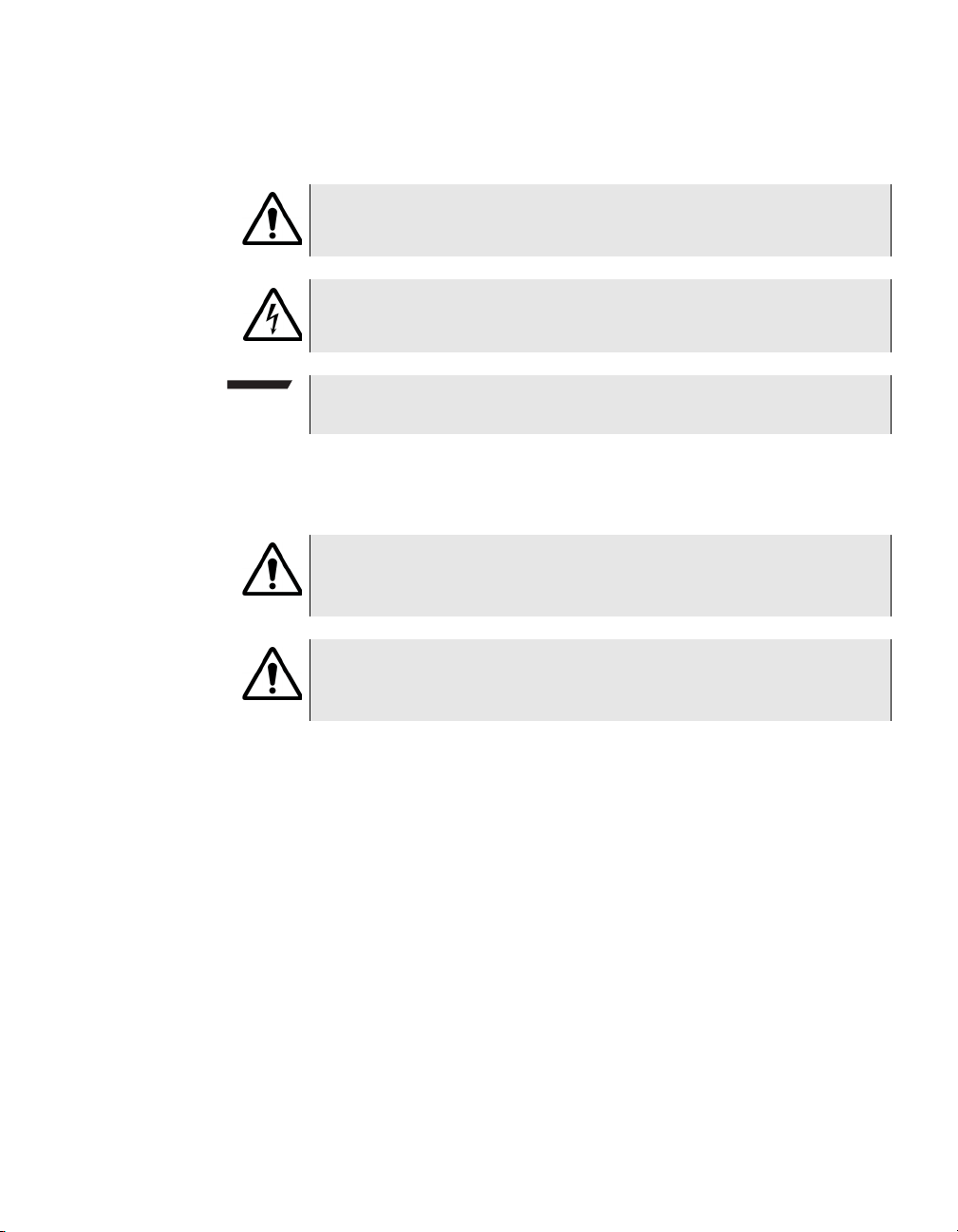
Table 4 Symbol conventions
This symbol represents a general hazard.
This symbol represents a risk of electrical shock.
NOTE:
This symbol represents a Note indicating related information or tip.
Table 5 Safety definitions
WARNING:
Indicates a potentially hazardous situation which, if not avoided,
could result in death or serious injury.
CAUTION:
Indicates a potentially hazardous situation which, if not avoided,
may result in minor or moderate injury.
FST-2802 TestPad User’s Guide Revision A
xxv
Page 26

About This Guide
Conventions
xxvi FST-2802 TestPad User’s Guide Revision A
Page 27

Chapter1
FST-2802 TestPad Overview
1
This chapter provides a general description of the FST-2802 TestPad.
Topics discussed in this chapter are as follows:
– “About the FST-2802 TestPad” on page 2
– “What’s new” on page 2
– “Features and capabilities” on page 3
– “Configurations and options” on page 6
– “Accessories” on page 8
– “Exploring the FST-2802” on page 15
– “Powering the TestPad” on page 20
– “Navigating the user interface” on page 21
FST-2802 TestPad User’s Guide Revision A 1
Page 28

Chapter 1 FST-2802 TestPad Overview
About the FST-2802 TestPad
About the FST-2802 TestPad
The FST-2802 TestPad Gigabit Ethernet Services Module is the ideal
telecommunications solution for testing and verifying Ethernet and
Fibre Channel network elements and services. The FST-2802 is optimized for field use because it is portable and easy-to-use. As a
member of the Acterna TestPad 2000 family of products, the FST-2802
has an easy-to-use touch screen user interface that simplifies test
setup and reduces test configuration time. The “smart tester” icondriven interface is easy to learn, and the large display provides ample
space for viewing test results.
The following items ship with the FST-2802:
– FST-2802 application module—The application module connects
to the UIM, allowing you to test 1G Ethernet links. Options are
available which enable you to test 10BaseT/100BaseT Ethernet,
1G Fibre Channel, and 2G Fibre Channel links. You can also
purchase the optional dual port configuration to generate and
analyze Ethernet or Fibre Channel traffic from two ports simultaneously.
– Y cable—The Y cable connects to the USB/Serial port, enabling
you to connect USB and serial devices to the FST-2802.
– User documentation—The FST-2802 ships with a User’s Guide
and a comprehensive help system.
Before testing, the FST-2802 must be connected to a FST-2000 user
interface module (UIM), which can be ordered separately (part number
2000-V6). The UIM ships with a VGA display, a battery, and an AC
adapter, which you use to supply power to the TestPad.
What’s new
The FST-2802 is a significant enhancement over previous TestPads.
The primary changes are as follows:
– BER testing—You can now use the FST-2802 to verify circuit
performance by sending BER patterns over switched (layer 2) and
unswitched (layer 1) networks.
2 FST-2802 TestPad User’s Guide Revision A
Page 29

Chapter 1 FST-2802 TestPad Overview
Features and capabilities
– 1G and 2G Fibre Channel testing—1G and 2G Fibre Channel
options are now available for the FST-2802 which enable you to
test and verify Fibre Channel network elements and services by
testing connectivity, measuring service disruption time and round
trip delay, and transmitting patterns to stress the jitter and noise
characteristics of Fibre Channel network elements and systems.
– Dual port configuration—An optional dual port configuration is now
available which allows you to generate and analyze Ethernet or
Fibre Channel traffic from two ports simultaneously.
– THRU mode for 10/100 Ethernet testing—If you purchase the
optional dual port configuration and the 10/100 option, you can
now monitor 10/100 traffic in THRU mode.
– Optional single-mode and multi-mode GigE and Fibre Channel
GBICs—You can now test Fibre Channel (and GigE Ethernet) on
an optical link using a single-mode or multi-mode GigE and Fibre
Channel GBIC.
– Optional copper GigE GBIC—You can now test 1G Ethernet on a
copper link using a copper GBIC.
– Optional single-mode long-haul GBIC—You can now test 1G
Ethernet over very long distances using a long-haul GBIC.
Features and capabilities
The FST-2802 provides you with the tools you need to provision
Ethernet or Fibre Channel service, verify end-to-end connectivity, and
analyze link performance by simulating different traffic conditions.
Features and capabilities of the FST-2802 include the following:
– Traffic generation—Using the FST-2802, you can generate frames
and configure traffic parameters such as bandwidth utilization,
frame length, and frame rate. You can simulate different network
traffic conditions and analyze the performance of a link by configuring traffic loads for constant, bursty, and ramped traffic.
– Filtered traffic—Using the FST-2802, you can filter received traffic
by defining a profile which specifies the frame characteristics of
the traffic you want to monitor.
FST-2802 TestPad User’s Guide Revision A
3
Page 30

Chapter 1 FST-2802 TestPad Overview
Features and capabilities
– Link status—Using the easy-to-interpret LEDs on the FST-2802,
you can obtain a quick summary of the state of the link you are
analyzing. The LEDs indicate the status of the link or a specific
traffic stream, allowing you to quickly verify circuit integrity or identify the source of a problem.
– Verify end-to-end connectivity—Using the FST-2802, you can
ensure physical layer integrity and verify end-to-end connectivity
of a circuit.
– Link utilization and throughput verification—Using the FST-2802,
you can generate traffic at a specific bandwidth to verify the error
free throughput of a link. The FST-2802 allows you to loopback
frames at the far end to qualify the link in both directions.
– Identify problems with faulty interfaces—Using the FST-2802, you
can perform basic troubleshooting of links and verify the capability
of network elements to support reliable communications by transmitting standard frames over a circuit.
– Round trip delay measurement—Using the FST-2802, you can
verify that a link complies with round trip delay requirements as
specified in a customer’s service level agreement. You can also
ensure frame loss and frame error statistics fall within the range
specified as acceptable.
– Service disruption time measurement—Using the FST-2802, you
can measure the amount of time it takes to switch service to a
protect line.
– Pattern transmission—Using the FST-2802, you can stress the
jitter and noise characteristics of Gigabit Ethernet and Fibre
Channel components and systems on physical layer networks by
transmitting continuous random test patterns (CRPAT), continuous
jitter test patterns (CJPAT), and the compliant supply noise pattern
(CSPAT).
Ethernet features
In addition to the standard features, the following features are available when performing Ethernet tests using the FST-2802:
– Auto-negotiation—You can configure auto-negotiation before
establishing the link, which ensures compatibility between the
FST-2802 and any installed Ethernet interface.
4 FST-2802 TestPad User’s Guide Revision A
Page 31

Chapter 1 FST-2802 TestPad Overview
Features and capabilities
– Frame verification—You can verify that the size and format of
Ethernet frames conforms to IEEE 802.3 or DIX (Digital/Intel/
Xerox) requirements, ensuring the capability of network elements
to support reliable communications.
– Jumbo frames—You can optionally transmit jumbo frames which
exceed the IEEE 802.3 maximum length of 1518 bytes.
– Loopback frame generation—You can generate loopback frames
to loop up a second FST-2802 at the far end. This feature allows
you to leave one FST-2802 at a central location to measure bidirectional throughput.
– IP Ping testing—You can send ping requests and respond to ping
messages from another Ethernet device to verify connectivity.
– RFC 2544 script—You can run a script which automates the test
procedures recommended in RFC 2544. The script prompts you to
select key parameters for each of the tests, runs the tests, and
then automatically generates a text file of results for the tests.
– User-assigned source MAC address—You can optionally change
the default MAC address assigned to each port of the FST-2802
when you configure tests.
Fibre Channel
features
FST-2000 TestPad
features
In addition to the standard features, the following features are available when performing Fibre Channel tests using the FST-2802:
– Frame verification—You can verify that the size and format of
Fibre Channel frames conforms to ANSI X3T11 requirements,
ensuring the capability of network elements to support reliable
communications.
– Loopback testing—You can generate loopback frames to loop up
a second FST-2802 at the far end. This feature allows you to leave
one FST-2802 at a central location to measure bi-directional
throughput.
The FST-2802 uses the Acterna FST-2000 TestPad Version 6 User
Interface Module (UIM), which runs under the Windows XP operating
system. The FST-2000 provides a variety of connectivity tools which
make installation and troubleshooting more efficient. Options and
accessories are also available which allow you to establish network
FST-2802 TestPad User’s Guide Revision A
5
Page 32

Chapter 1 FST-2802 TestPad Overview
Configurations and options
connections to the TestPad, use the TestPad to access a local Web
browser, or emulate a VT-100 terminal. Standard features of the FST2000 include:
– Print capability—You can print test configurations and test results
using the FST-2802. You can generate a print file at timed intervals or whenever a test ends. You can also manually print test
configurations, test results, and histograms at any time, and you
can encrypt print file data to ensure the integrity of the data transmitted to your supervisor or Technical Support department.
– Email test configurations and test results—If you purchase the
Networking option, you can email test configurations and test
results to your supervisor directly from the FST-2802.
– View Portable Document Format (PDF) files—You can launch and
view PDFs on the FST-2802.
– Command line remote control—You can configure the FST-2802
and perform tests from a remote PC or laptop by issuing remote
control commands.
– Remote GUI—If you purchase the Networking option, you can use
the Remote GUI to run the TestPad GUI from any remote device
with a Web browser, such as a PC or laptop. When viewing the
GUI from a remote device, you can configure and perform tests,
view test results, and do anything you could do using the FST2802 itself.
– VNC Viewer—You can launch the Virtual Network Computing
(VNC) viewer to run remote applications from the FST-2802.
– FTP—If you purchase the Networking option, you can use FTP to
transfer files to and from the FST-2802.
– FST-2802 Help—You can display FST-2802 Help which includes
detailed instructions for configuring and performing tests, comprehensive result descriptions, and a glossary of terms.
Configurations and options
When you order a FST-2802, you order a single or dual port configuration which allows you to test 1G Ethernet. You can also expand your
testing capabilities by purchasing optional interfaces for the FST-2802,
including a 10/100 BaseT Ethernet interface, a 1G Fibre Channel interface, and a 2G Fibre Channel interface. Options are also available for
6 FST-2802 TestPad User’s Guide Revision A
Page 33

Chapter 1 FST-2802 TestPad Overview
Configurations and options
the FST-2000 which allow you to launch a Web browser, emulate a VT100 terminal, run the GUI from a remote device, or automate tests
using test scripts.
Ta bl e 1 lists the FST-2802 configurations.
Table 1 FST-2802 configurations
Configuration Part Number Allows you to test:
Single port 2802-GIGE 1G Ethernet using one GBIC port.
Dual port 2802-DUAL 1G Ethernet using two GBIC ports.
FST-2802 options
The FST-2802 offers the following application module options:
– 10/100 interface (part number 2802-FE)—Using this option, you
can test 10BaseT and 100BaseTX links. If you purchase the
optional dual-port configuration, you can transmit and analyze 10/
100 and/or 1G Ethernet traffic from both ports simultaneously.
– 1G Fibre Channel interface (part number 2802-1G-FC)—Using
this option, you can test 1G Fibre Channel network elements and
services. If you purchase the optional dual-port configuration and
2G Fibre Channel interface, you can transmit and analyze 1G and/
or 2G Fibre Channel traffic from both ports simultaneously.
– 2G Fibre Channel interface (part number 2802-2G-FC)—Using
this option, you can test 2G Fibre Channel network elements and
services. If you purchase the optional dual-port configuration and
1G Fibre Channel interface, you can transmit and analyze 1G and/
or 2G Fibre Channel traffic from both ports simultaneously.
– VLAN Tagging (part number 2802-VLAN)—Using this option, the
FST-2802 can transmit VLAN (virtual LAN) tagged frames,
enabling you to verify that an Ethernet link supports VLAN tagging.
The FST-2802 can also analyze received traffic to verify that the
required bandwidth is allocated to tagged frames on a link and
determine that VLAN prioritization is functioning properly.
– Layer 2 IP Address Filter (part number 2802-IP FILTER)—Using
this option, you can monitor Ethernet traffic for IP addresses, and
view filtered layer 2 link statistics for a selected IP address.
FST-2802 TestPad User’s Guide Revision A
7
Page 34

Chapter 1 FST-2802 TestPad Overview
Accessories
FST-2000 TestPad
options
Accessories
The features provided by FST-2000 TestPad options are available for
any application module you attach to the TestPad.
The FST-2000 TestPad offers the following options:
– Web browser (part number 2000-WEB)—Using this option, you
can launch a Web browser on the FST-2802 to access information
on the Internet or your company’s intranet.
– VT100 emulation (part number 2000-VT100)—Using this option,
the FST-2802 can emulate a VT100 terminal. This option includes
a DB-9 Female to DB-9 Male cable, enabling you to establish a
serial connection for VT100 emulation.
– Scripting (part number 2000-SCR)—Using this option, you can
write your own test scripts using the Tcl/Tk scripting language to
automate and standardize your testing processes.
– Networking (part number 2000-NET)—Using this option, you can
establish network connections to the FST-2802 for a variety of
applications.
You can also purchase accessories for the FST-2802 such as GBICS
for testing GigE Ethernet and Fibre Channel links, card and cables for
establishing remote connections, and printers. To order accessories
for the FST-2802, contact Acterna Customer Care.
8 FST-2802 TestPad User’s Guide Revision A
Page 35

Chapter 1 FST-2802 TestPad Overview
Accessories
GBIC accessories
Ta bl e 2 lists the GBICs available for testing GigE Ethernet and Fibre
Channel links. Please consult your GBIC manufacturer’s data sheet
for detailed specifications.
Table 2 GBIC accessories
Accessory Part Number Used to…
Multi-mode GigE GBIC AC-GBIC-SX Test 1G Ethernet on optical links over
distances up to:
– 275 meters with 62.5µm multi-
mode fiber
– 550 meters with 50µm multi-
mode fiber
NOTE: This GBIC is not recommended for use with 10µm singlemode fiber.
Single-mode GigE GBIC AC-GBIC-LX Test 1G Ethernet on optical links over
distances up to:
– 275 meters with 62.5µm multi-
mode fiber
– 550 meters with 50µm multi-
mode fiber
– 10,000 meters with 10µm single-
mode fiber
NOTE: This GBIC is not recommended for use with multi-mode
fiber.
FST-2802 TestPad User’s Guide Revision A
9
Page 36

Chapter 1 FST-2802 TestPad Overview
Accessories
Table 2 GBIC accessories
Accessory Part Number Used to…
Multi-mode GigE and Fibre
Channel GBIC
AC-GBIC-ALLRATE-SX Test 1G Ethernet, 1G Fibre Channel,
and 2G Fibre Channel on optical
links over distances up to:
1G Ethernet
– 275 meters with 62.5µm multi-
mode fiber
– 550 meters with 50µm multi-
mode fiber
1G Fibre Channel
– 300 meters with 62.5µm multi-
mode fiber
– 550 meters with 50µm multi-
mode fiber
2G Fibre Channel
– 150 meters with 62.5µm multi-
mode fiber
– 300 meters with 50µm multi-
mode fiber
NOTE: This GBIC is not recommended for use with 10µm singlemode fiber.
10 FST-2802 TestPad User’s Guide Revision A
Page 37

Chapter 1 FST-2802 TestPad Overview
Table 2 GBIC accessories
Accessory Part Number Used to…
Accessories
Single-mode GigE and Fibre
Channel GBIC
AC-GBIC-ALLRATE-LX Test 1G Ethernet, 1G Fibre Channel,
and 2G Fibre Channel over distances
up to:
1G Ethernet
– 275 meters with 62.5µm multi-
mode fiber
– 550 meters with 50µm multi-
mode fiber
1G Fibre Channel
– 300 meters with 62.5µm multi-
mode fiber
– 550 meters with 50µm multi-
mode fiber
2G Fibre Channel
– 225 meters with 62.5µm multi-
mode fiber
– 225 meters with 50µm multi-
mode fiber
– 10,000 meters with 10µm single-
mode fiber
Copper GigE GBIC AC-GBIC-COPPER Test 1G Ethernet on copper links
over distances up to 100 meters.
NOTE: This copper GBIC (AC-GBIC-
COPPER) does not support autonegotiation; therefore, the FST2802’s link partner must also use a
copper GBIC that does not support
auto-negotiation.
Single-mode Long-haul GigE
GBIC
FST-2802 TestPad User’s Guide Revision A
AC-GBIC-LONGHAUL Test 1G Ethernet over distances up
to 80 kilometers on optical links.
NOTE: This GBIC is not recom-
mended for use with multi-mode
fiber.
11
Page 38

Chapter 1 FST-2802 TestPad Overview
Accessories
NOTE:
The optional SX, LX, and copper GBICs offered by Acterna as
accessories comply with the Revision 5.5 GBIC specification. The
long-haul GBIC complies with the Revision 5.4 GBIC specification.
Please refer to your GBIC manufacturer’s site for detailed specifications.
Connectivity
accessories
Ta bl e 3 lists the accessories available for establishing remote connec-
tions.
Table 3 Connectivity accessories
Accessory Part Number Used to…
DB-9 Female to
DB-9 Female null
modem cable
Serial PCMCIA
card
Analog dial-up
modem PCMCIA
card
CB-014491 Connect a laptop to the
serial connector of the Y
cable. Typically used for
remote control command
operation.
2000-SERIAL Provide a second serial
connection to the TestPad.
This allows you to connect
two serial devices to the
TestPad—one to the serial
connector of the Y cable,
and one to the connector
provided on the serial
PCMCIA card.
2000-ANLGMODEM
Establish an analog dial-up
connection to the TestPad.
Ships with an RJ-11 phone
cable.
RJ-11 phone cable
(replacement)
CB-834011 Connect an Analog Dial-Up
12 FST-2802 TestPad User’s Guide Revision A
Modem PCMCIA card to a
phone jack.
Page 39

Chapter 1 FST-2802 TestPad Overview
Table 3 Connectivity accessories (Continued)
Accessory Part Number Used to…
Accessories
Ethernet 10/100
Base-T LAN PCMCIA card
Ethernet Type III
LAN PCMCIA card
2000-LAN Establish an Ethernet con-
nection from the TestPad to
a laptop or LAN.
– Ships with an Ethernet
LAN cable for LAN connections (replacement
cables can be ordered
if necessary).
– Laptop connections
require an Ethernet
cross-over cable (part
number CB-834251).
2000-LAN-TYPE3 Establish an Ethernet con-
nection from the TestPad to
a laptop or LAN.
– Ships with a 6 ft. Ether-
net LAN extension
cable for LAN connections (replacement
cables can be ordered
if necessary).
– Laptop connections
require an Ethernet
cross-over cable (Part
number: CB-834251).
Ethernet LAN cable
CB-016267 Connect an Ethernet PCM-
(replacement)
802.11b Wireless
2000-WLAN Establish an 802.11 wire-
LAN PCMCIA card
Bluetooth Wireless
2000-BT-MODEM Establish a Bluetooth wire-
PCMCIA card
USB Direct Con-
CB-18944 Establish a direct USB con-
nect cable
FST-2802 TestPad User’s Guide Revision A
CIA card in the TestPad to
an Ethernet jack.
less connection to the TestPad.
less connection to the TestPad.
nection from the TestPad to
a laptop via the USB connector on the Y cable.
13
Page 40

Chapter 1 FST-2802 TestPad Overview
Accessories
Table 3 Connectivity accessories (Continued)
Accessory Part Number Used to…
Print accessories
Ethernet cross-over
cable (6 ft.)
Y cable (replacement)
CB-834251 Connect a PCMCIA Ether-
net card in the TestPad to a
laptop.
CB-45570 Connect to the USB/Serial
port, enabling you to connect serial and USB
devices to the TestPad.
Ta bl e 4 lists the available print accessories.
Table 4 Print accessories
Accessory Part Number Used to…
Serial Printer PR-40B Print test configurations,
test results, and histograms
from the TestPad.
– Requires DB-9 Female
to DB-9 Male cable
(part number: CB-
018179) to connect to
the TestPad.
DB-9 Female to DB-9
Male cable
DB-9 Female to DB25 Male Cable
CB-018179 Connect a PR-40B printer
CB-45766 Connect a PR-40A printer
14 FST-2802 TestPad User’s Guide Revision A
to the serial connector of
the Y cable.
to the serial connector of
the Y cable.
NOTE: The PR-40A printer
is no longer available for
purchase.
Page 41

Chapter 1 FST-2802 TestPad Overview
Table 4 Print accessories (Continued)
Accessory Part Number Used to…
Exploring the FST-2802
Additional
accessories
USB Printer 2000-USB-
PRINTER
Print test configurations,
test results, and histograms
from the TestPad. The USB
Printer connects to the
USB connector on the Y
cable via a cable (supplied
with the printer).
Ta bl e 5 lists additional accessories available for the FST-2802.
Table 5 Additional accessories
Accessory Part Number Connects to…
USB Portable
Keyboard
USB Mouse 2000-USB-MOUSE The USB connector of the
USB Hub 2000-USB-HUB The USB connector of the
2000-USB-KEYBRD The USB connector of the
Y cable.
Y cable.
Y cable. Connecting a USB
hub enables you to connect
multiple USB devices to the
TestPad simultaneously.
2.5mm Headset 2000-HEADSET The Headset jack on the
ATA PCMCIA
Storage Card
Exploring the FST-2802
The following sections introduce you to the top, bottom, front, and LED
display panels of the FST-2802.
FST-2802 TestPad User’s Guide Revision A
bottom panel of the TestPad.
2000-STORAGE The top or bottom PCMCIA
card slot on the TestPad.
15
Page 42
Chapter 1 FST-2802 TestPad Overview
Exploring the FST-2802
Top panel
USB/Serial port
USB/Serial
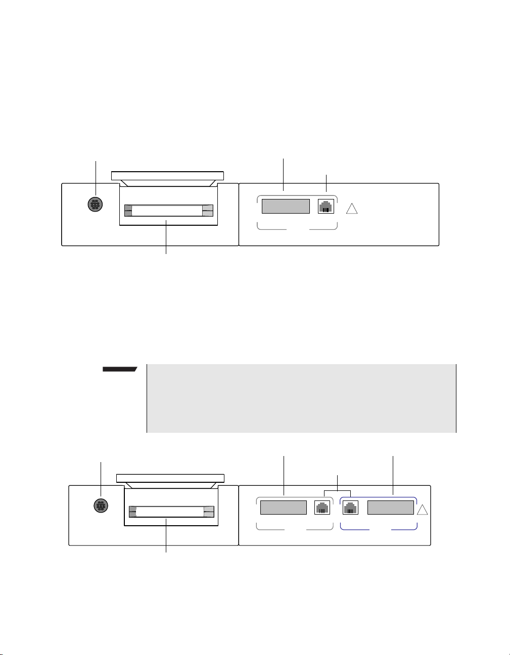
The top panel provides the USB/Serial port, dual PCMCIA card slot,
RJ-45 connector(s) for 10/100 Ethernet testing, and GBIC port(s) for
1G Ethernet, 1G Fibre Channel, and 2G Fibre Channel testing.
Figure 1 illustrates the single port configuration with one RJ-45
connector and one GBIC port (outlined in grey).
GBIC port
RJ-45 connector
TX RX
1 Gbps / 2Gbps
PORT 1
10/100 Mbps
!
PCMCIA card slots
Figure 1 FST-2802 top panel (single port configuration)
If you purchase the dual port configuration (see Figure 2), a second
RJ-45 connector and GBIC port is available. The Port 1 GBIC port and
RJ-45 connector are outlined on the unit in grey; the Port 2 GBIC port
and RJ-45 connector are outlined on the unit in blue.
NOTE:
You can easily determine which port is currently selected by looking
at the buttons on the main screen. When Port 1 is selected, the
buttons on the main screen are grey. When Port 2 is selected, the
buttons are blue.
USB/Serial port
USB/Serial
PCMCIA card slots
GBIC port GBIC port
RJ-45 connectors
TX RX
1 Gbps / 2Gbps
PORT 1
Figure 2 FST-2802 top panel (dual port configuration)
16 FST-2802 TestPad User’s Guide Revision A
10/100 Mbps
TX RX
1 Gbps / 2Gbps
PORT 2
!
Page 43
Chapter 1 FST-2802 TestPad Overview
Exploring the FST-2802
USB/Serial port
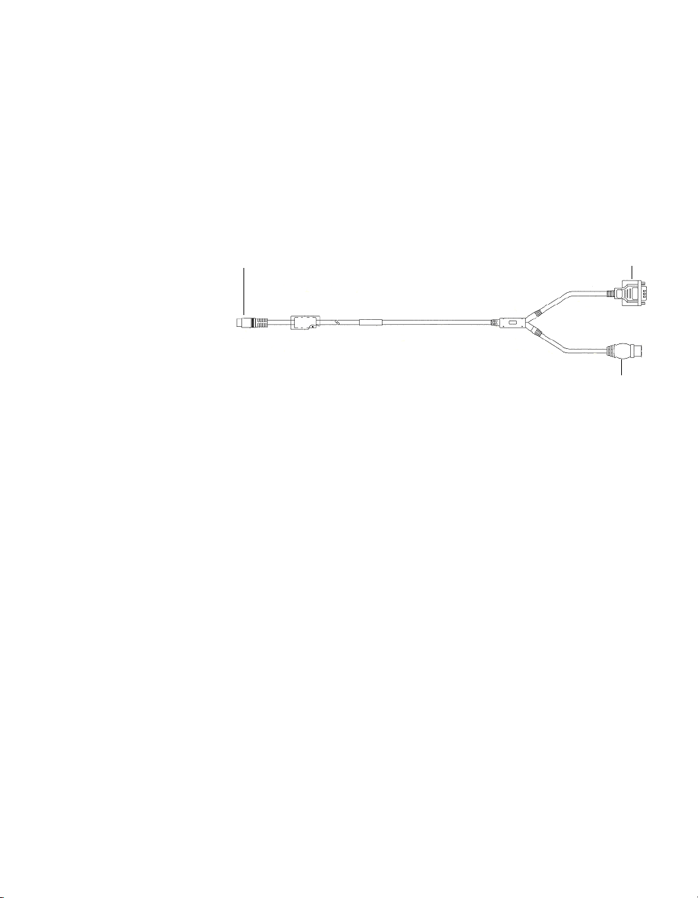
The USB/Serial port provides a 10-pin connector for the Y cable. By
attaching the Y cable shipped with the FST-2802 (see Figure 3), you
can connect serial devices such as a printer, laptop, or PC, and USB
devices, such as a keyboard, mouse, printer, or hub to the TestPad.
The serial connector of the Y cable is configured as a Data Terminal
Equipment (DTE) connector; the USB port is configured as a USB
host.
USB/Serial port connector
Serial connector
USB connector
Figure 3 Y cable
To connect serial and USB devices to the TestPad, first connect the Y
cable to the TestPad. If you are connecting USB devices such as a
mouse, keyboard, hub, or printer, you connect the device directly to
the USB connector of the Y cable. If you are connecting a serial
device, you connect an intermediate cable to the Y cable, and then
connect the other end of the cable to the device.
PCMCIA card slots
For descriptions of each of the intermediate cables, see Tab l e 3 o n
page 12 and Table 4 on page 14.
Two PCMCIA card slots are provided on the TestPad. PCMCIA cards
are available for the TestPad which allow you to establish modem,
wireless, Ethernet, or serial connections to the TestPad and store test
configurations, test results, and print files.
Ethernet LAN, Ethernet cross-over, and some serial cables are also
attached to associated PCMCIA cards which are inserted in the TestPad.
For descriptions of each of the connectivity cards offered as an accessory by Acterna, see Table 3 on page 12.
FST-2802 TestPad User’s Guide Revision A
17
Page 44
Chapter 1 FST-2802 TestPad Overview
Exploring the FST-2802
Bottom panel
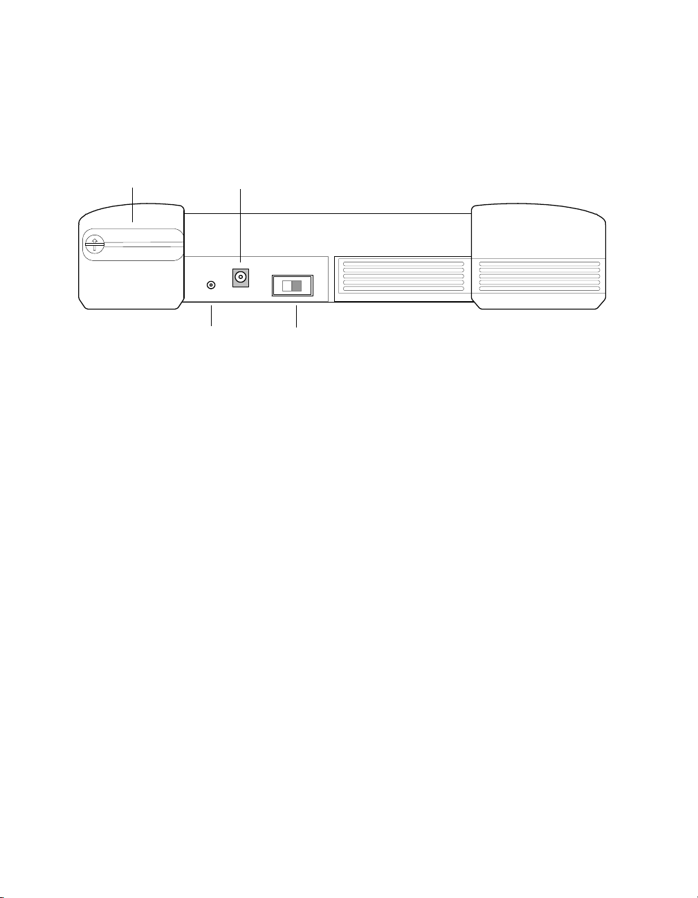
Battery access panel
Headset jack
The bottom panel provides the battery access panel, headset jack, DC
IN jack (used with the AC adapter to power the TestPad), and the
power switch. See Figure 4.
DC IN jack
HEADSET DC IN
01
Power switch
Figure 4 FST-2802 bottom panel
18 FST-2802 TestPad User’s Guide Revision A
Page 45
Chapter 1 FST-2802 TestPad Overview
Exploring the FST-2802
Front panel
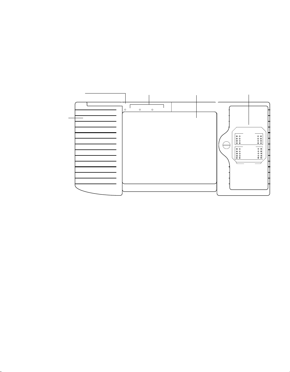
Microphone
Speaker
The front panel provides a touch-sensitive LCD screen that displays
the user interface. The user interface allows you to set up the TestPad,
configure tests, and display test results (see “Navigating the user inter-
face” on page 21). The power LEDs, status LEDs, speaker, and micro-
phone are also located on the front panel. See Figure 5.
Power LEDs
CHARGEPOWER LOW BATTERY
User interface
LED Panel
Port 1
10/100 Mbps
SYNC
LINK ACTIVE
FRAME
SUMMARY
1 Gbps/2 Gbps
SIGNAL
SYNC
LINK ACTIVE
FRAME
SUMMARY
History
Port 2
Figure 5 FST-2802 front panel
FST-2802 TestPad User’s Guide Revision A
19
Page 46
Chapter 1 FST-2802 TestPad Overview
Powering the TestPad
LED display panel
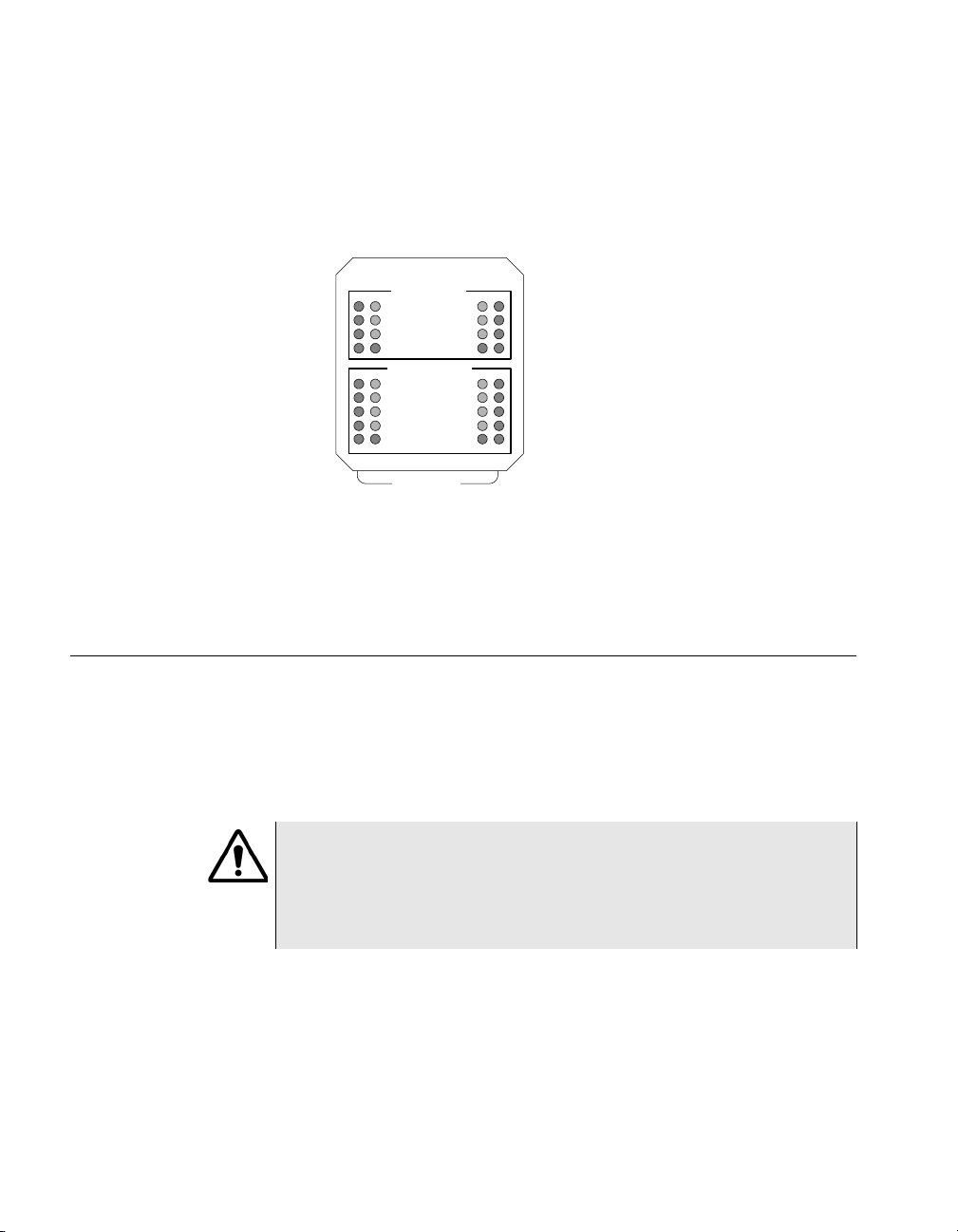
The LED display panel provides current and historical Status and
Alarm LEDs for each port. The inside column of LEDs indicates the
current condition or state of the link; the outside column of LEDs indicates the historical condition of the link. See Figure 6.
Figure 6 LED display panel
For a detailed description of each LED, see Chapter 7 “Test Results”.
Powering the TestPad
Port 1
10/100 Mbps
SYNC
LINK ACTIVE
FRAME
SUMMARY
1 Gbps/2 Gbps
SIGNAL
SYNC
LINK ACTIVE
FRAME
SUMMARY
History
Port 2
Power is supplied to the FST-2802 by the battery or the AC power
adapter. To supply power using the adapter, plug the adapter into the
DC IN jack located on the bottom panel of the FST-2802. For power
specifications see “Electrical specifications” on page 247.
WARNING:
RISK OF DAMAGE TO UNIT. Do not use the adapter supplied with
the Acterna FST-2000 User Interface Module (UIM) with older UIMs
labeled TTC 2000 or TestPad 2000. Do not use the adapter supplied with older UIMs with the Acterna FST-2000 UIM.
To power the TestPad
– Turn the power switch to the ON position.
The Power LED, located on the front panel, illuminates green when the
TestPad is powered.
20 FST-2802 TestPad User’s Guide Revision A
Page 47
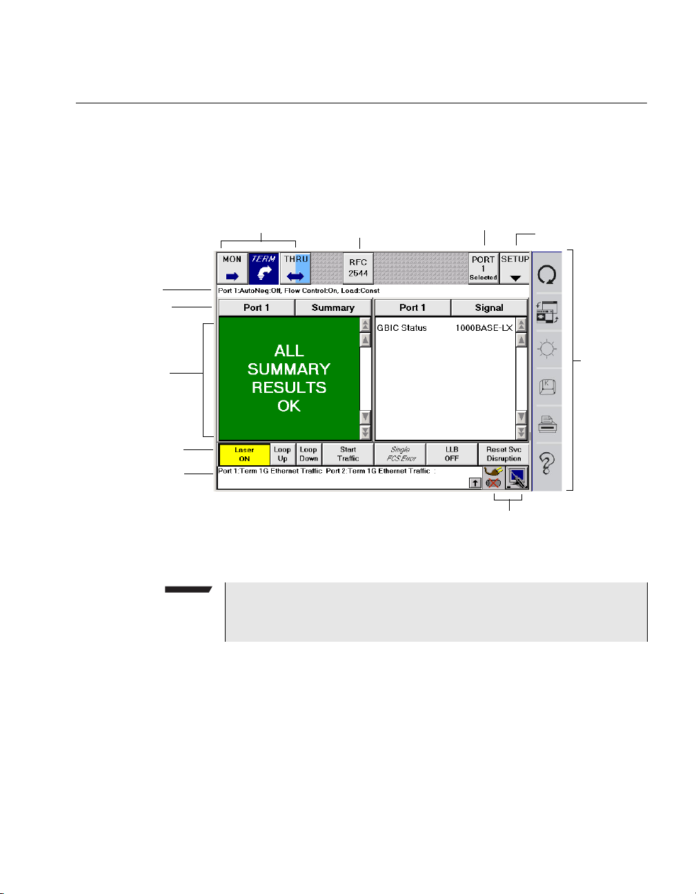
Navigating the user interface
The user interface lets you set up the TestPad, configure tests, and
display test results. The touch-sensitive screen is divided into separate
areas for TestPad set up, test configuration, and test results.
Chapter 1 FST-2802 TestPad Overview
Navigating the user interface
Configuration
summary bar
Result buttons
Result display
Action buttons
Message
display
Application buttons
RFC 2544
PORT Swap
System buttons
SETUP
Figure 7 FST-2802 dual port user interface
NOTE:
We recommend using the stylus supplied with the TestPad to activate functions on the touch-sensitive screen.
Extended
keypad
Application
buttons
The application buttons, located on the upper-left corner of the interface, provide quick access to each test for the currently selected port.
The buttons are organized by operating mode (MON, TERM, and for
dual port units, THRU), rate and protocol (for example, 1G Ethernet),
and then test.
FST-2802 TestPad User’s Guide Revision A
21
Page 48
Chapter 1 FST-2802 TestPad Overview
Navigating the user interface
RFC 2544 button
Port Swap button
SETUP button
The RFC 2544 button runs a script which automates the Ethernet test
procedures recommended in RFC 2544. The script prompts you for
key parameters, runs the tests, and then automatically generates a
text file of results for the tests.
If you have a dual port FST-2802, the Port Swap button toggles
between Port 1 (grey) and Port 2 (blue), and allows you to select a port
before choosing a test application, configuring a test, or performing an
action (such as turning the laser on).
The default port is Port 1. When Port 1 is selected, the buttons on the
main screen are grey, and “Port 1 Selected” appears on the button.
When Port 2 is selected, the buttons are blue, and “Port 2 Selected”
appears on the button. The THRU button for dual port units is always
blue and grey, since thru mode applies to both ports.
The Port Swap button does not appear on the single port user interface.
The SETUP button provides access to the tabs used to configure your
tests. After you select the port and application for a test, you select the
Setup button to configure the test. For details on configuring a test, see
“Step 1: Configuring a test” on page 94.
Configuration
summary bar
22 FST-2802 TestPad User’s Guide Revision A
The configuration summary bar displays the application selected for
each port. For example, if you select and configure a 1G Ethernet
traffic generation test on Port 1, and a 1G Ethernet pattern test application on Port 2, the following information appears in the configuration
summary bar:
PORT 1:Term 1G Ethernet Traffic Port 2:Term 1G
Ethernet Pattern Test
Page 49

Chapter 1 FST-2802 TestPad Overview
Navigating the user interface
Result buttons
Result display
Action buttons
Message display
In each result pane there is a Result Group and Result Category
button. The Result Group button allows you to set the port for the
results; the Result Category button allows you to set the results category. By selecting a different port or category for each pane, you can
view two sets of results at the same time.
The test results for the TestPad appear in the result display.
The action buttons are located above the message display. The action
buttons perform additional functions specific to the application you
specified for the currently selected port. A different set of action
buttons appears each time you select a mode of operation. For
example, if you configure a port for a 1G Ethernet, 1G Fibre Channel,
or 2G Fibre Channel test, the Laser On/Off action button appears,
enabling you to turn the laser on and off. The buttons may or may not
be active depending on the application you select.
The message display shows the operating mode, protocol, rate,
status, and current events for each active port. For example, the
message display might display a confirmation message informing you
that a TestPad on the far end of a circuit is in loopback mode.
System buttons
– To view historical messages, select the up arrow in the message
display. The Message History Pane appears, listing up to ten
historical messages.
– To close the pane and return to the main screen, select the down
arrow.
Two system buttons are located to the right of the message display.
FST-2802 TestPad User’s Guide Revision A
23
Page 50

Chapter 1 FST-2802 TestPad Overview
Navigating the user interface
Tools button
Selecting the Tools button displays the Tools menu which lists the
commands in Ta bl e 6 .
Table 6 Tools menu commands
Command… Used to…
Programs Access a variety of applications, such as the
On-screen Keyboard, PDF Viewer, and VNC
Viewer. If you purchase the Web browser or
VT-100 emulation options, the associated
applications are also listed as menu commands.
TestPad Settings Specify screen saver, brightness, speaker, and
date and time settings.
Connectivity Specify parameters for printer, network, Serial
Remote Command Line, and Remote GUI connections.
File Management Access the File Management dialog box to
manage files and transfer files to and from the
TestPad using FTP.
FST-2802 Settings Access the FST-2802 revision information and
load upgrades and options. You can also reset
the FST-2802 by clearing NOVRAM and
returning the unit to factory default settings.
Print Management Set up and schedule print events, create head-
ings for print output, and print test configurations, test results, and histograms.
Store/Recall Setups Access the Saved Setups dialog box. Using the
options on the screen, you can store test configurations. After you store a configuration, you
can recall and load the configuration to automatically configure a test.
AutoMATE If you purchase the scripting option, access the
automated test scripts you develop using Tcl/
Tk.
Help Launch FST-2802 Help.
Restart Port 1 Restart the test on Port 1.
Restart Port 2 Restart the test on Port 2.
24 FST-2802 TestPad User’s Guide Revision A
Page 51
Chapter 1 FST-2802 TestPad Overview
Navigating the user interface
Table 6 Tools menu commands (Continued)
Command… Used to…
Restart Both Ports Restart tests on Port 1 and Port 2.
NOTE: You can also restart tests on both ports
using the Test Restart button on the Extended
Keypad.
Power Status button
Extended Keypad
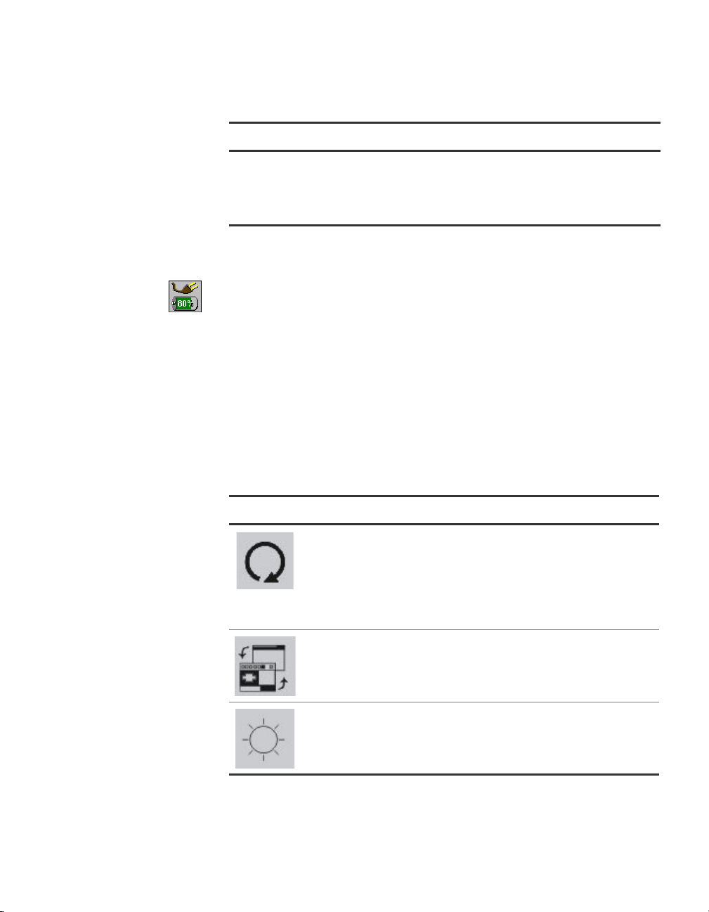
The Power Status button displays current battery strength by bar
graph and percentage and indicates whether the TestPad is powered
using an AC power adapter.
The Extended Keypad is located to the right of the touch-sensitive
screen. The keys are used to initiate specific operations on the
TestPad (such as a test restart or screen toggle), launch the on-screen
keyboard or online help, or access dialog boxes to control the brightness of the screen and to set up print events. Table 7 describes the
function of each key.
Table 7 Extended Keypad keys
Icon Description
Restart—Press this key to restart the tests on each active
port simultaneously. When you restart a test, the TestPad
resets the current test result totals and clears any errors
and/or alarms.
NOTE: If you want to restart a test on a specific port, select
Tools > Restart Port 1 or Tools > Restart Port 2.
Toggle Screen—Press this key to toggle between applications. For example, if you launched the Web browser, press
this key to toggle between the TestPad user interface and
the browser.
Brightness—Press this key to access the Screen Brightness
tab.
FST-2802 TestPad User’s Guide Revision A
25
Page 52
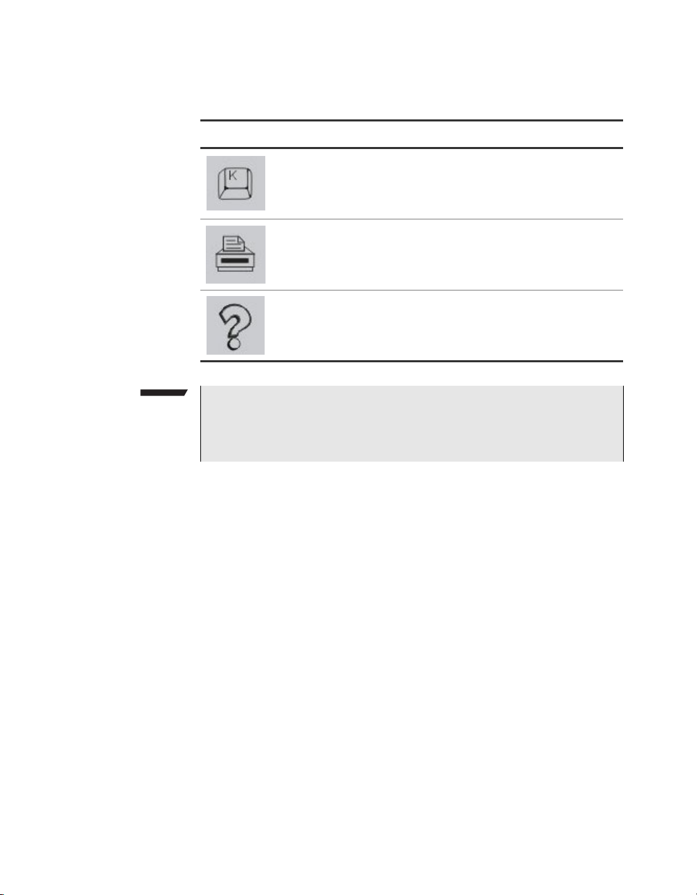
Chapter 1 FST-2802 TestPad Overview
Navigating the user interface
Table 7 Extended Keypad keys (Continued)
Icon Description
NOTE:
When you use the Remote GUI, you can use the Tools menu to
access each of the commands associated with the Extended Keypad keys.
Keyboard—Press this key to launch the on-screen keyboard.
Printer Setup—Displays a series of tabs which allow you to
schedule or generate print output on the TestPad.
Help—Launches FST-2802 Help.
26 FST-2802 TestPad User’s Guide Revision A
Page 53

Chapter2
Basic Operations
2
This chapter provides step-by-step instructions for each of the basic
operations you can perform using the FST-2802. Topics discussed in
this chapter are as follows:
– “Connecting and swapping application modules” on page 28
– “Maintaining the battery” on page 30
– “Connecting a USB device” on page 33
– “Setting up the FST-2802” on page 34
– “Defining the Custom result category” on page 45
– “Restoring factory defaults” on page 46
– “Printing test configurations, test results, and histograms” on
page 47
– “Using the on-screen keyboard” on page 61
– “Sending e-mail” on page 62
– “Launching Adobe Acrobat Reader” on page 66
– “Launching the VNC Viewer” on page 67
– “Launching the Web browser” on page 68
– “Emulating a VT100 terminal” on page 69
– “Using the Remote GUI” on page 69
– “Managing files” on page 71
FST-2802 TestPad User’s Guide Revision A 27
Page 54

Chapter 2 Basic Operations
Connecting and swapping application modules
Connecting and swapping application modules
Connecting an application module involves holding it at a slight angle
to the UIM, inserting the UIM into the application module slot, gently
rotating the application module into a parallel position with the UIM,
and then sliding the application module into the UIM.
Swapping application modules involves turning the TestPad off,
disconnecting the attached application module from the UIM, and then
attaching the new application module to the UIM.
NOTE:
FST-2802’s which are compatible with the Version 6 UIM are identified with a “Version 6 Compatible” label on the back of the application module.
FST-2802 application modules running software version 3.0 and
higher require a Version 6 or higher UIM. If you connect a FST-2802
application module running software version 3.0 or higher to an
older UIM, a message will appear on the user interface instructing
you to remove the application module and attach it to a newer UIM.
To connect or swap application modules
1 If an application module is connected to the UIM and the TestPad
is on, turn off the TestPad.
2 If you are swapping application modules, turn the screw on the
front of the application module counter-clockwise to release the
application module; otherwise, proceed to step 4.
3 Disconnect the application module from the UIM by slowly pulling
the two modules apart, and then gently rotating the right side of
the UIM into an upwards position.
4 On the back of the application module you are about to connect,
verify that the following labels appear (indicating that the application module is compatible with a Version 6 or higher UIM):
– If you are connecting a FST-2802, verify that a label appears
stating “Version 6 Compatible”.
– If you are connecting any other application module, verify that
a label appears stating “FST-2000 INTEROPERABLE”.
28 FST-2802 TestPad User’s Guide Revision A
Page 55
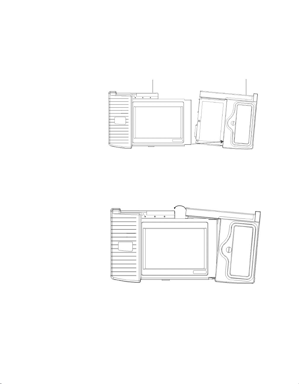
Chapter 2 Basic Operations
Connecting and swapping application modules
5 While holding the application module at a slight angle (see
Figure 8), insert the bottom right corner of the UIM no more than
1/4 inch into the inside bottom edge of the application module slot.
Application moduleUIM
Figure 8 UIM insertion into application module slot
6 Gently rotate the application module into a parallel position with
the UIM (see Figure 9 on page 29).
Rotate
Figure 9 Rotating the application module
FST-2802 TestPad User’s Guide Revision A
29
Page 56
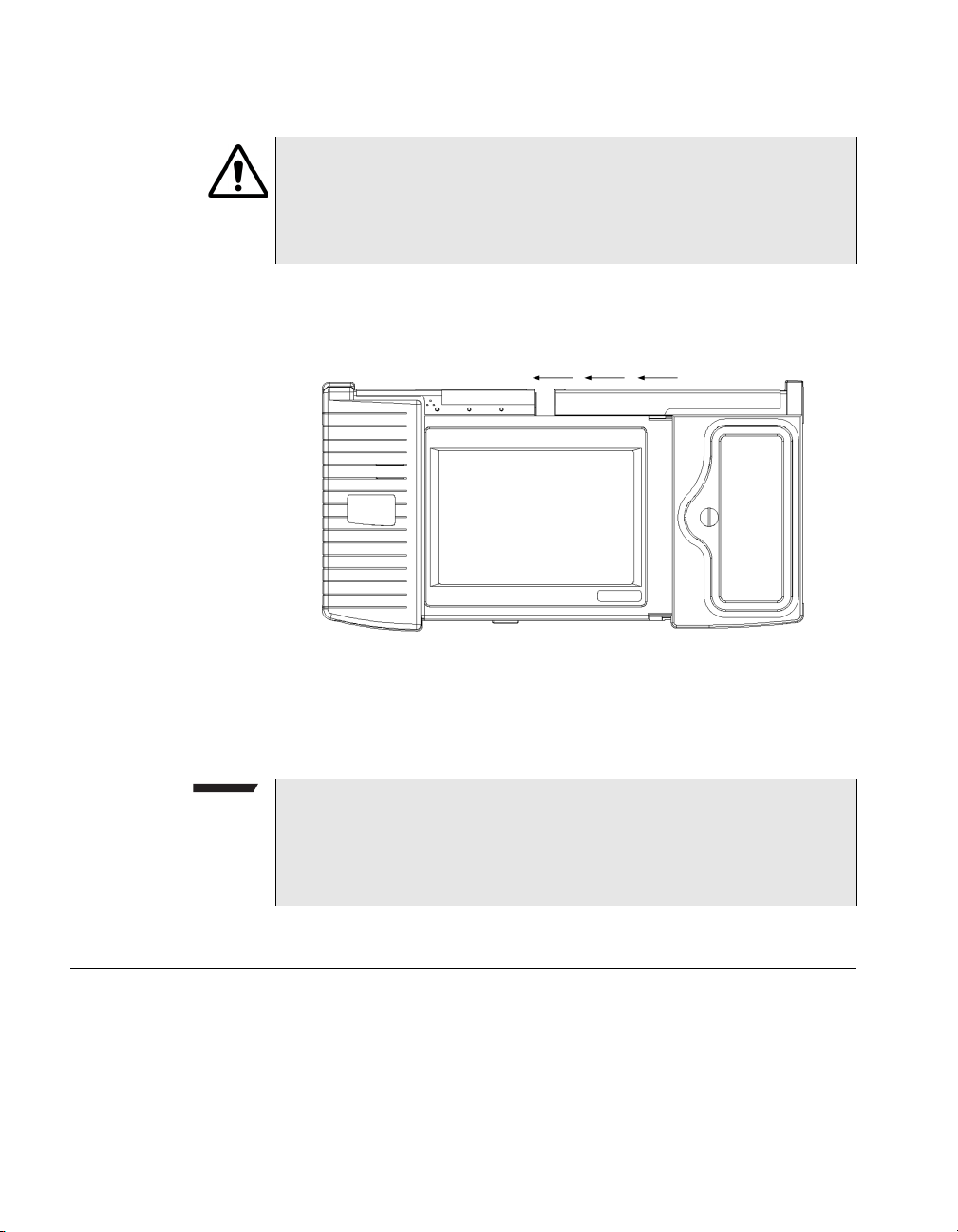
Chapter 2 Basic Operations
Maintaining the battery
CAUTION: DAMAGE TO TESTPAD
If you attempt to connect the UIM and application module at an
angle, you may damage the TestPad. Be certain to align the UIM
and application module in a parallel position before connecting the
modules.
7 Slide the application module into the UIM, keeping the two
modules parallel at all times (see Figure 10).
Figure 10 UIM and application module connection
8 Turn the screw clockwise to secure the TestPad.
The TestPad is ready for use.
NOTE:
When you turn the TestPad on for the first time, the UIM and the
application module require several minutes to initialize the software.
Do not turn the power off during initialization or you may corrupt the
files.
Maintaining the battery
The TestPad comes equipped with a rechargeable Nickel-Metal
Hydride (NiMH) battery. The battery life of a fully-charged battery
varies depending on the type of functions that you are performing.
30 FST-2802 TestPad User’s Guide Revision A
Page 57

Chapter 2 Basic Operations
Maintaining the battery
If the battery is not charged with sufficient capacity to power the
TestPad, the TestPad will not completely power up, and the LOW
BATTERY LED will illuminate. You can power the TestPad and
recharge the battery using the supplied AC adapter.
To prolong the life span of the battery, follow the guidelines below:
– Store the battery in a cool, dry, and clean environment. Do not
leave the battery in a car or truck, particularly during extremely
warm weather.
– Use the AC adapter to power up the TestPad the first time you use
the TestPad, or after prolonged storage.
– Before using the battery to power the TestPad, check the battery
capacity.
– If the battery capacity is depleted or if the battery has been stored
for a prolonged period, use the Acterna battery charger to charge
the battery. Do not use an un-approved charger.
– Condition the battery after prolonged storage or 30 cycles of use.
To condition the battery, deeply discharge the battery, and then
recharge the battery fully three times.
– If the TestPad will not be used for more than a week, remove the
battery.
– Do not charge the battery after exposure to extremely hot or cold
temperatures.
– If the battery capacity is depleted and you are not ready to
recharge the battery, turn the TestPad power OFF.
– Always carry a fully charged spare battery.
Viewing the
battery charge
status
To view the battery charge status
– Look at the Power Status button on the user interface. The button
displays the current battery strength using a bar graph and
percentage.
FST-2802 TestPad User’s Guide Revision A
31
Page 58
Chapter 2 Basic Operations
Maintaining the battery
Charging the
battery
The Low Battery LED illuminates when the battery is below 25 percent
capacity. You can recharge the battery using an AC adapter.
NOTE:
Environmental conditions such as the temperature of the battery
may cause the charging process to terminate before the battery is
completely recharged. The internal battery charger can operate
when the TestPad is on; however, to ensure a complete recharge,
turn the TestPad off, remove the AC adapter, and then verify that
the battery is cool to the touch before beginning a new charge
cycle.
To charge the battery
1 Turn off the TestPad.
2 Verify that the battery is cool to the touch. If the battery is warm,
wait for it to cool down before proceeding to step 3.
3 To start a new charge cycle, or to restart a charge cycle that was
terminated, do one of the following:
– If the battery is already in the TestPad, insert or reinsert the AC
adapter.
– If the AC adapter is already plugged in, insert or reinsert the
battery into the TestPad.
4 Let the battery charge for up to two hours depending on the
current charge state of the battery.
The battery is charged.
Replacing the
battery
32 FST-2802 TestPad User’s Guide Revision A
The following procedure describes how to replace the battery in a
TestPad.
CAUTION: DANGER OF EXPLOSION
Risk of explosion if battery is replaced with an incorrect type.
Replace with the same or equivalent type recommended by the
manufacturer. Dispose of used batteries according to the manufacturer’s instructions.
Page 59

Chapter 2 Basic Operations
Connecting a USB device
NOTE:
The battery can be “hot swapped” which means if AC power is connected, you can replace the battery without affecting the current
test.
To replace the battery
1 Turn off the TestPad or connect AC power.
2 Unlock the battery access panel by turning the screw counter-
clockwise. See Figure 4 on page 18.
3 Open the battery access panel.
4 Pull the strap to remove the battery.
5 Align the new battery with the terminals facing up and pointing
toward the battery compartment.
6 Verify that you can read the terminal markings (-) V D C (+) at the
top end of the battery.
7 Slide the new battery into the battery compartment until the termi-
nals click into place.
The bottom of the battery should be about 0.25 inches (0.635
centimeters) inside the compartment.
8 Close the battery access door, and then lock the door by turning
the screw clockwise.
9 If the TestPad is on, you can resume testing. If you turned the
TestPad off, turn it on to resume testing.
The battery is replaced.
Connecting a USB device
You can connect a USB keyboard, mouse, or printer to the TestPad. If
you want to use more than one USB device simultaneously, you can
connect a USB hub to the TestPad, and then connect each device to
one of the four ports available on the hub.
To connect a USB device to the TestPad
1 Turn the TestPad power ON.
FST-2802 TestPad User’s Guide Revision A
33
Page 60

Chapter 2 Basic Operations
Setting up the FST-2802
2 Insert a Y cable into the USB/Serial port. This cable provides a
USB connector.
NOTE:
You must connect the Y cable to the USB/Serial port before you
connect the keyboard, mouse, printer, or hub cable to the USB connector.
3 Do one of the following:
To… Do th i s …
Connect a keyboard or mouse Insert the keyboard or mouse
cable into the USB connector of
the Y cable.
Connect a printer Attach one end of the printer
cable (supplied with the printer)
to the printer, and then attach the
other end to the USB connector
of the Y cable.
Connect a USB hub Attach the hub cable to the USB
connector of the Y cable, and
then connect the USB devices to
the hub.
The USB device is connected.
NOTE:
The TestPad also provides an on-screen keyboard which allows
you to type by tapping keys on a keyboard displayed on the touchsensitive screen. For instructions on using the on-screen keyboard,
see “Using the on-screen keyboard” on page 61.
Setting up the FST-2802
Setting up the FST-2802 involves specifying a password for the
Remote GUI, and specifying various settings for the TestPad such as
the date and time format, screen saver, screen brightness, and
speaker volume. It may also involve loading software upgrades and
options.
34 FST-2802 TestPad User’s Guide Revision A
Page 61
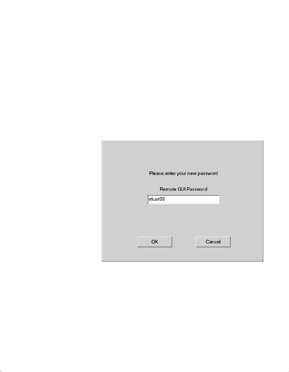
Chapter 2 Basic Operations
Setting up the FST-2802
Specifying a
Remote GUI
password
If you intend to use the Remote GUI to control the TestPad from a
remote PC or laptop, you must specify a Remote GUI password to
secure access to the TestPad. Each time you initiate a Remote GUI
session, you’ll be required to enter the password.
The default Remote GUI password is acterna.
To specify a Remote GUI password
1 Select Tools > Connectivity.
The Connectivity Menu appears.
2 Select Remote GUI.
The Remote GUI Password dialog box appears.
Specifying date
and time settings
3 In Remote GUI Password, type a password using up to eight
characters, and then select OK.
The Connectivity Menu appears, and the Remote GUI password is set.
By default, the TestPad presents dates on print files using a standard
MM/DD/YYYY format, and time using a standard Hour:Minute:Second
format. You can change the date, time, or format at any time.
FST-2802 TestPad User’s Guide Revision A
35
Page 62
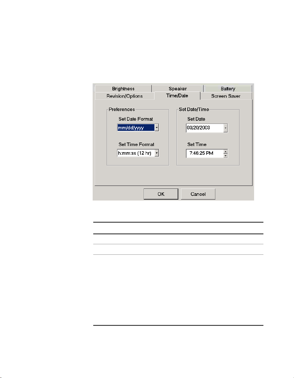
Chapter 2 Basic Operations
Setting up the FST-2802
To specify date and time settings
1 Select Tools > TestPad Settings.
A series of setup tabs appears.
2 Select Time/Date.
3 To specify the settings, do the following:
To… Do t h i s …
Set the date format In Set Date Format, select a date format.
Set the time format In Set Time Format, select a time format.
Set the date Select the arrow to the right of the Set Date
field. A calendar appears. Do one of the following:
– To select a date from the month and
year displayed, simply select the date.
– To navigate through the calendar to
select a date from a different month or
year, use the arrows at the top of the
calendar to display the month, and then
select the date.
36 FST-2802 TestPad User’s Guide Revision A
Page 63

Chapter 2 Basic Operations
Setting up the FST-2802
To… Do t h i s …
Set the time In Set Time, select the hour, minutes, or
seconds you want to modify, and then select
the up or down arrow to the right of the field
to increase or decrease the value in increments of one.
4 Select OK.
The date and time settings are specified.
Setting up the
screen saver
The TestPad is equipped with a screen saver. You can setup the
TestPad to use the screen saver, or you can disable the screen saver
entirely. If you use the screen saver, you can specify how much time
must elapse before the TestPad displays the screen saver, and you
can optionally display a blank screen or a scrolling message whenever
the screen saver appears.
To set up the screen saver
1 Select Too l s > TestPad Settings.
A series of setup tabs appears.
FST-2802 TestPad User’s Guide Revision A
37
Page 64
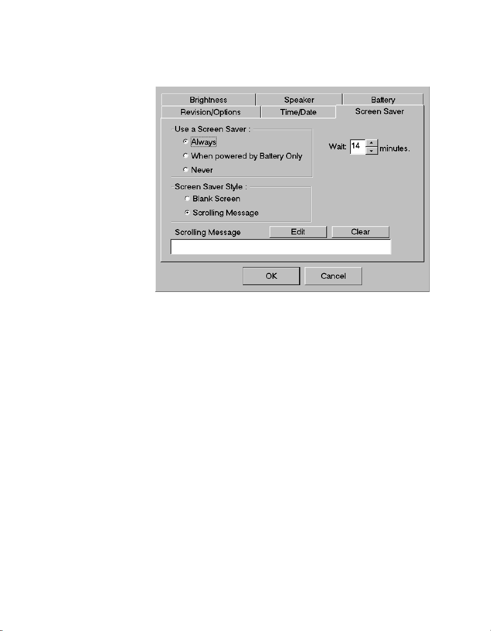
Chapter 2 Basic Operations
Setting up the FST-2802
2 Select Screen Saver.
3 If you do not want to use a screen saver, under User a Screen
Saver, select Never, and then proceed to step 4.
If you do want to use a screen saver, do the following:
a Select an option for Use a Screen Saver.
b Select a screen saver style: Blank Screen or Scrolling
Message.
c If you selected Scrolling Message, select Edit to display the
Enter new message dialog box, and then type the message.
Select OK to return to the Screen Saver tab.
d Select the time to elapse before the screen saver appears.
4 Select OK.
The screen saver is set up.
Setting the screen
brightness
38 FST-2802 TestPad User’s Guide Revision A
You can control the screen brightness on the TestPad. Higher brightness provides greater clarity when viewing the user interface.
Page 65
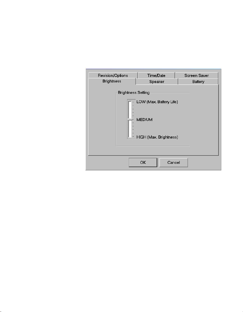
To set the screen brightness
1 Select Too l s > TestPad Settings.
A series of setup tabs appears.
2 Select Brightness.
Chapter 2 Basic Operations
Setting up the FST-2802
Specifying
speaker settings
3 Under Brightness Setting, drag the pointer to the level of bright-
ness you want to use for the screen.
4 Select OK.
The screen brightness is set.
You can control the speaker volume on the TestPad or mute the
speaker entirely. You can also setup the TestPad to beep whenever
you insert or remove a PCMCIA card or whenever you select a button
on the user interface.
To specify speaker settings
1 Select Too l s > TestPad Settings.
A series of setup tabs appears.
FST-2802 TestPad User’s Guide Revision A
39
Page 66
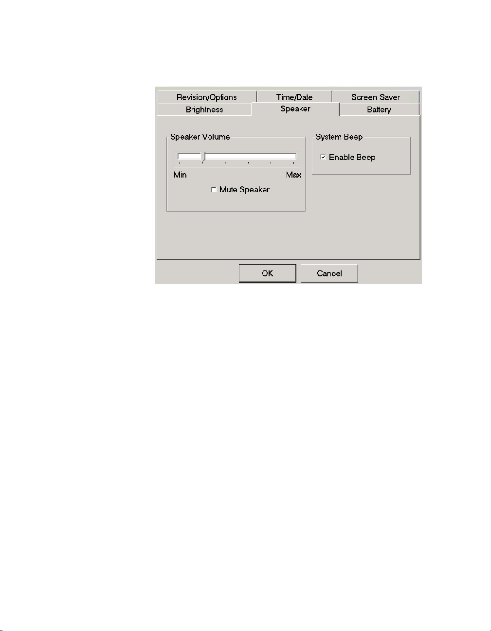
Chapter 2 Basic Operations
Setting up the FST-2802
2 Select Speaker.
3 To control the speaker’s volume, do one of the following:
– If you want to adjust the speaker volume, under Speaker
Volume, drag the pointer to the level of volume you want the
speaker to use.
– If you want to mute the speaker volume entirely, select Mute
Speaker.
4 To set up the TestPad to beep whenever you insert or remove a
PCMCIA card or select a button on the user interface, select
Enable Beep.
5 Select OK.
The speaker settings are specified.
Loading options
and software
upgrades
40 FST-2802 TestPad User’s Guide Revision A
If you purchase options or obtain an FST-2802 or UIM software
upgrade, you receive a PCMCIA card with the software for the options
or upgrade. Loading options or FST-2802 software upgrades involves
inserting the PCMCIA card into a PCMCIA card slot, loading the software, and then waiting for the TestPad to reboot. Loading options is
typically a quick process; loading an FST-2802 software upgrade
takes longer.
Page 67
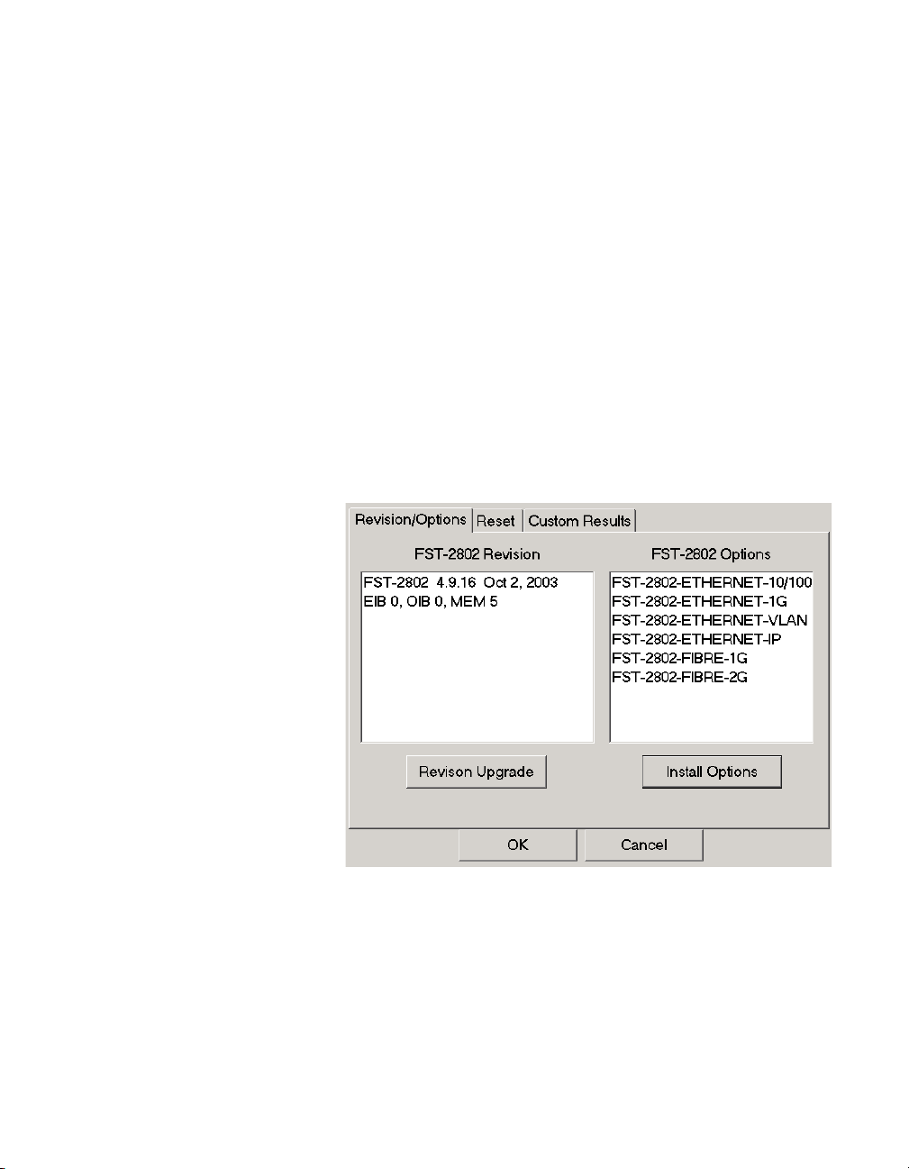
Chapter 2 Basic Operations
Setting up the FST-2802
For instructions on loading UIM software upgrades, refer to the
upgrade instructions provided with the upgrade card.
Loading options
You can load options from a single PCMCIA card or from two separate
PCMCIA cards simultaneously.
To load options
1 Insert the PCMCIA card or cards with the options in a PCMCIA
card slot.
2 Select the Tools button, and then do one of the following:
– To load UIM options, select TestPad Settings, and then select
the Revisions/Options tab.
– To load FST-2802 settings, select FST-2802 Settings. The
Revisions/Options tab appears.
Currently installed options on the TestPad appear under TestPad
Options or FST-2802 Options.
3 Select Install Options.
FST-2802 TestPad User’s Guide Revision A
41
Page 68
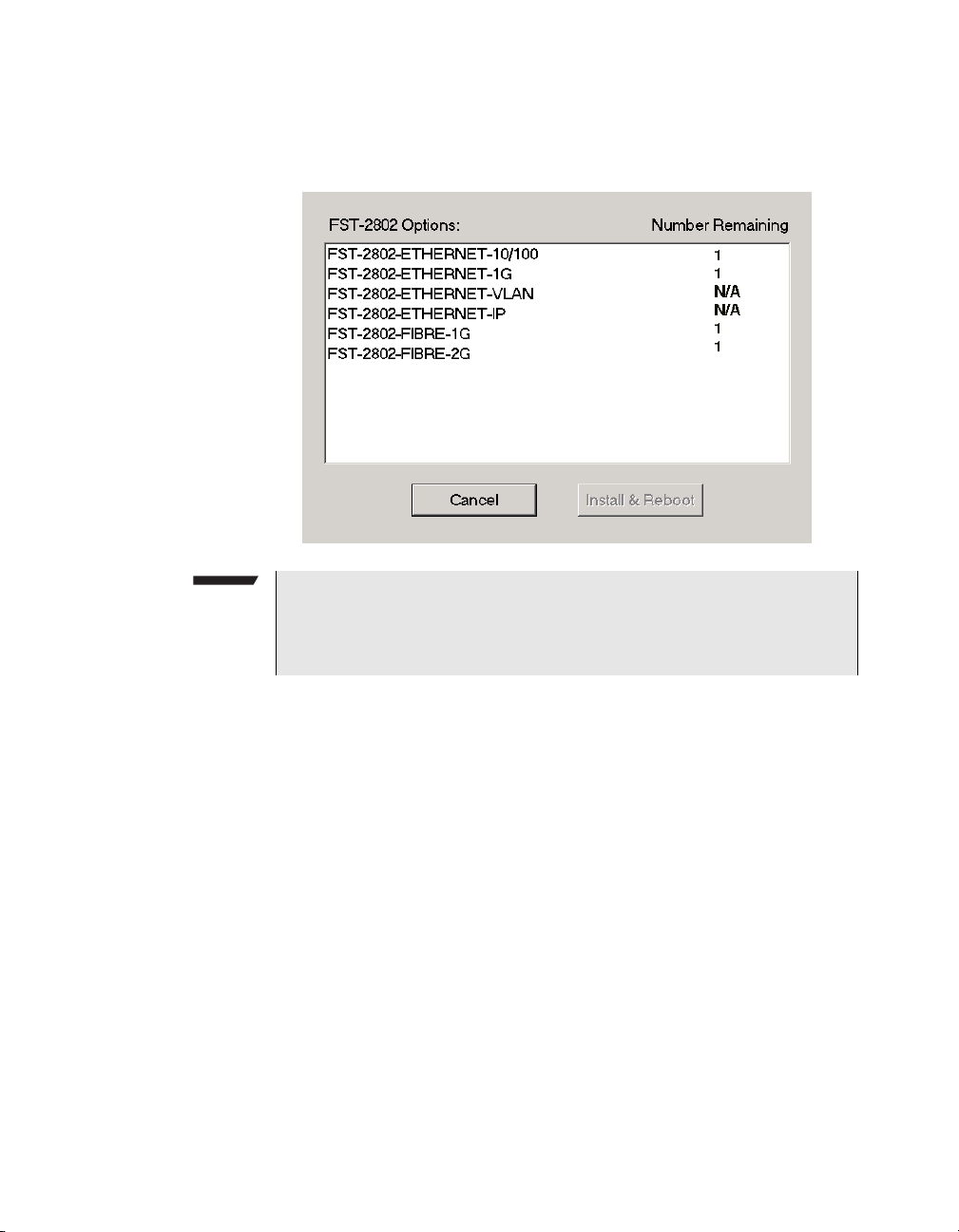
Chapter 2 Basic Operations
Setting up the FST-2802
The Options Installation dialog box appears, listing the options
available on the PCMCIA card (or cards).
NOTE:
If you inserted two PCMCIA optioning cards into the TestPad, and
both cards include the same option, the option appears twice in the
list of options.
The Number Remaining field indicates the remaining copies of the
option which are available for installation. Each time you install an
option, the TestPad decreases the number remaining by one.
4 Select the option or options you want to install.
5 Select Install & Reboot.
42 FST-2802 TestPad User’s Guide Revision A
Page 69
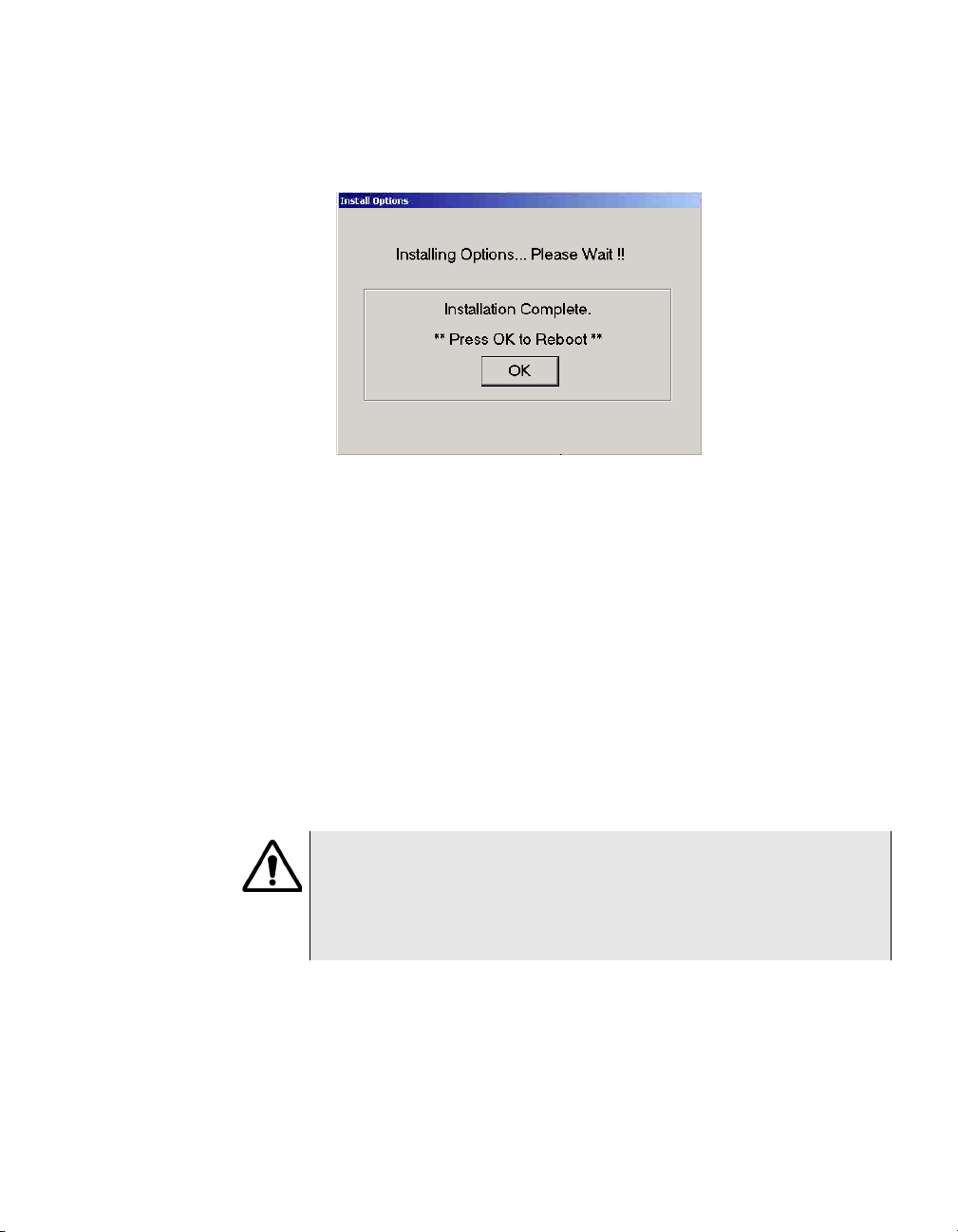
Chapter 2 Basic Operations
Setting up the FST-2802
The TestPad installs the options, and then the Install Options
dialog box appears.
6 Select OK to acknowledge the message.
The TestPad reboots and the options are available.
Loading an FST-2802
software upgrade
Before you load an FST-2802 software upgrade, you must power the
TestPad using an AC adapter. We also recommend using a battery
charged to at least 50 percent capacity as a backup power supply.
If you insert a PCMCIA card into the TestPad with an FST-2802 software upgrade before you turn the TestPad on, the TestPad automatically detects a new version of the software when it boots up and asks
if you want to upgrade the software.
Loading the upgrade typically takes about forty-five minutes.
CAUTION: DAMAGE TO TESTPAD
When you load a software upgrade, the TestPad deletes all existing
application module software, automatically reboots, and then loads
the upgrade. Therefore, if power is interrupted during the course of
the upgrade, the TestPad may require factory service to operate.
To load a software upgrade
1 Insert the software upgrade card into a PCMCIA card slot.
2 Connect the AC adapter to the DC IN jack (located on the bottom
panel of the TestPad), and then plug it in to an electrical outlet.
FST-2802 TestPad User’s Guide Revision A
43
Page 70
Chapter 2 Basic Operations
Setting up the FST-2802
3 Turn the TestPad power ON.
The TestPad displays a series of boot-up messages. When the
boot-up is complete, a dialog box appears informing you that a
newer version of the application module software has been
detected and prompts you to upgrade the software.
4 Select OK.
The TestPad displays the following warning:
WARNING
DO NOT TURN POWER OFF AT THIS TIME.
Transfer of system files in progress. System may
require factory service if power fails during
transfer.
At the bottom of the screen, a box appears which shows the
percentage of each file transferred during the upgrade.
NOTE:
Between file transfers, a message appears informing you that the
TestPad is preparing the system for another file transfer and advising you to be patient. It may take a couple of minutes for the TestPad to begin transferring the next file.
After the last file is transferred, the TestPad reboots.
The software upgrade is loaded.
NOTE:
If you insert a PCMCIA upgrade card after you turn the TestPad on,
you can select Tools > FST-2802 Settings to display the Revisions/
Options tab, and then select the Revision Upgrade option to load
the upgrade.
44 FST-2802 TestPad User’s Guide Revision A
Page 71
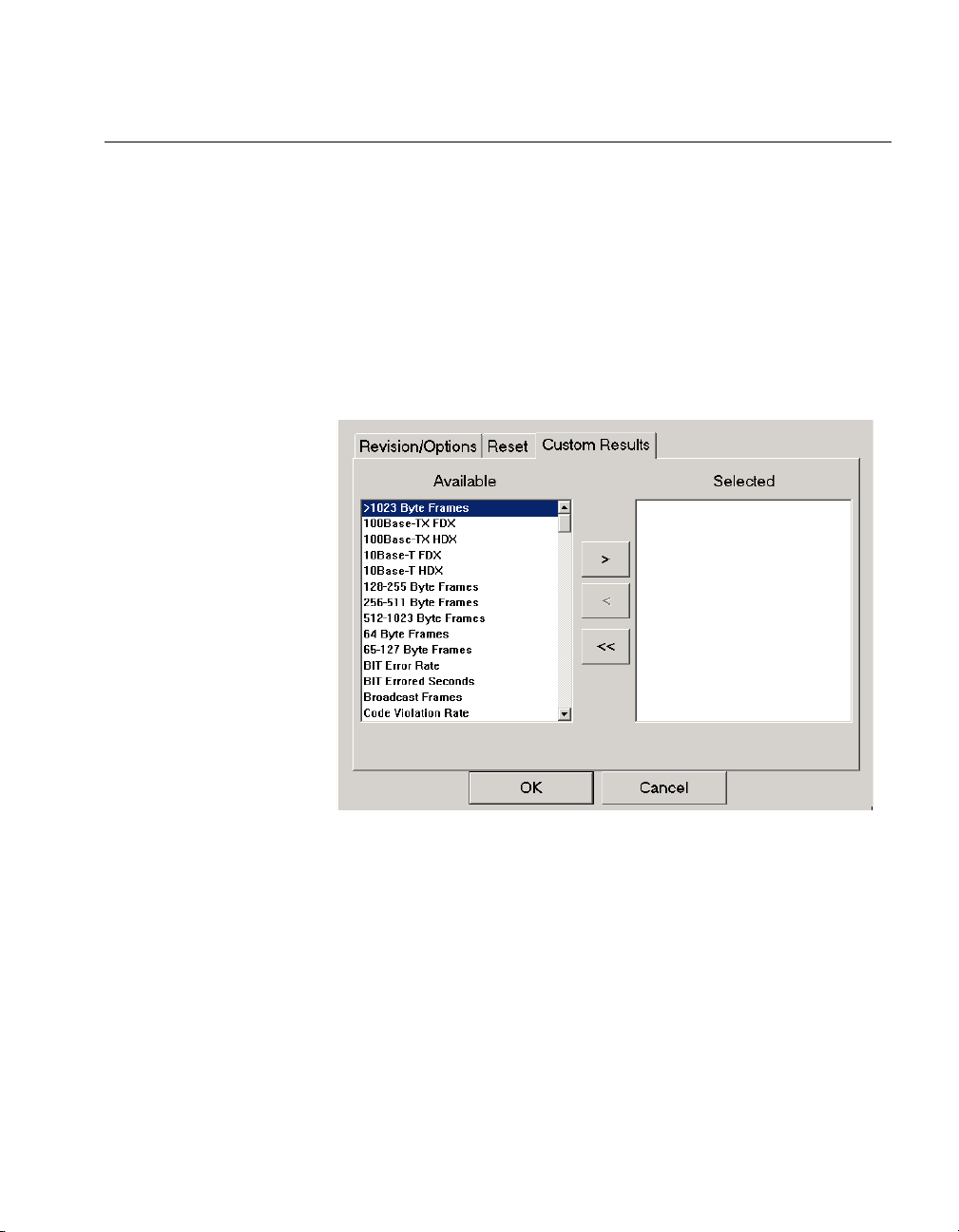
Defining the Custom result category
You can define a Custom result category with results from a variety of
categories. This allows you to quickly view the results on a single result
pane without navigating through each individual category.
To define the Custom result category
1 Select Too l s > FST-2802 Settings.
The Reset tab appears.
2 Select the Custom Results tab.
Chapter 2 Basic Operations
Defining the Custom result category
3 Select the results you want to view in the Custom category from
the Available list, and then do one of the following:
–Use the > and < arrows to move single results between the
Available and Selected list boxes.
–Use the << arrows to move all selected results back to the
Available list box.
4 Select OK to return to the main screen.
Results are selected for the Custom result category.
FST-2802 TestPad User’s Guide Revision A
45
Page 72
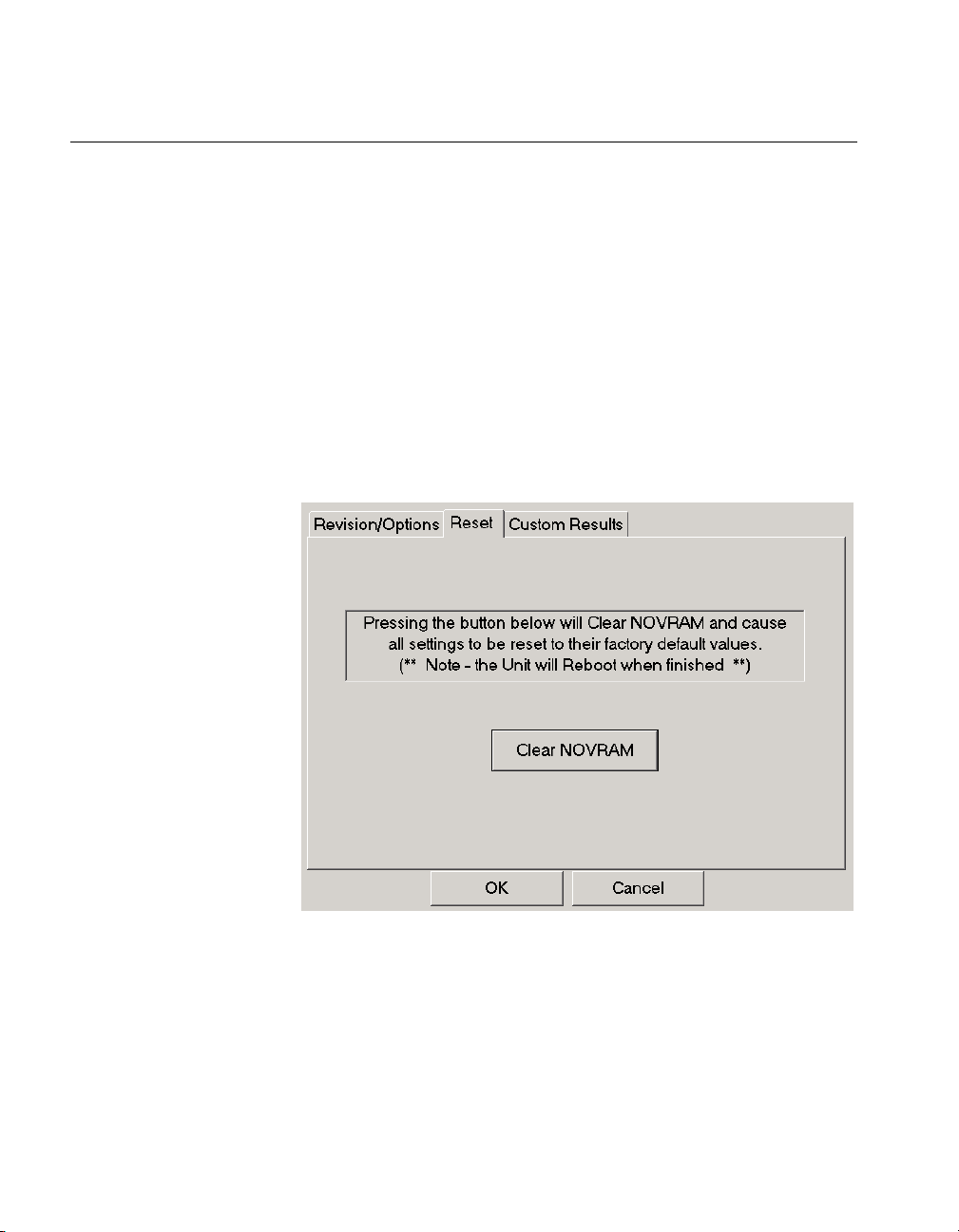
Chapter 2 Basic Operations
Restoring factory defaults
Restoring factory defaults
You can restore the FST-2802 settings to the factory defaults using the
Clear NOVRAM feature. When you clear NOVRAM, the TestPad
restores the following settings for each port:
– Test applications. All test applications for the FST-2802 are
restored to their default values.
– Print Management settings. The print management settings are
restored to their default values.
To restore factory defaults
1 Select Tools > FST-2802 Settings.
The Reset tab appears.
2 Select Clear NOVRAM.
The TestPad restores the FST-2802 settings back to the factory
defaults. This typically takes about ten seconds, and then a
message appears informing you that the settings are restored.
3 Select OK to acknowledge the message.
The TestPad reboots, and the settings are restored.
46 FST-2802 TestPad User’s Guide Revision A
Page 73
Chapter 2 Basic Operations
Printing test configurations, test results, and histograms
Printing test configurations, test results, and histograms
You can print test configurations, test results, and histograms from the
TestPad. Printing involves connecting a printer, and then specifying
print parameters such as the print mode, print type, and print event
triggers. If you connected a serial printer, you must also configure the
printer.
After you specify the print parameters, you are ready to generate print
output. When you generate print output, you can do the following:
– Encrypt the output to ensure the integrity of the data you sent to
your supervisor or Technical Support department.
– Send the output directly to a printer.
– Store the output in a file on the TestPad to print at a later time.
– Automatically e-mail the output. For example, if you want your
Technical Support department to review your test results, you can
set up the TestPad to automatically e-mail the results to the
department.
Printing to text
files
NOTE:
If your FST-2802 has two ports, and both ports are active, the TestPad generates output for each active port. For example, if you are
testing using both Port 1 and Port 2, print output of test results will
list test results for Port 1 first, and then the test results for Port 2.
The following sections introduce you to some basic concepts about
printing, and then describe how to connect a printer, configure a serial
printer, specify print parameters, and print your print files.
The first time you generate print output, by default, the TestPad
appends the output to the default print file, default.txt in the
following directory:
Acterna\Files\FST-2802
FST-2802 TestPad User’s Guide Revision A
47
Page 74

Chapter 2 Basic Operations
Printing test configurations, test results, and histograms
When you specify print parameters for the output, you can do the
following:
– You can clear the output in the default.txt file, and then
repopulate the file with new output.
– You can direct the print output to a new or different .txt file.
Encrypting print
files
Sending an encrypted
print file
Reading an encrypted
print file
You can optionally encrypt print files by selecting the Encrypt print file
option on the Print Setup tab. When you generate an encrypted print
file, the TestPad creates two files: the standard text (.txt) file, and
an additional encrypted (.crp) file. For example, if you generate a
print file named “1GPatt”, the TestPad creates the following files:
– 1GPatt.txt
– 1GPatt.crp
You can send an encrypted print file to your supervisor or Technical
Support department by selecting the option to automatically email the
file after it is generated (see “Sending e-mail” on page 62) or using
FTP (see “Managing files” on page 71).
The first time you send an encrypted (.crp) file to your supervisor or
Technical Support department, you need to send the decrypt.exe
executable which enables them to read the encrypted file. The file is
located at:
[SYS] Z:/decrypt.exe
To read an encrypted print file, you must launch decrypt.exe using
the print filename as a parameter. For example, if the encrypted file’s
name is 1GPatt.crp, use the following command to launch the
executable:
decrypt.exe 1GPatt.crp
The executable converts the encrypted (.crp) file to a text (.txt) file.
48 FST-2802 TestPad User’s Guide Revision A
Page 75

Chapter 2 Basic Operations
Printing test configurations, test results, and histograms
Print modes
Print types
Print event
triggers
Connecting a
printer
Print modes identify the way you want to generate print output: manually, at timed intervals, or when a test ends. You specify the print mode
for your print output in the Print Mode field of the Setup tab.
Print types represent the type of information you want to include in the
print output (all test results, test results for a selected group of categories, test configurations, or histograms). When you specify print
parameters, you specify the print type for your print output in the Print
Type field of the Setup tab.
NOTE:
To print test configurations (controls) and histograms, you must
generate print output in manual mode.
Print event triggers cause the TestPad to generate print output whenever the event (a result change, test restart, or a remote user connects
or disconnects to the TestPad) occurs. The event output includes a
date and time stamp indicating when the event occurred.
The USB/Serial port, located on the top panel, is used to connect the
standard Y cable provided with the TestPad. The Y cable provides a
USB connector and a serial connector, allowing you to connect a USB
printer, such as the 2000-USB-PRINTER, or serial printer, such as the
PR-40B to the TestPad.
To connect the printer
1 Turn on the TestPad.
2 Attach the Y cable to the USB/Serial port.
FST-2802 TestPad User’s Guide Revision A
49
Page 76
Chapter 2 Basic Operations
Printing test configurations, test results, and histograms
3 Do one of the following:
– If you are connecting a serial printer, using the supplied printer
cable, connect the DB-9 female connector on the printer cable
to the serial connector on the Y cable, and then connect the
DB-9 male connector on the printer cable to the printer.
– If you are connecting a USB printer, using the supplied printer
cable, connect the cable to the USB connector of the Y cable,
and then connect the other end of the printer cable to the
printer.
NOTE:
When connecting to the PR-40B serial printer, use the printer cable
provided with the printer. Operability of the printer port cannot be
guaranteed if you use a cable longer than 3 meters.
By default, the baud rate for the serial printer interface is 9600, and the
parity method is none. If you need to change these settings, see
“Configuring a serial printer” on page 50.
Configuring a
serial printer
50 FST-2802 TestPad User’s Guide Revision A
Configuring a serial printer involves specifying the printer device, and
then specifying the communications parameters, such as the baud
rate, data bits, parity, stop bits, and flow control.
To configure a printer
1 Select Tools > Connectivity.
The Connectivity Menu appears.
2 Select Serial Printer.
Page 77
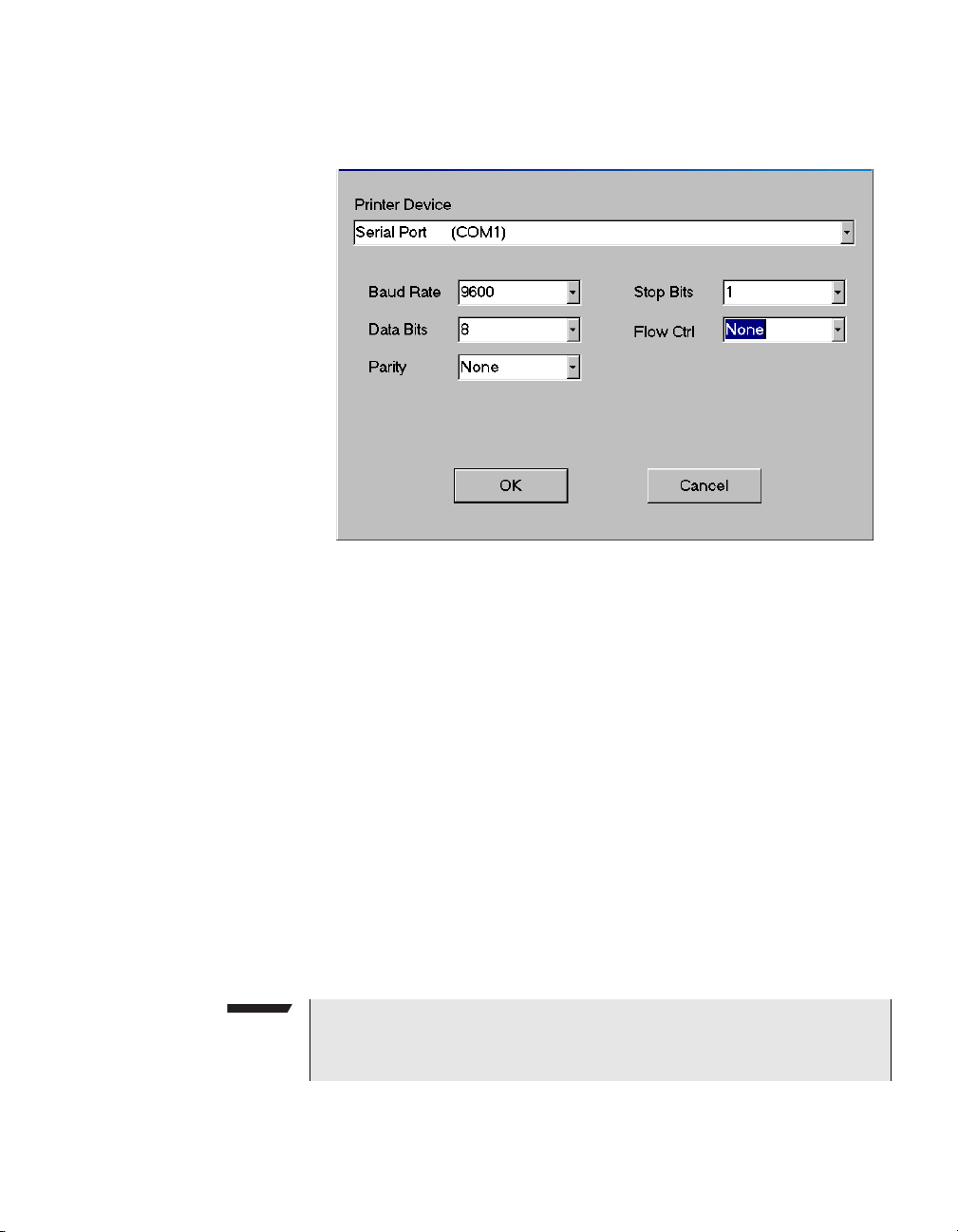
Chapter 2 Basic Operations
Printing test configurations, test results, and histograms
The Printer Configuration dialog box appears.
3 If you have either a serial card or a Y cable connected to the
TestPad, the serial printer device available appears automatically
under Serial Printer Device.
If you have both a serial card and a Y cable connected to the
TestPad, under Serial Printer Device, select Serial Card to
connect via a card, or Serial Port to connect via the serial port on
the Y cable.
4 Specify the settings for the printer, and then select OK. Default
values for each of the settings are as follows:
– Baud rate: 9600
– Data bits: eight
– Parity: None
– Stop bits: None
– Flow control: None
The printer is configured.
NOTE:
You can also use the Configure option on the Setup tab to configure
a printer when you specify print parameters.
FST-2802 TestPad User’s Guide Revision A
51
Page 78
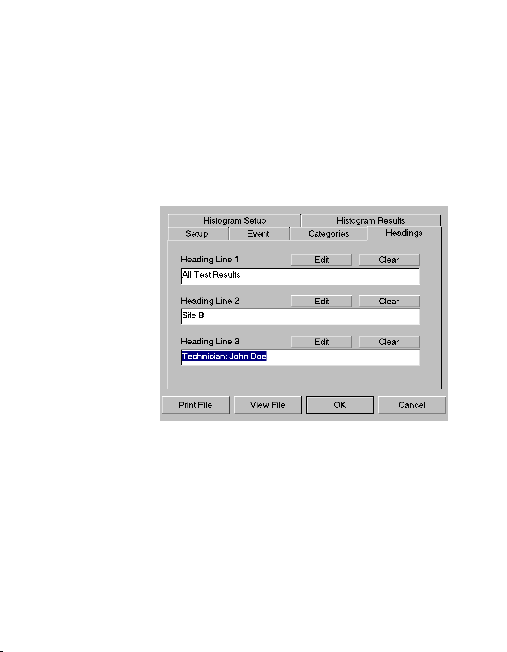
Chapter 2 Basic Operations
Printing test configurations, test results, and histograms
Creating a
heading for print
output
You can create a custom heading for print output. These headings are
particularly helpful if you append print output to the same print file each
time you print. By defining unique headings for your print output, you
can easily identify the output associated with each test.
To create a heading
1 Select Tools > Print Management.
A series of print management tabs appear.
2 Select Headings.
3 In Heading Line 1, type the first heading you want to appear on
the print file.
4 If you want a second and third heading, type the headings in the
corresponding fields.
5 Select Setup to return to the Setup tab, or OK to return to the
main screen.
The heading is created and will appear above your print output.
52 FST-2802 TestPad User’s Guide Revision A
Page 79
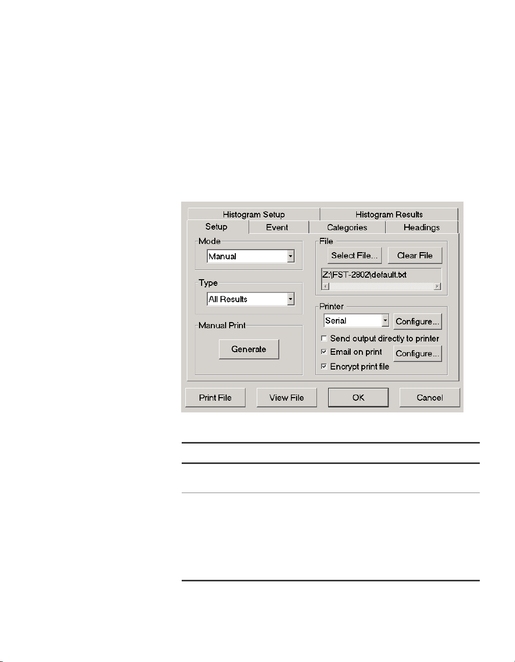
Chapter 2 Basic Operations
Printing test configurations, test results, and histograms
Generating print
output
Generating print output involves specifying the print mode, specifying
a print type (and defining print type parameters, if necessary), and
then selecting the Generate button to generate the print output immediately, or scheduling the TestPad to automatically generate print
output.
To generate print output
1 Select Too l s > Print Management.
The Setup tab appears.
2 In Mode, select one of the following print modes:
Select To…
Manual Manually generate print output. Proceed to
step 4.
Timed (Repeating) Generate print output at regularly scheduled
intervals.
For example, if you want the TestPad to gen-
erate test results output every ten minutes,
select the Timed (Repeating) print mode,
and then proceed to step 3 to specify the
interval between generated print output.
FST-2802 TestPad User’s Guide Revision A
53
Page 80
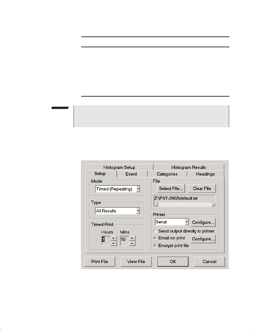
Chapter 2 Basic Operations
Printing test configurations, test results, and histograms
Select To…
Timed (Test End) Generate print output whenever a test ends.
NOTE:
You must select Manual mode to print test configurations (controls)
and histograms.
If you selected Timed (Repeating) or Timed (Test End), fields
appear on the Setup tab which allow you to specify the interval
between TestPad generated print output or the amount of time that
will pass after a test restart before a test ends.
For example, if you want the TestPad to generate test results output when a test ends in
thirty minutes, select the Timed (Test End)
print mode, and then proceed to step 3 to
specify the amount of time after a test restart
(thirty minutes) that will pass before the test
ends.
3 In Hours and Mins, type the hours or minutes, or select the up
and down arrows next to the fields to increase or decrease the
displayed value.
54 FST-2802 TestPad User’s Guide Revision A
Page 81
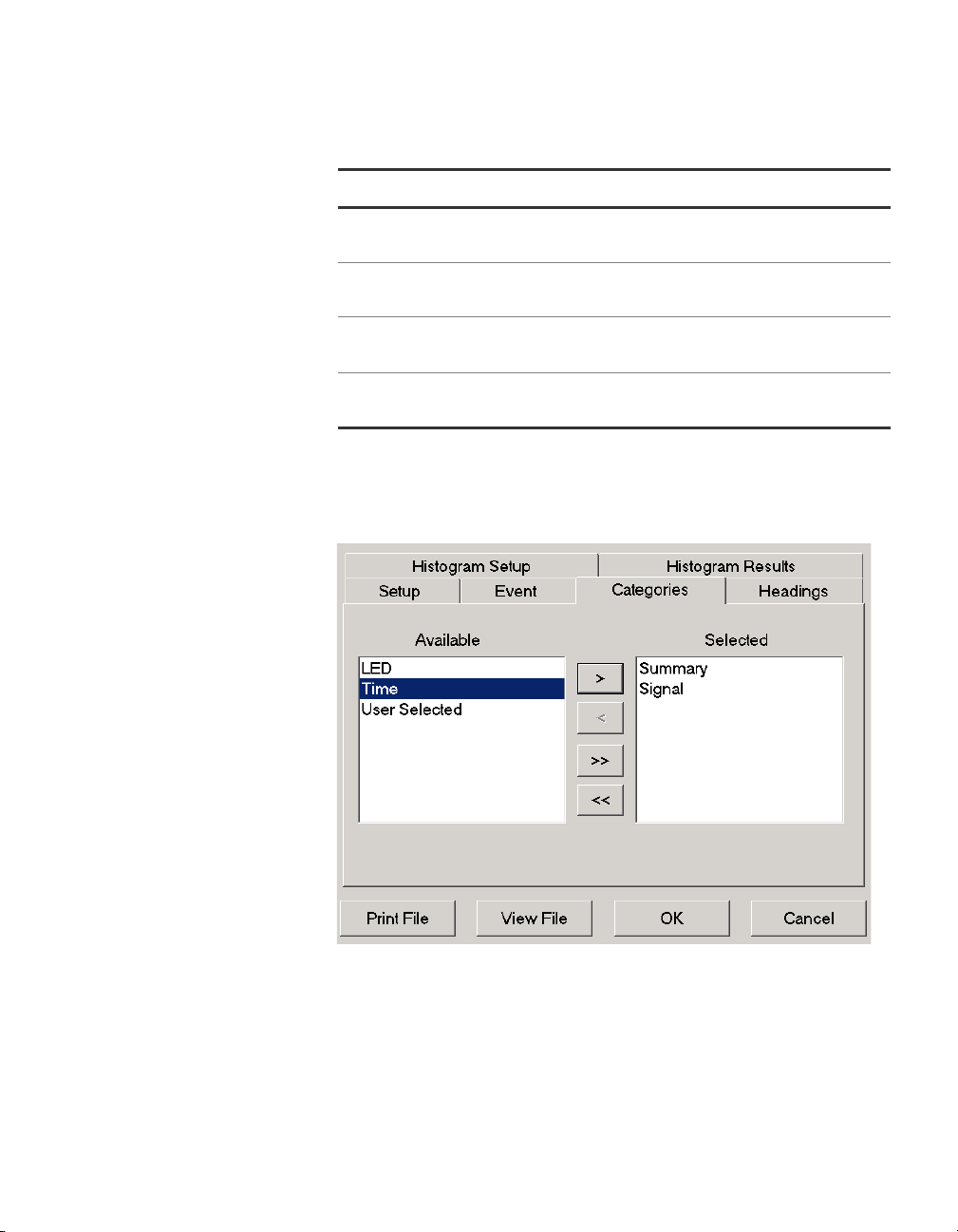
Chapter 2 Basic Operations
Printing test configurations, test results, and histograms
4 In Typ e , select one of the following print types:
Select… To…
All Results Print all test results for a test. Proceed to
step 7.
Selected Categories Print test results for a specific group of cate-
gories. Proceed to step 5.
Controls Print the configuration for a test. Proceed to
step 7.
Histogram Print specific results based upon the histo-
gram configuration. Proceed to step 6.
5 If you chose Selected Categories as the print type in step 4, select
the Categories tab to choose the categories for the print output,
and then do the following:
a To select categories, use the > and < arrows to move single
categories between the Available and Selected list boxes, or
use the >> and << arrows to move all categories.
b Proceed to step 7.
FST-2802 TestPad User’s Guide Revision A
55
Page 82

Chapter 2 Basic Operations
Printing test configurations, test results, and histograms
6 If you selected Histogram as the print type in step 4, see “Setting
up a histogram” on page 57 for instructions on setting up histo-
gram output, and then proceed to step 7.
7 Optional. If you want the TestPad to generate print output when-
ever you restart a test, a result changes, or a remote user
connects or disconnects to the TestPad, select the Event tab, and
then select Test Restart, Result Change, or Remote User
Connect/Disconnect.
8 Return to the Setup tab.
9 Optional. If you want to clear the displayed print file, or direct the
print output to a new or different file, do one of the following:
To… Do this…
Clear the displayed
print file, and then repopulate the file with
new output
Direct the print output
to a new file
Direct the print output
to a different file
Select
Clear File.
Choose Select File to display the File Management dialog box, and then do the following:
– Select the File Name field. An Acterna
keypad appears.
– Type the new file name.
–Select OK to return to the Setup tab.
Choose Select File to display the File Management dialog box, and then do the following:
– Under File Name, select the file you
want to direct the output to.
–Select OK to return to the Setup tab.
10 Optional. If you want to send the output directly to a printer, select
Send output directly to a printer, and then select the printer you
want to direct the output to (Serial or USB).
11 Optional. If you want to email the output when it is generated,
select Email on print. See “Sending e-mail” on page 62 for
instructions on sending e-mail from the TestPad.
56 FST-2802 TestPad User’s Guide Revision A
Page 83
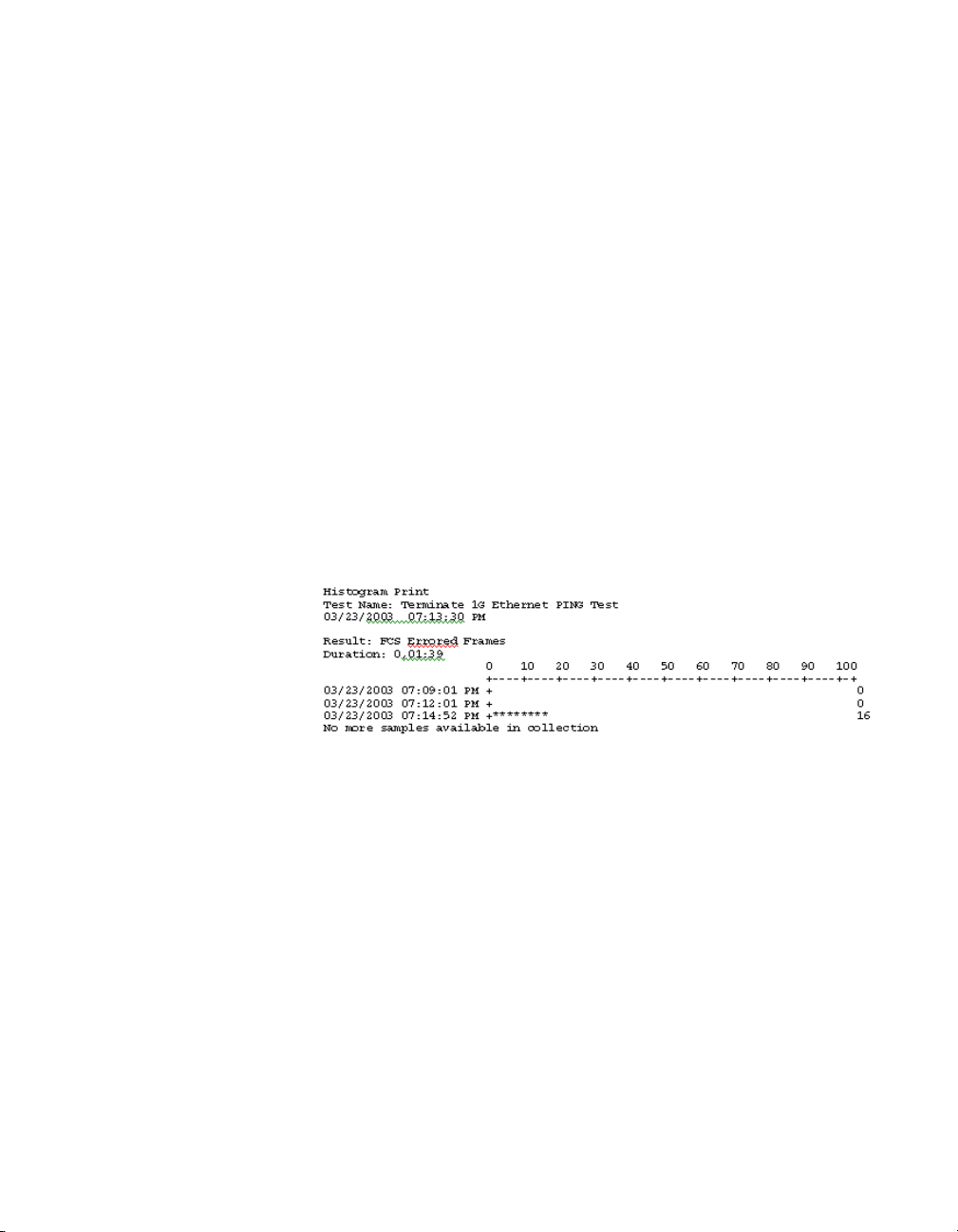
Chapter 2 Basic Operations
Printing test configurations, test results, and histograms
12 Optional. If you want to encrypt the output, select Encrypt print
file.
13 Select Generate or Print File.
14 If you want to store the print settings you specified, select OK to
return to the Main Screen. If you do not want to store the print
settings, select Cancel.
If you sent the print output directly to a printer, the TestPad prints the
output and sends the output to the .txt file you specified. If you sent
the print output to a file, the output is stored in the .txt file to be
printed at a later time.
Setting up a
histogram
A histogram is print output of test results in a bar graph format. Histograms enable you to quickly identify spikes and patterns of errors over
a specific interval of time. Figure 11 shows a sample Histogram
printout.
Figure 11 Histogram printout
Each time you run a test, the TestPad automatically accumulates data
for a histogram in the histogram buffer. Whenever you start a new test,
the histogram buffer clears, and then populates with data from the new
test.
You can choose which results to collect for the histogram print output,
and when the TestPad will collect the samples. If your FST-2802 has
two ports and you are running tests on both ports, the TestPad will
create a separate histogram for each test.
To set up histogram print output
1 Select the Tools button.
The Tools Menu appears.
FST-2802 TestPad User’s Guide Revision A
57
Page 84
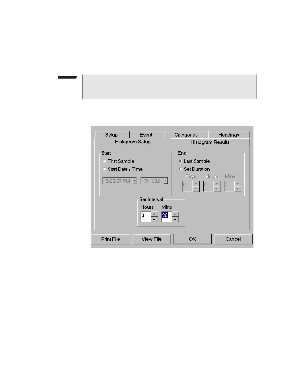
Chapter 2 Basic Operations
Printing test configurations, test results, and histograms
2 Select Print Management.
The Setup tab appears.
3 In Mode, select Manual.
NOTE:
You cannot print histograms in Timed (Repeating) or Timed (Test
End) modes.
4 In Type, select Histogram.
5 Select the Histogram Setup tab.
6 Under Start, do one of the following:
–Select First Sample to select all available data for the print
output from the moment the test starts.
–Select Start Date/Time to specify the start data and time for
data collection for the histogram. If you select this option, you
must type the date and time the TestPad will start collecting
data in the associated fields.
58 FST-2802 TestPad User’s Guide Revision A
Page 85
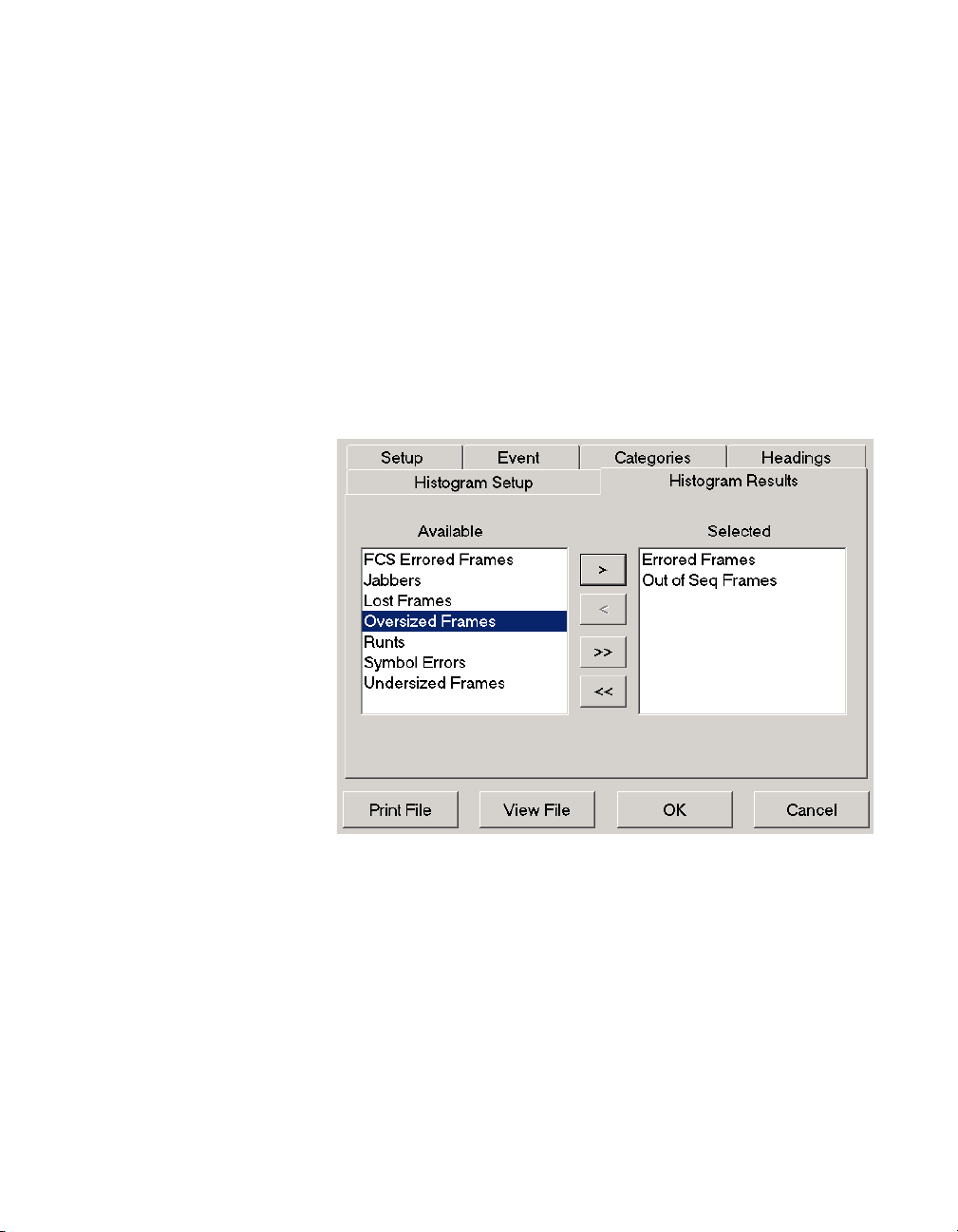
Chapter 2 Basic Operations
Printing test configurations, test results, and histograms
7 Under End, do one of the following:
–Select Last Sample to select all available data for the print
output from the moment you select Generate to generate
output for the histogram.
–Select Set Duration to specify a duration of time during which
the TestPad will collect data for the histogram. If you select this
option, you must type the days, hours, and minutes for the
duration in the associated fields.
8 Under Bar Interval, type the hours and minutes represented in
each histogram bar.
9 Select the Histogram Results tab.
10 To select the result categories for the histogram, do one of the
following:
a Select the categories you would like to include in the print
output. Use the > and < arrows to move single categories
between the Available and Selected list boxes. Use the >> and
<< arrows to move all categories.
b Select OK.
FST-2802 TestPad User’s Guide Revision A
59
Page 86
Chapter 2 Basic Operations
Printing test configurations, test results, and histograms
NOTE:
The result categories available for a histogram depend on the current test configuration. Each time you configure a test using the
same settings, the histogram categories you selected previously for
the configuration are automatically available; however, you can edit
the categories at any time.
11 In Printer, select the printer you want to direct the histogram output
to (Serial or USB).
12 Optional. If you want to send the histogram directly to a printer,
select Send output directly to a printer.
13 Optional. If you want to email the histogram when it is generated,
select Email on print. See “Sending e-mail” on page 62 for
instructions on sending e-mail from the TestPad.
14 Select Generate or Print File.
If you sent the histogram directly to a printer, the TestPad prints the
histogram and sends the output to the .txt file you specified. If you
sent the histogram to a file, the output is stored in the .txt file to be
printed at a later time.
Viewing stored
print files
60 FST-2802 TestPad User’s Guide Revision A
You can view stored print files using the View File button on the Setup
tab.
NOTE:
You can also view stored print files from the File Management dialog box. See “Viewing, running, deleting, or renaming a file” on
page 75.
To view a stored print file
1 Select Tools > Print Management.
The Setup tab appears.
2 Under File, the most recently created print file appears. Do one of
the following:
– To view the displayed print file, proceed to step 3.
– To view a different print file, choose Select File, and then
select the print file you want to view.
Page 87

Chapter 2 Basic Operations
Using the on-screen keyboard
3 Select View File.
The print file appears in the Print Viewer dialog box.
Printing a stored
print file
You can print stored print files using the Print File button on the Setup
tab.
To print a stored print file
1 Select Too l s > Print Management.
The Setup tab appears.
2 Under File, the most recently created print file appears. Do one of
the following:
– To print the displayed print file, proceed to step 3.
– To print a different print file, choose Select File, and then
select the print file you want to print.
3 Select Print File.
The print file is printed.
Using the on-screen keyboard
The FST-2802 provides an on-screen keyboard, which you can use to
type information in the active window when you use the Web browser,
use the VNC Viewer, or emulate a VT100 terminal using the TestPad.
NOTE:
You do not need to use the on-screen keyboard to type data in the
FST-2802 user interface; a virtual keyboard is available whenever
typing is required. If you need to type a lot of information, we recommend using a USB keyboard.
To use the on-screen keyboard
1 Press the Keyboard key.
The on-screen keyboard appears.
2 In the active window, tap the field you need to type in.
FST-2802 TestPad User’s Guide Revision A
61
Page 88
Chapter 2 Basic Operations
Sending e-mail
Sending e-mail
3 Tap the keys on the on-screen keyboard to type text in the field. To
type a symbol, tap the Shift key. The numeric keys change to
symbol keys. Type the symbol. The symbol keys change back to
numeric keys. You must tap the Shift key each time you need to
type a symbol.
After you launch the on-screen keyboard, you can:
– Move the keyboard to a different location by dragging the title bar.
– Minimize the keyboard.
– Maximize the keyboard by pressing the Keyboard key.
– Type all capital letters by first tapping the Caps Lock key.
NOTE:
To optimize performance of the TestPad, secondary features of the
on-screen keyboard such as online help have been disabled.
If you purchased the Networking option, you can send e-mail from the
TestPad. Before you send e-mail, you must establish a modem dialout, modem dial-in, or LAN connection to connect to a Simple Mail
Transfer Protocol (SMTP) server.
When you compose e-mail, you can:
– Populate the Address Book with e-mail addresses.
– Type messages.
– Attach print files containing test results, test configurations, or
histogram data.
NOTE:
The first time you compose an e-mail on the TestPad, you must
specify the address for an SMTP server. Internet Service Providers
(ISPs) typically provide an SMTP server. After you specify the
SMTP server for the first e-mail, the TestPad stores the server
address and provides it automatically each time you compose a
new e-mail.
62 FST-2802 TestPad User’s Guide Revision A
Page 89
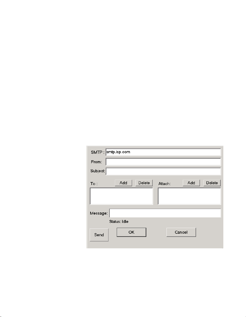
Chapter 2 Basic Operations
Sending e-mail
To send an e-mail
1 Establish a modem dial-out, modem dial-in, or LAN connection
from the TestPad to a network for Internet access.
– For detailed instructions on establishing a modem dial-out
connection, see “Establishing modem dial-out connections” on
page 83.
– For detailed instructions on establishing a modem dial-in
connection, see “Establishing modem dial-in connections” on
page 85.
– For detailed instructions on establishing a LAN connection, see
“Establishing LAN connections” on page 87.
2 On the TestPad, select the Tools > Connectivity.
The Connectivity Menu appears.
3 Select Email.
The E-mail dialog box appears.
4 In SMTP, type the SMTP server address. The SMTP server
address is typically one of the following:
– smtp.internet provider name.com
– smtp.internet provider name.net
FST-2802 TestPad User’s Guide Revision A
63
Page 90
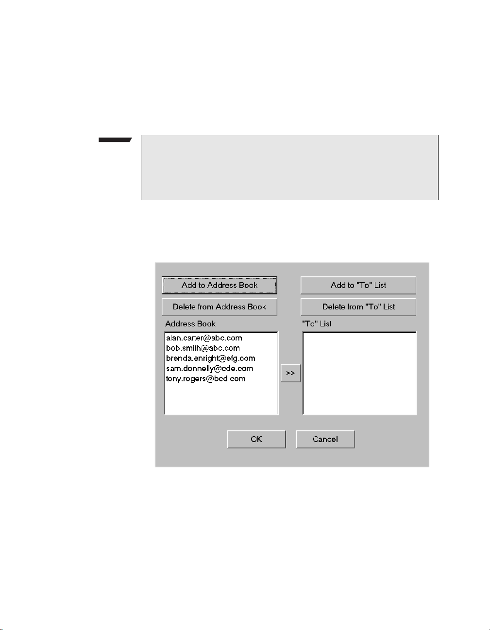
Chapter 2 Basic Operations
Sending e-mail
where internet provider name represents the name of the
company providing your internet service.
5 In From, type the address of an e-mail account you can retrieve
messages from.
NOTE:
You can not retrieve and read e-mail messages using the FST-2802
user interface; however, if you purchased the Networking and the
Web browser option, you can use the browser to access e-mail from
an ISP account.
6 In Subject, type the subject of the e-mail.
7 To specify the destination e-mail address, under To:, select Add.
The Address Maintenance dialog box appears.
If you added addresses to the Address Book previously, the
addresses appear in the Address Book.
64 FST-2802 TestPad User’s Guide Revision A
Page 91
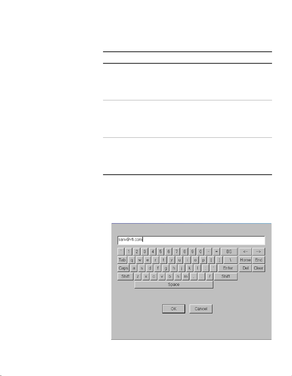
8 Do one of the following:
To… Do th i s …
Chapter 2 Basic Operations
Sending e-mail
Select an existing address from
the address book
Add a new address to the
address book
Add a new address without adding it to the address book
– Under Address Book, select
the address, and then select
>> to copy the address to the
“To” List.
– Proceed to step 10.
–Select Add to Address
Book. A keyboard dialog box
appears allowing you to type
the new address.
– Proceed to step 9.
–Select Add to “To” List. A
keyboard dialog box appears
allowing you to type the new
address.
– Proceed to step 9.
9 If you are adding an address, do the following:
a Type the address in the field provided. To type the “@” symbol,
select the Shift key.
The numeric keys change to symbol keys.
FST-2802 TestPad User’s Guide Revision A
65
Page 92
Chapter 2 Basic Operations
Launching Adobe Acrobat Reader
10 Select OK to return to the E-mail dialog box.
11 If you want to attach a file to the e-mail, do the following:
12 In Message, type the message to send with the e-mail, using up
13 Select Send.
The TestPad sends the e-mail to the address you specified.
b Select OK to return to the Address Maintenance dialog box.
The new address appears in the Address Book or “To” List.
The To: address is automatically populated.
a Under Attach, select Add.
The Select Attachment dialog box appears.
b Navigate to the file you want to attach, and then select the file.
c Select OK to return to the E-mail dialog box.
The file appears in the attached box.
to 100 characters.
Launching Adobe Acrobat Reader
The FST-2802 provides Adobe Acrobat Reader, which enables you to
read .PDF files on the TestPad.
To launch Adobe Acrobat Reader
– Select the Tools > Programs > PDFReader.
Acrobat Reader is launched.
NOTE:
To optimize performance of the TestPad, secondary features of
Acrobat Reader such as online help have been disabled.
66 FST-2802 TestPad User’s Guide Revision A
Page 93

Launching the VNC Viewer
If you purchased the Networking option, you can run remote applications from the TestPad using the VNC Viewer.
For example, if you have a laptop in your truck which is running a work
order application and a VNC server, and you are using the TestPad to
test a circuit, after you complete the test, you can close out the work
order from the TestPad without returning to your truck. To close the
work order, you do the following:
– Establish an 802.11b or Bluetooth connection from the TestPad to
the laptop.
– Launch the VNC Viewer on the TestPad.
– View the laptop’s work order application.
– Close the work order.
Before you launch the VNC Viewer, you must first establish a modem
dial-out, modem dial-in, or LAN connection to the network or laptop the
VNC server is running on.
Chapter 2 Basic Operations
Launching the VNC Viewer
To launch the VNC Viewer
1 Establish a modem dial-out, modem dial-in, or LAN connection
from the TestPad to the network or laptop the server is running on.
– For detailed instructions on establishing a modem dial-out
connection, see “Establishing modem dial-out connections” on
page 83.
– For detailed instructions on establishing a modem dial-in
connection, see “Establishing modem dial-in connections” on
page 85.
– For detailed instructions on establishing a LAN connection, see
“Establishing LAN connections” on page 87.
2 Connect a USB keyboard, or press the Keyboard key to launch
the on-screen keyboard.
3 Select Tools > Programs > VNC Viewer.
The Connection Details dialog box appears.
4 In VNC server, type the IP address or computer name of the
device running the server.
FST-2802 TestPad User’s Guide Revision A
67
Page 94
Chapter 2 Basic Operations
Launching the Web browser
5 If required, log into the server by typing a password.
The desktop for the device running the VNC server appears.
NOTE:
To optimize performance of the TestPad, secondary features of the
VNC Viewer such as online help have been disabled.
Launching the Web browser
If you purchased the Networking and Web browser options, you can
launch a Web browser from the FST-2802. You can use the Web
browser to view and retrieve intranet or Internet content (such as
methods and procedures or engineering records) and configure
network equipment.
Before you launch the Web browser, you must first establish a modem
dial-out or LAN connection to a network.
To launch the Web browser
1 Establish a modem dial-out or LAN connection.
– For detailed instructions on establishing a modem dial-out
connection, see “Establishing modem dial-out connections” on
page 83.
– For detailed instructions on establishing a LAN connection, see
“Establishing LAN connections” on page 87.
2 Connect a USB keyboard, or press the Keyboard key to launch
the on-screen keyboard.
3 Select Tools > Programs > Web browser.
The Internet Explorer browser appears.
4 Verify your browser connection by typing the address for the site
you want to access. If the browser displays the site, the connection is established.
NOTE:
To optimize performance of the TestPad, secondary features of the
Web browser such as online help have been disabled.
68 FST-2802 TestPad User’s Guide Revision A
Page 95
Emulating a VT100 terminal
If you purchased the VT100 option, the FST-2802 can emulate a
VT100 terminal. When you use the TestPad to emulate a VT100
terminal, the TestPad launches a HyperTerminal session. You can use
the session to retrieve performance information from network
elements and configure the elements.
Before starting VT100 emulation, you must first establish a serial
connection to the network element.
To emulate a VT100 terminal
1 Establish a serial connection. For detailed instructions on estab-
lishing a serial connection, see “Establishing serial connections”
on page 81.
2 Press the Keyboard key to launch the on-screen keyboard.
3 Select Tools > Programs > VT100.
The HyperTerminal session window appears.
Chapter 2 Basic Operations
Emulating a VT100 terminal
4 The menu for the network element appears after a few seconds.
Verify that you can retrieve information from the network element.
5 Use the menu selections to retrieve performance information or
configure the element.
6 Select File > Exit to end the HyperTerminal session.
NOTE:
To optimize performance of the TestPad, secondary HyperTerminal
features such as the ability to add a printer and online help have
been disabled.
Using the Remote GUI
If you purchased the Networking option, you can run the TestPad
remotely from any device with a Web browser using a VNC session.
You can use the Remote GUI to perform any of the tests available for
the FST-2802.
FST-2802 TestPad User’s Guide Revision A
69
Page 96

Chapter 2 Basic Operations
Using the Remote GUI
When you set up the TestPad, you should specify a Remote GUI password to restrict remote access to the TestPad. For detailed instructions, see “Specifying a Remote GUI password” on page 35.
Before you run the Remote GUI, the TestPad must be connected to the
network your PC or laptop is connected to via a modem dial-in, modem
dial-out, or LAN connection, or locally via a USB connection. You also
need the IP address or computer name of the TestPad.
Determining the
TestPad’s IP
address or
computer name
Running the
Remote GUI
To determine the TestPad’s IP address or computer name
1 On the TestPad, select Tools > Connectivity.
The Connectivity Menu appears.
2 Select the Network Info tab.
The TestPad’s IP address and computer name appear.
To run the Remote GUI
1 Establish a network connection to the TestPad.
– For detailed instructions on establishing a modem dial-out
connection, see “Establishing modem dial-out connections” on
page 83.
– For detailed instructions on establishing a modem dial-in
connection, see “Establishing modem dial-in connections” on
page 85.
– For detailed instructions on establishing a LAN connection, see
“Establishing LAN connections” on page 87.
2 From the laptop or PC, launch a Web browser.
3 Type the following address:
http://ip address:5800
Where ip address is the IP address of the TestPad.
A dialog box appears prompting you to enter the Remote GUI
password.
4 Type the Remote GUI password, and then select OK.
The Remote GUI for the TestPad appears on your screen.
70 FST-2802 TestPad User’s Guide Revision A
Page 97
Chapter 2 Basic Operations
Managing files
5 Verify the connection for the Remote GUI by doing the following:
– Using the Remote GUI, change the default configuration for the
Te st P ad .
– Verify the configuration settings in the configuration summary
bar of the Remote GUI.
6 To use the Remote GUI:
– Use your mouse to select the elements on the GUI that you
would typically “tap” on the TestPad. For example, if you want
to select the Setup button to configure a test, using your
mouse, simply click the Setup button on the Remote GUI.
– To access the Extended Keys for the TestPad, select the Tools
button at the bottom right corner of the main screen to display
the Tools menu, and then select the command that corresponds to the Extended key on the TestPad.
You are running the Remote GUI.
NOTE:
If you are running the RFC 2544 script from a Remote GUI session,
you must use the Windows Task Manager to run the script. See
“Running the script from a Remote GUI session” on page 169 for
detailed instructions.
Managing files
Selecting files
You can view, run, delete, rename, copy, and paste files (for example,
print files and test scripts) on the TestPad from the File Management
dialog box. For example, you can rename print files, copy print files to
a PCMCIA card, or delete print files. If you establish a network connection, you can also transfer files to and from local drives and FTP
servers.
Before you view, run, rename, copy, or delete a file, you must first
select the file.
To select a file
1 Select Tools > File Management.
FST-2802 TestPad User’s Guide Revision A
71
Page 98
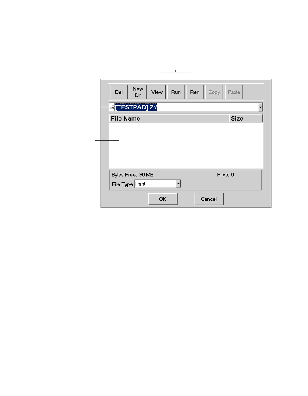
Chapter 2 Basic Operations
Managing files
Current drive/
folder
File selection
box
The File Management dialog box appears with the local drive for
the TestPad displayed as the current drive.
Button bar
2 To navigate to the file, select the Current Drive/Folder drop-down
arrow.
72 FST-2802 TestPad User’s Guide Revision A
Page 99
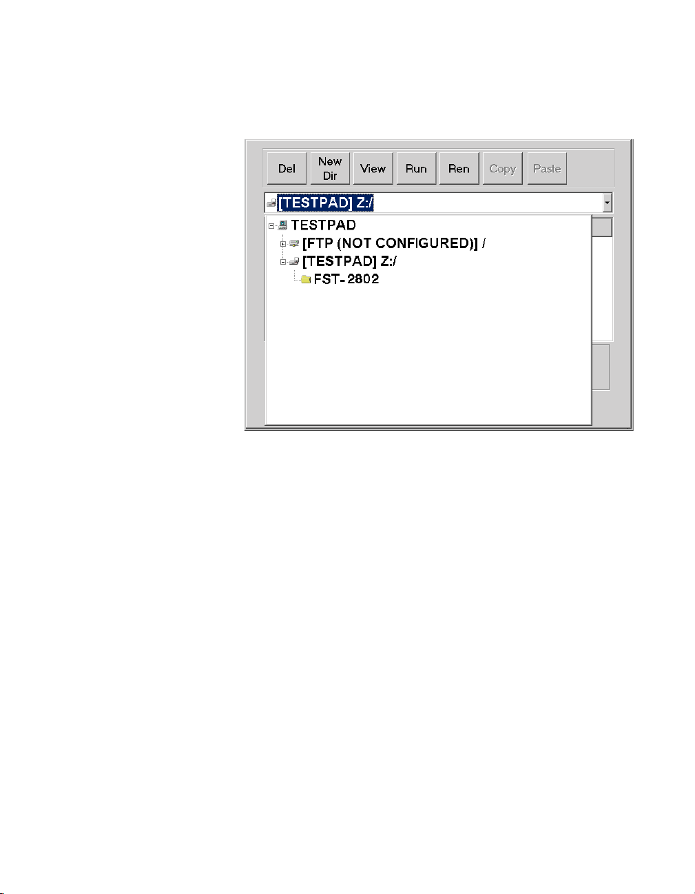
Chapter 2 Basic Operations
Managing files
A drop-down list of drives and folders appears under the current
drive/folder.
3 Do the following:
a Select + to expand a drive or folder.
b Tap or click the folder to select the folder with the file.
c Tap or click the Current Drive/Folder drop-down arrow to select
the drive and folder and close the drop-down list.
FST-2802 TestPad User’s Guide Revision A
73
Page 100
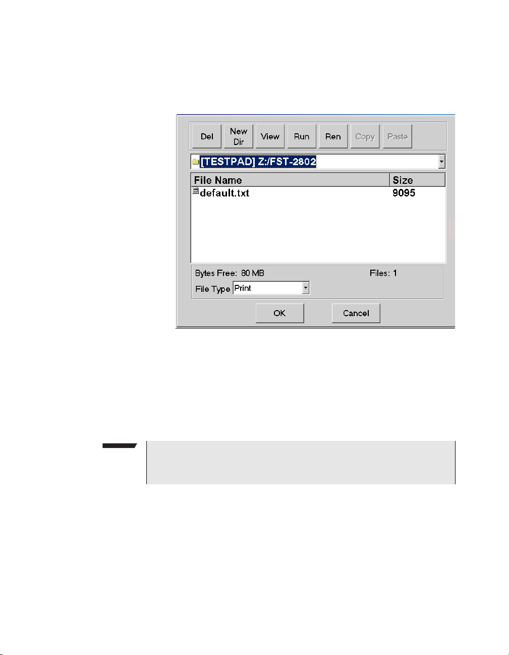
Chapter 2 Basic Operations
Managing files
The drop-down list of drives and folders disappears, the
selected folder appears in the Current Drive/Folder field, and
the files in the folder appear in the File Selection box.
4 Select a file from the File Selection box.
The file is selected.
Filtering files
You can filter the files in the File Selection box to display only specific
types of files, such as print files or test scripts.
NOTE:
The print files you generate and store on the TestPad are stored as
text (.txt) files.
To filter the displayed files
– Select the File Type drop-down arrow, and then select Print,
Scripts or All.
74 FST-2802 TestPad User’s Guide Revision A
 Loading...