

Page 1

Installation and Operation Manual
Phone: 800.894.0412 - Fax: 208.368.0415 - www.ctiautomation.net - e.mail: info@ctiautomation.net
QC Series
Page 2

1.0 GENERAL
Phone: 800.894.0412 - Fax: 208.368.0415 - www.ctiautomation.net - e.mail: info@ctiautomation.net
1.1 PRODUCTS COVERED IN THIS MANUAL
This manual covers the AC Tech QC1000, QC2000, and QC3000 Variable Frequency Drives.
1.2 PRODUCT CHANGES
AC Technology Corporation reserves the right to discontinue or make modifications to the design of its
products and manuals without prior notice, and holds no obligation to make modifications to products sold
previously. AC Technology Corporation also holds no liability for losses of any kind which may result
from this action. Instruction manuals with the most up-to-date information are available for download
from the AC Tech website (www.actechdrives.com).
1.3 WARRANTY
AC Technology Corporation warrants the QC Series AC motor control to be free of defects in material and
workmanship for a period of eighteen months from the date of sale to the user, or two years from the date
of shipment, which ever occurs first. Any control component, which under normal use, becomes defective,
within the stated warranty time period, shall be returned to AC Technology Corporation, freight prepaid,
for examination. AC Technology Corporation reserves the right to make the final determination as to the
validity of a warranty claim, and sole obligation is to repair or replace only components which have been
rendered defective due to faulty material or workmanship. No warranty claim will be accepted for
components which have been damaged due to mishandling, improper installation, unauthorized repair
and/or alteration of the product, operation in excess of design specifications or other misuse, or
improper maintenance. AC Technology Corporation makes no warranty that its products are compatible
with any other equipment, or to any specific application, to which they may be applied and shall not be
held liable for any other consequential damage or injury arising from the use of its products.
This warranty is in lieu of all other warranties, expressed or implied. No other person, firm or
corporation is authorized to assume, for AC Technology Corporation, any other liability in
connection with the demonstration or sale of its products.
1.4 RECEIVING
Inspect all cartons for damage which may have occurred during shipping. Carefully unpack equipment and
inspect thoroughly for damage or shortage. Report any damage to carrier and/or shortages to supplier. All
major components and connections should be examined for damage and tightness, with special attention
given to PC boards, plugs, knobs and switches.
1.5 CUSTOMER MODIFICATION
AC Technology Corporation, its sales representatives and distributors, welcome the opportunity to assist
our customers in applying our products. Many customizing options are available to aid in this function.
AC Technology Corporation cannot assume responsibility for any modifications not authorized by its
engineering department.
1
Page 3

2.0 QC SERIES SPECIFICATIONS
Phone: 800.894.0412 - Fax: 208.368.0415 - www.ctiautomation.net - e.mail: info@ctiautomation.net
Storage Temperature -20° to 70° C
Ambient Operating Temperature Chassis: -10 to 50° C (40° C for QC3000)
(with 8 kHz or lower carrier, Type 1 Enclosed -10 to 50° C (40° C for QC3000)
derate for higher carriers) Type 4 / 12 Enclosed -10 to 40° C
Ambient Humidity Less than 95% (non-condensing)
Altitude 3300 feet (1000 meters) above sea level without derating
Input Line Voltages 200/240 Vac, 400/480 Vac, and 480/590 Vac
Input Voltage Tolerance +10%, -15%
Input Frequency Tolerance 48 to 62 Hz
Output Wave Form Sine Coded PWM
Output Frequency 0-120 Hz Standard, 0 - 650 Hz Optional
Type 12 Enclosed -10 to 40° C
Type 4X Enclosed -10 to 40° C
Carrier Frequency 1.5, 8, 10, or 12 kHz
Frequency Stability + 0.00006% / °C
Efficiency 97% or better
Power Factor (displacement) 0.96 or better
Service Factor 1.00
Overload Current Capacity 150 % for one minute (QC1000/2000)
(based on drive output current rating) 120 % for one minute (QC3000)
Speed Reference Follower 0-10 VDC, or 4-20 mA
Control Voltage 24 VDC
Analog Outputs 0-10 VDC, 2-10 VDC, 4-20 mA
Proportional to speed or load
12 VDC Pulse Train (40-50% Duty Cycle)
Proportional to speed
Digital Outputs Form C relays: 2A at 24 VDC or 120 Vac
Open-collector output: 40 mA at 30 VDC
2
Page 4

3.0 QC SERIES MODEL DESIGNATION CODE
Phone: 800.894.0412 - Fax: 208.368.0415 - www.ctiautomation.net - e.mail: info@ctiautomation.net
The model number of a QC Series drive gives a full description of the basic drive unit (see example
below).
EXAMPLE:
Q14005HB
(QC1000, 480 Vac, 5 HP, Type 1 Enclosure with extended enclosure)
Q1 4 005 H B - XXX
Series:
Q1 = QC1000 Series - Constant Torque - NEMA 1 and Chassis
Q2 = QC2000 Series - Constant Torque - NEMA 4 / 12 & 4X
Q3 = QC3000 Series - Variable Torque - NEMA 1 and Chassis
Input Voltage:
2 = 240/200Vac (For 208 and 240 Vac; 50 or 60 Hz)
4 = 480/400Vac (For 380, 415, 440, 460 and 480 Vac; 50 or 60 Hz)
5 = 590/480Vac (For 440, 460, 480, 575 and 600 Vac; 50 or 60 Hz)
Horsepower:
001 = 1 Hp
002 = 2 Hp
003 = 3 Hp
005 = 5 Hp
008 = 7½ Hp
010 = 10 Hp
Extended Enclosures:
H = Extended enclosure.
No character indicates standard height enclosure.
Required for line reactor option. Line reactors are standard on 240 Vac models from 25 to
60 Hp, 480 Vac models from 25 to 250 Hp, and 590 Vac from 5 to 200 Hp.
Enclosure Type:
A = Chassis - Open Frame
B = NEMA 1 - General Purpose, vented: Indoor
C = NEMA 4 - Washdown: Indoor / Outdoor (NEMA 4 rating exceeds NEMA 12 rating)
D = NEMA 12 - Dust-tight and Drip-tight: Indoor
E = NEMA 4X - Washdown, Stainless steel: Indoor / Outdoor
Special Designation:
Non-standard special models have a three digit suffix.
015 = 15 Hp
020 = 20 Hp
025 = 25 Hp
030 = 30 Hp
040 = 40 Hp
050 = 50 Hp
060 = 60 Hp
075 = 75Hp
100 = 100Hp
125 = 125Hp
150 = 150 Hp
200 = 200 Hp
250 = 250 Hp
3
Page 5
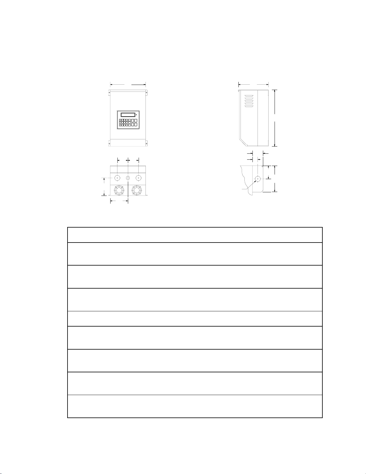
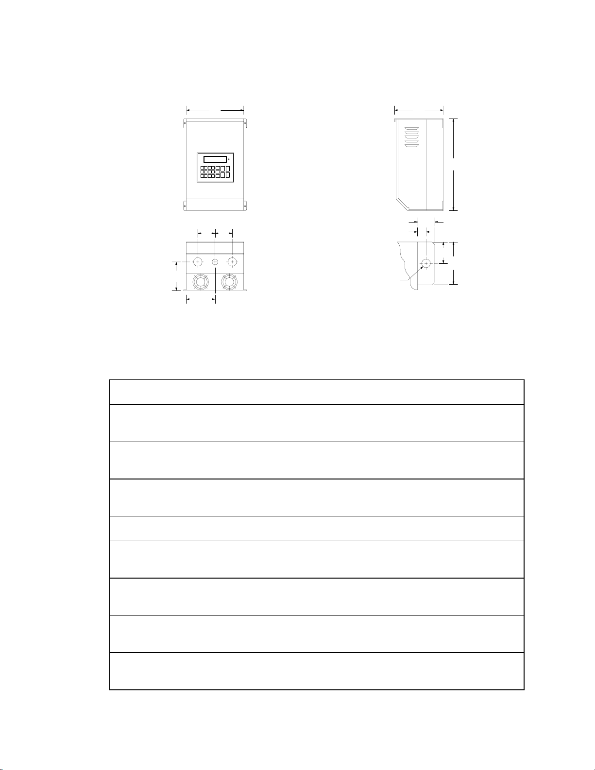
4.0 QC SERIES DIMENSIONS
Phone: 800.894.0412 - Fax: 208.368.0415 - www.ctiautomation.net - e.mail: info@ctiautomation.net
4.1 QC1000 - CHASSIS AND TYPE 1 ENCLOSED
W
Q
Q
P
N
INPUT
HP VOLTAGE MODEL H W D N P Q R T U V
1 240 / 200 Q12001 12.00 7.44 5.91 3.72 2.75 2.12 1.00 0.28 0.37 0.68
480 / 400 Q14001 12.00 7.44 5.91 3.72 2.75 2.12 1.00 0.28 0.37 0.68
590 / 480 Q15001 12.00 7.44 5.91 3.72 2.75 2.12 1.00 0.28 0.37 0.68
2 240 / 200 Q12002 12.00 7.44 7.91 3.72 4.75 2.12 1.00 0.28 0.37 0.68
480 / 400 Q14002 12.00 7.44 7.91 3.72 4.75 2.12 1.00 0.28 0.37 0.68
590 / 480 Q15002 12.00 7.44 7.91 3.72 4.75 2.12 1.00 0.28 0.37 0.68
3 240 / 200 Q12003 12.00 7.44 7.91 3.72 4.75 2.12 1.00 0.28 0.37 0.68
480 / 400 Q14003 12.00 7.44 7.91 3.72 4.75 2.12 1.00 0.28 0.37 0.68
590 / 480 Q15003 12.00 7.44 7.91 3.72 4.75 2.12 1.00 0.28 0.37 0.68
5 480 / 400 Q14005 12.00 7.44 7.91 3.72 4.75 2.12 1.00 0.28 0.37 0.68
590 / 480 Q15005 15.50 7.44 7.91 3.72 4.75 2.12 1.00 0.28 0.37 0.68
7.5 240 / 200 Q12008 14.00 8.88 9.50 4.44 5.75 2.50 1.00 0.28 0.37 0.68
480 / 400 Q14008 12.00 7.44 7.91 3.72 4.75 2.12 1.00 0.28 0.37 0.68
590 / 480 Q15008 15.50 7.44 7.91 3.72 4.75 2.12 1.00 0.28 0.37 0.68
10 240 / 200 Q12010 14.00 8.88 9.50 4.44 5.75 2.50 1.00 0.28 0.37 0.68
480 / 400 Q14010 14.00 8.88 9.50 4.44 5.75 2.50 1.00 0.28 0.37 0.68
590 / 480 Q15010 19.00 8.88 9.84 4.44 6.13 2.50 1.00 0.28 0.37 0.68
15 240 / 200 Q12015 14.00 8.88 9.50 4.44 5.75 2.50 1.00 0.28 0.37 0.68
480 / 400 Q14015 14.00 8.88 9.50 4.44 5.75 2.50 1.00 0.28 0.37 0.68
590 / 480 Q15015 19.00 8.88 9.84 4.44 6.13 2.50 1.00 0.28 0.37 0.68
20 240 / 200 Q12020 19.00 8.88 9.84 4.44 6.13 2.50 1.00 0.28 0.37 0.68
480 / 400 Q14020 19.00 8.88 9.84 4.44 6.13 2.50 1.00 0.28 0.37 0.68
590 / 480 Q15020 25.00 8.88 10.50 4.44 6.50 2.50 1.50 0.36 0.37 0.68
Conduit Holes:
If Q = 2.12", all = 1.13" dia.
If Q = 2.50", middle = 1.13" dia.
left & right = 1.38" dia.
D
V
U
T
Dia.
Mounting Tab Detail
H
R
2R
4
Page 6
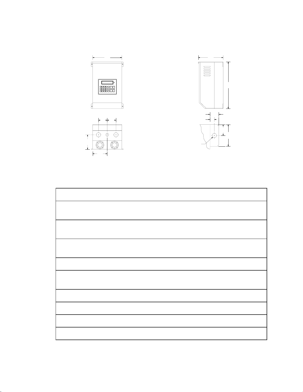
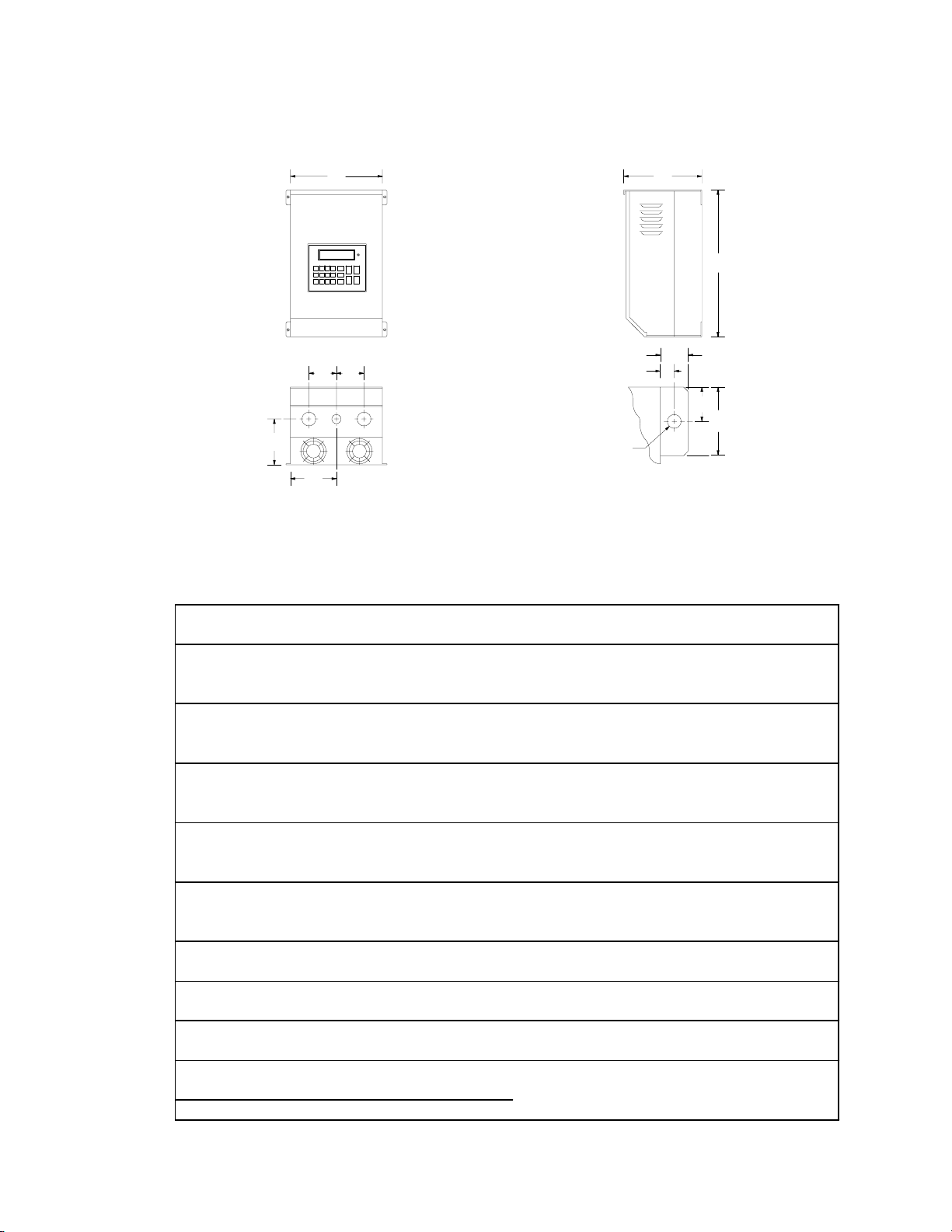
4.1 QC1000 - CHASSIS AND TYPE 1 ENCLOSED
Phone: 800.894.0412 - Fax: 208.368.0415 - www.ctiautomation.net - e.mail: info@ctiautomation.net
W
Q
Q
P
N
INPUT
HPVOLTAGEMODELHWDNPQRTUV
25 240 / 200 Q12025 25.00 8.88 10.50 4.44 6.50 2.50 1.50 0.36 0.37 0.68
480 / 400 Q14025 25.00 8.88 10.50 4.44 6.50 2.50 1.50 0.36 0.37 0.68
590 / 480 Q15025 25.00 8.88 10.50 4.44 6.50 2.50 1.50 0.36 0.37 0.68
30 240 / 200 Q12030 25.00 8.88 10.50 5.56 6.50 2.50 1.50 0.36 0.37 0.68
480 / 400 Q14030 25.00 8.88 10.50 4.44 6.50 2.50 1.50 0.36 0.37 0.68
590 / 480 Q15030 25.00 8.88 10.50 4.44 6.50 2.50 1.50 0.36 0.37 0.68
40 240 / 200 Q12040 25.00 13.00 10.50 5.56 6.50 2.62 1.50 0.36 0.37 0.68
480 / 400 Q14040 25.00 13.00 10.50 5.56 6.50 2.62 1.50 0.36 0.37 0.68
590 / 480 Q15040 25.00 13.00 10.50 5.56 6.50 2.62 1.50 0.36 0.37 0.68
50 480 / 400 Q14050 25.00 13.00 10.50 5.56 6.50 2.62 1.50 0.36 0.37 0.68
590 / 480 Q15050 25.00 13.00 10.50 5.56 6.50 2.62 1.50 0.36 0.37 0.68
60 240 / 200 Q12060 29.00 16.64 11.85 7.14 6.88 3.12 1.50 0.44 0.49 0.92
480 / 400 Q14060 29.00 16.64 11.85 7.14 6.88 3.12 1.50 0.44 0.49 0.92
590 / 480 Q15060 29.00 16.64 11.85 7.14 6.88 3.12 1.50 0.44 0.49 0.92
75 480 / 400 Q14075 29.00 16.64 11.85 7.14 6.88 3.12 1.50 0.44 0.49 0.92
590 / 480 Q15075 29.00 16.64 11.85 7.14 6.88 3.12 1.50 0.44 0.49 0.92
100 480 / 400 Q14100 29.00 24.42 11.85 11.12 6.50 4.50 1.50 0.44 0.49 0.92
590 / 480 Q15100 29.00 24.42 11.85 11.12 6.50 4.50 1.50 0.44 0.49 0.92
125 480 / 400 Q14125 29.00 24.42 11.85 11.12 6.50 4.50 1.50 0.44 0.49 0.92
590 / 480 Q15125 29.00 24.42 11.85 11.12 6.50 4.50 1.50 0.44 0.49 0.92
150 480 / 400 Q14150 29.00 36.66 11.85
590 / 480 Q15150 29.00 36.66 11.85
Conduit Holes:
If Q = 2.50", middle = 1.13" dia.
left & right = 1.38" dia.
If Q = 2.62", left = 1.13" dia.
middle & right = 1.38" dia.
If Q = 3.12", left = 1.13" dia.
middle & right = 1.75" dia.
If Q = 4.50", left = 1.13" dia.
middle & right = 2.50" dia.
SEE SECTION 4.7 - PAGE 11
D
V
U
T
Dia.
Mounting Tab Detail
H
R
2R
5
Page 7
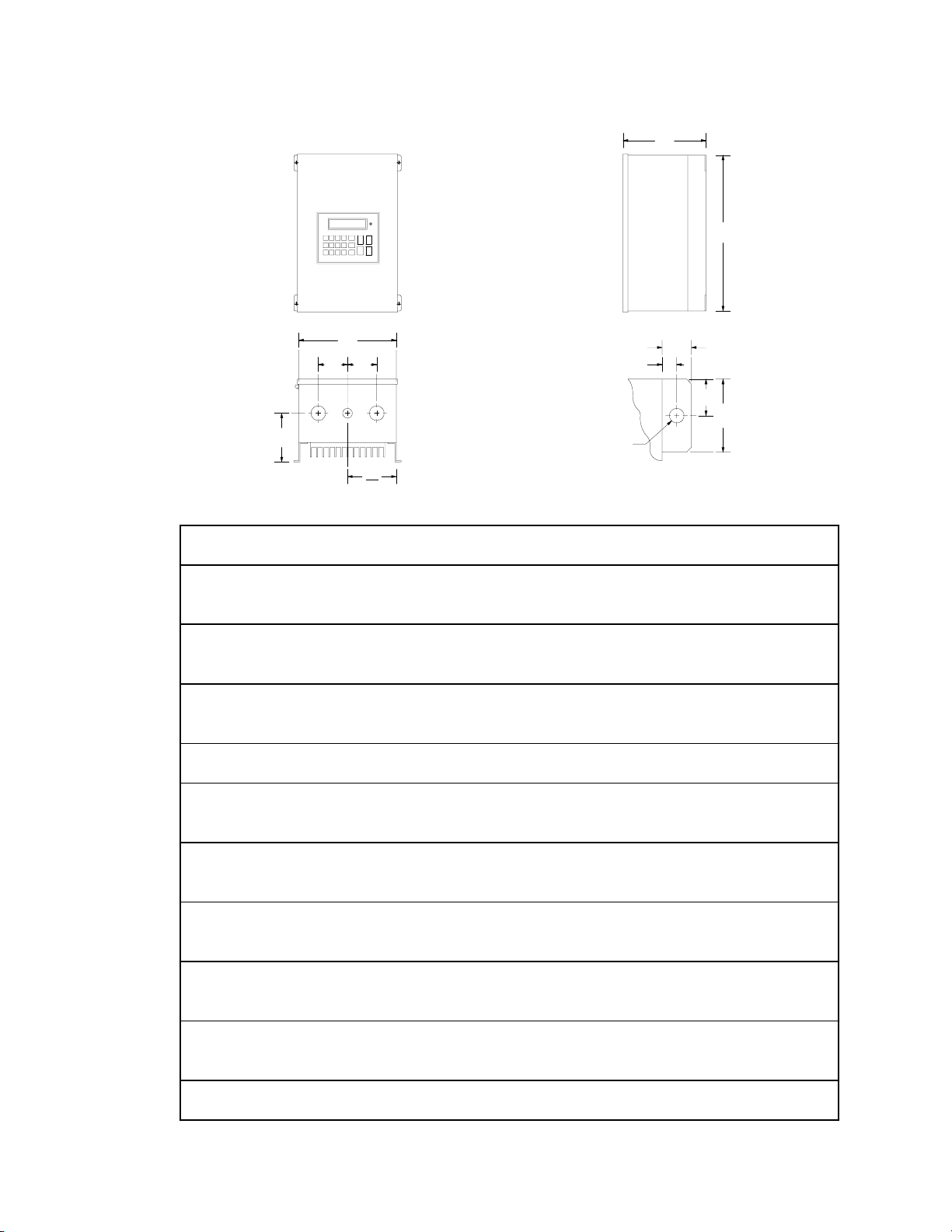
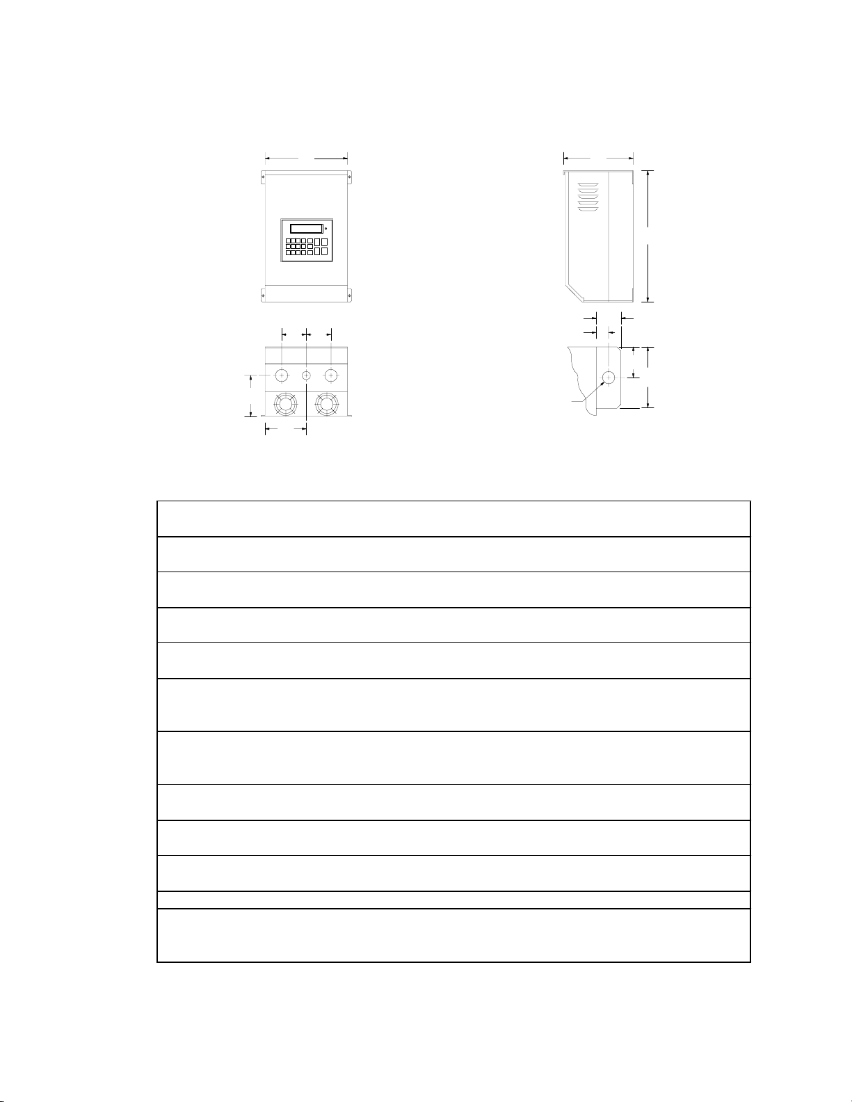
4.2 QC2000 - TYPE 4/12 AND 4X ENCLOSED
Phone: 800.894.0412 - Fax: 208.368.0415 - www.ctiautomation.net - e.mail: info@ctiautomation.net
D
H
W
QQ
Conduit Holes:
If Q = 2.12", all = 1.13" dia.
P
If Q = 2.50", middle = 1.13" dia.
left & right = 1.38" dia.
W
2
T
Dia.
V
U
R
2R
Mounting Tab Detail
INPUT
HP VOLTAGE MODEL H W D P Q R T U V
1 240 / 200 Q22001 13.00 7.88 6.19 3. 50 2.12 1.00 0.28 0.37 0.68
480 / 400 Q24001 13.00 7. 88 6.19 3.50 2. 12 1.00 0. 28 0.37 0.68
590 / 480 Q25001 13.00 7. 88 6.19 3.50 2. 12 1.00 0. 28 0.37 0.68
2 240 / 200 Q22002 13.00 7.88 7.25 4. 56 2.12 1.00 0.28 0.37 0.68
480 / 400 Q24002 13.00 7. 88 6.19 3.50 2. 12 1.00 0. 28 0.37 0.68
590 / 480 Q25002 13.00 7. 88 6.19 3.50 2. 12 1.00 0. 28 0.37 0.68
3 240 / 200 Q22003 13.00 7.88 7.25 4. 56 2.12 1.00 0.28 0.37 0.68
480 / 400 Q24003 13.00 7. 88 7.25 4.56 2. 12 1.00 0. 28 0.37 0.68
590 / 480 Q25003 13.00 7. 88 7.25 4.56 2. 12 1.00 0. 28 0.37 0.68
5 480 / 400 Q24005 16.00 9.70 7.50 4. 81 2.12 1.00 0.28 0.37 0.68
590 / 480 Q25005 16.00 9. 70 7.50 4.81 2. 12 1.00 0. 28 0.37 0.68
7.5 240 / 200 Q22008 19.00 11.38 8. 83 5.63 2.50 1. 00 0.28 0. 37 0.68
480 / 400 Q24008 16.00 9. 70 7.50 4.81 2. 12 1.00 0. 28 0.37 0.68
590 / 480 Q25008 16.00 9. 70 7.50 4.81 2. 12 1.00 0. 28 0.37 0.68
10 240 / 200 Q22010 19.00 11.38 8.83 5. 63 2.50 1.00 0.28 0.37 0.68
480 / 400 Q24010 19.00 11.38 8.83 5.63 2.50 1. 00 0.28 0.37 0.68
590 / 480 Q25010 19.00 11.38 8.83 5.63 2.50 1. 00 0.28 0.37 0.68
15 240 / 200 Q22015 19.00 11.38 8.83 5. 63 2.50 1.00 0.28 0.37 0.68
480 / 400 Q24015 19.00 11.38 8.83 5.63 2.50 1. 00 0.28 0.37 0.68
590 / 480 Q25015 19.00 11.38 8.83 5.63 2.50 1. 00 0.28 0.37 0.68
20 240 / 200 Q22020 29.00 11.74 9.78 5. 88 2.50 1.50 0.36 0.37 0.68
480 / 400 Q24020 29.00 11.74 9.78 5.88 2.50 1. 50 0.36 0.37 0.68
590 / 480 Q25020 29.00 11.74 9.78 5.88 2.50 1. 50 0.36 0.37 0.68
25 240 / 200 Q22025 29.00 11.74 10.98 7.08 2.50 1. 50 0.36 0.37 0. 68
480 / 400 Q24025 29.00 11.74 9.78 5.88 2.50 1. 50 0.36 0.37 0.68
590 / 480 Q25025 29.00 11.74 9.78 5.88 2.50 1. 50 0.36 0.37 0.68
30 480 / 400 Q24030 29.00 11.74 10.98 7.08 2.50 1. 50 0.36 0.37 0. 68
590 / 480 Q25030 29.00 11.74 10.98 7.08 2.50 1. 50 0.36 0. 37 0.68
Page 8
4.3 QC2000 - TYPE 12 ENCLOSED
Phone: 800.894.0412 - Fax: 208.368.0415 - www.ctiautomation.net - e.mail: info@ctiautomation.net
D
AIR FLOWAIR FLOW
If H = 31.00"
Y = 22.50"
Y
If H > 37.00"
Y = 27.00"
W
QQ
P
N
Conduit Holes:
If Q = 2.62", left = 1.13" dia.
middle & right = 1.38" dia.
If Q = 3.13", left = 1.13" dia.
middle & right = 1.75" dia.
If Q = 4.50", left = 1.13" dia.
middle & right = 2.50" dia.
T
Dia.
Mounting Tab Detail
U
H
V
2R
R
INPUT
HPVOLTAGEMODELHWDNPQRTUV
30 240 / 200 Q22030 31.00 14.00 11.86 6.00 7.50 2.62 1.50 0.36 0.37 0.68
40 240 / 200 Q22040 31.00 14.00 11.86 6.00 7.50 2.62 1.50 0.36 0.37 0.68
480 / 400 Q24040 31.00 14.00 11.86 6.00 7.50 2.62 1.50 0.36 0.37 0.68
590 / 480 Q25040 31.00 14.00 11.86 6.00 7.50 2.62 1.50 0.36 0.37 0.68
50 480 / 400 Q24050 31.00 14.00 11.86 6.00 7.50 2.62 1.50 0.36 0.37 0.68
590 / 480 Q25050 31.00 14.00 11.86 6.00 7.50 2.62 1.50 0.36 0.37 0.68
60 240 / 200 Q22060 37.00 18.00 13.30 7.50 8.00 3.13 1.50 0.49 0.50 0.92
480 / 400 Q24060 37.00 18.00 13.30 7.50 8.00 3.13 1.50 0.49 0.50 0.92
590 / 480 Q25060 37.00 18.00 13.30 7.50 8.00 3.13 1.50 0.49 0.50 0.92
75 480 / 400 Q24075 37.00 18.00 13.30 7.50 8.00 3.13 1.50 0.49 0.50 0.92
590 / 480 Q25075 37.00 18.00 13.30 7.50 8.00 3.13 1.50 0.49 0.50 0.92
100 480 / 400 Q24100 39.00 26.00 13.30 11.50 8.00 4.50 1.50 0.49 0.50 0.92
590 / 480 Q25100 39.00 26.00 13.30 11.50 8.00 4.50 1.50 0.49 0.50 0.92
125 480 / 400 Q24125 39.00 26.00 13.30 11.50 8.00 4.50 1.50 0.49 0.50 0.92
590 / 480 Q25125 39.00 26.00 13.30 11.50 8.00 4.50 1.50 0.49 0.50 0.92
7
Page 9
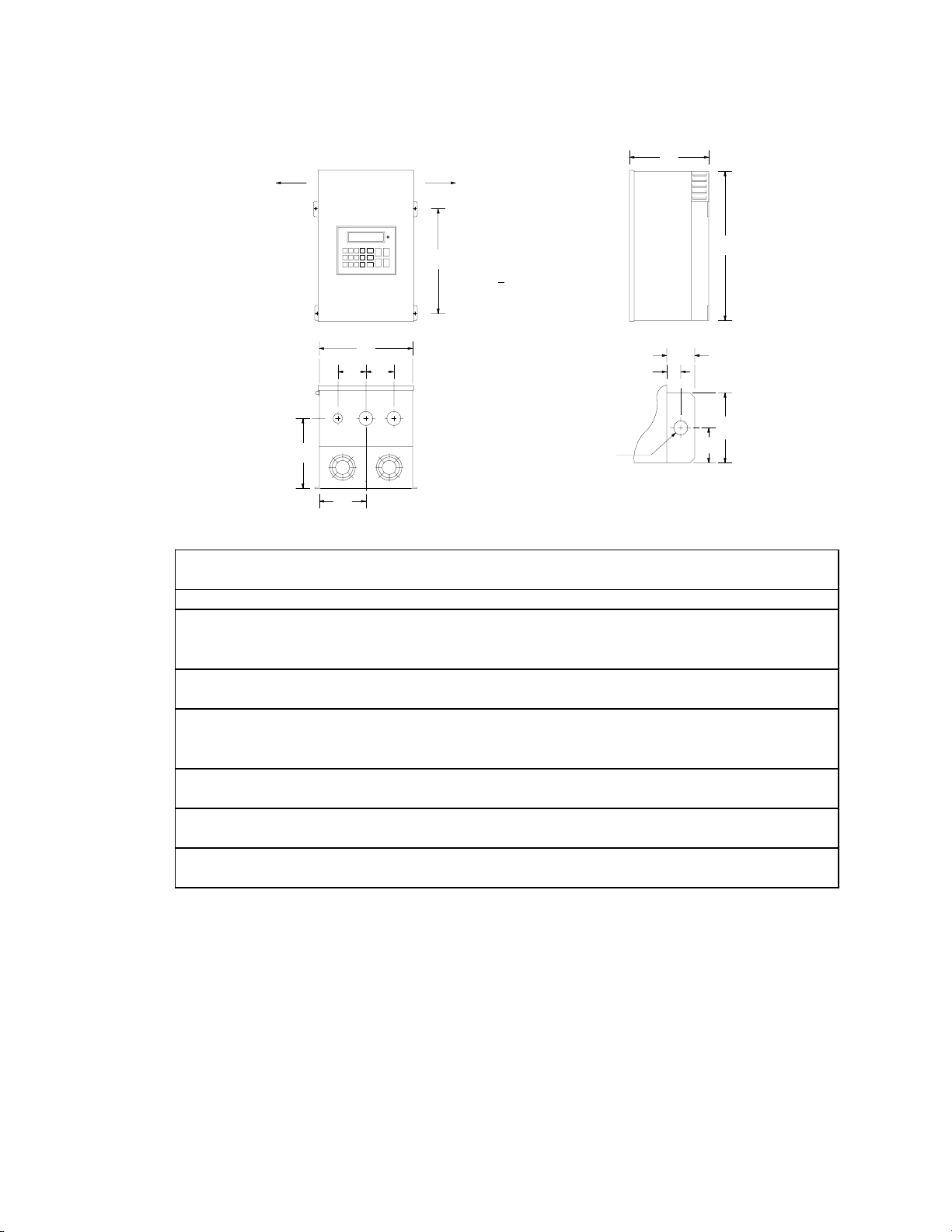
4.4 QC3000 - CHASSIS AND TYPE 1 ENCLOSED
Phone: 800.894.0412 - Fax: 208.368.0415 - www.ctiautomation.net - e.mail: info@ctiautomation.net
W
Q
Q
P
N
INPUT
HP VOLTAGE MODEL H W D N P Q R T U V
2 240 / 200 Q32002 12. 00 7.44 7.91 3.72 4.75 2.12 1.00 0.28 0.37 0.68
480 / 400 Q34002 12.00 7.44 7.91 3.72 4.75 2.12 1.00 0.28 0.37 0.68
590 / 480 Q35002 12.00 7.44 7.91 3.72 4.75 2.12 1.00 0.28 0.37 0.68
3 240 / 200 Q32003 12. 00 7.44 7.91 3.72 4.75 2.12 1.00 0.28 0.37 0.68
480 / 400 Q34003 12.00 7.44 7.91 3.72 4.75 2.12 1.00 0.28 0.37 0.68
590 / 480 Q35003 12.00 7.44 7.91 3.72 4.75 2.12 1.00 0.28 0.37 0.68
5 240 / 200 Q32005 12. 00 7.44 7.91 3.72 4.75 2.12 1.00 0.28 0.37 0.68
480 / 400 Q34005 12.00 7.44 7.91 3.72 4.75 2.12 1.00 0.28 0.37 0.68
590 / 480 Q35005 15.50 7.44 7.91 3.72 4.75 2.12 1.00 0.28 0.37 0.68
7.5 480 / 400 Q34008 12. 00 7.44 7.91 3.72 4.75 2.12 1.00 0.28 0.37 0.68
590 / 480 Q35008 15.50 7.44 7.91 3.72 4.75 2.12 1.00 0.28 0.37 0.68
10 240 / 200 Q32010 14.00 8.88 9.50 4.44 5.75 2.50 1.00 0.28 0.37 0.68
480 / 400 Q34010 12.00 7.44 7.91 3.72 4.75 2.12 1.00 0.28 0.37 0.68
590 / 480 Q35010 15.50 7.44 7.91 3.72 4.75 2.12 1.00 0.28 0.37 0.68
15 240 / 200 Q32015 14.00 8.88 9.50 4.44 5.75 2.50 1.00 0.28 0.37 0.68
480 / 400 Q34015 14.00 8.88 9.50 4.44 5.75 2.50 1.00 0.28 0.37 0.68
590 / 480 Q35015 19.00 8.88 9.84 4.44 6.13 2.50 1.00 0.28 0.37 0.68
20 240 / 200 Q32020 19.00 8.88 9.84 4.44 6.13 2.50 1.00 0.28 0.37 0.68
480 / 400 Q34020 19.00 8.88 9.84 4.44 6.13 2.50 1.00 0.28 0.37 0.68
590 / 480 Q35020 25.00 8.88 10.50 4.44 6.50 2.50 1.50 0.36 0.37 0.68
25 240 / 200 Q32025 25.00 8.88 10.5 4.44 6.50 2.50 1.50 0.36 0.37 0.68
480 / 400 Q34025 25.00 8.88 10.5 4.44 6.50 2.50 1.50 0.36 0.37 0.68
590 / 480 Q35025 25.00 8.88 10.5 4.44 6.50 2.50 1.50 0.36 0.37 0.68
Conduit Holes:
If Q = 2.12", all = 1.13" dia.
If Q = 2.50", middle = 1.13" dia.
left & right = 1.38" dia.
D
V
U
R
T
Dia.
Mounting Tab Detail
H
2R
8
Page 10
4.4 QC3000 - CHASSIS AND TYPE 1 ENCLOSED
Phone: 800.894.0412 - Fax: 208.368.0415 - www.ctiautomation.net - e.mail: info@ctiautomation.net
W
Q
Q
P
N
INPUT
HPVOLTAGEMODELHWDNPQRTUV
30 240 / 200 Q32030 25.00 8.88 10.50 4.44 6.50 2.50 1.50 0.36 0.37 0.68
480 / 400 Q34030 25.00 8.88 10.50 4.44 6.50 2.50 1.50 0.36 0.37 0.68
590 / 480 Q35030 25.00 8.88 10.50 4.44 6.50 2.50 1.50 0.36 0.37 0.68
40 240 / 200 Q32040 25.00 13.00 10.50 5.56 6.50 2.62 1.50 0.36 0.37 0.68
480 / 400 Q34040 25.00 13.00 10.50 5.56 6.50 2.62 1.50 0.36 0.37 0.68
590 / 480 Q35040 25.00 8.88 10.50 5.56 6.50 2.62 1.50 0.36 0.37 0.68
50 240 / 200 Q32050 25.00 13.00 10.50 5.56 6.50 2.62 1.50 0.36 0.37 0.68
480 / 400 Q34050 25.00 13.00 10.50 5.56 6.50 2.62 1.50 0.36 0.37 0.68
590 / 480 Q35050 25.00 13.00 10.50 5.56 6.50 2.62 1.50 0.36 0.37 0.68
60 240 / 200 Q32060 47.00 16.64 11.85 7.14 6.88 3.12 1.50 0.44 0.49 0.92
480 / 400 Q34060 25.00 13.00 10.50 5.56 6.50 2.62 1.50 0.36 0.37 0.92
590 / 480 Q35060 25.00 13.00 10.50 5.56 6.50 2.62 1.50 0.36 0.37 0.92
75 240 / 200 Q32075 47.00 16.64 11.85 7.14 6.88 3.12 1.50 0.44 0.49 0.92
480 / 400 Q34075 29.00 16.64 11.85 7.14 6.88 3.12 1.50 0.44 0.49 0.92
590 / 480 Q35075 29.00 16.64 11.85 7.14 6.88 3.12 1.50 0.44 0.49 0.92
100 480 / 400 Q34100 29.00 16.64 11.85 7.14 6.88 3.12 1.50 0.44 0.49 0.92
590 / 480 Q35100 29.00 16.64 11.85 7.14 6.88 3.12 1.50 0.44 0.49 0.92
125 480 / 400 Q34125 29.00 24.42 11.85 11.12 6.50 4.50 1.50 0.44 0.49 0.92
590 / 480 Q35125 29.00 24.42 11.85 11.12 6.50 4.50 1.50 0.44 0.49 0.92
150 480 / 400 Q34150 29.00 24.42 11.85 11.12 6.50 4.50 1.50 0.44 0.49 0.92
590 / 480 Q35150 29.00 24.42 11.85 11.12 6.50 4.50 1.50 0.44 0.49 0.92
200 480 / 400 Q34200 29.00 36.66 11.85
590 / 480 Q35200 29.00 36.66 11.85
250 480 / 400 Q34250 29.00 36.66 11.85
Conduit Holes:
If Q = 2.50", middle = 1.13" dia.
left & right = 1.38" dia.
If Q = 2.62", left = 1.13" dia.
middle & right = 1.38" dia.
If Q = 3.12", left = 1.13" dia.
middle & right = 1.38" dia.
If Q = 4.50", left = 1.13" dia.
middle & right = 2.50" dia.
SEE SECTION 4.7 - PAGE 11
D
V
U
R
T
Dia.
Mounting Tab Detail
H
2R
Page 11
4.5 QC1000 AND QC3000 - CHASSIS AND TYPE 1 EXTENDED
Phone: 800.894.0412 - Fax: 208.368.0415 - www.ctiautomation.net - e.mail: info@ctiautomation.net
W
Q
Q
P
N
INPUT
HP VOLTAGE MODEL H W D N P Q R T U V
1 240 / 200 Q12001H 15.50 7.44 7.91 3.72 4.75 2.12 1.00 0.28 0.37 0.68
480 / 400 Q14001H 15. 50 7.44 7.91 3.72 4.75 2.12 1.00 0.28 0.37 0.68
2 240 / 200 Q* 2002H 15.50 7.44 7.91 3.72 4.75 2.12 1.00 0.28 0.37 0.68
480 / 400 Q*4002H 15.50 7.44 7.91 3.72 4.75 2.12 1.00 0.28 0.37 0.68
3 240 / 200 Q* 2003H 15.50 7.44 7.91 3.72 4.75 2.12 1.00 0.28 0.37 0.68
480 / 400 Q*4003H 15.50 7.44 7.91 3.72 4.75 2.12 1.00 0.28 0.37 0.68
5 240 / 200 Q32005H 15.50 7.44 7.91 3.72 4.75 2.12 1.00 0.28 0.37 0.68
480 / 400 Q*4005H 15.50 7.44 7.91 3.72 4.75 2.12 1.00 0.28 0.37 0.68
7.5 240 / 200 Q12008H 19.00 8.88 9.84 4.44 6.13 2.50 1.00 0.28 0.37 0.68
480 / 400 Q14008H 15. 50 7.44 7.91 3.72 4.75 2.12 1.00 0.28 0.37 0.68
Q34008H 15.50 7.44 7.91 3.72 4.75 2.12 1.00 0.28 0.37 0.68
10 240 / 200 Q*2010H 19.00 8.88 9.84 4.44 6.13 2.50 1.00 0.28 0.37 0.68
480 / 400 Q14010H 19. 00 8.88 9.84 4.44 6.13 2.50 1.00 0.28 0.37 0.68
Q34010H 15.50 7.44 7.91 3.72 4.75 2.12 1.00 0.28 0.37 0.68
15 240 / 200 Q*2015H 19.00 8.88 9.84 4.44 6.13 2.50 1.00 0.28 0.37 0.68
480 / 400 Q*4015H 19.00 8.88 9.84 4.44 6.13 2.50 1.00 0.28 0.37 0.68
20 240 / 200 Q*2020H 25.00 8.88 10. 50 4.44 6.50 2.50 1.50 0.36 0.37 0.68
480 / 400 Q*4020H 25.00 8.88 10.50 4.44 6.50 2.50 1.50 0.36 0.37 0.68
25 240 / 200 Q*2025H 25.00 13.00 10. 50 5.56 6.50 2.50 1.50 0.36 0.37 0.68
480 / 400 Q*4025H 25.00 13.00 10.50 5.56 6.50 2.50 1.50 0.36 0.37 0.68
30 480 / 400 Q*4030H 25.00 13.00 10. 50 5.56 6.50 2.50 1.50 0.36 0.37 0.68
Conduit Holes:
If Q = 2.12", all = 1.13" dia.
If Q = 2.50", middle = 1.13" dia.
left & right = 1.38" dia.
D
V
U
T
Dia.
Mounting Tab Detail
H
R
2R
NOTE: * = 1 or 3, depending on model. See Section 3.0 for model number breakdown.
10
Page 12
4.6 QC2000 - TYPE 4/12 AND 4X EXTENDED
Phone: 800.894.0412 - Fax: 208.368.0415 - www.ctiautomation.net - e.mail: info@ctiautomation.net
D
H
W
QQ
Conduit Holes:
If Q = 2.12", all = 1.13" dia.
P
W
If Q = 2.50", middle = 1.13"
left & right = 1.38"
2
T
Dia.
Mounting Tab Detail
V
U
R
2R
INPUT
HP VOLTAGE MODEL H W D P Q R T U V
1 240 / 200 Q22001H 16.00 9.70 7.50 4.81 2.12 1.00 0.28 0.37 0.68
480 / 400 Q24001H 16.00 9.70 7.50 4.81 2.12 1.00 0.28 0.37 0.68
2 240 / 200 Q22002H 16.00 9.70 7.50 4.81 2.12 1.00 0.28 0.37 0.68
480 / 400 Q24002H 16.00 9.70 7.50 4.81 2.12 1.00 0.28 0.37 0.68
3 240 / 200 Q22003H 16.00 9.70 7.50 4.81 2.12 1.00 0.28 0.37 0.68
480 / 400 Q24003H 16.00 9.70 7.50 4.81 2.12 1.00 0.28 0.37 0.68
4.7 MOUNTING TAB AND CONDUIT HOLE DIMENSIONS
The following diagram applies to 150 HP QC1000, 200 HP QC3000, and 250 HP QC3000 models only.
V
U
N
7.25"
Conduit Holes: Large holes = 3.00"
Small holes = 1.13"
Q
P
P
6.50"
T
Dia.
Mounting Tab Detail
1.36"
3.00"
1.36"
11
N = 7.45"
P = 9.00"
Q = 7.00"
T = 0.44"
U = 0.49"
V = 0.92"
Page 13

5.0 QC SERIES RATINGS
Phone: 800.894.0412 - Fax: 208.368.0415 - www.ctiautomation.net - e.mail: info@ctiautomation.net
MODEL
MODEL CURRENT NOMINA L
NUMBER RATED INPUT (AMPS) POWER CURRENT POWER
(NOT E 1)
Q*2001 1 3 4.6 1.9 4.0 1.6
Q*2001S 1 1 / 3 8.5 / 4.6 2.0 / 1.9 4.0 1.6
Q*2002 2 3 8.1 3.4 6.8 2.7
Q*2002S 2 1 / 3 14.9 / 8.1 3.6 / 3.4 6.8 2.7
Q*2003 3 3 11.3 4.7 9.6 3.8
Q*2003S 3 1 / 3 21.0 / 11.3 5. 0 / 4. 7 9.6 3.8
Q32005 5 3 17.7 7.3 15.2 6.1
HP PHASE
Q1200 , Q2200, AN D Q3200 SERIES RATING S
INPUT OUTPUT
(240 Vac, 50 - 60 Hz) (0 - 230 Vac)
NOMINA L
(NOT E 2)
(KVA) (AMPS) (KVA)
Q12008 / Q22008 7.5 3 25.0 10.5 22.0 8.8
Q*2010 10 3 32.0 13.2 28.0 11.2
Q*2015 15 3 47.6 19.8 42.0 16.7
Q*2020 20 3 61.0 25.3 54.0 21.5
Q*2025 25 3 64.0 26.6 68.0 27.1
Q*2030 30 3 76.0 31.6 80.0 31.9
Q*2040 40 3 99.0 41.0 104.0 41.4
Q32050 50 3 122.0 50.7 130.0 51.8
Q*2060 60 3 145.0 60.5 154. 0 61.3
Q*2075 75 3 182.0 75.7 192. 0 76.5
NOTE 1: See Secti on 3.0 for m odel num b er breakdow n ( * = 1, 2, or 3, depending on m odel ) .
NOTE 2: For 200 Vac input voltage on T H REE PHASE,
Q1200 AND Q2200
MODELS ONLY, mu lti pl y the input and output
curr en t ratin gs by 1.2 an d the output v ol tage by 0. 8 3.
For
thr ee pha s e models, m ult i ply the inp ut and output powe r, and output v olt a ge, by 0.83.
Q3200
Q3200 models may hav e to be oversized t o me et the c ur re nt requi r em e nts of 200 Vac appli cations.
NOTE 3 : See Sec ti on 8 .0 for rec ommended fuse type.
12
Page 14

Q1400 , Q2400, AND Q3400 SERI E S R A T INGS
Phone: 800.894.0412 - Fax: 208.368.0415 - www.ctiautomation.net - e.mail: info@ctiautomation.net
INPUT
INPUT O UTPUT
INPUTINPUT
MODEL
MODEL (480 Vac, 50 - 60 Hz) (0 - 460 Vac)
MODELMODEL
NOMINAL
MODEL CURRENT NOMINAL
NUMBER RATED INPUT (AMPS) POWER CURRENT POWER
(NOT E 1)
Q*4001 1 3 2.3 1.9 2.0 1.6
Q*4002 2 3 4.0 3.4 3.4 2.7
Q*4003 3 3 5.7 4.7 4.8 3.8
Q*4005 5 3 8.8 7.3 7.6 6.1
Q*4008 7.5 3 12.6 10.5 11.0 8.8
Q*4010 10 3 15.9 13.2 14.0 11.2
Q*4015 15 3 24 19.8 21 16.7
Q*4020 20 3 31 25.4 27 21.5
Q*4025 25 3 32 26.7 34 27.1
HP PHASE
(NOT E 2)
(KVA) (AMPS) (KVA)
OUTPUT
OUTPUTOUTPUT
Q*4030 30 3 38 31.5 40 31.9
Q*4040 40 3 49 41.0 52 41.4
Q*4050 50 3 61 50.7 65 51.8
Q*4060 60 3 73 60.5 77 61.3
Q*4075 75 3 91 75.5 96 76.5
Q*4100 100 3 116 96.4 124 98.8
Q*4125 125 3 146 121.4 156 124.3
Q*4150 150 3 168 139.7 180 143.4
Q34200 200 3 225 187.1 240 191.2
Q34250 250 3 281 233.6 302 240.6
NOTE 1: See Secti on 3.0 for m ode l num ber br eakdow n ( * = 1, 2, or 3 , dependi ng on m odel).
NOTE 2: For 400 Vac inp ut v ol tage on Q14 00 A N D Q240 0
Q14 00 AND Q2400 MODELS ONLY, m ul tip l y t he input and output c ur r ent ra tings
Q1400 AND Q2400 Q1400 AND Q2400
by 1.2 a nd the output voltage b y 0.83.
For Q3400
Q34 00 m od els, mul ti pl y the input and ou tput pow er , and output v ol tage, by 0.83.
Q3400 Q3400
Q3400 models may hav e to be oversized to meet the curre nt requi r em e nts of 400 Vac appli cation s .
NOTE 3 : See Sec ti on 8.0 for recommended fuse type.
13
Page 15

Q1500 , Q2500, AND Q3500 SERI E S R A T INGS
Phone: 800.894.0412 - Fax: 208.368.0415 - www.ctiautomation.net - e.mail: info@ctiautomation.net
INPUT
INPUT O UTPUT
INPUTINPUT
MODEL
MODEL (590 Vac, 50 - 60 Hz) (0 - 575 Vac)
MODELMODEL
NOMINAL
MODEL CURRENT NOMINAL
NUMBER RATED INPUT (AMPS) POWER CURRENT POWER
(NOT E 1)
Q*5001 1 3 1.8 1.9 1.6 1.6
Q*5002 2 3 3.3 3.4 2.7 2.7
Q*5003 3 3 4.6 4.7 3.9 3.9
Q*5005 5 3 5.8 5.9 6.1 6.1
Q*5008 7.5 3 8.6 8.8 9.0 8.9
Q*5010 10 3 10.6 10.9 11.0 11.0
Q*5015 15 3 16.4 16.7 17.0 16.9
Q*5020 20 3 21 21.3 22 21.5
Q*5025 25 3 26 26.9 27 26.9
HP PHASE
(NOT E 2)
(KVA) (AMPS) (KVA)
OUTPUT
OUTPUTOUTPUT
Q*5030 30 3 31 31.6 32 31.9
Q*5040 40 3 40 40.5 41 40.9
Q*5050 50 3 50 51.1 52 51.8
Q*5060 60 3 60 60.9 62 61.7
Q*5075 75 3 74 75.7 77 76.7
Q*5100 100 3 95 96.6 99 98.6
Q*5125 125 3 119 121.6 125 124.5
Q*5150 150 3 137 140.0 144 143.4
Q35200 200 3 183 187.0 192 191.2
NOTE 1: See Secti on 3.0 for m ode l num ber br eakdow n ( * = 1, 2, or 3 , dependi ng on m odel).
NOTE 2: For 480 Vac inp ut v ol tage on Q15 00 A N D Q250 0
Q15 00 AND Q2500 MODELS ONLY, m ul tiply the in put and outputc ur r ent ra tings
Q1500 AND Q2500Q1500 AND Q2500
by 1.23 and the output v ol tage by 0.81.
For Q3500
Q35 00 m od els, mul ti pl y the input and ou tput pow er , and t h e output v olt age, by 0.81.
Q3500 Q3500
Q3500 models may hav e to be oversized to meet the curre nt requi r em e nts of 480 Vac appli cation s .
NOTE 3 : See Sec ti on 8.0 for recommended fuse type.
14
Page 16

6.0 THEORY
Phone: 800.894.0412 - Fax: 208.368.0415 - www.ctiautomation.net - e.mail: info@ctiautomation.net
6.1 DESCRIPTION OF AC MOT OR OPERATION
Three phase AC motors are comprised of two major components, the stator and th e rotor. The stator is a
set of three electrical windings held stationar y in the motor housing. The rotor is a metal cylinder, fixed
to the motor drive shaft, which rotates within the stator. The ar rangemen t of the stator coils and the
presence of three phase AC voltage give rise to a rotating magnetic field which drives the rotor. The
speed at which the magnetic field rotates is known as the synchronous speed of the motor. Syn chronous
speed is a function of th e fr equency at which the voltage is alternating and the number of poles in the
stator windings.
The following equation gives the relation between synchronous speed, frequency, and the number of
poles:
Ss = 120 f/p
Wher e: Ss = Syn chr onous speed (rpm ), f = frequency (Hz), p = nu mber of poles
In three phase induction motors the actual shaft speed differs from the synchronous speed as load is
applied. This difference is known as "slip". Slip is commonly expressed as a percentage of synchronous
speed. A typical value is three percent at full load.
The strength of the magnetic field in the gap between the r otor and stator is proportional to the amplitude
of the voltage at a given frequency. The output torque capability of the motor is, therefore, a function of
the applied voltage amplitude at a given frequency. When operated below base (rated) speed, AC motors
run in the range of "constant torque". Constant torque output is obtain ed by maintaining a constant ratio
between voltage amplitude (volts) and frequency (Hz). For 60 Hz, 230, 460, and 575 volt motors,
common values for this V/Hz ratio are 3.83, 7.66, and 9.58 respectively. Operating with these V/Hz
ratios gen erally yield optimum torque capability. Operating at lower ratios decreases tor que an d power
capability. Operating at higher ratios will cause the motor to overheat. Most standard motors are capable
of providing full torque output from 3 to 60 Hz. However , at lower speeds, where motor coolin g fan s
becom e less effective, supplemental cooling may be n eeded to operate at full torque output continuously.
If the fr equency applied to the motor is increased while the voltage remains constant, torque capability
will decrease as speed increases. This will cause the horsepower capability of the motor to remain
app roxi mate ly const ant . Motor s ru n in thi s mode wh en op erat ed above ba se speed , wher e dr ive out put
voltage is limited by the in put line voltage. This operating range is known as the "constant horsepower"
range. The typical maximum range for constant horsepower is about 2.3 to 1 (60 to 140 Hz). The
diagram below depicts the operating characteristics of a typical AC induction motor .
WARNING!
Con s ult mot or m an ufacturer befor e op e ra ting motor and/or dr iven e qui pment above r ate d spee d.
15
Page 17
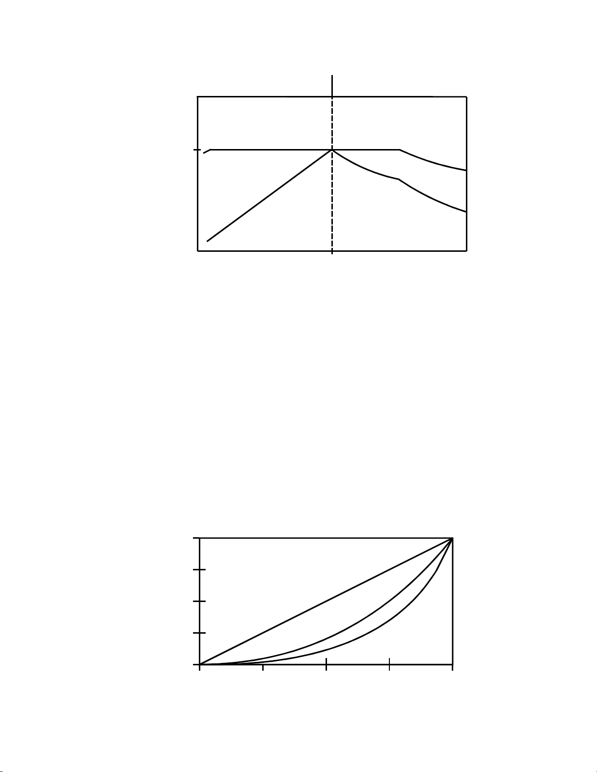
CONSTANT TORQUE
Phone: 800.894.0412 - Fax: 208.368.0415 - www.ctiautomation.net - e.mail: info@ctiautomation.net
CONSTANT HP
100
TORQUE HORSEPOWER
TORQUE (%)
HORSEPOWER
BASE FREQUENCY (%)
6.1.1 CONSTANT T ORQUE VS. VARIABLE TORQUE
Variable frequency dri ves, an d the loads they a re applied to, can generally be divided into two groups:
constant torque and variable torque. Constant torque loads include: vibrating conveyors, punch presses,
rock crushers, machine tools, and just about every other application that is not considered variable torque.
Variable torque loads include centrifugal pumps and fans, which make up the majority of HVAC
applications.
The term constant torque is not entirely accurate in terms of the torque required for an application.
Many constant torque applications have reciprocating loads, such as vibrating conveyors and punch
presses, wh ere the rotation al motion of the motor is being converted to a lin ear motion. In such cases, the
torque required can vary greatly at different poin ts in the cycle. For constant torque loads, this flucuation
in torque is not a dir ect function of speed, as it is with a variable torque load.
TORQUE
100
Variable torque loads are governed by the affinity laws, which define the relationships between speed,
flow, torque and horsepower. The diagram below illustrates these relation ships:
100%
75%
50%
% FLOW
25%
0%
0%
25% 5 0% 75% 100%
% TORQUE
% HORSEPOWER
SPEED (%)
16
Page 18

Variable torque refers to th e fact that the torque requir ed varies with the square of the speed. Also, the
Phone: 800.894.0412 - Fax: 208.368.0415 - www.ctiautomation.net - e.mail: info@ctiautomation.net
horsepower required varies with the cube of the speed, resulting in a large reduction in horsepower for
even a small reduction in speed. It is easily seen that substantial energy savings can be achieved by
reducing the speed of a fan or pump. For example, reducing the speed to 50% results in a 50 HP motor
having to produce only 12.5% of rated horsepower, or 6.25 HP.
There are two major differences between a constant torque drive and a variable torque drive. One is that a
constant torque drive generally has a higher overload capacity rating. Constant torque loads have higher
peak torque demands, which require the ability to handle higher currents. Variable torque loads rarely
experience full load, and therefore usually have a lower overload capacity. The other difference is that
constant torque drives follow a constant V/Hz ratio to achieve maximum torque, while variable torque
drives follow a variable V/Hz ratio to optimize efficiency and energy savings.
6.2 DRIVE FUNCTION DESCRIPTION
The QC Series is a 16 bit microprocessor based, keypad programmable, variable speed AC motor drive.
There are four major sections; an input diode bridge and DC bus filter, a power board, a control board, and
an output intelligent power module.
6.2.1 DRIVE OPERATION
Incoming AC line voltage is converted to a pulsating DC voltage by the input diode bridge. The DC
voltage is supplied to the bus filter capacitors through a charge circuit which limits inrush current to the
capacitors during power-u p. The pulsating DC voltage is filter ed by the bus capacitors which re duces the
ripple level. The filtered DC voltage enters the inverter section of the drive, composed of six output
intelligent insulated gate bi-polar transistors (IGBT’s) which make up the three output legs of the drive.
Each leg has one intelligent IGBT connected to the positive bus voltage and one connected to the negative
bus voltage. Alternately switching on each leg, the intelligent IGBT produces an alternating voltage on
each of the corresponding motor windings. By switching each output intelligent IGBT at a very high
frequency (known as the carrier frequency) for varying time intervals, the inverter is able to produce a
smooth, three phase, sinusoidal output current wave which optimizes motor performance.
6.2.2 CIRCUIT DESCRIPTION
The control section consists of a control board with a 16 bit microprocessor, keypad and display. Drive
programming is accomplished via the keypad or the serial communications port. During operation the
drive can be controlled via the keypad, by control devices wired to the control terminal strip, or by the
serial communications port. The Power Board contains the control and protection circuits which govern
the six output IGBT’s. The Power Board also co ntains a charging circuit f or the bus filter capacitors, a
motor current feedback circuit, a voltage feedback circuit, and a fault signal circuit. The drive has several
built in protection circuits. These include phase-to-phase and phase-to-ground short circuit protection,
high and low line voltage protection, protection against excessive ambient temperature, and protection
against continuous excessive output current. Activation of any of these circuits will cause the drive to shut
down in a fault condition.
17
Page 19

6.2.3 QC ANALOG INPUT SIGNALS
Phone: 800.894.0412 - Fax: 208.368.0415 - www.ctiautomation.net - e.mail: info@ctiautomation.net
The QC Series drive allows for three speed reference input signals: speed potentiometer (10,000 Ohm), 420 mA, or 0-10 VDC. For control by a speed pot., th e wiper lead is connected to terminal TB-5A, and the
hig h an d low end l eads ar e connected to termi nals TB-6 an d TB-2, r espectivel y. For 4-20 mA con trol,
wire the positive to terminal TB-5B and the negative to terminal TB-2. For 0-10 VDC control, wire the
positive to terminal TB-5D and the negative to terminal TB-2. See the control wir ing diagram in Section
15.0.
The input im pedance of termina l TB-5A (speed pot input) is 100 kilohms, TB-5B (4-20 m A input) is
100 ohms, and TB-5D (0-10 VDC input) is 200 kil ohm s. T erm i nal TB-2 is circuit common.
The control voltage of the microprocessor control board is 24 VDC, (Isolated, referenced to circuit
common - terminal TB-2).
6.2.4 QC ANALOG OUTPUT SIGNALS
There are four terminals that can supply a nalog output signals proportional to output frequency or load.
Terminal TB-10B can provide a 0-10 VDC signal proportiona l to frequency or load. Termi nal TB-10C
provides a 12 VDC pulse train proportional to frequency with a 40-50% duty cycle. Term inal TB-10D
can provide a 4-20 mA signal pr oportional to frequency or load, and termin al TB-10E can provide a 0-10
VDC or 2-10 VDC sign al proportional t o frequency or l oad. The 2-10 VDC signal can be converted to a
4-20 mA signal usin g a resistor in ser ies with the signal such that t he total circuit resistan ce is 500 ohm.
See Parameters: 50 - TB10B/D FUNCTION, and 53 - TB10E FUNCTION in Section 18.0 DESCRIPTION OF PARAMETERS.
6.2.5 QC ST AT US OUTPUT RELAYS
The control board has two FORM C relays at terminals TB-16, 17, 18, and TB-19, 20, 21. TB-16 and
TB-19 are normally open contacts, and TB-18 and TB-21 are normally closed contacts. TB-17 and TB-20
are common. Contacts are ra ted 2 amps at 28 VDC or 120 Vac.
Ther e i s a l so one op en -col lect or out put a t t er m inal T B-1 4. T h e open -col lect or cir cu it is a cur ren t- si n ki n g
type rated at 30 VDC and 40 mA maximum.
The FORM C relays and the open-collector output can be pr ogrammed to indicate any of the following:
NO FUNCTION, RUN, FAULT, FAULT LOCKOUT, AT SPEED, ABOVE SET SPEED, CURRENT
LIMIT, FOLLOWER PRESENT, MAINTENANCE TARGET, AUTO SPEED MODE, or START
PENDING. See Parameters: 121 - RELAY #1 FUNCTION, 122 - RELAY #2 FUNCTION, and 124 - TB14 FUNCTION, in Section 18.0 - DESCRIPTION OF PARAMETERS.
The following describes the functionality of the possible relay output settings:
NO FUNCTION This setting disables the relay output.
RUN The relay energizes when the drive is given a START command, and remains
energized until: a STOP command is given and the output frequency has
deceler ated to 0. 5 Hz, th e dri ve has "t ri pped", or th e in put volt age is removed.
Note that this relay indicates only that the drive is in the RUN mode. It does
not necessarily indicate that the motor is turnin g.
18
Page 20

FAULT The relay energizes when input voltage is applied to the drive and remains
Phone: 800.894.0412 - Fax: 208.368.0415 - www.ctiautomation.net - e.mail: info@ctiautomation.net
energized until the drive “trips” into a fault condition, or input voltage is
removed.
FAULT LOCKOUT This relay can be used when the drive is programmed to automatically restart
after a fault. The relay energizes when input voltage is applied to the drive and
remains energized until the drive has faulted and unsuccessfully attempted the
number of restarts programmed in Parameter 72 - RESTART LIMIT, or input
voltage is removed.
AT SPEED The relay energizes when the drive reaches the commanded frequency. To avoid
a “chattering” relay (constantly energizing and de-energizing) due to small
fluctuations in speed, the relay will change states only when the speed has
changed by +
ABOVE SET SPD ABOVE SET SPEED - The relay energizes when the output frequency of the
drive exceeds the value in Parameter 123 – REL. SET SPD, and de-energizes
when the output frequency is equal to or less than REL. SET SPD.
CURRENT LIMIT The relay energizes when the drive is operating in current limit. Once the current
limit relay is energized, it remains energized for a minimum of 500ms, regardless
of whether the drive is still in current limit. At the end of the 500ms interval, the
relay will de-energize if the drive is no longer in current limit. See Parameter 1 CURRENT in Section 18.0 - DESCRIPTION OF PARAMETERS.
FOLLOWER PRES FOLLOWER PRESENT - The relay energizes when the 4-20 mA speed
reference input signal (TB-5B) is greater than 2 mA, and de-energizes when the
signal falls below 2 mA.
MAINT. TARGET MAINTENANCE TARGET - The relay energizes after the time period
programmed in Parameter 132 - MAINTENANCE TARGET has elapsed. The
relay will de-energize when a new time is programmed into Parameter 132.
AUTO SPEED MODE The relay energizes when the drive is in the AUTOMATIC MODE, and de-
energizes in the MANUAL MODE. This function is active only if Parameter 67
- AUTO/MANUAL SELECT is set to AUTO/MANUAL SPEED or
AUTO/MANUAL LOCAL. The relay will remain energized if Parameter 67 is
set to AUTO SPEED. This function will not be active if Parameter 67 is set to
MANUAL SPEED.
START PENDING The relay will energize if the drive has faulted, and is programmed for automatic
restart after a fault. START PENDING will appear on the keypad display when
the drive is in this condition. The relay will de-energize after the delay
programmed into Parameter 73 - RESTART DELAY, at which time the drive
will attempt to restart.
3 Hz.
19
Page 21

7.0 INSTALLATION
Phone: 800.894.0412 - Fax: 208.368.0415 - www.ctiautomation.net - e.mail: info@ctiautomation.net
DRIVES MUST NOT BE INSTALLED WHERE SUBJECTED TO ADVERSE ENVIRONMENTAL
CONDITIONS! DRIVES MUST NOT BE INSTALLED WHERE SUBJECTED TO: COMBUSTIBLE,
OILY, OR HAZARDOUS VAPORS OR DUST; EXCESSIVE MOISTURE OR DIRT; STRONG
VIBRATION; EXCESSIVE AMBIENT TEMPERATURES. CONSULT AC TECHNOLOGY FOR
MORE INFORMATION ON THE SUITABILITY OF A DRIVE TO A PARTICULAR ENVIRONMENT.
The drive should be mounted on a smooth vertical surface capable of safely supporting the unit without
vibrating. The LCD display has an optimum field of view, this should be considered when determining the
mounting position.
Chassis models must be installed in an electrical enclosure which will provide complete mechanical
protection and maintain uniform internal temperature within the drive’s ambient operating temperature
rating. All drive models MUST be mounted in a vertical position for proper heatsink cooling.
Maintain a minimum spacing around the drive of 4 inches for units rated 20 HP and below, 6 inches for
units rated 25-50 HP, and 8 inches for units rated 60 HP and above.
Fans or blowers should be used to insure proper cooling in tight quarters. Do not mount drives above other
drives or heat producing equipment that would impede the cooling of the drive. Note the ambient
operating temperature ratings for each drive model.
WARNING!
If it is necessary to drill or cu t the drive en closure or p anel, extreme care must be take n to avoid da maging
drive components or contaminating the drive with metal fragments (which cause shorting of electrical
circuits). Cover drive components with a clean cloth to keep out metal chips and other debris. Use a
vacuum cleaner to clean drive components after drilling, even if chips do not appear to be present. Do not
attempt to use positive air pressure to blow chips out of drive, as this tends to lodge debris under electronic
components. Contaminating the drive with metal chips can cause drive failure and will void the warranty.
7.1 INSTALLATION AFTER A LONG PERIOD OF STORAGE
WARNING!
Severe damage to the drive can result if it is operated after a long period of storage or inactivity without
reforming the DC bus capacitors!
If input power has not been applied to the drive for a period of time exceeding one year (due to storage,
etc), the electrolytic DC bus capacitors within the drive can change internally, resulting in excessive
leakage current. This can result in premature failure of the capacitors if the drive is operated after such a
long period of inactivity or storage.
In order to reform the capacitors and prepare the drive for operation after a long period of inactivity, apply
input power to the drive for 2 hours prior to actually operating the drive/motor system.
20
Page 22

7.2 EXPLOSION PROOF APPLICATIONS
Phone: 800.894.0412 - Fax: 208.368.0415 - www.ctiautomation.net - e.mail: info@ctiautomation.net
Explosion proof motors that are not rated for inverter use lose their certification when used for variable
speed. Due to the many areas of liability that may be encountered when dealing with these applications,
the following statement of policy applies:
"AC Technology Corporation inverter products are sold with no warranty of fitness for a particular
purpose or warranty of suitability for use with explosion proof motors. AC Technology Corporation
accepts no responsibility for any direct, or incidenta l or consequential loss, co st, or dama ge tha t may
arise through the use of its AC inverter products in these applications. The purchaser expressly
agrees to assume all risk of any loss, cost, or damage that may arise from such application. AC
Technology Corporation or AC Technology Corporation’s engineering department will not
knowingly approve applicati ons involving explosion proof mot ors."
21
Page 23

8.0 INPUT AC POWER REQUIREMENTS
Phone: 800.894.0412 - Fax: 208.368.0415 - www.ctiautomation.net - e.mail: info@ctiautomation.net
W ARNING!
Hazard of electrical shock! Disconnect incoming power and wait three minutes before servicing the drive.
Capacitors retain charge after power is removed.
8.1 INPUT AC POWER REQUIREMENTS
8.1.1 VOLTAGE:
The system line voltage must match the drive’s input voltage rating. Voltage fluctuation must not vary by
greater than 10% overvoltage or 15% undervoltage.
NOTE: Drives with dual rated input voltage must be programmed for the proper supply voltage - see Parameter
94 - AC INPUT in Section 18.0 - DESCRIPTION OF PARAMETERS SECTION.
The drive is suitable for use on a circuit capable of delivering not more than 200,000 RMS symmetrical
amperes, at the drive’s rated voltage.
Three phase voltage imbalance must be less than 2.0% phase to phase. Excessive phase to phase imbalance
can cause severe damage to the drive’s power components.
Motor voltage should match line voltage in normal applications. The drive’s maximum output voltage will
equal the input voltage. Use extreme caution when using a motor with a voltage rating which is different from
the input line voltage.
8.1.2 kVA RATINGS:
If the kVA rating of the AC supply transformer is greater than ten times the input kVA rating of the drive, a
drive isolation transformer, or a 2 - 3% input line reactor (also known as a choke) must be added. This only
applies to 240/200 Vac and 480/400 Vac models rated 20 HP and below, and 590/480 Vac models rated 3 HP
and below, as larger units have standard built-in line reactors.
8.2 INPUT FUSING AND DISCONNECT REQUIREMENTS
A circuit breaker or a disconnect switch with fuses must be provided in accordance with the National Electric
Code (NEC) and all local codes.
The QC1000 and QC2000 drives are capable of withstanding up to 150% current overload for 60 seconds,
and the QC3000 is capable of 120% current overload for 60 seconds. Therefore, select a fuse or magnetic trip
circuit breaker rated at a maximum of 1.5 (QC1000/2000), or 1.25 (QC3000) times the input current rating of
the drive. Refer to Section 5.0 - DRIVE RATINGS.
Minimum voltage rating of the protection device should be: 250 Vac for 240/120 Vac and 240/200 Vac rated
drives, and 600 Vac for 480/400 Vac and 590/480 Vac drives.
If using fuses, current limiting fuses should be used. Select fuses with low I
Recommended fuses are Bussman type KTK-R and JJN for 240/200 Vac models, or type KTK-R and JJS for
480/400 Vac and 590/480 Vac models. Similar fuses with equivalent ratings by other manufacturers may
also be acceptable.
2
T values, rated at 200,000 AIC.
22
Page 24

9.0 VOLTAGE SELECTION
Phone: 800.894.0412 - Fax: 208.368.0415 - www.ctiautomation.net - e.mail: info@ctiautomation.net
Before applying incoming line voltage, verify that the proper voltage is selected at PL1 or PL2. FAILURE
TO PROPERLY SELECT THE INPUT VOLT AGE MAY RESULT IN DRIVE DAMAGE !
9.1 INPUT RATINGS
Q*200 drives are rated for 240/200 Vac, 50-60 Hz input. With th e proper voltage selection, the drive will
function with input power of 240 Vac (+10%, -15%) or 200 Vac (+10%, -15%), at 48 to 62 Hz.
Q*400 drives are rated for 480/400 Vac, 50-60 Hz input. With th e proper voltage selection, the drive will
function with input power of 480 Vac (+10%, -15%) or 400 Vac (+10%, -15%), at 48 to 62 Hz.
Q*500 drives are rated for 590/480 Vac, 50-60 Hz input. With th e proper voltage selection, the drive will
function with input power of 590 Vac (+10%, -15%) or 480 Vac (+10%, -15%), at 48 to 62 Hz.
WARNING!
NOTE:
NOTE:
* = 1, 2, or 3, dependin g on model. Refer to Section 3.0 for model number breakdown.
QC3000 units must be derated for operation at 200 Vac, 400 Vac, or 480 Vac (on 590 Vac
models) in put voltage. Refer to Section 5.0 for drive r atin gs.
9.2 VOLTAGE SELE CTION
To select the proper vol tage on 1, 2, and 3 HP, 240/200 Vac drives, the PL1 plug must be in the correct
position . PL1 is located in the lower right corner of the power board. Refer to the diagrams below.
For all other units, the PL2 plug is used to select the correct input voltage. Plug PL2 into the top and
middle pins to select 240, 480, or 590 Vac, or the middle a nd bottom pin s to select 200, 400, or 480 (on
Q*500 models) Vac input. PL2 is located either at the lower right corner, or upper r ight corner of the
power board, depending on h or sepower.
NOTE:
In addition to the voltage plug selection, Parameter 94 - AC INPUT must also be programmed
for the proper voltage. See Section 18.0 - DESCRIPTION OF PARAMETERS.
VOLTAGE SELECTION PLUG
PL2 PL2
PL1
208V
240V
240 Vac INPUT
1-3 HP, 240/200 Vac UNITS
PL1
208V
240V
208 Vac INPUT
MODEL
CODE
1200
1400
1500
240/480/590 Vac INPUT 200/400/480 Vac INPUT
200V
400V
480V
240V
480V
590V
MODEL
CODE
1200
1400
1500
ALL OTHER UNITS
23
200V
400V
480V
240V
480V
590V
Page 25

10.0 POWER WIRING
Phone: 800.894.0412 - Fax: 208.368.0415 - www.ctiautomation.net - e.mail: info@ctiautomation.net
WARNING!
Hazard of electrical shock! Disconnect incoming power and wait three minutes before servicing the drive.
Capacitors retain charge after power is removed.
Note drive input and output current ratings and check applicable electrical codes for required wire type and
size, grounding requirements, over-current protection, and incoming power disconnect, before wiring the
drive. Size conservatively to minimize the voltage drop.
Input fusing and a power disconnect switch or contactor MUST be wired in series with terminals L1, L2, and
L3 (L1 and L2 if input is single phase). If one has not been supplied by AC Technology Corporation, a
disconnect means must be wired during installation. This disconnect must be used to power down the drive
when servicing, or when the drive is not to be operated for a long period of time, but should not be used to start
and stop the motor. Repetitive cycling of a disconnect or input contactor (more than once every two minutes)
may cause damage to the drive.
10.1 WIRING FOR SINGLE PHASE OR THREE PHASE INPUT
If the drive is nameplated for single phase input only, wire input to terminals L1 and L2.
If the drive is nameplated for single or three phase input, wire input to terminals L1 and L2, and jump L2 to L3
for single phase input, or wire input to L1, L2, and L3 for three phase input.
If the drive is nameplated for three phase input only, wire input to terminals L1, L2, and L3.
All three power output wires, from terminals T1, T2, and T3 to the motor, must be kept tightly bundled and
run in a separate conduit away from all other wiring.
It is not recommended to install contactors or disconnect switches between the drive and motor. Operating
such devices while the drive is running can potentially cause damage to the drive's power components. If
such a device is required, it should only be operated when the drive is in a STOP state. If there is potential for
the device to be opened while the drive is running, the drive must be programmed for COAST TO STOP (see
Parameter 65 - COAST STOP), and an auxiliary contact on the device must be interlocked with the drive's run
circuit. This will give the drive a stop command at the same time the device opens, and will not allow the
drive to start again until the devide is closed.
24
Page 26

11.0 QC SERIES POWER WIRING DIAGRAM
Phone: 800.894.0412 - Fax: 208.368.0415 - www.ctiautomation.net - e.mail: info@ctiautomation.net
THREE PHASE
AC MOTOR
T1 T2 T3
GND
L1L2L3
GND GND
DISCONNECT
MEANS
(REQUIRED)
FUSED INPUT
VOLTAGE
WARNING!
Do not connect incoming AC power to output terminals T1, T2, or T3. Severe damage to the drive will
result.
INSTALL, WIRE, AND GROUND IN ACCORDANCE WITH ALL APPLICABLE CODES.
NOTES:
1. Wire the motor for the proper voltage per the output rating of the drive. Motor wires MUST be run in a
separate steel conduit away from control wiring and incoming AC power wiring.
2. Do not install contactors between the drive and the motor without consulting AC Technology for more
information. Failure to do so may result in drive dam a ge.
3. Remove any existing, and do not install, power factor correction capacitors between the drive and the
motor. Failure to do so will re sult in drive damage.
4. Use only UL and CSA listed and approved wire.
5. Minimum wire voltage ratings: 300 V for 120, 200 and 240 Vac systems, and 600 V for 400, 480, and
590 Vac systems.
6. Input/output wire gauge must be based on a minimum of either 150% (QC1000/2000) or 125%
(QC3000) of the rated input/output current of the drive, and a minimum 75°C insulation rating. Use
copper wire only.
7. Wire and ground in accordance with NEC or CEC, and all applicable local codes.
25
Page 27

12.0 INITIAL POWER UP
Phone: 800.894.0412 - Fax: 208.368.0415 - www.ctiautomation.net - e.mail: info@ctiautomation.net
Hazard of electrical shock! Disconnect incoming power and wait three minutes before servicing drive.
Capacitors retain charge after power is remov e d .
Before attempting to operate the drive, motor, and driven equipment be sure all procedures pertaining to
installation and wiring have been properly followed. Before powering up the drive for the first time, wire
the drive for operation via the keypad (see Section 13.0 - KEYPAD CONTROL), then follow the
procedures below.
Severe damage to the drive can result if it is operated after a long period of storage or inactivity without
reforming the DC bus capacitors!
If input power has not been applied to the drive for a period of time exceeding one year (due to storage,
etc), the electrolytic DC bus capacitors within the drive can change internally, resulting in excessive
leakage current. This can result in premature failure of the capacitors if the drive is operated after such a
long period of inactivity or storage.
In order to reform the capacitors and prepare the drive for operation after a long period of inactivity, apply
input power to the drive for 2 hours prior to actually operating the drive/motor system.
Disconnect the driven load from the motor. Verify that the drive input terminals (L1, L2, and L3) are
wired to the proper input voltage per the nameplate rating of the drive.
WARNING!
WARNING!
WARNING!
Incoming AC power MUST NOT be connected to output terminals T1, T2, and T3! Do not cycle input
power to the drive more than once every two minutes.
Energize the incoming power line. The LCD display should light and flash TESTING and the voltage
and horsepower rating of the drive. The display should then show the following:
STOP 20.00 HZ
0% LOAD FWD KEY
This display in dicates that the drive is stopped, the present speed setpoint is 20.00 Hz, there is no load on
the drive (because it is stopped), forward rotation is selected, an d speed contr ol is from the keypad. If the
display does not appear, remove the incoming power, wait three minutes for the bus capacitors to
discharge, and verify correct installation and wiring. If the wiring is correct, re-apply incoming power
and note the display for drive status. If the display still does not appear, refer to Section 20.0 TROUBLESHOOTING, or call the factory for assistance. If th e drive powers up correctly, follow the
procedure given below to check the motor rotation:
26
Page 28

1. Use the DOWN arrow key to decrease the speed setpoint to the minimum value allowed (0.50 Hz if
Phone: 800.894.0412 - Fax: 208.368.0415 - www.ctiautomation.net - e.mail: info@ctiautomation.net
Parameter 61 - MI NIMUM FREQ h a s not been cha nged).
2. Press the START key. The drive should indicate RUN, but if the speed setpoint is 0.50 Hz, the motor
may not rotate. Press the UP arrow key to increase the speed setpoin t until t h e motor starts to rotate.
3. If th e motor is spinning in the wrong direction, press the STOP key, remove power from the drive,
wait three minutes for the bus capacitors to discharge, and swap any two of the motor wires connected
to T1, T2, and T3.
NOTE: The dr ive is phase insen sitive with respect to incoming line voltage. Th erefore, to change the
motor rotation, the phasing must be swapped at the drive output terminals or at the motor.
27
Page 29

13.0 KEYPAD CONTROL
Phone: 800.894.0412 - Fax: 208.368.0415 - www.ctiautomation.net - e.mail: info@ctiautomation.net
The d rive ca n be operated by the keypa d ( local) , by contr ol devices wi red to the t ermi nal stri p (remote) , by
serial communications, or by a combination of the terminal strip and either the keypad or serial
communications. The drive should be first operated from the keypad during initial start up. Refer to
Sections 14.0 - CONTROL WIRING, and 18.0 - DESCRIPTION OF PARAMETERS for information on
remote operation.
13.1 SETTING THE DRIVE FOR KEYPAD CONTROL
To operate by keypad control, three terminals on the main control board need to be closed to common.
Refer to the terminal strip diagram below:
15A25D5B 6 7 10B 2 22 2321
0
1. Close TB-1 to TB-2 (common) to de-activate the remote STOP in put. The remote STOP function is
always active, even in the LOCAL mode.
2. Close TB-7 to TB-2 t o select LOCAL ( k eypa d control) m od e.
3. Close TB-22 to TB-2 to de-activate the emergency stop (E-stop) input. The E-stop function is always
active, even in LOCAL mode.
13.2 KEYPAD FUNCTIONS IN LOCAL MODE
START/STOP Press the START key to start the drive, and press the STOP key to stop the
drive.
NOTE: The STOP key is active in both local and remote mode.
SPEED CONTROL The speed setpoint can be changed using either th e UP and DOWN arrow keys,
or the numeric keys. Use th e arrow keys to scroll to the desired speed setpoint,
or use the numeric keys to directly input the speed setpoint. When using the
arrow keys, the drive will begin accelerating or decelerating (if the drive is
run ni ng) as th e speed set poin t is bein g cha nged. If th e num eric keys ar e used
however, the new setpoint will not take effect until the ENTER key is pressed.
JOG To enter the keypad jog mode, press the JOG key while holding down the
STOP key, and then release both keys. "JOG" will appear in the speed
reference portion of the display. The drive will now jog when the JOG button
is pressed. The jog speed is determined by Parameter 19 - JOG SPEED. Press
any key other th an JOG to exit the jog mode.
28
Page 30

FORWARD/REVERSE To change rotation direction, press the FWD/REV key and then press the
Phone: 800.894.0412 - Fax: 208.368.0415 - www.ctiautomation.net - e.mail: info@ctiautomation.net
ENTER key.
NOTE: Parameter 66 - FWD/REV must be set to FWD + REV for this key to
be active. The factory default setting is FWD ONLY.
SPEED REFERENCE To tog gle bet ween MANUAL s peed con tr ol an d AUTOMAT IC speed cont rol ,
press the AUTO/MAN key and then press ENTER.
NOTE: Parameter 67 - AUTO/MANUAL SEL must be set to
AUTO/MANUAL SPEED or AUTO/MANUAL LOCAL for this key to be
active. See Section 14.0 - CONTROL WIRING for information on automatic
speed r eferences.
CLEARING ERRORS Press the CLEAR key to clear any errors made wh ile entering data.
13.3 QC SERIES DISPLAY (NORMAL)
The following diagram illustrates the normal QC Series display when the drive is in the STOP mode:
DRIVE
STATUS
SPEED
SETPOINT
SPEED
UNITS
STOP 20.00 HZ
0% LOAD FWD KEY
PERCENT
LOAD
Th e disp lay sh own above in di cate s tha t th e dri ve is st opped , t he pr esen t s peed s etpoi nt is 20 Hz, t he re i s
no loa d (because it i s stopped), t he forward directi on is selected, a nd th e speed r eference sour ce is t he
keypad.
The display below shows the drive in the RUN mode. Th e drive is operating at 20 Hz, and there is now a
load on the motor. All other indications remain the same. See the tables below for the possible DRIVE
STATUS and SPEED REFERENCE SOURCE indicat i ons.
DRIVE
STATUS
DIRECTION
SPEED
SETPOINT
SPEED
REFERENCE
SOURCE
SPEED
UNITS
RUN 20.00 HZ
30% LOAD FWD KEY
PERCENT
LOAD
DIRECTION
29
SPEED
REFERENCE
SOURCE
Page 31

The following tables describes the possible DRIVE STATUS and SPEED REFERENCE SOURCE
Phone: 800.894.0412 - Fax: 208.368.0415 - www.ctiautomation.net - e.mail: info@ctiautomation.net
indications that can appear on the display:
DRIVE S T A T US I NDI CA T IONS
DISPLAY
DISPLAY DESCRIPTION
DISPLAYDISPLAY
STOP D r ive i s in STOP mode - N o outpu t to t he m otor .
RUN Drive is in R U N mode and i s wit hi n +/- 3 H z of the speed s etpoi nt.
RUN @0 Dr i ve is in RUN m ode , wi th a 0 H z s p eed s e tpoin t.
ACCEL D r i ve is ac c eleratin g to the s peed setpoint.
DECEL D r i ve is dec el er ati ng to the s pee d set point . If DEC EL i s f las hi ng, the drive has
stopped dec e l er ati ng to av oid a HI BU S VOLTS faul t.
FAULT Drive has t r i pped into a protec ti ve FAULT. If the f ault conditi on has passed,
pressing the STOP key, or openi ng TB-1 to TB- 2 w ill clear the fault and r eturn
the dr i ve t o the ST OP mod e.
DESCRIPTION
DESCRIPTIONDESCRIPTION
FAULT The programmed nu m ber of restarts w er e attem pted, but wer e un successful.
LOCKOUT Requi re s a manual r eset as de sc r i bed above for F AU L T .
BRAKE DC BR AKE is energi z e d.
C LIM Drive i s in CUR RENT LI M IT due to an overl oa ded m otor, or AC C EL i s t o o fas t.
SPEED REFERENCE SOURCE INDI CA T IONS
DISPLAY
DISPLAY DESCRIPTION
DISPLAYDISPLAY
KEY KEYPAD - U P and D OWN arrow key s or di r ect nu m eri c entry .
JOG JOG: C los e T B- 12D to TB-2 to JOG, open to ST OP. Jog speed i s s et by
Parameter 19 - JOG SPEED.
POT SPEED POT at T B- 5A.
A-C AUTO - C URR EN T: 4- 20 m A at T B-5B.
DESCRIPTION
DESCRIPTIONDESCRIPTION
A-V AUTO - VOLTAGE: 0-10 VD C at T B-5D.
S-1 t o S-7 PRESET SPEED #1 - 7: Param eter s 11- 17 .
30
Page 32

13.4 QC SERIES DISPLAY (ACTUAL SPEED)
Phone: 800.894.0412 - Fax: 208.368.0415 - www.ctiautomation.net - e.mail: info@ctiautomation.net
The following diagram sh ows the QC Series display in the ACTUAL SPEED mode. This mode can be
activated by Parameter 133 - DISPLAY FUNCTION. In stead of displayin g the drive status, or the word
LOAD, the ACT UAL SPEED displa y will indicate the actual running speed, and whether the drive is in
LOCAL (LOC), REMOTE (REM), or SERIAL (SER) control mode.
13.5 MONITOR MODE
The QC Series MONITOR MODE allows the user to display four functions: TIME SINCE START,
TOTAL RUN TIME, TOTAL KW HOURS, and HOURS TIL MAINT.
TIME SINCE START displays the time that the drive has been run ning since the last start command.
This will reset each time the drive is given a start command, or if power is removed from the drive.
TOTAL RUN TIME displays the total elapsed time that the drive has operated since it was started the first
time. This value is non-resettable.
TOTAL KILOWATT HOURS displays the total elapsed kilowatt-hours, calculated from the total run
time, motor current, and voltage. Parameter 130 - DRIVE POWER must be set to th e drive s horsepower
rating for this function to be enabled. This value is non-resettable.
DRIVE
ST ATUS
SPEED
SETPOINT
SPEED
UNITS
20.00 20.00 HZ
30% LOC FWD KEY
PERCENT
LOAD
CONTROL
MODE
DIRECTION
SPEED
REFERENCE
SOURCE
HOURS UNTIL MAINTENANCE displays the time remaining until the MAINTENANCE TARGET
(Parameter 132) is reached. This parameter can be used to indicate when maintenance needs to be
performed on the driven equipment (gear box lubrication, replace belts, etc). Parameter 132 MAINTENANCE TARGET must be set to a val u e greater t han zero for th i s function t o be enabled.
To view the MONITOR MODE displays, press the ENTER key while viewing the operation display.
Pressing the ENTER key on ce will display TIME SINCE START. Pressing ENTER a second time will
display TOTAL RUN TIME, etc. Pressing ENTE R whi l e viewin g HOURS UNTIL MAINTENANCE will
return the user to the normal operation display. MONITOR MODE examples are shown below:
TIME SINCE START
12 : 45 HR
TOTAL KW - HOURS
49345 KWH
TOTAL RUN TIME
4500 : 55 HR
HOURS TIL MAINT
750 HR
31
Page 33

13.6 QC SERIES FAULT DISPLAY
Phone: 800.894.0412 - Fax: 208.368.0415 - www.ctiautomation.net - e.mail: info@ctiautomation.net
When the QC Series dr ive faults, the normal oper ation display will change to a fault display that in dicates
the type of fault, the drive status at the time of the fault, and the time at which the fault occurred. This
display is part of th e MONITOR MODE (see Section 13.5), but only appears if a fault condition exists.
An example of the fault display is shown below:
Th e fau lt di spl ay above in di cat es t h at th e d ri ve t ri pp ed on a P OWE R LOSS fa ul t t h at occ ur r ed a t 837:29
on the run time meter, and the drive was in a RUN state when it faulted. Refer to Section 20.0 TROUBLESHOOTING for a list of the possible fault messages that can appear on the display.
TIME ST AMP
F AULT: 837 : 29
POWER LOSS RUN
FAUL T MESSAGE DRIVE STA TUS
There are three meth ods of cl eari ng a F AULT :
1. Press the STOP key on the keypad.
2. Open the STOP input at TB-1 on the terminal strip.
3. Remove power from the unit, wait one minute, then re-apply power.
NOTE: A FAULT can only be cleared if the condition that caused the fault has been corrected. For
example, if th e drive trips on a LOW VOLTS fault due to low input power, the fault cannot be reset until
the input power has returned to the proper level.
32
Page 34

14.0 CONTROL WIRING
Phone: 800.894.0412 - Fax: 208.368.0415 - www.ctiautomation.net - e.mail: info@ctiautomation.net
14.1 GENERAL
14.1.1 KEYPAD CONTROL
The drive can be controlled by the keypad or by control devices wired to the terminal strip. To operate the
drive from the keypad, refer to Section 13.0 - KEYPAD CONTROL.
14.1.2 CONTROL WIRING VS. POWER WIRING
External control wiring MUST be run in a separate conduit away from all other input and output power
wiring. If control wiring is not kept separate from power wiring, electrical noise may be generated on the
control wiring that could cause erratic drive behavior, possibly resulting in damage to the drive. Use twisted
wires or shielded cable grounded at the drive chassis ONLY.
14.1.3 TB-2: CIRCUIT COMMON
The TB-2 terminals are used as circuit common for the start/stop, forward/reverse, jog, local/remote, analog
input, analog output, and E-stop functions. There are two TB-2 terminals available on the terminal strip, and
they are internally connected to each other on the main control board. If necessary TB-2 may be connected to
chassis ground.
14.1.4 SURGE SUPPRESSION ON RELAYS
Current and voltage surges and spikes in the coils of contactors, relays, solenoids, etc, near or connected to the
drive, can cause erratic drive operation. Therefore, a snubber circuit should be used on coils associated with
the drive. For AC coils, snubbers should consist of a resistor and a capacitor in series across the coil. For DC
coils, a free-wheeling or flyback diode should be placed across the coil. Snubbers are typically available from
the manufacturer of the device.
14.2 REMOTE CONTROL
14.2.1 REMOTE MODE SELECTION
To select the REMOTE mode, DO NOT close terminal TB-7 to TB-2. Closing TB-7 to TB-2 will select the
LOCAL mode.
14.2.2 TWO-WIRE START/STOP CONTROL
A two-wire (maintained contact) start/stop circuit can be accomplished by one of two methods on the QC
Series drive. Follow the appropriate procedure listed below:
FORWARD ROTATION ONLY
1. Select REMOTE mode (see above).
2. Connect a jumper between TB-12A and TB-2 to provide a permanent START command to the drive.
33
Page 35

3. Connect a jumper between TB-12B and TB-2 to select FORWARD rotation.
Phone: 800.894.0412 - Fax: 208.368.0415 - www.ctiautomation.net - e.mail: info@ctiautomation.net
4. Wire a normally open maintained contact between TB-1 and TB-2. Close this contact to START the
drive, and open this contact to STOP the drive.
FORWARD an d REVERSE ROT A TIO N
1. Selec t REM O TE mode (see a bove ).
2. Program Parameter 66 - ROTATION to FWD + REV to allow rotation in both directions.
3. Connect a jumper between TB-12A and TB-2 to provide a permanent START command to the drive.
4. Select the desired rotation by closing the appr opriate terminal (TB-12B for forward, or TB-12C for
reverse) to TB-2. This can be don e with a toggle switch or equivalent circuit.
5. Wire a normally open maintained contact between TB-1 and TB-2. Close this contact to START the
drive, and open this contact to STOP the drive.
Refer to Section 15.2 for a diagram illustrating a typical two-wire start/stop control.
14.2.3 ALTERNATE START/STOP CONTROL METHOD
This method uses the direction selection contacts (TB-12B and TB-12C) to start and stop the drive. This
is used when only two dry contacts are available and th e user needs to con trol start/stop and direction
functions.
1. Selec t REM O TE mode (see a bove ).
2. Connect a jumper between TB- 1 and TB-2 to de-activate the S T O P inp u t.
3. Connect a jumper between TB-12A and TB-2 to provide a permanent START command to the drive.
4. ENABLE Parameter 70 - AUTO START, or Parameter 71 - RESTART ON FAULT. This will put
the drive into the RUN mode when power is applied. RUN will be flashing and three flashing
question mar ks (???) will appear in th e DIRECTION portion of the display.
5. Wire a normally open maintained con tact between TB-12B and TB-2. Close this contact to START
the drive in FORWARD, and open this contact to STOP the drive.
6. Wire a normally open maintained contact between TB-12C and TB-2. Close this contact to START
the drive in REVERSE, and open this contact to STOP the drive.
NOTE: When a connect ion is mad e between TB-2 an d eit her TB -12B (for war d), or TB- 12C ( rever se) t o
start the drive, the flashing question marks will be replaced by the selected direction indication (FWD or
REV), and the flashin g RUN will change to ACCEL as the drive accelerates t o th e speed set poin t. Wh en
the con nection is opened to stop the drive, the DRIVE STATUS indication will change to DECEL, and
the DIRECTION indication will change back to the three flashing question marks. When the drive
reaches the end of the deceleration ramp, the flashing question marks will remain, and the DRIVE
STATUS indication will return to the flashin g RUN.
Refer to Section 15.3 for a diagram illustrating the alternate start/stop control.
34
Page 36

14.2.4 THREE-WIRE START/STOP CONTROL
Phone: 800.894.0412 - Fax: 208.368.0415 - www.ctiautomation.net - e.mail: info@ctiautomation.net
A three-wire (momentary contacts) start/stop circuit can be accomplished by following the appropriate
procedure listed below:
FORWARD ROTATION ONLY
1. Selec t REM O TE mode ( s e e above).
2. Conn ect a jump er between TB-12B a nd T B- 2 to select the FO RWARD d irection .
3. Wire a n ormally closed momen tary con tact between TB-1 and TB-2. This is the STOP input. Open
this contact to STOP the drive.
4. Wire a normally open momentary contact between TB-12A an d TB-2. Close this contact to START
the drive.
FORWARD an d REVERSE RO TAT ION
1. Selec t REM O TE mode ( s e e above).
2. Program Parameter 66 - FWD / REV to FWD + REV.
3. Select the desired rotation by closing the appropriat e termina l (TB-12B for forward, or TB-12C for
reverse) to TB-2. This can be done with a toggle switch or equivalent circuit.
4. Wire a normally closed momentary con tact between TB-1 and TB-2. Open this contact to STOP the
drive.
5. Wire a normally open momentary contact between TB-12A an d TB-2. Close this contact to START
the drive.
NOTE: If the opposite direction is selected while the drive is running, the drive will deceler ate t o 0 Hz
and then accelera te back to t he speed s etpoint in the opposite directi on.
Refer to Section 15.4 for a diagram illustrating a typical three-wire star t/stop control.
14.2.5 ANALOG SPEED REFERENCE SI GNALS
The drive allows for three analog speed reference inputs: a speed potentiometer (10 kilohm), 0-10 VDC,
or 4-20 mA.
SPEED POT Connect the wiper to terminal TB-5A, and connect the high and low end leads to
terminals TB-6 and TB-2, respectively.
0-10 VDC Wire the positive to terminal TB-5D and the negative to terminal TB-2.
4-20 mA Wire the positive to terminal TB-5B and the negative to terminal TB-2.
The input impedance of terminal TB-5A (speed pot input) is 100 kilohms, terminal TB-5B (4-20 mA
input) is 100 Ohms, and termin a l TB-5D (0-10 VDC) is 200 kilohms. Termi nal TB-2 is circuit common.
35
Page 37

14.2.6 SPEED REFERENCE SELECTION
Phone: 800.894.0412 - Fax: 208.368.0415 - www.ctiautomation.net - e.mail: info@ctiautomation.net
To select an AUTOMATIC speed reference, the drive must be in the AUTO mode. This is done by setting
Parameter 67 - AUTO/MAN SEL to either AUTO SPEED, AUTO & MAN LOCAL, or AUTO & MAN
SPEED. When set to AUTO & MAN LOCAL or AUTO & MAN SPEED, the AUTO mode can be
selected using the AUTO/MAN button on the keypad.
Once the drive is in the AUTO mode, a speed reference is selected by closing the appropriate terminal that
corresponds to the desired speed reference to TB-2. Refer to the terminal strip diagram in Section 15.0.
JOG Closing TB-12D to TB-2 will JOG the driv e at the JOG SPEED (Parameter 19 ).
Open TB-12D to TB-2 to STOP the drive.
When operating in JOG mode, the STOP input at TB-1 and the STOP key
stop the drive, the contact between TB-12D and TB-2 must be opened.
SPEED POT Close TB-12E to TB-2 to select speed control by a 10 kilohm potentiometer at
TB-5A.
4-20 mA Close TB-12F to TB-2 to select speed control by a 4-20 mA signal at TB-5B.
0-10 VDC Close TB-12G to TB-2 to select speed control by a 0-10 VDC signal at TB-5D.
WARNING!
WILL NOT
stop the drive. To
PRESET SPEEDS Use TB-13A, 13B, and 13C to activate the PRESET SPEEDS. See Parameters
11-17 in Section 18.0 - DESCRIPTION OF PARAMETERS
NOTE:
causing the AUTO/MAN key, if active (depending on Parmeter 67 - AUTO/MAN SEL), to appear
inactive.
14.2.7 ANALOG OUTPUT SIGNALS
There are four terminals that can supply analog output signals proportional to output frequency or load:
TB-10B 0-10 VDC signal proportional to output frequency or load. Refer to Parameters
TB-10C 12 VDC pulse train (40-50% duty cycle) proportional to output frequency. The
TB-10D 4-20 mA signal proportional to output frequency or load. Refer to Parameters
TB-10E 0-10 VDC or 2-10 VDC signal proportional to output frequency or load. The 2-
If a speed reference is not selected o n the terminal strip, speed control will default to the keypad,
50, 51 and 54.
pulse train frequency is six times the output frequncy of the drive.
50, 51, 52, and 54.
10 VDC signal can be converted to 4-20 mA if the circuit resistance is 500
Ohms. Refer to Parameters 51, 53, and 54.
36
Page 38

NOTE: TB-10B and TB-10D are not independent. T hey are both controlled by Parameter 50 - TB10B/D
Phone: 800.894.0412 - Fax: 208.368.0415 - www.ctiautomation.net - e.mail: info@ctiautomation.net
FUNC. If a 0-10 VDC signal is requi red, p rogr am Pa ram eter 50 to 0-10 V FREQ or 0-10 V LOAD, a nd
use TB-10B. If a 4-20 mA signal is required, program Parameter 50 to 4-20 MA FREQ or 4-20 MA
LOAD, and use T B-10D.
14.2.8 DRIVE STAT US OUTPUT CONTACT S
The control board has two FORM C relays at terminals TB-16, 17, and 18, and TB-19, 20, and 21.
Contacts are rated 2 amps at 28 VDC or 120 Vac.
There is also an open-collector output at terminal TB-14. The open-collector circuit is a current-sinking
type r ated at 30 VDC a nd 40 mA maximum. An external 24 VDC power supply must be used to power
the open-collector output. The drive does n ot h ave a dedicated 24 VDC supply for the open-collector
circuit.
The FORM C relays and th e open-collector output can be programmed to indicate any of the following:
NO FUNCTION, RUN, FAULT, FAULT LOACKOUT, AT SPEED, ABOVE SET SPEED, C URRENT
LIMIT, FOLLOWER PRESENT, MAINTENANCE TARGET, AUTO SPEED MODE, or START
PENDING. See Parameters: 121 - RELAY #1 FUNCTION, 122 - RELAY #2 FUNCTION, and 124 TB-14 FUNCTION. Refer to Section 6.2.5 for a complete description of each of these status indications.
14.2.9 EMERGENCY STOP (E-STOP)
Terminal TB-22 is the E-STOP input, which must be closed to TB-2 for the drive to operate. If the
connection between TB-22 and TB-2 is opened, the drive will trip in to an EMERGENCY STOP fault. If
the drive is running when this occurs, the drive will COAST to a stop, even if Parameter 65 - COAST TO
STOP is disabled.
The QC Series drive is shipped from the factory with a jumper between TB-22 and TB-2. If safety
interlocks are to be connected to the drive, remove the factory jumper and install th e interlocks betwen
TB-22 and TB-2.
WARNING!
Do not connect 120 Vac to the control board! Severe damage will result! Use relays to provide dry
contacts to the terminal strip. Only RELAY 1 and RELAY 2 are rated for 120 Vac.
37
Page 39

15.0 QC SERIES CONTROL WIRING DIAGRAMS
Phone: 800.894.0412 - Fax: 208.368.0415 - www.ctiautomation.net - e.mail: info@ctiautomation.net
15.1 QC SERIES TERMINAL STRIP
Shown below is the terminal strip on the main control board, along with a brief description of the function
of each terminal.
23
22
21 2
20
19
18
EMERGENCY STOP
CIRCUIT COMMON
FORM C RELAY OUTPUTS: PROGRAMMABLE
RELAY 1 RELAY 2
16 17
14
13C
12E 12F 13A 13B
12D 12G
12C
12B
12A
10C 10D 10E
6 7 10B
5D
5B5A
2
1
0
OPEN-COLLECTOR OUTPUT: PROGRAMMABLE
PRESET SPEED SELECT
PRESET SPEED SELECT
PRESET SPEED SELECT
0-10 VDC SELECT
4-20 mA SELECT
SPEED POT SELECT
JOG
REVERSE SELECT
FORWARD SELECT
START
0-10 OR 2-10 VDC OUTPUT: FREQUENCY OR LOAD
4-20 mA OUTPUT: FREQUENCY OR LOAD
12 VDC PULSE TRAIN OUTPUT: FREQUENCY
0-10 VDC OUTPUT: FREQUENCY OR LOAD
LOCAL SELECT
5 VDC SUPPLY FOR SPEED POT
0-10 VDC SPEED REFERENCE INPUT
4-20 mA SPEED REFERENCE INPUT
SPEED POT INPUT
CIRCUIT COMMON
STOP
A complete description of operating the drive in the REMOTE mode can be found in Section 14.2. The
following diagrams provide a quick r eference for wiring the drive for the most common configurations.
38
Page 40

15.2 TWO-WIRE START/STOP CONTROL
Phone: 800.894.0412 - Fax: 208.368.0415 - www.ctiautomation.net - e.mail: info@ctiautomation.net
Shown below is the wir ing diagram for a typical two-wire start/stop control scheme, using one maintained
contact (such as t hat from a PLC) for START and STOP commands. Included is the wiring for a 4-20
mA speed reference input.
5A2
1
0
5B 12A 12B
5D
12D 12E 12F 12G 2 22
12C
23
STOP
4-20 mA
INPUT
COMMON
START/STOP
CONT ACT
(MAINTAINED)
START
REVERSE
FORWARD
4-20 mA SELECT
E-STOP
COMMON
NOTES:
1. Remove the factory jumper between TB-7 and TB-2 to select REMOTE mode.
2. Close TB-1 to TB-2 to START, and open to STOP.
3. If REVERSE direction is required, Parameter 66 - FWD/REV must be set to FWD + REV. If
REVERSE direction is not required, TB-12B (FORWARD) must be wired directly to TB-2.
4. TB-12F (4-20 mA SELECT) must be closed to TB-2 in order for the drive to respond to the 4-20 mA
signal. If TB-12F is not closed to TB-2, speed control will default to the key pad.
5. To connect normally closed safety interlocks, remove the factory E-STOP jumper and wire the
interlocks between TB-22 and TB-2.
WARNING!
Do not connect 120 Vac to the control board! Severe damage will result! Use relays to provide dry
contacts to the terminal strip. Only RELAY 1 and RELAY 2 are rated for 120 Vac.
39
Page 41

15.3 ALTERNATE START/STOP C ONT ROL
Phone: 800.894.0412 - Fax: 208.368.0415 - www.ctiautomation.net - e.mail: info@ctiautomation.net
Shown below is the wir ing diagram for the alternate start/stop control scheme described in Section 14.2.3.
This method uses the direction selection contacts (TB-12B and TB-12C) to START and STOP the drive.
0 1 2 5A 5B 5D 12A 12B 12C 12D 12E 12F 12G
STOP
4-20 mA
COMMON
INPUT
START
REVERSE
FORWARD
4-20 mA SELECT
22 23
2
E-STOP
COMMON
NOTES:
1. Remove the factory jumper between TB-7 and TB-2 to select REMOTE mode.
2. ENABLE either Parameter 70 - AUTO START, or 71 - RESTART ON FAULT. This will put the
drive in RUN mode upon application of power. However, there will be no output to the motor until a
direction is selected at TB-12B or TB-12C.
3. To START in the FORWARD direction, close TB-12B to TB-2. Open TB-12B to STOP. To START
in the REVERSE direction, close TB-12C to TB-2. Open TB-12C to STOP. If REVERSE direction is
required, Parameter 66 - FWD/REV must be set to FWD + REV.
4. TB-12F (4-20 mA SELECT) must be closed to TB-2 in order for the drive to respond to the 4-20 mA
signal. If TB-12F is not closed to TB-2, speed control will default to the keypad.
5. To connect normally closed safety interlocks, remove the factory E-STOP jumper and wire the
interlocks between TB-22 and TB-2.
WARNING!
Do not connect 120 Vac to the control board! Severe damage will result! Use relays to provide dry
contacts to the terminal strip. Only RELAY 1 and RELAY 2 are rated for 120 Vac.
40
Page 42

15.4 THREE-WIRE START/STOP CONTROL
Phone: 800.894.0412 - Fax: 208.368.0415 - www.ctiautomation.net - e.mail: info@ctiautomation.net
A typical three-wire start/stop control scheme is shown below which uses two momentary contacts to
START and STOP the drive. The START con tact is normally open, and the STOP contact is normally
closed. A lso shown is the wir ing for a 0- 10 VDC speed r eference inp u t.
125A5B5D 12A 12B 12C 12D 12E 12F 12G 2 22 23
0
STOP
0-10 VDC
INPUT
COMMON
STOP START
START
REVERSE
FORWARD
0-10 VDC SELECT
E-STOP
COMMON
NOTES:
1. Remove the factory jumper between TB-7 and TB-2 to select REMOTE mode.
2. If REVERSE direction is required, Parameter 66 - FWD/REV must be set to FWD + REV. If
REVERSE direction is not required, TB-12B (FORWARD) must be wired directly to TB-2.
3. TB-12G (0-10 VDC SELECT) must be closed to TB-2 in order for the drive to respond to the 0-10
VDC signal. If TB-12G is not closed to TB-2, speed control will default to the key pad.
4. To connect normally closed safety interlocks, remove the factory E-STOP jumper and wire the
interlocks between TB-22 and TB-2.
WARNING!
Do not connect 120 Vac to the control board! Severe damage will result! Use relays to provide dry
contacts to the terminal strip. Only RELAY 1 and RELAY 2 are rated for 120 Vac.
41
Page 43

15.5 SPEED POT AND PRESET SPEED CONTROL
Phone: 800.894.0412 - Fax: 208.368.0415 - www.ctiautomation.net - e.mail: info@ctiautomation.net
The following diagram shows typical wiring for speed control via speed pot and/or preset speeds. Also
shown is the wiring for either a two-wire (maintained contact) or a three-wire (momentary contacts)
start/stop circuit.
0 1 2 5A 5B 5D 12A12B 12C12D12E 12F 12G 2 22 236 13A13B 13C
STOP
COMMON
COMMON
SPEED POT (10 kΩ)
5 VDC SUPPL Y
0-5 VDC INPUT
START
REVERSE
FORWARD
SPEED POT SELECT
PRESET SPEED SELECT
PRESET SPEED SELECT
PRESET SPEED SELECT
NOTES:
1. Remove t he fact ory jumper between T B- 7 and TB-2 to select REMO TE mode.
2. Close TB-12 E to TB- 2 to select speed control from the speed p ot .
E-STOP
COMMON
3. Use TB-13A, TB-13B, and TB-13C to activate the preset speeds. Refer to Parameters 11-17.
4. To connect normally closed safety interlocks, remove the factory E-STOP jumper and wire the
interlocks between TB-22 and TB-2.
WARNING!
Do not connect 120 Vac to the control board! Severe damage will result! Use relays to provide dry
contacts to the terminal strip. Only RELAY 1 and RELAY 2 are rated for 120 Vac.
42
Page 44

16.0 PROGRAMM I NG THE QC SERIES DRIVE
Phone: 800.894.0412 - Fax: 208.368.0415 - www.ctiautomation.net - e.mail: info@ctiautomation.net
The drive is programmed using the keypad to change parameter values to suit a particular application.
The k eypad is al so be used to opera te the d rive when in t he LOCAL m ode (TB-7 closed t o TB-2). An
LED to the right of th e LCD display indicates when th e drive is in a RUN state. The keypad is shown
below, along with the display that should appear when it is first powered up:
STOP 20.00 HZ
RUN
0% LOAD FWD KEY
PROG
RUN
CLEAR
798
456
0123
To program the drive, th e PROGRAM mode must be entered by pr essing the PROG/RUN button on the
keypad. If the password protection is disabled, pressing the PROG/RUN key will result in direct en try
into the PROGRAM mode. If the password protection is enabled, the PASSWORD prompt will appear
when an attempt is made to enter the PROGRAM mode. The PASSWORD display appears as follows:
AUTO
MAN
FWD
REV
ENTER
START
JOG
STOP
ENTER PASSWORD:
0000
CURSOR
To enter the password, use the numeric keys to type in the password value and then press the ENTER key.
If the ENTER key is pressed while the PASSWORD prompt reads 0000 , the FAULT HISTORY
(Parameter 200) display will be accessed, allowing an operator to view the FAULT HISTORY without
knowing the password.
NOTE: The factory default password is 0019.
43
Page 45

Once the correct passwor d is entered, the PROGRAM mode will be accessed and the first parameter will
Phone: 800.894.0412 - Fax: 208.368.0415 - www.ctiautomation.net - e.mail: info@ctiautomation.net
be displayed, which is Parameter 1 - CURRENT LIMIT. This is shown below:
1 CURRENT LIM.
180 %
CURSOR
Parameters can be located either by scrollin g with the UP an d DOWN arrow keys, or by direct entry using
the numeric keys. When using the ar row keys, scroll to the desired parameter an d press the ENTER key
to sh ift the cursor from th e parameter number to the parameter value. When using the numeric keys, type
in the parameter number and press the ENTER key. This will call up the desired parameter and
automatically shift the cursor to the parameter value. The display below shows the cursor highlighting the
parameter value:
1 CURRENT LIM.
180 %
CURSOR
Once the cursor is highlighting the parameter value, it can be changed to a new value. If the parameter
has a numerical value, it can be ch anged using the arrow keys or the numeric keys. If the parameter has
specific choices t hat can be selected , use the arr ow keys to scroll through the list of poss ible ch oi ces . Once
the desir ed value or option is selected, press the ENTER key to store the new setting. If the new setting is
not ENTERED, it will not take effect and the old setting will still be valid.
To exit the PROGRAM mode, press the PROG/RUN key. If the PROGRAM mode is entered again within
three minutes, an asterisk will appear in the PASSWORD prompt which indicates that the passwor d does
not need to be entered to access the PROGRAM mode. Simply press the ENTER key, and the last
parameter that was viewed or changed will come up on the display. After three minutes has passed (or the
asterisk is no longer present in the PASSWORD prompt), the password will have to be entered again
when attempting to access the PROGRAM mode.
NOTE: To disable the passwor d protection, refer to Parameter 148 - PASSWORDS in Section 18.0 DESCRIPTION OF PARAMETERS.
44
Page 46

17.0 PARAM ETER MENU
Phone: 800.894.0412 - Fax: 208.368.0415 - www.ctiautomation.net - e.mail: info@ctiautomation.net
PARAM.
PARAM. PARAMETER
PARAM.PARAM.
NUMBER
NUMBER NAME
NUMBERNUMBER
1 C U R R EN T LI M . 5 - 180 % (QC1000/2000) 180 % (QC1000/ 2000) 1
2 TH . OVERLOAD 50 - 150 % (QC1000/2000) 150 % (QC1000/2000) 1
3 SLIP COMP 0.0 - 5. 0 % 0 1
4 SPEED 4MA/ 0V 0.00 - 360.00 Hz (N OTE 1) 0.00 Hz 1
5 SPD 20MA/ 10V 0. 00 - 360.00 Hz (NO TE 1) 60.00 Hz 1
9 PR E. AC C / D EC DISABLED, EN ABLED DISABLED 1
11 - 17 PRE #1 - #7 SP EED MI N F R EQ - M AX F R EQ 10. 00 H z 1
19 JOG SPEED M I N FREQ - MAX FR EQ 10.00 Hz 1
20 NORMAL ACCEL (NOTE 2) 30.0 SEC 1
21 - 27 PR E #1 - #7 AC C EL (NOTE 2) 30. 0 SEC 1
29 JOG ACCEL (NOTE 2) 30.0 SEC 1
30 NORMAL DECEL (NOTE 2) 30.0 SEC 1
31 - 37 PRE #1 - #7 DECEL (N OTE 2) 30.0 SEC 1
38 TAPER DECEL DISABLED , EN ABLED DISABLED 1
39 JOG DECEL (NOTE 2) 30.0 SEC 1
41 - 43 SKIP SPEED #1 - #3 0.00 H z - M AX F R EQ 0.00 H z 2
44 SKIP BAND . 0. 00 - 10. 00 H z 2.00 Hz 2
50 TB10B/D FU N C 0-10 V FREQ, 0-10 V LOAD, 0-10 V FREQ 2
51 FREQ OUT MAX 1.00 - 360.00 Hz (N OT E 1) 60.00 Hz 2
52 TB10D R. OH M 0 - 250 250 2
53 TB10E FUN C . DI SABLED, 0-10 V F R EQ, 0 - 10 V LOAD 2
54 LOAD OUT M AX 10 - 200 % 125 % 2
61 MIN I M U M FREQ 0.00 - 120 Hz (NO TE 1) 0.50 Hz 2
62 MAXIMU M FR EQ 0.00 - 120 Hz (NO TE 1) 60.00 Hz 2
64 STABILITY NORM, LOW, MED, HIGH NORM 2
65 COAST ST OP DISABL ED , ENA BLED DI SA BLED 2
66 FWD / REV FW D ON LY, R EV ONLY, FW D ONLY 2
PARAMETER RANGE OF
PARAMETERPARAMETER
NAME ADJUSTMENT
NAMENAME
PARAMETER MENU
RANGE OF FACTO RY
RANGE OFRANGE O F
ADJUSTMENT DEFAULT
ADJUSTMENTADJUSTMENT
5 - 120 % (QC3000) 120 % (QC3000)
50 - 120 % (QC3000) 120 % (QC3000)
4-20 MA FR EQ, 4-20 M A LOAD
0-10 V LOAD, 2-10 V FREQ,
2-10 V LOAD
FWD + REV
FACTORY PASSWORD
FACTORYFACTORY
DEFAULT LEVEL
DEFAULTDEFAULT
PASSWORD
PASSWORDPASSWORD
LEVEL
LEVELLEVEL
NOTE 1: MAXIM U M SETT I NG I S 650 Hz F OR D RI VES W IT H HI GH OUT PU T F R EQUEN C Y OPTI ON.
NOT E 2: R EF E R TO SECT I ON 18 . 0 - DESCRIPTION OF PARAMETERS.
45
Page 47

PARAMETER MENU (CONT’D)
Phone: 800.894.0412 - Fax: 208.368.0415 - www.ctiautomation.net - e.mail: info@ctiautomation.net
PARAM.
PARAM. PARAMETER
PARAM.PARAM.
NUMBER
NUMBER NAME
NUMBERNUMBER
67 AUTO / M AN SEL AUTO SPEED , M AN U AL SPEED, AUT O & M AN LOC AL 2
70 AUTO STAR T DISABLED, ENABLED DISABLED 2
71 RESTRT / F AULT DI SABLED, ENABLED DI SABLED 2
72 RESTRT LIM I T 1 - 5 3 2
73 RESTRT D ELAY 1.0 - 180.0 SEC 5.0 SEC 2
75 RESTRT D EC EL 0.1 - 999.9 SEC 10.0 SEC 2
76 RESTRT C LI M 10 - 180 % 100% 2
80 DC BRAKE DISABLED, CONTINUOUS, DISABLED 2
82 DC BRK LOAD 20 - 180 % 30% 2
83 STOP BRAKE 0.1 - 60.0 SEC 5.0 SEC 2
84 START BR AKE 0.1 - 20.0 SEC 5.0 SEC 2
86 DYNAM. BR AKE DISABLED, EN ABLED DI SABLED 2
90 SPEED UNITS HZ, RPM, % RPM, /S, /M, /H, HZ 2
91 SPEED MU LT . 0.10 - 400.00 30 2
92 LOAD U N I T S % LOAD, AM PS % LOAD 2
93 LOAD MULT. 0.01 - 300.00 1 2
94 AC I NPU T 240 / 480 / 590, 240 / 480 / 590 2
95 SPEED DP XXXXX, XXXX.X, XXX.XX, XXXXX 2
100 BASE FR EQU EN C Y 10.00 - 360.00 Hz (NOTE 1) 60.00 H z 2
101 V/HZ C U RV E LIN EAR - 1. 0, LINEAR - 1.0 (QC 1000/2000) 2
104 AUTO V BOOST 0.0 - 20. 0 % 0.0 % 2
105 MANU AL BOOST 0.0 - 30.0 % (N OT E 2) 2
PARAMETER RANGE OF
PARAMETERPARAMETER
NAME ADJUSTMENT
NAMENAME
@ ZER O SP EED , STA R T & ST OP,
RANGE OF FACTO RY
RANGE OFRANGE O F
ADJUSTMENT DEFAULT
ADJUSTMENTADJUSTMENT
AUTO & MAN LOCAL,
AUTO & M AN SPEED
ON STAR T , ON ST OP,
ZERO SPEED & ST OP
#/S, #/ M, #/ H
200 / 400 / 480
XX.XXX , X.XXXX, .X XXXX
VAR TOR QU E - 1.3, VAR T ORQU E - 1.6 (QC 3000)
VAR TORQUE - 1.6,
VAR TORQUE - 2.0
FACTORY PASSWORD
FACTORYFACTORY
DEFAULT LEVEL
DEFAULTDEFAULT
PASSWORD
PASSWORDPASSWORD
LEVEL
LEVELLEVEL
NOTE 1: MAXIMUM SETTING IS 650 Hz FOR DRIVES WITH HIGH OUTPUT FREQUENCY OPTION.
NOTE 2: REFER TO SECTION 18.0 - DESCRIPTION OF PARAMETERS.
46
Page 48

PARAMETER MENU (CONT’D)
Phone: 800.894.0412 - Fax: 208.368.0415 - www.ctiautomation.net - e.mail: info@ctiautomation.net
PARAM.
PARAM. PARAMETER
PARAM.PARAM.
NUMBER
NUM BER NAME
NUMBERNUMBER
121 RELAY #1 NO FUN C T I ON , RUN, RUN (R ELAY #1) 2
122 RELAY #2 FAULT, FAULT LOCKOUT, FAULT (RELAY #2) 2
124 TB-14 F U N CT AT SP EED , A BOVE SE T S PD , NO FUNC T ION (TB- 14) 2
123 REL. SET SPD 0.00 - 120.00 Hz (NOT E 1) 0.50 Hz 2
130 DRIVE POW ER 0.0 - 250.0 HP 0. 0 H P 2
132 MAI N T T AR GET 0 - 65000 HR 0 HR 2
133 DISP LAY F U N C NOR M AL, AC T U AL SP EED NORM AL 2
137 CARR I ER SEL 1.5, 8, 10, 12 kH z 1.5 kHz 2
141 FAC T PA RA M S DI SABLED , EN A BLED DI SA BLED 2
142 CLR HISTORY D I SABLED, EN ABLED DI SABLED 2
144 S/W VER SION (VIEW - ONLY) (N / A) 2
145 SERIAL COMM S DISABLED, DET EC T, PROGRAM 2
146 SER. TI MEOU T 0 - 30 SEC 8 SEC 2
147 SER. ADD RESS 1 - 247 (Modbus) 1 2
148 PASSWORDS DISABLED, EN ABLED EN ABLED 2
149 LEVEL #1 0000 - 9999 9100 2
150 LEVEL #2 0000 - 9999 0019 2
198 LANGUAGE ENGLISH, SPAN I SH ENGLISH 2
200 FAU LT H I STOR Y (VIEW - ONLY) (N / A) 2
PARAMETER RANGE OF
PARAMET E RPARAMETER
NAME ADJUSTMENT
NAMENAME
RANGE OF FACTO RY
RANGE OFRANGE O F
ADJUSTME NT DEFAULT
ADJUSTMENTADJUSTM ENT
CURRENT LIMIT,
FOLLOWER PR ESEN T ,
MAINT. TARGET,
AUTO SPEED MODE,
START PEN DI N G
MONITOR ONLY,
PROGR AM , C ON T R OL,
PROG. & CONTROL
1 - 255 (Metasys)
FACTORY PASSWORD
FACTORYFACTORY
DEFAULT LEVEL
DEFAULTDEFAUL T
PASSWORD
PASSWORDPASSWORD
LEVEL
LEVELLEVEL
NOTE 1: M AXIMUM SETT I N G I S 1300 H z F OR D R I VES W IT H HIGH OUTPU T F R EQU ENCY OPTION.
47
Page 49

18.0 DESCRIPTION OF PARAMETERS
Phone: 800.894.0412 - Fax: 208.368.0415 - www.ctiautomation.net - e.mail: info@ctiautomation.net
1
The current limit setting determines the maximum value of the output current. This is usually done to limit
motor torque capability. For most applications the current limit is maintained at the maximum setting.
When the drive output current exceeds the CURRENT LIMIT value, the drive will attempt to avoid an
OVERLOAD fault by decelerating the load in an effort to reduce the output current. When the overcurrent
condition passes, the drive will return to normal operation and accelerate back to the speed setpoint.
However, if the drive cannot reduce the current quickly enough by decelerating, it will trip on an
OVERLOAD fault. Also, if the drive enters current limit during acceleration, the time required to reach
the speed setpoint will be longer than the time indicated by the acceleration rate setting (NORMAL
ACCEL, PRESET ACCEL, or JOG ACCEL).
2
The THERMAL OVERLOAD setting is used to protect the moto r from overheating d ue to ex cess current.
The trip time for the THERMAL OVERLOAD setting is based on an "inverse I
emulates a mechanical thermal overload relay (commonly referred to as "heaters").
To determine the correct THERMAL OVERLOAD setting, divide th e full load current rating o f the mo tor
by the output current rating of the drive, and multiply by 150% (for QC1000/2000), or 120% (QC3000).
Entering the resulting percentage in to this parameter will calibrate the ove rload circuitry to the particular
motor, allowing the motor to draw either 150% or 120 % of the motor current rating (rather than the drive
rating) for one minute.
CURRENT LIM.
TH. OVERLOAD
(CURRENT LIMIT)
(THERMAL OVERLOAD
)
2
t" function. This function
Example:
HP motor with a full load current rating of 11 amps. Divide the motor current rating by the drive output
current rating and then multiply by 150%: (11.0 / 14.0) X 150% = 118%. Entering this value into the
THERMAL OVERLOAD parameter will allow the motor to operate at 16.5 amps (150% of 11 amps) for
one minute. If the THERMAL OVERLOAD parameter is left at 150%, the motor would be allowed to
operate at 21 amps (150% of 14 amps) for one minute.
3
SLIP COMPENSATION is used to compensate for changes in motor speed ("slip") caused by changes in
load. In a standard AC induction motor, as the load on the motor increases, the motor current increases and
the motor shaft speed decreases. By increasing the output frequency in response to the increased motor
current, motor speed fluctuation can be greatly reduced. Speed regulation with no load to full load
fluctuations of less than 1% of base speed are attainable in most ap plications. SLIP COMPENSATION is
often set to 3% as that is the standard slip rating of most AC induction motors.
4
This parameter selects the output frequency of the drive that will correspond to the minimum analog speed
reference input (4 mA or 0 VDC). This parameter is used in conjunction with Parameter 5 below to define
a speed range for the drive that corresponds to the analog speed reference input (4 - 20 mA or 0 - 10 VDC).
A 10 HP, 480 Vac QC Series drive with an output current rating of 14 amps is operating a 7.5
SLIP COMP
SPEED 4MA/0V
(SLIP COMPENSATION)
(SPEED AT 4 mA OR 0 VDC)
48
Page 50

5
Phone: 800.894.0412 - Fax: 208.368.0415 - www.ctiautomation.net - e.mail: info@ctiautomation.net
SPD 20MA/10V
(SPEED AT 20 mA OR 10 VDC)
This parameter selects the output frequency of the drive that will correspond to the maximum analog speed
reference input (20 mA or 10 VDC). This parameter is used in conjunction with Parameter 4 above to
define a speed range that corresponds to the analog speed reference input (4 - 20 mA or 0 - 10 VDC).
NOTE:
The drive can be programmed for inverse operation so that minimum speed reference corresponds
to the maximum output frequency, and the maximum speed reference corresponds to the minimum output
frequency. This is accomplished by setting SPEED 4MA/0 V larger than SPD 20MA/10V. Therefore, as
the speed reference increases, the drive speed will decrease, and as the sp eed referen ce decreases, the dr ive
speed will increase. See the example below.
Example:
The drive is being controlled by a pressure transducer that provides a 4-20 mA signal
proportional to duct pressure. The minimum frequency desired is 20 Hz, and the maximum is 60 Hz. Set
SPEED 4MA/0V for 60 Hz, and SPD 20MA/10V for 20 Hz. As the duct pressure rises, the output signal
from the transducer will increase, cau sing the speed of the drive to decrease. Th is results in a decrease in
duct pressure and a decreasing transducer signal. The drive responds to the decreasing signal by increasing
speed, which again raises the duct pressure. In this way, the average duct pressure can be maintained at a
desired level. If the acceleration and deceleration rates are set too fast however, the drive will react quickly
to signal changes which will cause the drive speed to hunt up and down excessively.
9
PRE. ACC/DEC
(PRESET SPEED ACCEL & DECEL)
This parameter is used to ENABLE or DISABLE the individual acceleration and deceleration times
(Parameters 21-27, and 31-37) for each of the seven preset speeds. When disabled, the preset speeds will
follow the NORMAL ACCEL (Parameter 20) and NORMAL DECEL (Parameter 30) settings.
11-17
PRE #1 SPEED - PRE # 7 SPEED
(PRESET SPEEDS)
Preset speeds are programmable and are activated via contact closures between TB-2 and TB-13A, 13B,
and 13C. Seven preset speeds are available, which can be activated according to the following table:
PRESET SPEED ACTIVATION
SPEED #
SPEED # TB-13A to TB-2
SPEED #SPEED #
1 CLOSED OPEN OPEN
2 OPEN CLOSED OPEN
3 OPEN OPEN CLOSED
4 CLOSED CLOSED OPEN
5 CLOSED OPEN CLOSED
6 OPEN CLOSED CLOSED
7 CLOSED CLOSED CLOSED
19
JOG SPEED
The JOG SPEED sets the operating speed of the drive in the JOG mode. JOG can be initiated from the
keypad (local) or the terminal strip (remote). Refer to Section 13.0 - KEYPAD CONTROL, and 14.0 CONTROL WIRING.
TB-13A to TB-2 TB-13B to TB-2
TB-13A to TB-2T B-1 3A to TB-2
TB-13B to TB-2 TB -13C to TB-2
TB-13B to TB-2T B-1 3B to TB-2
TB-13C t o TB-2
TB-13C t o TB-2TB-13C to TB-2
49
Page 51

20
Phone: 800.894.0412 - Fax: 208.368.0415 - www.ctiautomation.net - e.mail: info@ctiautomation.net
NORMAL ACCEL
(NORMAL ACCELERATION)
This parameter sets the acceleration time when the speed is controlled from the keypad, a speed pot, 4-20
mA, or 0-10 VDC. It also determines the acceleration rate for the preset speeds if Parameter 9 - PRESET
ACC/DEC is DISABLED. The NORMAL ACCEL setting indicates the time to accelerate from 0 Hz to
BASE FREQUENCY (Parameter 100). The minimum acceleration setting depends on the horsepower
rating of the drive. See the table b elow for the NORMAL ACCEL range of adjustment.
NOTE:
The ability to accelerate a given load at a particular rate will be limited by the output power
capabilities of the drive/motor co mbination. The acceleration of high-inertia and high -friction loads may
be affected by the current limiting characteristics of the drive. See Parameters: 1 - CURRENT LIMIT,
104 - AUTO V BOOST, and 105 - MANUAL BOOST.
ACCE LE RA T I ON LIMI TS
HP
HP RANGE OF ADJUSTMENT
HPHP
1 - 15 0.1 - 3600. 0 SEC
20 - 250 1.0 - 3600 .0 SEC
21-27
PRE #1 ACCEL - PRE #7 ACCEL
These parameters set the individual acceleration times that correspond to the PRESET SPEEDS
(Parameters 1-7). These settings are on ly active if Parameter 9 - PRESET ACC/DEC is ENABLED. The
range of adjustment is the same as that for NORMAL ACCEL.
29
JOG ACCEL
This parameter sets the acceleration time for the Jog speed. The range of adjustment is the same as that for
NORMAL ACCEL.
RANGE OF ADJUSTMENT
RANGE OF ADJUSTMENTRANGE OF ADJUSTMENT
(PRESET SPEED ACCELERATION)
(JOG ACCELERATION)
30
NORMAL DECEL
(NORMAL DECELERATION)
This parameter sets the deceleration time when the speed is controlled by the keypad, a speed pot, 4-20
mA, or 0-10 VDC. It also determines the deceleration rate if Parameter 9 - PRESET ACC/DEC is
DISABLED. The NORMAL DECEL setting indicates the time to decelerate from BASE FREQUENCY
(Parameter 100) to 0 Hz. The minimum deceleration time depends on horsepower, and whether Dynamic
Braking (DB) is being used. See the table below for the NORMAL DECEL range of adjustment.
DECELERA T I ON LIMITS
DECEL RANGE
DECEL RANGE (NOTE 1)
DECEL RANGE DECEL RANGE
HP
HP WITHOUT DB
HPHP
1 - 7. 5 0.1 - 3600.0 SEC 0.1 - 3600.0 SEC
10 - 15 0.3 - 3600.0 SEC 0.1 - 3600.0 SEC
20 - 40 1.0 - 3600.0 SEC 0.3 - 3600.0 SEC
50 - 75 3.0 - 3600.0 SEC 0.8 - 3600.0 SEC
100 - 250 7. 0 - 3600.0 SEC 1.8 - 3600.0 SEC
WITHOUT DB WITH DB
WITHOUT DBWITHOUT DB
WITH DB
WITH DBWITH DB
50
Page 52

NOTE 1:
Phone: 800.894.0412 - Fax: 208.368.0415 - www.ctiautomation.net - e.mail: info@ctiautomation.net
However, the value shown in the WITHOUT DB column is the operational limit of a drive without
dynamic braking. For example, NORMAL DECEL can be set as low as 0.8 seconds on a 50 HP drive
without dynamic braking, but the actual minimum deceleration time would be 3.0 seconds.
The parameter can actually be set as low as the value shown in the WITH DB column.
NOTE 2:
drive on the DC bus. This can result in a HI BUS VOLTS fault. This can normally be corrected by
extending the deceleration time. However, in applications that require quick deceleration of high-inertia
loads, dynamic braking may be required. Refer to Section 19.0 - OPTIONS.
31-37
These parameters set the individual deceleration times that correspond to the PRESET SPEEDS
(Parameters 1-7). These settings are only active if Parameter 9 - PRESET ACC/DEC is ENABLED. The
range of adjustment is the same as that for NORMAL DECEL.
38
Taper decel varies the deceleration "ramp" in order to increase stopping capacity on high inertia loads.
When this parameter is ENABLED, the deceleration curve is altered from a linear function to the "top half
of an S-curve". During the first part of the deceleration period, when rotational kinetic energy is the
highest, the deceleration rate is slow. During the later part of the deceleration period the deceleration rate
increases, and becomes a linear function once again.
NOTE:
480/400 Vac models 40 HP and below. All other models have this feature built in to the deceleration
function in order to help avoid HI BUS VOLTS faults when decelerating high-inertia loads.
If a high-inertia load is decelerated too quickly, the motor will regenerate vo ltage back into the
PRE #1 DECEL - PRE #7 DECEL
TAPER DECEL
This parameter only appears on 590/480 Vac models 20 HP and below, and on 240/200 and
(PRESET SPEED DECELERATION)
39
This parameter sets the deceleration time for the Jog speed. The range of adjustment is the same as that for
NORMAL DECEL.
41-43
44
These parameters are used to prevent continuous operation at critical speeds, or frequencies. Critical
frequencies cause mechanical resonance, resulting in excessive vibration of the driven equipment. The
SKIP SPEEDS are used with the SKIP BANDWIDTH to define up to three speed avoida nce ranges. The
SKIP SPEED setting is the mid-point of the speed avo idanc e rang e, while the SKIP BANDWIDTH defin es
the width of the range.
Example:
Hz, and set SKIP BANDWIDTH to 5 Hz. This will result in a speed avoidance range from 17.5 Hz to 22 .5
Hz. If the drive were operating below 17.5 Hz, and then commanded to operate at a speed within the
avoidance range, the drive would accelerate to 17.5 Hz an d remain there until the speed setpoint b ecomes
greater than 22.5 Hz. The drive would then accelerate through the avoidance range to the new setpoint.
Likewise, if the drive were operating above 22.5 Hz, and then commanded to operate at a speed within the
avoidance range, the drive would decelerate to 22.5 Hz and remain there until the speed setpo int becomes
less than 17.5 Hz. The drive would then decelerate through the avoidance range to the new setpoint.
JOG DECEL
SKIP SPEED #1 - SKIP SPEED #3
SKIP BAND.
The critical frequency is 20 Hz, and a 5 Hz bandwidth is desired. Set SKIP SPEED #1 to 20
(JOG DECELERATION)
(SKIP FREQUENCIES)
(SKIP BANDWIDTH)
51
Page 53

50
Phone: 800.894.0412 - Fax: 208.368.0415 - www.ctiautomation.net - e.mail: info@ctiautomation.net
This parameter selects the analog output signal at terminals 10B and 10D to indicate either frequency or
load at either 0-10 VDC or 4-20 mA. This parameter determines the function of both 10B and 10D - they
are not independent. Set the parameter to the desired function and wire to terminal 10B if a 0-10 VDC
signal is desired or wire to 10D if a 4-20 mA signal is desired. The parameter can be set to one of four
values: 0-10 V FREQ, 0-10 V LOAD, 4-20 MA FREQ, or 4-20 MA LOAD.
TB10B/D FUNC
(TB-10B & TB-10D FUNCTION)
NOTE:
a series resistor or change Parameter 52 - TB10D R. OHM to the actual load resistance. Any load less than
250 ohms decreases the output signal resolution. This output cannot be used with loop-powered devices
that derive power from a 4 - 20 mA signal.
51
This parameter scales the analog output signal at TB-10B, 10D, and 10E, when set to indicate output
frequency. This setting is the output frequency that will cause the maximum analog outp u t sign al (1 0 VDC
or 20 mA) to be measured at TB-10B, 10D, and 10E.
52
This parameter is used to select the output impedance of the 4-20 mA signal at TB-10D. The total
resistance connected between TB-2 and TB-10D should equal 250 ohms. A series resistor can be added to
accomplish this. When the resistance of the 4 - 20 mA device is less than 250 ohms, and a series resistor
cannot be added, the actual measured resistance needs to be entered here in order to have proper scaling of
the 4 - 20 mA signal.
53
This parameter selects the analog output signal at TB-10E to indicate either frequency or load, at either 010 VDC or 2-10 VDC. The parameter can be set to one of the following: DISABLED, 0-10 V FREQ, 010 V LOAD, 2-10 V FREQ, or 2-10 V LOAD.
The load at terminal 10D should be exactly 250 ohms. If the load cannot be set to 250 ohms, add
FREQ OUT MAX
TB10D R. OHM
TB10E FUNC.
(FREQUENCY OUT AT MAXIMUM)
(TB-10D RESISTA N CE)
(TB-10E FUNCTION)
NOTE:
total load resistance equals 500 Ohms. This output cannot be used with loop-powered devices that
derive power from a 4-20 mA signal.
54
This parameter scales the analog output signal at TB-10B, 10D, or 10E, when set to indicate load. This
setting is the percent load tha t will cause the maximum analog output signal (1 0 VDC or 20 mA) to be
measured at TB-10B, 10D, and 10E.
61
MINIMUM FREQUENCY sets the lowest output frequency at which the drive will operate continuously.
This is used in conjunction with Parameter 62 - MAXIMUM FREQUENCY to define the operating range
of the drive. Due to slip, a standard AC induction motor will not produce full torque below 3 Hz. Refer to
Section 6.1 - DESCRIPTION OF AC MOTOR OPERATION.
The 2-10 VDC signal can be converted to a 4 - 20 mA signal by adding a series resistor so that the
LOAD OUT MAX
MINIMUM FREQ
(LOAD OUT AT MAXIMUM)
(MINIMUM FREQUENCY)
52
Page 54

NOTE:
Phone: 800.894.0412 - Fax: 208.368.0415 - www.ctiautomation.net - e.mail: info@ctiautomation.net
and/or keypad speed settings, an er ror message will be displ ayed, in dicating that th e JOG SPEED, PRESET
SPEED, and/or keypad speed settings must first be set greater than or equal to the new MINIMUM
FREQUENCY.
When attempting to set the MINIMUM FREQUENCY above the JOG SPEED, PRESET SPEED,
NOTE:
(drive is in RUN state with no output to the motor). ZERO SPEED operation can be used in applications
requiring the ability to star t and stop the drive using on ly the selected speed reference. Once given a normal
START command (from the keypad or terminal strip), the drive will start wh en the speed reference is
raised above 0 VDC or 4 mA, and stop when the reference is lowered to 0 VDC or 4 mA.
62
MAXIMUM FREQUENCY sets the highest outpu t frequenc y at which the d rive will o perate. This is used
in conjunction with Parameter 61 - MINIMUM FREQUENCY to define the operating range of the drive.
Consult motor manufacturer before operating motor above rated frequency. Overspeeding the motor and/or
driven equipment can cause damage to equipment and injury to personnel!
NOTE:
adjustment will be 0.0 - 650.0 Hz.
64
The STABILITY adjustment alters the drive output to compensate for differences in motor inductance,
capacitance, and impedance. Some motors may operate erratically under lightly loaded conditions.
Adjusting the STABILITY setting to LOW, MED, or HIGH may yield smoother operation in such cases.
If the MINIMUM FREQUENCY is set to 0.0 Hz, the drive can operate in ZERO SPEED mode
MAXIMUM FREQ
If the drive is equipped with the optional HIGH FREQUENCY OUTPUT feature, the range of
STABILITY
(MAXIMUM FREQUENCY)
WARNING!
65
This parameter determines whether the drive will coast or ramp to a stop when th e drive is given a stop
command. When ENABLED, the d rive will shut off the outpu t to the motor, allo wing it to coast to a stop.
In this mode, the time req uired for the motor to stop is govern ed by the iner tia of the driven load. When
DISABLED, the drive will decelerate the motor to a stop over the time period set by the NORMAL DECEL
parameter.
66
This parameter is used to limit th e motor rotation direction to forward or reverse, or to allow rotation in
both directions. The parameter can be set to one of the following:
FWD ONLY Rotation is allowed in the forward direction only. This selection disables the FWD/REV
REV ONLY Rotation is allowed in the reverse direction only. This selection disables the FWD/REV
FWD + REV Rotation is allowed in both directions. The FWD/REV key is enabled. Rotation can be
COAST STOP
FWD / REV
key and TB-12C (REVERSE).
key and TB-12B (FORWARD).
changed from the keypad (LOCAL mode), or the terminal strip (REMOTE mode).
(COAST TO STOP)
(ROTATION SELECTION)
53
Page 55

NOTE:
Phone: 800.894.0412 - Fax: 208.368.0415 - www.ctiautomation.net - e.mail: info@ctiautomation.net
accelerate back up to the speed setpoint in the opposite direction.
If rotation is changed while the drive is running, the drive will decelerate to 0 Hz, and then
NOTE:
forward, TB-12C for reverse) for the drive to start. Also, if both direction contacts are closed, the drive will
not start. If the drive is running and the direction contact is opened, the drive will stop. It will also stop if
both direction contacts are closed.
67
This parameter is used to select the method of speed control, and it also limits the function of the
AUTO/MAN key on the keypad. The following settings are possible:
AUTO SPEED The drive will follow the speed reference selected on the terminal strip (see
MANUAL SPEED The drive will respond to keypad speed control only. The AUTO/MAN key is
AUTO & MAN LOCAL The AUTO/MAN key is active, allowing speed control to be toggled between the
AUTO & MAN SPEED The AUTO/MAN key is active, allowing speed control to be toggled between the
If the drive is in REMOTE mode, a direction must be selected on the terminal strip (TB-12B for
AUTO / MAN SEL
Sections 14.0 - CONTROL WIRING, and 15.0 - CONTROL WIRING
DIAGRAM). The AUTO/MAN key is disabled.
disabled.
keypad (MANUAL) and the terminal strip (AUTO), in the LOCAL mode only .
keypad (MANUAL) and the terminal strip (AUTO), in both LOCAL and
REMOTE mode.
(AUTO OR MANUAL SELECT)
NOTE:
control will default to the key pad.
70
When ENABLED, this parameter allows the drive to automatically start upon application of input power.
The drive must be wired for two-wire start/stop control, and the start command MUST be present when
power is applied for this function to operate.
NOTE:
spinning motor, DISABLE this parameter, and ENABLE Parameter 71 - RESTART ON FAULT.
Automatic starting of equipment may cause damage to equipment and/or injury to personnel! Automatic
start should only be used on equipment that is inaccessible to personnel.
71
When ENABLED, this parameter allows the driv e to automatically restart after the drive tr ips into a fault
condition. The drive must be wired for two-wire start/stop control and the start command MUST be present
at the time of the restart attempt for th is f unction to operate.
If the drive is in the AUTO mode, and a speed reference is not selected on the terminal strip, speed
AUTO START
This option will not allow the drive to start in to a spinning motor. If it is necessary to start into a
RESTRT / FAULT
(AUTO START UPON POWER-UP)
WARNING!
(AUTO RESTART AFTER FAULT)
54
Page 56

If the drive trips, it will attempt to restart after a time delay set by Par ameter 73 - RESTART DELAY. The
Phone: 800.894.0412 - Fax: 208.368.0415 - www.ctiautomation.net - e.mail: info@ctiautomation.net
number of restart attempts is governed by Parameter 72 - RESTART LIMIT. If the drive attempts the
programmed number of restarts, and is unsuccessful, it will display FAULT LOCKOUT. Once the
condition passes that caused the drive to trip (such as high or low input voltage), the FAULT LOCKOUT
can be cleared by pressing the STOP key, issuing a STOP command at TB-1, or cycling input power.
The RESTART ON FAULT function is designed to restart into a spinning motor by conducting a speed
search to catch the motor, and then accelerate it back to the speed setpoint. The speed search is
conducted by first restarting the drive at MAXIMUM FREQUENCY at a reduced voltage. The voltage is
then increased and the motor current rises to a h igh lev el cau sing the d rive to go in to cu rren t limit (b ased on
Parameter 76 - RESTART CURRENT LIMIT). The motor current rises to the current lim it level due to the
differential between the output frequency of the drive and the speed of the spinning motor. The drive
output frequency then decelerates (based on Parameter 75 - RESTART DECEL) until the motor current
drops below the current limit level (this occurs when the drive output frequency matches the motor speed).
Once the output frequency matches the motor speed, the drive has caught the spinning motor and can
accelerate it back to the speed setpoint.
NOTE:
spinning motor after a power outage. When power returns, it is treated as application of power, which is
governed by the AUTO START function. Therefore, if it is necessary to start into a spinning motor after a
power outage, enable RESTART ON FAULT, and disable AUTO START.
Automatic starting of equipment may cause damage to equipment and/or injury to personnel! Automatic
start should only be used on equipment that is inaccessible to personnel.
72
The RESTART LIMIT sets the number of times th e drive will attempt to restart after a fault. I f the drive
attempts the programmed numb er of restarts, and is unsuccessful, it will display FAULT LOCKOUT, and
will require a reset via the STOP key, opening TB- 1 to TB-2, or cycling incom in g power.
73
The RESTART DELAY is the time delay between restart attem pts. During this time delay the drive will
display "WARNING! START PENDING". This parameter also determines the time period which must
elapse after a fault before the drive can be reset.
If both AUTO START and RESTART ON FAULT are ENABLED, the drive will not start into a
WARNING!
RESTRT LIMIT
RESTRT DELAY
(RESTART ATTEMPT LIMIT)
(RESTART TIME DELAY)
75
The RESTART DECEL sets the rate at which the drive lowers the output frequency during a speed search.
The RESTART DECEL time should be minimized to limit speed transients during the speed search.
However, setting the value too low can result in high bus voltage tripping.
76
The RESTART CURRENT LIMIT determines the current limit value used during a speed search. The
RESTART CURRENT LIMIT should be minimized to limit speed transients during the speed search.
However, setting the value too low can result in high bus voltage tripping.
RESTRT DECEL
RESTRT C LIM
(RESTART DECELERATION)
(RESTART CURRENT LIMIT)
55
Page 57

80
Phone: 800.894.0412 - Fax: 208.368.0415 - www.ctiautomation.net - e.mail: info@ctiautomation.net
DC injection braking provides shaft stopping (holding) torque by supplying low level DC voltage to the
motor’s stator coils. DC braking can provide up to the motor’s full rated torque (for short periods of time).
EXCESSIVE DC BRAKING MAY CAUSE SEVERE MOTOR HEATING! BE SURE TO MAINTAIN
MOTOR TEMPERATURE WITHIN RATED LIMITS.
This parameter can be set for one of the following:
DISABLED DC braking is not functional.
CONTINUOUS DC braking is energized until the drive is given a START comm an d. If COAST
ON START DC braking energizes when a START command is given, and remains energized
ON STOP DC braking energizes after a STOP for the time period determined by STOP
DC BRAKE
TO STOP (Parameter 65) is ENABLED, DC braking will energize a when the
drive is given a STOP command. If COAST TO STOP is DISABLED, DC
braking will energize when the ou tp ut frequency reaches 0 Hz.
until the START BRAKE (Parameter 84) time has elapsed. Once the time
elapses, the drive will START. During the START BRAKE period, the screen
will display START in the DRIVE STATUS portion of the display.
BRAKE (Parameter 83). If COAST TO STOP (Parameter 65) is ENABLED,
DC braking will energize when the drive is given a STOP command. If COAST
TO STOP is DISABLED, DC braking will energize when the output frequ ency
reaches 0 Hz. If the drive is given a START command during the STOP
BRAKE period, it will start.
(DC BRAKE MODE)
WARNING!
@ ZERO SPEED DC braking energizes when the drive reaches zero speed (0.1 Hz or less) and
will remain energized for the STOP BRAKE (Param eter 83) time perio d. If the
speed setpoint rises above 0.5 Hz during the STOP BRAKE period, the brake
will de-energize and the drive will START.
NOTE:
set to 0 Hz.
START & STOP DC braking energizes when a START or STOP command is given as described
above for ON START and ON STOP modes.
ZERO SPEED & STOP DC braking energizes when the drive reaches zero speed (0.1 Hz or less) as
described above for @ ZERO SPEED mode, or when given a STOP command
as described above for ON STOP mode.
82
This parameter sets the magnitude of the current applied to the motor by the DC brak ing circuit. This
parameter is based on the drive’s nameplate current rating. DC BRAKE LOAD should be set to the lowest
possible value which gives satisfactory operation in order to minimize motor heating.
DC BRK LOAD
This braking mode requires that Parameter 61 - MINIMUM FREQ be
(DC BRAKE LOAD)
56
Page 58

83
Phone: 800.894.0412 - Fax: 208.368.0415 - www.ctiautomation.net - e.mail: info@ctiautomation.net
This parameter determines the duration o f time that DC brakin g is applied to the motor when DC BRAKE
(Parameter 80) is set for ON STOP, @ ZERO SPEED, START & STOP, or ZERO SPEED & STOP. The
STOP BRAKE time should be set to the lowest possible value which gives satisfactory operation in order
to minimize motor heating.
STOP BRAKE
84
This parameter determines the duration o f time that DC brakin g is applied to the motor when DC BRAKE
(Parameter 80) is set for ON START or START & STOP. The START BRAKE TIME should be set to the
lowest possible value which gives satisfactory operation in order to minimize motor heating.
86
This parameter enables the dynam ic brak ing cir cuit. Set th is param eter to ENABLE o nly wh en th e optio nal
dynamic braking resistors are installed. See Section 19.0 - DYNAMIC BRAKING.
NOTE:
90
SPEED UNITS sets the units of the output speed indication on the keypad display. This parameter can be
set for the following: HZ, RPM, % RPM, /S, /M, /H, #/S, #/M, and #/H. The intended use of "/S", "/M",
and "/H"; are units per second, units per minute, and units per hour.
91
The SPEED MULTIPLIER is used to calibrate the output speed indication on the keypad display. The
speed multiplier is a constant which is multiplied by the f requenc y (in Hertz) to yield the desired d isplayed
value. This parameter is used in conjunction with SPEED UNITS (Parameter 90) settings of RPM, /S, /M,
/H, #/S, #/M, and #/H. This parameter has no effect if SPEED UNITS is set to HZ or % RPM.
START BRAKE
DYNAM. BRAKE
Consult the factory when dynamic braking is required on drives above 15 HP.
SPEED UNITS
SPEED MULT.
(DYNAMIC BRAKING)
(SPEED MULTIPLIER)
Example:
1800 RPM motor (1800 RPM / 60 Hz = 30.00). If the actual motor speed rating is 1750 RPM, the SPEED
MULTIPLIER could be set to 29.17 (1750 / 60 = 29.17) for a more accurate speed indication.
92
LOAD UNITS sets the units of the output load indication on the keypad d isplay. This p ar ameter can b e set
to display % LOAD or AMPS.
93
The LOAD MULTIPLIER is a calibration constant for the output load indication on the keypad display.
This parameter has no effect when LOAD UNITS (Parameter 92 ) is set to %LOAD. Setting the LOAD
UNITS to AMPS and the LOAD MULTIPLIER to the nameplate current rating of the drive configures the
load indicator as an ammeter.
If SPEED UNITS is set to RPM, the SPEED MULTIPLIER should be set to 30.00 for a 4-pole,
LOAD UNITS
LOAD MULT.
(LOAD MULTIPLIER)
57
Page 59

94
Phone: 800.894.0412 - Fax: 208.368.0415 - www.ctiautomation.net - e.mail: info@ctiautomation.net
The QC Series drives are dual rated (200/240 Vac, 400/480 Vac, and 480/590 Vac) to allow operation on a
wide range of input voltages. QC1000/2000 Series drives also have dual current ratings to compensate for
lower input voltage, and this parameter must be set correctly to calibrate the thermal overload circuitry.
The selections are described below:
240 / 480 / 590 Use this selection for supply voltages of 230/240 Vac (on 200/240 Vac units),
200 / 400 / 480 Use this selection for supply voltages of 200/208 Vac (on 200/240 Vac units),
For QC3000 Series drives, set this parameter to 240/480/590, regardless of the input voltage. The QC3000
does not have a dual current rating, and if this parameter is set to 200/400/480, the thermal overload
circuitry will not be properly calibrated and will trip prematurely. QC3000 Series drives still require that
the voltage plug on the power board be installed in the correct position (see NOTE below).
AC INPUT
460/480 Vac (on 400/480 Vac units), or 575/600 Vac (on 480/590 Vac units).
380/415 Vac (on 400/480 Vac units), or 480 Vac (on 480/590 Vac units).
(INPUT VOLTAGE SELECTION)
NOTE:
in the correct position. See Section 9.0 - VOLTAGE SELECTION.
95
This parameter is used to move the decimal point location in the speed indication display. This parameter
is only active if SPEED UNITS (Parameter 90) is set to one of the f ollowing: /S, /M, /H, #/S, #/M, and
#/H. This parameter will have no effect if SPEED UNITS is set to HZ, RPM, or %RPM.
100
The BASE FREQUENCY is the frequency at which the drive applies full output voltage to the motor. For
most applications the base frequency should be set to the rated frequency of the motor.
The BASE FREQUENCY determines the V/Hz ratio of the drive outpu t. For example, if the drive is rated
for 460 Vac and the BASE FREQUENCY is set to 60 Hz, the drive will maintain a constant ratio of 7.66
V/Hz from 0 to 60 Hz. However, if Parameter 101 - V/HZ CURVE is not set for LINEAR 1.0, the V/Hz
ratio will not be constant. The BOOST parameters (Parameters 104 and 105) also alter the V/Hz ratio.
101
This parameter is used to change the relationship between the output voltage and frequency. Choices are:
LINEAR - 1.0, VAR TORQUE - 1.3, VAR TORQUE - 1.6, and VAR TORQUE - 2.0.
In addition to setting this parameter correctly, a vo ltage plug o n th e power boa rd m ust be installed
SPEED DP
BASE FREQUENCY
V/HZ CURVE
(SPEED DECIMAL POINT)
(VOLTS PER HERTZ CURVE)
LINEAR-1.0 gives a linear relationship between voltage and frequency, resulting in a constant V/Hz ratio,
which yields constant motor torque capability. The three VARIABLE TORQUE values (1.3, 1.6, and 2.0)
are used to gain optimum energy savings and reduce acoustical noise in variable torque applications such
as pumps and fans. An infinite array of V/Hz patterns are available by adjusting the BASE FREQUENCY
(Parameter 100) and V/HZ CURVE.
58
Page 60

104
Phone: 800.894.0412 - Fax: 208.368.0415 - www.ctiautomation.net - e.mail: info@ctiautomation.net
AUTO V BOOST
(ACCELERATION BOOST)
AUTO V BOOST overrides the V/Hz setting determined by th e BASE FREQUENCY and V/HZ CURVE
to increase output voltage during acceleration, which increases motor torque. AUTO V BOOST is usually
used in applications with high inertia loads where quick accelerations are desired. Setting AUTO V
BOOST too high may cause erratic drive behavior. Therefore, it should be set to the lowest value that
yields satisfactory performance.
105
MANUAL BOOST
(STARTING BOOST)
The MANUAL BOOST overrides the V/Hz setting determined by the BASE FREQUENCY and V/HZ
CURVE to increase output voltage at lower frequencies, which increases motor torque. MANUAL BOOST
is used in applications which require high starting torque. (e.g. conveyors, lifts, and other loads which have
high static friction or high inertia). As with AUTO V BOOST (Parameter 104), MANUAL BOOST should
be set to the lowest value that yields satisfactory performance, to avoid erratic drive behavior. The default
MANUAL BOOST setting depends on horsep ower. See the table below for the default settings.
NOTE:
Both AUTO V BOOST and MANUAL BOOST will reset to factory d efault settings if Parameter
137 - CARRIER SEL is changed. Therefore, if these parameters are used, they must be re-programmed
after the carrier frequency is changed. Also, the amount of boost required to achieve the same performance
may be different after the carrier frequency is changed.
MANUAL B OOST F A CT ORY DEFA ULT S E T T INGS
HP
HP DEFAULT
HPHP
1 5.3% 15 2.7% 60 2.1%
2 4.4% 20 2.6% 75 2.0%
3 4.0% 25 2.5% 100 1.9%
5 3.5% 30 2.4% 125 1.9%
7.5 3.2% 40 2.3% 150 1.8%
10 3.0% 50 2.2% 200 - 250 1.8%
DEFAULT HP
DEFAULTDEFAULT
HP DEFAULT
HPHP
DEFAULT HP
DEFAULTDEFAULT
HP DEFAULT
HPHP
DEFAULT
DEFAULTDEFAULT
121
RELAY #1
(PROGRAMMABLE OUTPUT RELAY)
The control board has two auxiliary relays which can be programmed for a variety of functions: NO
FUNCTION, RUN, FAULT, FAULT LOCKOUT, AT SPEED, ABOVE SET SPEED, CURRENT LIMIT,
FOLLOWER PRESENT, MAINTENANCE TARGET, AUTO SPEED MODE, and START PENDING.
Refer to Section 6.2.5 - QC STATUS OUTPUT RELAYS for a complete description of the output relay
indications.
This parameter sets the output indication of RELAY #1. The default setting is RUN.
Each relay has a set of FORM C contacts rated 2 amps at 28 VDC or 120 VAC. Control wiring diagrams
show relays in the rest state (coils NOT energized).
122
RELAY #2
(PROGRAMMABLE OUTPUT RELAY)
This parameter sets the output indication of RELAY #2. The default setting is FAULT. This relay
operates the same as RELAY #1 above.
59
Page 61

123
Phone: 800.894.0412 - Fax: 208.368.0415 - www.ctiautomation.net - e.mail: info@ctiautomation.net
This parameter sets the speed at which RELAY #1 or #2 (Parameters 121 and 122) will change state if
programmed for the ABOVE SET SPEED function. The relay will energize when th e output frequen cy of
the drive exceeds the RELAY SET SPEED value and de-energizes when the output frequency returns to a
value lower than the RELAY SET SPEED. Refer to Section 6.2.5 - QC STATUS RELAY OUTPUTS fo r
a complete description of the output relay indications.
REL. SET SPD
(RELAY SET SPEED)
124
This parameter sets the function of the open-collector output at terminal TB-14. This output can be set to
the same indications as the FORM C relays (Parameters 121 and 122). Refer to Section 6.2.5 - QC
STATUS OUTPUT RELAYS for a complete description of the output relay indications.
The open-collector output at TB-14 is a current-sinking type rated at 30 VDC and 40 mA maximum.
130
Entering the horsepower ratin g of the d rive into th is param eter will activate and proper ly scale the TOTAL
KW - HOURS display in the MONITOR MODE (see Section 13.5).
NOTE:
appear in the MONITOR MODE (see Section 13.5).
132
This parameter sets the time period, in hours, for the maintenance target alarm. The maintenance target
alarm alerts the operator that a given amount of run time has elapsed, which may be used to indicate the
need for maintenance on the driven equipment.
After the time period set by this parameter has elapsed, a message is displayed indicating that the
maintenance target has been reached. The message can be cleared by pressing any key on the keypad, but
will be re-displayed each hour until a new maintenance target is set.
TB - 14 FUNCT
DRIVE POWER
If this parameter is left at 0.0 HP, the TOTAL KW - HOURS display will b e d isabled and will n ot
MAINT TARGET
(TB-14 FUNCTION)
(MAINTENANCE TARGET)
NOTE:
appear in the MONITOR MODE (see Section 13.5).
133
This parameter is used to set the drive display to either the NORMAL display, or the ACTUAL SPEED
display (refer to Section 13.3 and 13.4).
137
This parameter selects the carrier frequency, or switching rate, of the output transistors. Higher switching
rates cause less audible noise at the motor, but may cause the drive to run warmer due to higher losses in
the transistors. Set this parameter to the lowest value which gives acceptable sound levels. Carrier
frequency selections are: 1.5 kHz, 8 kHz, 10 kHz, and 12kHz.
When this parameter is set to 0, the HOURS TIL MAINT display will be disabled and will not
DISPLAY FUNC
CARRIER SEL
(DISPLAY FUNCTION)
(CARRIER FREQUENCY SELECTION)
60
Page 62

h
e 1.5 kHz selection is 1.5 kHz up to 25 Hz output frequency, and then becomes equal to 60
Phone: 800.894.0412 - Fax: 208.368.0415 - www.ctiautomation.net - e.mail: info@ctiautomation.net
NOTE 1:
times the output frequency. For example, if the drive were operating at 35 Hz, the carrier frequency would
be 2.1 kHz (60 x 35 Hz = 2100 Hz).
T
NOTE 2:
Consult the factory for more information regarding derating the inverter based on temperature and carrier
frequency. The following models are limited to 1.5 kHz carrier frequency: Q15125B, Q25125D,
Q15150B, Q35150B, Q35200B, and Q34250B.
NOTE 3:
V BOOST revert back to their factory default settings. Therefore, if those parameters are being used, they
must be re-programmed after the carrier frequency is changed. Also, the amount of boost required to
achieve the same performance may be different after the carrier frequency is changed.
141
This parameter is used to reset the parameters back to facto ry defaults. Setting th is parameter to ENABLE
and pressing the ENTER key will reset the inverter to the factory defaults. Once the ENTER key is pr essed,
the parameter setting will immediately change back to the DISABLED setting.
142
This parameter is used to clear the FAULT HISTORY (Parameter #200), where the ten previous faults are
stored. Setting this parameter to ENABLE and pressing the ENTER key will clear fault log. Once the
ENTER key is pressed, the parameter setting will immediately change back to the DISABLED setting.
144
Depending on the ambient temperature, operation above 8 kHz may require derating the inverter.
Whenever CARRIER SEL is changed, Parameters 104 - AUTO V BOOST and 105 - MANUAL
FACT PARAMS
CLR HISTORY
S/W VERSION
(RESET FACTORY DEFAULTS)
(CLEAR FAULT HISTORY)
(SOFTWARE VERSION)
This parameter displays the software code and revision number of the control board software. This
information is useful when contacting the factory for programming or troubleshooting assistance. This is a
“view-only” parameter, and cannot be changed.
145
This parameter is used with the serial communications feature. When using this feature, the inverter can
communicate with a personal computer (PC), programmable logic controller (PLC), or other external
device that utilizes RS-232, or RS-485 serial communications for control. The serial interface may be used
to read present parameter settings (uploading to the control device), write new parameter settings
(downloading from the control device), monitor present drive activity, and control current drive activity.
These settings also allow use of the serial interface as a diagnostic tool.
This parameter selects the drive operations that are valid from an external control device over the serial
link. This parameter can be set to the following access levels: DISABLED, DETECT, MONITOR ONLY,
PROGRAM, CONTROL, PROGRAM & CONTROL. If the serial communications feature is not being
used, leave this parameter set to the default setting of PROGRAM.
DISABLED The serial port is inactive and will not respond to any requests from the external
SERIAL COMMS
control device.
(SERIAL COMMUNICATIONS)
61
Page 63

DETECT The drive will only respond to requests for drive type identification, and software
Phone: 800.894.0412 - Fax: 208.368.0415 - www.ctiautomation.net - e.mail: info@ctiautomation.net
version level. This allows the drives to be included in an RS-485 network, even
if they are not to be monitored, programmed, or controlled via the serial link.
MONITOR ONLY In addition to drive type identification and software version, present drive status
and the present drive parameter settings can be read. This function only allows
reading information from the drive.
PROGRAM The drive will accept updated parameter values from the external device.
Additionally, all MONITOR functions are available.
CONTROL The drive will accept control commands from the external control device, and
will not accept PROGRAM functions. Additionally, all MONITOR functions
are available.
PROG. & CONTROL All PROGRAM, CONTROL, and MONITOR functions are available.
If developing an application for a serial control device, refer to the QC Series Modbus Communications
Specification, or the Qc Series Metasys N2 System Protocol Specification. Standard QC Series drives are
configured for RS-232 and are Modbus compatible. Metasys compatibility and RS-485 are optional.
146
This parameter is used with the serial communications feature. The drive has an internal "watchdog timer"
that is active when an external device has control of the drive via the serial interface, Parameter 145 SERIAL COMMUNICATIONS is set to either CONTROL or PROGRAM & CONTROL, and an active
control link is established. During an active control link there is control and “handshake” information that
is passed back and forth between the control device and the drive. If the serial link is broken, for a time
period exceeding the SERIAL TIMEOUT, the drive will automatically stop and return to local ope ratio n.
NOTE:
Though setting this parameter to 0 SEC may be appropriate during setup, CAUTION should be used, since
a setting of 0 SEC will allow the drive to operate via the serial link without a failsafe mechanism.
The SERIAL TIMEOUT function should always be enabled for normal serial link operation.
147
This parameter is used with the serial communications feature, an d is intended for use in a multiple drive
network (RS-485). The serial link will support drives with addresses from 1 up to 247 (Modbus) or 255
(Metasys).
148
SER. TIMEOUT
Setting this parameter to 0 SEC disables the "watchdog timer".
SER. ADDRESS
PASSWORDS
(SERIAL TIMEOUT)
WARNING!
(SERIAL ADDRESS)
This parameter enables or disables the PROGRAM MODE password protection. When ENABLED, the
correct password must be entered to gain access to the parameter settin gs. Password protectio n is based on
a two level system. Level one will access the most frequently changed parameters, while level two will
access all of the parameters. Refer to the PARAMETER MENU for the password level of each parameter.
62
Page 64

149
Phone: 800.894.0412 - Fax: 208.368.0415 - www.ctiautomation.net - e.mail: info@ctiautomation.net
LEVEL #1
(LEVEL #1 PASSWORD)
This parameter selects the password for LEVEL #1 parameters. Refer to the PARAMETER MENU for a
listing of the password level for each parameter.
NOTE:
150
Factory default for LEVEL #1 is: 9100.
LEVEL #2
(LEVEL #2 PASSWORD)
This parameter selects the password for LEVEL #2 parameters. Refer to the PARAMETER MENU for a
listing of the password level for each parameter.
NOTE:
198
Factory default for LEVEL #2 is: 0019.
LANGUAGE
This parameter allows the display language to be changed between ENGLISH and SPANISH. When the
language is changed, the effect is immediate.
The ability to change the language is also available to the operator without being in the PROGRAM
MODE. Pressing the STOP key and 0 key simultaneously will bring up a message screen in the opposite
language. The selected language is retained until changed, either by this parameter, or by the STOP and 0
key combination.
200
FAULT HISTORY
This parameter stores the ten previous fault conditions that have tripped the drive. If any faults have
occurred, the fault message will be stored here. The f ollow in g diag ram sh ows wh at the FAULT HISTORY
display looks like:
FAULT
NUMBER
DRIVE
STATUS
200 FAULT 3 DEC
HI VOLTS 837 : 29
FAUL T MESSAGE
The above display indicates that the third fault was a HI VOLTS (abbreviation for HIGH DC BUS
VOLTAGE) fault that occurred at 837:29 on the run time meter. The DRIVE STATUS portion of the
displ ay indi cates th at th e drive was deceler atin g (DE C) when the fa ult occur red. Refer to Sect ion 20 .0 TROUBLESHOOTING for a list of the possible fault messages th at can appear on the display.
63
TIME ST AMP
Page 65

19.0 OPTIONS
Phone: 800.894.0412 - Fax: 208.368.0415 - www.ctiautomation.net - e.mail: info@ctiautomation.net
19.1 DYNAMIC BRAKING
In ap plicat ions where h igh in ertia loads n eed to be decelera ted qui ckly, or th ere is a n overh aulin g load,
dynamic braking may be required. High inertia and over hauling loads can regenerate voltage back into
the drive, causing the DC bus voltage to rise, which eventually results in a HIGH BUS VOLTS fault.
Dynamic braking dissipates this regen erated energy as h eat through resistors in order to maintain the DC
bus voltage below the trip level. When the dynamic braking circuitry senses that the DC bus voltage has
become too high , a tran sistor is tur ned on which connects the resi stors acr oss th e DC bus. Th e excess
energy bleeds off through the resistors, bringing the DC bus voltage back down to the nominal level.
The QC Series drives can be equipped with either standard duty or heavy duty dynamic braking,
depending on the requirements of the application. Some applications which typically require dynamic
braking are: elevators, escalators, con veyors, large cen trifugal fans, pun ch presses, cran es and hoists,
mach i n e tool s, etc. Ap pl ica t ion s s uch a s el evat or s, es cal a tor s, and cr anes would r eq ui r e d yna mi c bra k in g
during periods when the load is being lowered to counteract the overhauling effects of gravity. High
inertia loa ds such as con veyors and machine tools woul d need dyn amic braking if quick deceler ation times
are required. However, if the load can be allowed to coast to a stop, dynamic braking would not be
necessary.
19.1.1 STANDARD DUTY DYNAMIC BRAKING
The standard duty dynamic braking option consists of a NEMA 1 enclosure and resistors which are
mounted to their own heatsink. T he assembly is designed to mount on top of the QC1000 dr ives. For
applications requiring NEMA 12 or NEMA 4 protection, refer to 19.2 - HEAVY DUTY DYNAMIC
BRAKING below. Care must be taken to ensure adequate ventilation.
The resistor assembly is electrically connected to the drive usin g two wir es, which should be run down the
inside righ t han d side of the drive enclosure and connect to DB1 and DB2 on the power board. Conn ect
the RED wire to DB1 and the BLUE wire to DB2.
Parameter 86 - DYNAMIC BRAKE m ust be ENABLED for the dynam i c brakin g to operate.
Standard duty dynamic braking is not recommended for continuous cycling applications which require
stopping inertial loads greater than twice that of the motor, or more than eight times from 1800 RPM, four
times from 2500 RPM, or two times from 3600 RPM, within a five minute period.
The table below shows the additional height of the drive as a result of the standard duty braking option:
STA NDA RD DUT Y DYNA M I C B RA KING HEIGHT ADDER
240 / 200 Vac
240 / 200 Vac 480 / 400 Vac
240 / 200 Vac240 / 200 Vac
3 - 5 H P 1 - 7 .5 HP 1 - 7.5 HP 5.27"
480 / 400 Vac 590 / 480 Vac
480 / 400 Vac480 / 400 Vac
590 / 480 Vac ADDED HEIGHT
590 / 480 Vac590 / 480 Vac
ADDED HEIGHT
ADDED HEIGHTADDED HEIGHT
7.5 - 15 H P 10 - 15 H P 10 - 15 H P 6.11"
NOTE:
NOTE: Dynamic Braking is not available on 240 Vac, 1 HP and 2 HP drives.
NOTE:NOTE:
64
Page 66

19.1.2 HEAVY DUTY DYNAMIC BRAKING
Phone: 800.894.0412 - Fax: 208.368.0415 - www.ctiautomation.net - e.mail: info@ctiautomation.net
The heavy duty dynamic braki ng option is capable of pr oviding more frequent stopping, and stopping of
higher inertia loads than the standard duty dynamic braking option. The heavy duty braking option
consists of a r esistor assembly and a NEMA 1 enclosure, wh ich is designed to be mounted near the drive,
but not on top of the drive. The resistors are not mounted to a h eatsink, but include mounting brackets.
The resis tors a nd enclosure are sh ipped loose when order ed with a drive.
For NEMA 12 or NEMA 4 applications, the resistors must be mounted in an appropriate enclosure of
sufficient size to dissipate the generated heat. Care must be taken to ensure adequate ventilation.
As with the standard duty brakin g option, two wires need to be connected to the power board in the drive.
These should be run in rigid metal conduit fr om the braking assembly to the drive. Connect the RED wire
to DB1, and the BLUE wi re to DB2 on the power board.
Parameter 86 - DYNAMIC BRAKE must be ENABLED for the dynam i c brakin g to operate.
Heavy duty dynamic braking is not recommended for continuous cycling applications which require
stopping inertial loads greater than twice that of the motor, or more than eight times from 1800 RPM, four
times from 2500 RPM, or two times from 3600 RPM, within a one minute period.
Heavy duty dyna mic braking can provide 100% of motor torque continuously for output frequencies up to
15 Hz, 50% continuously up to 30 Hz, or 25% continuously up to 60 Hz.
Heavy duty dynamic braking can also provide 180% of motor torque for 30 seconds per minute at output
frequencies up to 15 Hz , 15 seconds per minut e up to 30 Hz, or 7 seconds per minute up to 60 Hz.
NOTE: Con s ult the fa ctor y when dyna mic bra king is requ ir e d on drive m odels above 15 HP .
65
Page 67

20.0 TROUBLESHOOTING
Phone: 800.894.0412 - Fax: 208.368.0415 - www.ctiautomation.net - e.mail: info@ctiautomation.net
DISPLAY
DISPLAY DESCRIPTION
DISPLAYDISPLAY
OUT F A UL T ( 1) Output tran s i stor faul t wit h output freq uency Phase t o pha s e, or phase to ground short.
OUT F LT1 greater than 1.5 H z - Out pu t c ur r ent exc eeded
200% of driv e rati ng . Bad mot or .
OUT F A UL T ( 2) Output tran s i stor faul t wit h output freq uency l ess Bad tr ansist o r m od ule (IPM ) .
OUT F LT2 than or equ al to 1.5 H z - Output cur r ent exc eede d
200% of drive r ati ng. AUT O V or M AN U AL BOOST set t oo hi gh .
LO BUS VOLTS Low DC bus v ol tage - D C bus fell bel ow 60% of Low l i ne voltage.
LO VOLTS nor m al.
HI BU S VOLT S H i gh DC bus voltage - D C bus ex ceeded 120% of High line voltage.
HI VOLT S normal . Overhaul ing load - D EC EL set too fast .
CUR R OVERLD Current overl oad - Output c urr en t ex ceeded dr ive D rive un der sized for appl i cation.
CUR R OVL rating for too l ong. Problem with motor or dr i ven equipm en t.
FAU L T MESSAG ES
DESCRIPTION POSSIBLE CAUSES
DESCRIPTIONDESCRIPTION
POSSIBL E CAUSES
POSSIBL E CAUSESPOSSIBL E CAUSES
EMERG. STOP Emergency st o p - TB-22 to T B- 2 is open. Chec k dev i ces w i r ed betwe en T B- 22 and T B- 2
POWER LOSS Input power r em ov e d and r eappl i ed withi n 30 Wait 30 sec onds before appl ying power.
PWR LOSS s econds. Electr i cal noi se on c ontr ol w iring.
HI GH TEMP High temper atur e - Heat si nk or am bient Amb ien t temper ature i s too high.
HI TEMP tem per ature exc eed ed l i m i ts. Fa n failure (i f equi pped ).
DC BR AKE ERR DC br aking er r or. No motor connect ed to the dri ve.
BRK ERR 1
DYNAM BR K OL Dy namic brak ing ov er l oad. D y namic brak ing appli ed for too l ong.
BRK ERR2 Dy nam i c braking act iv ated w i thout braking
resistor s c onnected.
CONTROL Contr ol er r or - New control boar d or sof tw ar e has Use Param eter 141 - FACT PARAMS to re s et
CONTROL been installed that i s differe nt t ha n the pr ev ious the param eters to defaults. This wi ll update the
version. softwar e and clear the faul t.
IN T ERROR (#) I nternal error - T he m i cropr oces sor has s ensed an Elec tr i cal noi se on c ontr ol w iring.
(# = 0- 23) int e rnal pr ob l em . Defec tive mi crop roces sor.
66
Page 68

The previous table indicates the possible fault messages that can appear when the drive trips into a fault
Phone: 800.894.0412 - Fax: 208.368.0415 - www.ctiautomation.net - e.mail: info@ctiautomation.net
condition . In the FAULT column, th e fault abbreviations are shown for both the fault screen (top) and
fault history (bottom). Emergency Stop faults do not appear in the fault histor y, therefore an abbreviation
is shown only for the fault screen. The table below lists the abbreviations that are displayed to indicate the
DRIVE STATUS at th e time of the fault.
DRIVE STATUS INDICATIONS
DISPLAY
DISPLAY DESCRIPTION
DISPLAYDISPLAY
STP D ri ve w as in a ST OP c ond i tio n w hen the faul t occur r ed.
ACC Drive w as acceler ating w hen the faul t oc curr ed.
RUN D rive was i n a R U N c ondi ti on w h en the fault occ ur r ed.
DEC Drive w as de celer ating w hen the faul t oc cur red.
LIM Drive was in CURRENT LIMIT when the fault occurred.
DESCRIPTION
DESCRIPTIONDESCRIPTION
PND Drive w as in a STAR T PEND IN G c ond iti on w h en the faul t oc curr ed.
FLT Dri ve was alr eady in a FAULT co ndi ti on w hen the fault occu rr ed .
BRK D r i ve was braking (DC or dynam i c) w hen the faul t oc curr ed.
There are three meth ods of cl eari ng a F AULT :
1. Press the STOP key on the keypad.
2. Open the STOP input at TB-1 on the terminal strip.
3. Remove power from the unit, wait one minute, then re-apply power.
NOTE: A FAULT can only be cleared if the condition that caused the fault has been corrected. For
example, if th e drive trips on a LOW VOLTS fault due to low input power, the fault cannot be reset until
the input power has returned to the proper level.
67
Page 69

21.0 US ER S ETTING RECORD
Phone: 800.894.0412 - Fax: 208.368.0415 - www.ctiautomation.net - e.mail: info@ctiautomation.net
PARAMETER MENU: USER SETTING RECORD
PARAM.
PARAM. PARAMETER
PARAM.PARAM.
NUMBER
NUMBER NAME
NUMBERNUMBER
1 CUR R EN T LI M . 5 - 180 % (QC1000/ 2000) 180 % (QC 1000/ 2000) 48
2 TH. OVER LOAD 50 - 150 % (QC1000/2000) 150 % (QC1000/2000) 48
3 SLIP C OM P 0.0 - 5.0 % 0 48
4 SPEED 4MA/ 0V 0.00 - 360.00 Hz (NOT E 1) 0.00 Hz 48
5 SPD 20M A/ 10V 0.00 - 360.00 Hz (NOT E 1) 60.00 Hz 49
9 PRE. ACC / D EC DISABLED , ENABLED DI SABLED 49
11 - 17 PRE #1 - #7 SPEED M I N F R EQ - M AX F R EQ 10.00 H z 49
19 JOG SPEED MI N FREQ - MAX FR EQ 10.0 0 Hz 49
20 NOR M AL ACCEL (N OT E 2) 30.0 SEC 50
21 - 27 PR E #1 - #7 AC C EL (N OT E 2) 30. 0 SEC 50
29 JOG ACC EL (NOTE 2) 30.0 SEC 50
30 NORMAL DECEL (NOTE 2) 30.0 SEC 50
31 - 37 PRE #1 - #7 DECEL (NOTE 2) 30.0 SEC 51
38 TAPER DECEL DISABLED, EN ABLED DISABLED 51
39 JOG DECEL (NOTE 1) 30.0 SEC 51
41 - 43 SKIP SPEED #1 - #3 0.00 Hz - M AX F R EQ 0.00 H z 51
44 SKIP BAN D. 0.00 - 10.00 Hz 2.00 H z 51
50 TB10B/ D F U NC 0-10 V FREQ, 0-10 V LOAD, 0-10 V FREQ 52
51 FREQ OUT M AX 1.00 - 360.00 Hz (NO TE 1) 60.00 H z 52
52 TB10D R . OH M 0 - 250 250 52
53 TB10E FU N C . DISABLED, 0-10 V F R EQ, 0 - 10 V LOAD 52
54 LOAD OU T M AX 10 - 200 % 125 % 52
61 MINIMUM F R EQ 0.00 - 120 Hz (NOT E 1) 0.50 Hz 52
62 MAXI M U M F R EQ 0.00 - 120 H z (N OT E 1) 60.00 Hz 53
64 STABILITY NORM, LOW, MED, HIGH NORM 53
65 COAST ST OP DI SABL ED , ENA BLED DI SABL ED 53
66 FWD / REV FWD ONLY, R EV ONLY, FWD ON LY 53
PARAMETER RANGE OF
PARAMETERPARAMETER
NAME ADJUSTMENT
NAMENAME
RANGE OF FACTORY
RANGE OFRANGE O F
ADJUSTMENT DEFAULT
ADJUSTMENTADJUSTMENT
5 - 120 % (QC3000) 120 % (QC3000)
50 - 120 % (QC3000) 120 % (QC3000)
4-20 MA FR EQ, 4-20 M A LOAD
0-10 V LOAD, 2-10 V FREQ,
2-10 V LOAD
FWD + REV
FACTORY SEE
FACTORYFACTORY
DEFAULT PAGE
DEFAULTDEFAULT
SEE USER
SEESEE
PAGE SETTING
PAGEPAGE
USER
USERUSER
SETT ING
SETT INGSETTING
NOTE 1: MAXIMUM SETTING IS 650 Hz FOR DRIVES WITH HIGH OUTPUT FREQUENCY OPTION.
NOTE 2: REFER TO SECTION 18.0 - DESCRIPTION OF PARAMETERS.
68
Page 70

PARAMETER MENU: USER SETTING RECORD
Phone: 800.894.0412 - Fax: 208.368.0415 - www.ctiautomation.net - e.mail: info@ctiautomation.net
PARAM.
PARAM. PARAMETER
PARAM.PARAM.
NUMBER
NUMBER NAME
NUMBERNUMBER
67 AUT O / M AN SEL AUTO SPEED, MA NU AL SPEED, AUTO & MAN SPEED 54
70 AUTO ST AR T DISABLED, EN ABLED DISABLED 54
71 RESTR T / F AU LT DISABLED, ENABLED DISABLED 54
72 RESTRT LI M I T 1 - 5 3 55
73 RESTRT DE LAY 1.0 - 180.0 SEC 5.0 SEC 55
75 RESTRT DE CEL 0.1 - 999.9 SEC 10.0 SEC 55
76 RESTRT C LI M 10 - 180 % 100% 55
80 DC BRAKE DISABLED, CONTINUOUS, DISABLED 56
82 DC BRK LOAD 20 - 180 % 30% 56
83 STOP BRAKE 0.1 - 60.0 SEC 5. 0 SEC 57
84 START BR AKE 0.1 - 20.0 SEC 5.0 SEC 57
86 DYNAM. BR AKE DISABLED, EN ABLED DI SABLED 57
90 SPEED UNITS HZ, R PM, % RPM, /S, /M, /H, HZ 57
91 SPEED MU LT . 0.10 - 400.00 30 57
92 LOAD UN I T S % LOAD, AM PS % LOAD 57
93 LOAD MU LT . 0.01 - 300. 00 1 57
94 AC INPU T 240 / 480 / 590, 240 / 480 / 590 58
95 SPEED DP XXXXX, XXXX.X, XXX.XX, XXXXX 58
100 BASE FR EQUEN C Y 10.00 - 360.00 Hz (N OTE 1) 60.00 Hz 58
101 V/ HZ C U RVE LINEAR - 1.0, LINEAR - 1.0 (QC 1000/2000) 58
104 AUT O V BOOST 0.0 - 20.0 % 0.0 % 59
105 MANU AL BOOST 0.0 - 30.0 % (NOT E 2) 59
PARAMETER RANGE OF
PARAMETERPARAMETER
NAME ADJUSTMENT
NAMENAME
@ ZER O SP EED , STA R T & ST OP,
RANGE OF FACTORY
RANGE OFRANGE O F
ADJUSTMENT DEFAULT
ADJUSTMENTADJUSTMENT
AUTO & MAN LOCAL,
AUTO & M AN SPEED
ON STAR T , ON ST OP,
ZERO SPEED & ST OP
#/S, #/ M, #/ H
200 / 400 / 480
XX.XXX , X.XXXX, .X XXXX
VAR TOR QU E - 1.3, VAR TOR QU E - 1.6 (QC3000)
VAR TORQUE - 1.6,
VAR TORQUE - 2.0
FACTORY SEE
FACTORYFACTORY
DEFAULT PAGE
DEFAULTDEFAULT
SEE USER
SEESEE
PAGE SET TING
PAGEPAGE
USER
USERUSER
SETT ING
SETT INGSETTING
NOT E 1: M AXI M U M SET T I N G I S 1300 H z F OR D R I VES W I T H H I GH OU T PU T F R EQU EN C Y OPT I ON.
NOTE 2: REFER TO SECTION 18.0 - DESCRIPTION OF PARAMETERS.
69
Page 71

PARAMETER MENU: USER SETTING RECORD
Phone: 800.894.0412 - Fax: 208.368.0415 - www.ctiautomation.net - e.mail: info@ctiautomation.net
PARAM.
PARAM. PARAMETER
PARAM.PARAM.
NUMBER
NUM BER NAME
NUMBERNUMBER
121 RELAY #1 NO FU N C T I ON , R U N, RU N (R ELAY #1) 59
122 RELAY #2 FAULT, F AU LT LOC KOU T , FAU LT (R ELAY #2) 59
124 T B-14 F UNCT AT SPEED , ABOV E SET SPD, NO F U NCTI ON (T B- 14) 60
123 REL. SET SPD 0.00 - 120.00 Hz (NOT E 1) 0.50 Hz 60
130 DRI VE POW ER 0.0 - 250.0 HP 0.0 HP 60
132 MAIN T T AR GET 0 - 65000 HR 0 HR 60
133 DISPLAY FU N C NORM AL, AC T U AL SP EED NORM AL 60
137 CARRI ER SEL 1.5, 8, 10, 12 k Hz 1.5 kHz 60
141 F AC T PAR AM S DISA BLED , EN ABLED D I SABLE D 61
142 CLR HI STOR Y DISABLED , ENABLED DI SABLED 61
144 S/W VERSION (VIEW - ONLY) (N / A) 61
145 SER IAL C OM MS DISABLED, D ET ECT , PROGRAM 61
146 SER. TI M EOUT 0 - 30 SEC 8 SEC 62
147 SER. ADD R ESS 1 - 247 (Modbus) 1 62
148 PASSWORD S DISABLED , EN ABLED ENABLED 62
149 LEVEL #1 0000 - 9999 9100 63
150 LEVEL #2 0000 - 9999 0019 63
198 LANGUAGE ENGLISH, SPAN I SH ENGLISH 63
200 FAU LT H IST OR Y (VIEW - ONLY) (N / A) 63
PARAMETER RANGE OF
PARAMET ERPARAMETER
NAME ADJUSTMENT
NAMENAME
RANGE OF FACTORY
RANGE OFRANGE O F
ADJUSTME NT DEFA ULT
ADJUSTMENTADJUSTM ENT
CURRENT LIMIT,
FOLLOWER PR ESEN T ,
MAINT. TARGET,
AUTO SPEED MODE,
START PEN DI N G
MONITOR ONLY,
PROGR AM , C ON T R OL,
PROG. & CONTROL
1 - 255 (Metasys)
FACTORY SEE
FACTORYFACTORY
DEFAULT PAGE
DEFAULTDEFAUL T
SEE USER
SEESEE
PAGE SETTING
PAGEPAGE
USER
USERUSER
SETTING
SETTINGSETTING
NOTE 1: MAXIMUM SETTING IS 650 Hz FOR DRIVES WITH HIGH OUTPUT FREQUENCY OPTION.
70
 Loading...