

ACT ARX2412 Datasheet
ARX2412
F
E
I
D
C
E
R
T
A
E
R
O
F
L
E
X
L
A
B
S
I
N
C
.
Data Terminal Manchester Converter
for MIL-STD-1553
Features
• PERFORMS FUNCTIONS COMMON TO MIL-STD-1553
• ENCODE
• DECODE
• ADDRESS RECOGNITION
• THREE STATE PARALLEL I/O
• SELF TEST CAPABILITY
• MIL-PRF-38534 COMPLIANT CIRCUITS AVAILABLE
• SMALL SIZE – REPLACEMENT FOR DDC8937 MODEL NUMBER
• 5V DC OPERATION
• FULL MILITARY (-55°C TO +125°C) TEMPERATURE RANGE
1
General Description
ISO
9001
I
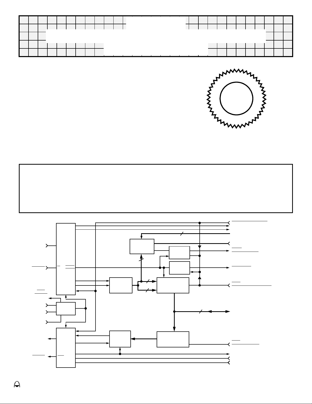
The Aeroflex Circuit Technology Model ARX2412 Manchester Converter is a self contained, 48pin,
triple-in-line hybrid package designed to perform: encode, decode, logic and control functions in a
MIL-STD-1553, A and B multiplex data system. It Provides the necessary interface between transceivers and
a three state parallel 16 bit bus of the protocol logic section of a subsystem remote terminal or controller.
RECEIVER
SECTION
RX DATA
RX DATA
CLK1
OUTPUT
12MHZ
CLOCK 1
INPUT
12MHZ
CLOCK 2
INPUT
12MHZ
CLOCK
SELECT
TX DATA
TX DATA
TRANSMITTER
SECTION
SYNC
BUSY
IN
DECODER
VALID
IN
WORD
SERIAL
OUT
SELECT
CLOCK
LOGIC
SERIAL
OUT
ENCODER
BUSY
OUT
SYNC
ENABLE
CLK
CLK
IN
CLOCK
SERIAL
DATA
SERIAL
DATA
CLOCK
5 BITS
ADDRESS
RESET
SERIAL TO
PARALLEL
SHIFT
REGISTER
PARALLEL
TO SERIAL
SHIFT
REGISTER
ENABLE
RECOGNITION
REGISTER
BITS 0-4
BITS 5-15
BITS 0-4
VALID
CLK
CLK
3 STATE LATCHES
3 STATE LATCHES
VALID
ADDRESS
REGISTER
VALID
WORD
REGISTER
3 STATE ENABLE
AND BUFFER
3 STATE OUT
3 STATE IN
AND BUFFER
3 STATE ENABLE
16 BITS
Figure 1 – FUNCTIONAL BLOCK DIAGRAM
POC POWER ON CLEAR
RECEIVER SYNC TYPE
BUSY RECEIVE
OWN ADDRESS 5 BITS
B0-B4, MSB-LSB
COMMAND SYNC CLEAR
(ADDRESS REGISTER CLEAR)
VU INT
(VALID ADDRESS)
VALID WORD
SACK
(SYSTEM ACKNOMLEDGE)
TO / FROM 16 BIT PARALLEL BUS
BITS DB0 - DB15
MSB - LSB
OSEL
(OUTPUT SELECT)
TRANSMITTER BUSY
SYNC SELECT
ENCODER ENABLE
eroflex Circuit Technology – Data Bus Modules For The Future © SCD2412 REV C 10/19/98
Aeroflex Circuit Technology SCD2412 REV C 10/19/98 Plainview NY (516) 694-6700
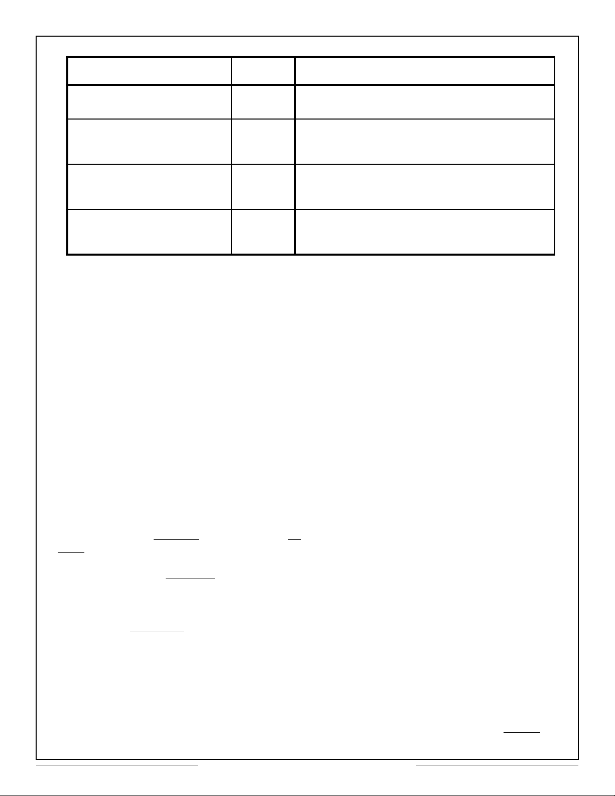
Specifications
Parameter Units Value
External Clock
Oscillator Type (12MHz) TTL As per MIL-STD-1553 A/B long and short term
Power Supply Characteristics
Voltage Input
Current
Thermal Characteristics
Operating Current
Storage Current
Physical Characteristics
Weight
Size
Vdc
mA
°C
°C
oz
in.
+5.0 ±5%
200 max
-55 to +125 (Case Temperature)
-55 to +150
0.7 (20g) approx.
1.7 x 1.1 x 0.2 (43 x 28 x 5.1 mm)
Theory of Operation
This section provides a detailed functional
description of the MIL-STD-1553A/B
Command/Response Manchester II converter
(hereinafter referred to as Converter) and is
intended for use with the timing diagrams shown
in Figures 2 and 3.
GENERAL
POWER ON CLEAR (POC): A logic "0" input
applied at turn-on initializes all of the internal
logic. This signal clears the encoder/decoder
internal counters and initializes the encoder and
decoder functions. This can also be used to abort
a transmission.
DECODER OPERATION
An seen in Figure 1, Functional Block Diagram,
the converter interfaces directly with the
MIL-STD-1553 transceiver by mans of four lines,
namely Tx DATA, Tx DATA
DATA. In the decode mode of operation, the
converter normally needs logic lows (OFF Mode)
on Rx DATA and Rx DATA
MIL-STD-1553 data bus is active, the
MIL-STD-1553 transceiver will output signals that
are similar to those illustrated in Figure 2 (Rx
DATA and Rx DATA
Approximately 5µsec after the converter has
detected the first transition change in, the Rx
DATA input line, the Received Busy output line will
activate from a low to high state and remain high
for 16µsec. During this period, the internal
Encoder/Decoder is shifting serial data out and
the information is being clocked into an internal 16
bit serial to parallel shift register. The Receiver
, Rx DATA, and Rx
. Whenever the
) to the converter.
Busy line will go low after 16µsec, and will remain
low for 4µsec if another 20 bit word immediately
follows the first word. The second word will cause
Receiver Busy to go high for another 16µsec time
interval, This sequence continues until no
additional information is to be processed.
At approximately the same time as the first
Receiver Busy low to high transition, the Receiver
Sync Type line will go high if a command or status
sync field is detected by the internal decoder. It
too will remain high for 16µsec. If a data sync field
is detected by the decoder, the Receiver Sync
Type line will remain in the low state. During the
receiver busy time the decoder shifts serial data
out to the serial to parallel shift register,
regardless of whether the data is valid or not.
However, the stored data is not shifted into the
3-state output buffer unless a Valid Word
indication occurs. This signal is designated Valid
Word. Valid Word performs three functions within
the converter: strobes the 16 bit parallel word into
the 3-state output buffer, strobes the address
recognition function and indicates to the
subsystem user that a valid 16 bit word is now
ready to be processed. A high to low transition on
the Valid Word line will indicate the receipt of a
Valid Word.
The first five bits of a 16 bit command word
represent the terminal address. The bits are
decoded, shifted through the serial to parallel shift
register and compared to the five lines in the
address recognition register (own address, B0
(MSB) thru B4). If a command word is received,
and the own address lines and decoder remote
terminal address bits correspond, and Valid Word
occurs, then a Valid Address Signal (VU INT
) will
2

Aeroflex Circuit Technology SCD2412 REV C 10/19/98 Plainview NY (516) 694-6700
occur going from a logic "1" to logic "0". This signal
transitions at the same time as Valid Word. Upon
detecting a Valid Word output, the user subsystem
must respond with a signal called System
Acknowledge (SACK). A high to low input to the
converter will set both Valid Word and VU INT
occurred) to their original high states. These two
outputs are then ready to analyze the next received
20 bit word. At the same time, SACK will enable the
output 3-state buffer for data readout on the 16
parallel data lines. The user subsystem has up to
20µsec to process the data before the next 20 bit
word is ready to be latched in the output buffer. A
return to the high state on SACK will cause the
3-state output buffer to return to the high impedance
state, completing the conversion of one 20 bit word.
(if
transmit cycle. To terminate a transmission, the
Encoder Enable line must be brought low on or
before the high to low transition of the current
transmitter busy signal.
The remaining signal that is required to make the
converter encoder operate properly is the Sync
Select input signal. Sync Select is an input from the
user subsystem for the purpose of setting the
appropriate sync field polarity to correspond with
the word to be transmitted. A high on this line will
create a command or status sync field, and a low
will result in a data sync field. Initially it should be
set to a Logic "1" before the encoder enable line is
set high, and remain high no later than the high to
low transition of the transmitter busy signal.
The command sync clear input signal is required to
initialize the converter internal logic, set by
detection of command or status sync. It also resets
Valid Word logic. This input signal must be applied
each time a receiver sync type transitions, low to
high, occurs but must not occur until the Valid Word
transitions high to low. Under certain
circumstances, valid address transition may not
occur after a valid sync field is recognized.
ENCODER OPERATION
In the encode mode of operation (Figure 3), the
converter normally provides logic highs (off mode)
on Tx DATA and Tx DATA
provide output data in complementary serial phase
modulated format to the MIL-STD-1553 transceiver
during a transmission. To effect a transmission from
the converter, the sequence of events is to first load
16 bit parallel data into the 3-state input buffer. This
is achieved by the presentation of an input pulse of
logic zero on the Output Select (OSEL) line. Data to
the converter must be stable when the OSEL
occurs. When the XMTR busy signal goes from low
to high, the OSEL may be activated to load the next
16 bit word in preparation for transmission.
Next, the user subsystem must bring the Encoder
Enable line high to initiate a transmission. Encoder
Enable can be conveniently triggered from the
leading or trailing edge of OSEL but must remain
high for 1.0µsec after the trailing edge of OSEL.
If the Encoder Enable line is allowed to remain high,
successive transmissions will result. The transmitter
busy line will go high for 16µsec every time a 20 bit
word is processed through the internal Encoder.
Transmitter Busy indicates to the user subsystem
that control logic is shifting data from the parallel to
serial data buffer to the bi-phase encoder during a
. These two signal lines
Appplication and Operation
Information
General
LOGIC COMPATIBILITY
Direct logic compatibility exists with transceiver
types which have logical low receiver outputs at
times when the bus is not active, such as Models
ARX3402/4402 and ARX3411/4411. Use with
logical high receiver output devices, such as
Aeroflex Models ARX3231/3232 or ARX3404/4404
will necessitate utilization of inverters between
transceiver RX outputs and Model ARX2412 RX
inputs.
POWER ON CLEAR (POC)
A low on this input line resets all internal registers
and initializes the Manchester Converter for
transmission of complete messages.
DATA I/O (DB0-DB15)
The 16 bits of input and output are three state lines.
Impedance of the receiver section latches is high
during transmit cycle. Latched data can be retained
for up to 20µsec. during input of next data word.
TERMINAL ADDRESS LINES (B0-B4)
Addressing the 5 bit address lines is done by hard
wiring. Internal pull up resistors allow logic "1" lines
to be open circuited. Logic "0" lines must be tied to
ground. When a valid command word incorporating
the proper address is received at the input it will
cause VU INT
to go low.
3
 Loading...