

Page 1
Rev 1.3 27/04/2007
ACTpro mifare product range
1040/1050
General Wiring information
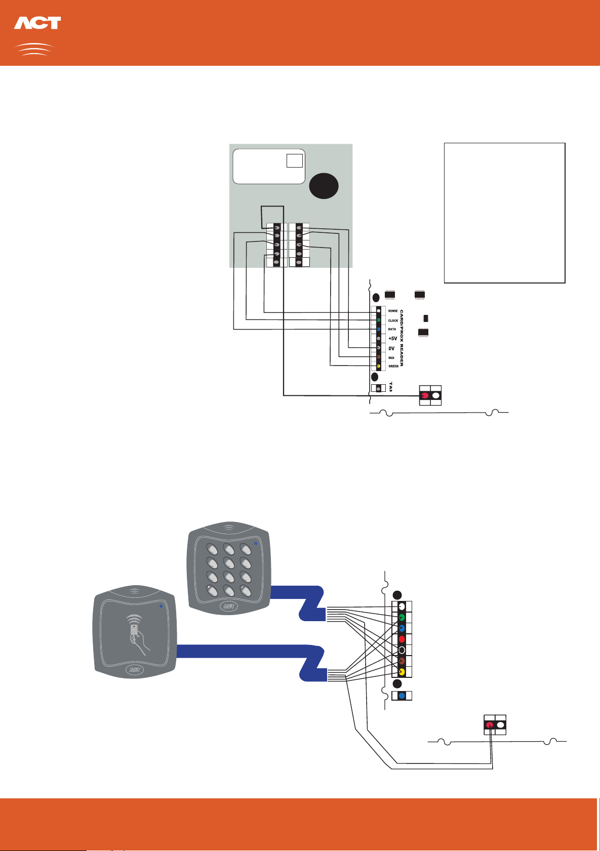
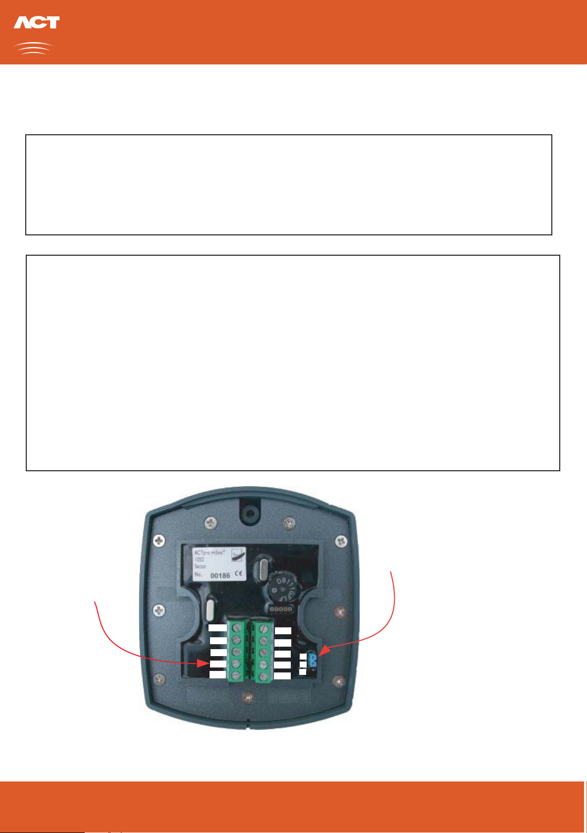
Connection block view of ACTpro mifare 1040/1050.
Wiring for Reader
Powering on the reader requires 12V and 0V
to be Connected.
Data read from a card is presented on the
Data/Clock pins. If configured for wiegand
output the D0 signal is available on Data and D1
is available on Clock.
The Sense signal is driven low when the
reader outputs Clock and Data information, this
can be used to distinguish between Entry and
Exit (see below)
The Internal buzzer is activated by applying
0V to the Buzz. The buzzer activates 4 seconds
after the 0V is applied and sounds continuously
till the 0V is removed.
The Red/Green led is activated by applying
0V to the respective Red/Grn input.
READER MUST BE POWERED FROM 12vDC
ACTpro mifare
1040
Sector
No: 00005
125VAC
30VDC
+12V
Data
Clock
Sense
Buzz
Test
0V
Red
Grn
A
B
White
Green
Blue
Red
Black
Brown
Yellow
Orange
No Connect
No Connect
SENSE
CLOCK / D1
DATA / D0
12V
0V
RED
GREEN
BUZZER
A
B
The standard wiring colours for
ACTpro proximity and pin readers
is shown above.
0V
+12v
Wiring for Entry/Exit Readers
2 31
5 64
8 97
0
ACT
mifare
ACT
mifare
ACTpro mifare 1040 Proximity Reader (Exit)
To make a reader an exit reader leave the Sense line unconnected.
To make a reader an entry reader ensure the Sense line is connected.
PAGE 1
ACTpro mifare 1050 Pin and Proximity Reader (Entry)
Controller
CARD/PROX READER
SENSE
CLOCK
DATA
+5V
0V
RED
GREEN
0V
+12v
READER MUST BE POWERED FROM 12vDC
U nit C1, S outh City B us ines s C enter, T allaght, Dublin 24, Ireland.
Telephone: +353 1 466 2570. Telefax : 353 1 452 0427. E -mail: s ales @ accesscontrol.ie W eb: w ww.acces scontrol.ie
Page 2
ACTpro mifare product range
1040/1050
Reader Configuration
Clock and Data
Default Output Format is Clock and Data (also know as Magnetic Stripe Track/2 or ABA). Using this default format the data is
encoded as 10 BCD digits .
Wiegand
The reader can be configure to output the data in wiegand format instead of clock and data. Connecting the Sense line to OV
before powering on the reader will switch the unit to wiegand output mode. The reader will output 37 bit wiegand.
The ACTpro mifare 1040/1050 can operate as a sector or serial reader, selectable via a jumper.The default position of the jumper
is for sector operation (jumper on pins 1 and 2).
Sector Reader
The default sector reader operation of ACTpro mifare readers is to read the batch numbers that are encoded into Sector 1
from the mifare Cards and Fobs issued by ACT.
However the readers can be programmed to read any specified sector data, this allows the readers to be installed on sites that are
already using mifare cards. See next page for more details on reader re-programming.
Serial Reader
When in Serial Reader mode the card serial number of any mifare card that is presented is read. The reader may be placed in
serial mode linking pins 2 and 3 together and reapplying power to the board, link should be left in place. TheACTpro mifare
reader can also provide the Serial number Byte Reversed, in this case remove the jumper and re-apply power to the reader.
OUTPUT DATA FORMAT
SECTOR/SERIAL OPERATION
To select Wiegand Output connect
SENSE and 0V together.
Power must be reapplied for
Sector/Serial Operation Jumper.
change to take effect, connection
should be left in plac
12Vdc
Data
Clock
Sense
Buzz
0V
Red
Grn
Sector Operation: Jumper Pins 1 and 2
1
2
A
3
B
Serial Operation: Jumper Pins 2 and 3
Serial Operation (Byte Reversed): Remove Jumper
PAGE 2
Unit C1, South City Business Center, Tallaght, Dublin 24, Ireland.
Telephone: +353 1 466 2570. Telefax: 353 1 452 0427. E-mail: [email protected] Web: www.accesscontrol.ie
Page 3

ACTpro mifare product range
1040/1050
Power On Beep Codes
The Output Data Format and the Sector/Serial Operation of the reader can be determined by the beeps generated by the
reader after power is applied. The reader will generate two sets of beeps, the first indicating the Output Data Format and the
second set of beeps indicates Sector or Serial Operation. The first set of beeps will occur while the Led is Green, the second
set of beeps occur half a second later while the Led is Blue.
First Beep Set: Double Beep: Sector Reader
Single Beep: Serial Reader
Triple Beep: Serial Reader (Byte Reverse)
Second Beep Set:Double Beep: Clock and Data Output
Single Beep: Wiegand 37 bit Output
Note: If the reader has been re-programmed (see next page), then a serial of notes is played after the Second Beep Set, this
indicates that the readers default programming to read ACT mifare cards has been changed.
Reader Reprogramming
The ACTpro mifare 1040/1050 readers ship from the factory pre-configured to read the mifare Cards and Fobs supplied by ACT.
On sites with an existing installation of mifare cards, it will probably be necessary to reprogram the ACTpro mifare 1040/1050
so that the data on the existing cards maybe read.
The configuration required by ACTpro mifare 1040/1050 to read the existing mifare cards is given to the ACTpro mifare 1040/1050
via a programming card.
The programming card contains the complete information about how to access the data on the existing mifare cards. Programming
cards may be supplied by ACT or they can be generated on site if ACTWinPro/ProLite is installed and an ACTpro mifare usb reader
is used.
To reprogram an ACTpro mifare reader the programming card must be presented to the ACTpro mifare reader after power up and
while the Led is Red. The ACTpro mifare will acknowledge the re-programming by playing an ascending note tune.
The configuration is held in non-volatile memory and so is held even if the reader is powered down. Readers that have been
reprogrammed may be reset to read ACT issued mifare Cards and Fobs with a ACT Default Programming Card.
ACTpro mifare readers that have been programmed to read none ACT mifare Cards and Fobs will play a series of ascending
notes after being powered up in addition to the standard beep codes, this is to indicate that it no longer reads the mifare Cards
and Fobs issued by ACT.
Please see the "Application for an ACTpro mifare reader programming card" document for deatils on obtaining a programming
card.
Page 3
U nit C1, S outh City B us ines s C enter, T allaght, Dublin 24, Ireland.
Telephone: +353 1 466 2570. Telefax : 353 1 452 0427. E -mail: s ales @ accesscontrol.ie W eb: w ww.acces scontrol.ie
Page 4
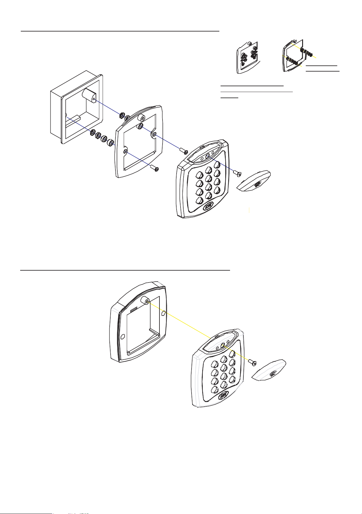
Mounting Instructions for Flush Mount Unit
Spacers break
away from main
component when
required by
installer for use.
View showing
spacers stacking
View showing mounting plate
before spacers are broken away by
installer.
Note:
Determine the distance between the patress box
and the mounting plate, using the spacers that are
labelled 1mm to 4mm. A spacer of the correct
length is assembled by stacking the spacers
together.
Screws
Standard pattress
box.
Mounting plate is attached to the pattress
ox using the screws supplied. Ensure
the corect spacers have been used to
bridge the gap between the mounting
plate and the fixing wings of the pattress
box to avoid the mounting plate being
distorted.
Place the Reader / Keypad onto the surface mount
collar and clip down into place.Use the security
screw supplied to attach the unit to the surface mount
collar.
Mounting Instructions for Surface Mount Unit
Security screw supplied with
the unit.
Place the cap onto
the unit and push
firmly into place.
The surface mount collar is
mounted on the wall using
the fixing kit supplied in
the box.
PAGE 4
Security screw supplied with
the unit.
Place the cap onto
the unit and push
firmly into place.
Place the Reader / Keypad onto the
surface mount collar and clip down into
place.Use the security screw supplied to
 Loading...