

Page 1
Power
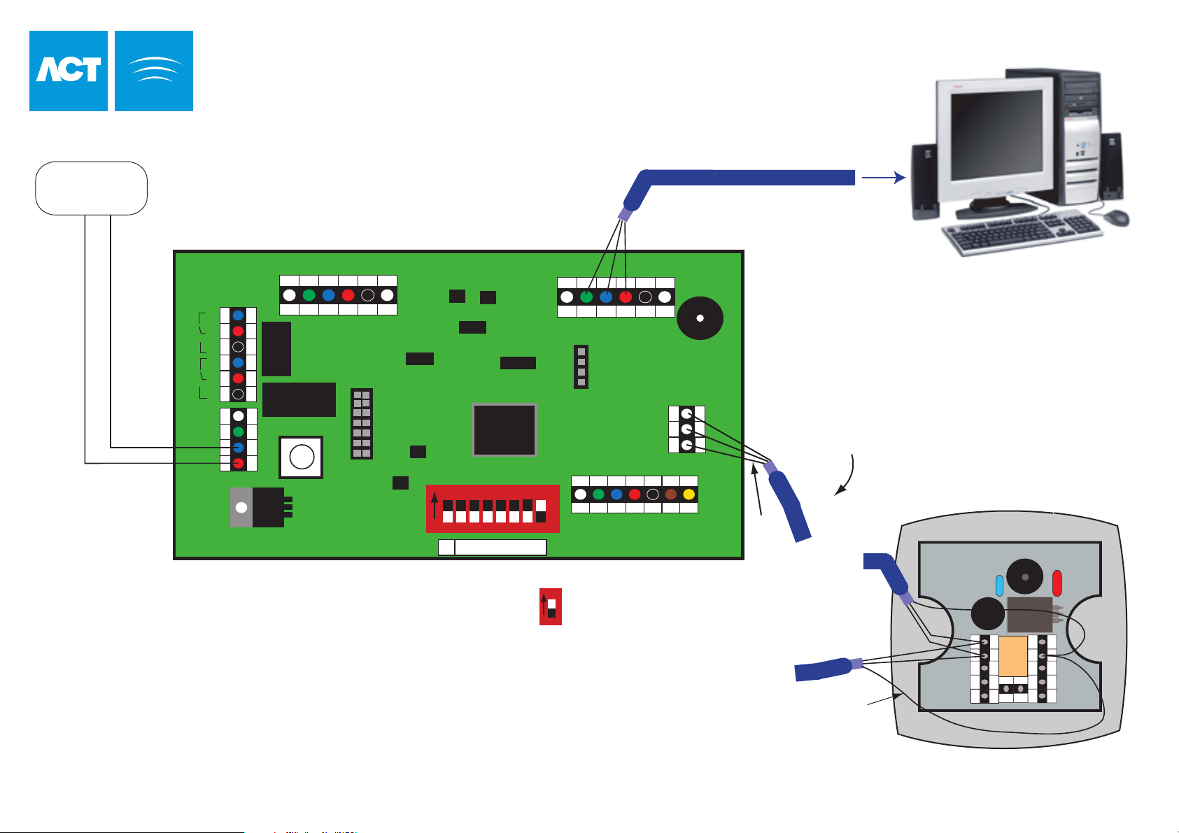
Supply Unit
ACTSmart Controller Installation
3metres Direct Connect Cable (Supplied)
ACTSmart Controller
OP3 OP4 0V IP1 IP2 IP3
N/C C
+12V
OP2
OP1
TAMPER
MAINS
PRESENT
+
12V DC
N/ON/C C N/O
-
5A 250VAC
5A 30VDC
5A 250VAC
5A 30VDC
0V
FACTORY DEFAULT
This unit should be reset to its
factory default condition before
Note:
Tamper and Mains Present
are not used.
installation. To do this, power
the unit up with ALL switches in
the OFF position. The two LED's
will illuminate for about 2 sec.
The correct switch settings may
LED Functionality:
Red LED indicates the status of communications with the PC.
Green LED indicates the status of communications with the ACTSmart Units.
Normally they flash rapidly.
If there is a problem they will flash slowly (about once a second).
then be set.
1 2 3 4 5 6 7 8
On
N ADDRESS
SERIAL NETWORK
DTR RX TX 0V B A
SENSE
CLOCK
DATA
+5V
8
To connect to PC set
DIP 8 to the ON position
On
www.accesscontrol.ie
A
B
0V
0V
RED
GREEN
Continue daisy chain to
remaining ACTSmart2
units (maximum 8).
SLAVE
Shield
Total cable length
maximum 1.4km
Network cable is single
shielded twisted pair,
Belden 9501 or similar
Programmable Input
Shield
ACTWinSmart Software
1A 125V
RON
Aux I/O 2
Aux I/O 1
5A
5A
B
A
ACTSmart2 Unit
OMRON
C
D
=
12V
RELAY
5A/250V ~AC
Tamper
12V DC
0V
N/O
COMM
N/C
+
See ACTSmart2 Installation
Manual for connection details.
18-00036
 Loading...