

Page 1

ACT1000 Installation Diagrams
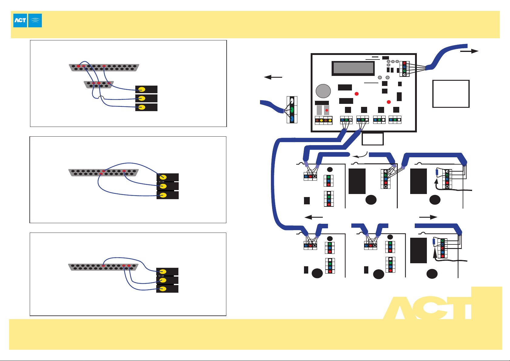
Typical ACT1000 Configuration
Card or Proximity
Reader
Volt Free
Tamper Contacts
Sense
Card/Prox Reader
Clock
Data
+5v
0v
Red
Green
BATCH: 96XX-1
TAMPER
PRODUCT: ACT 1000 REV1.1
SERIAL NUMBER: 00XXXX
0123456789
Important!
Always Place Varistor
Across Lock Terminals
Network Printer
0V
TX
RX
Timekeeper
Lithium Battery
Push Button
Door Contact
Inter Lock
0V
OP2
OP3
Buzzer
12V+
DC-
Relay
N/C
N/O
OMRON
5A 250VAC
5A 30VDC
Card or Proximity
Reader (Entry)
(standalone)
A
B
Card or Proximity
Reader (Exit)
2 31
5 64
8 97
0
Wiring for Entry/Exit Readers
Controller
Sense
Card/Prox Reader
Clock
Data
+5v
0v
Red Led
Grn Led
Door Contact
The above diagram is valid only
Wire both readers in parallel but leave
Wiring for Clock and Data / Wiegand Reader
the SENSE line on the Exit reader unconnected.
For Wiegand readers .
Door
Release
Button
+12V
Power
Supply
Unit
0V
C
ENTRY READER
Wire both readers in parallel but connect D0
line of the exit reader into the SENSE line on
the controller,leave the SENSE line on the
Exit reader unconnected.
ACT20 Pin Pad Wiring Diagram
OR
A
NGE
Cable: 8 Core Screened,
Max 30m
D
RE
OPTIONAL EXIT READER
SENSE
UNUSED
NGE
A
OR
0V
INTERLOCK
(PB2)
PUSH
BUTTON
B
L
A
CK
DOOR
CONTACT
YE
L
LO
B
W
RO
W
N
BATCH:
PRODUCT:
SERIAL NUMBER:
0 1 2 3 4 5 6 7 8 9
TAMPER
98XX-1
ACT20 REV2.1
012345
12-24V
+
AC/DC
-
0V
BUZZER
OP3
TE
WHI
E
OP2
BLU
N
E
E
R
G
The ACT20 connects in parallel
between the reader and the controller.
An extra line (ORANGE) is used to
bring +12VDC power to the ACT20.
The shields should be joined.
for clock-and-data type readers.
White
Green
Blue
Red
Black
Brown
Yellow
Orange
Connect to
12Vdc
ENTRY/EXIT READER
Controller
Controller Cable ACT20
Sense White Buzzer
Clock Green OP2
Data Blue OP3
+5V Red
0V Black 0V
Red LED Brown Door Contact
Grn LED Yellow Push Button
+12V Orange +12V
Sense
Clock / Data1
Data / Data 0
+5v
0v
Red Led
Grn Led
(Buzzer Ctrl)
Unit 8 Tallaght Business Centre, Whitestown, Tallaght, Dublin 24, Ireland.
Telephone: 353 1 462 2585. Telefax: 353 1 462 2587. E-mail: sales@ accesscontrol.ie Web: www.accesscontrol.ie
Page 2
ACT1000/2000 PC / Printer and Modem Cables
ACT Network Wiring
DB25 Female
(Rear View)
DB9 Female
(Rear View)
Direct Connection Cable (PC to Controller)
2 3 7
12345
6789
ACT 1000/2000
3 Way Pluggable
0V
TX
RX
Max cable length is 5m using standard alarm cable
or 30m using twin twisted-pair (use 0V in each pair)
Serial Printer Cable
DB25 Male
(Rear View)
7
20
3
ACT 1000/2000
3 Way Pluggable
0V
TX
RX
Max cable length is 5m using standard alarm cable
or 30m using twin twisted-pair (use 0V in each pair)
To Mains Supply
Network cable is single
shielded twisted pair,
Belden 9501 or similar
NETWORK
ACT Nework Interface Card
RS232
PORT
RS485
RS485
232 Interface
Converter
Connections for 9 Way
SCN C DI DO
LED2
LED3
Line 2
Line 1
L E N
+BAT-
~AC~
B
A
A
A B OV
ACT 2000 ACT 1000 ACT 1000
B
0V
DTR
RX
TX
0V
Each line may be up to 1.4km in length
and connect up to 32 controllers
C 1 2
DOORS
SERIAL/PRINTER
C 1 2
C = SHIELD
1 = B
2= A
To next door
Timekeeper
Lithium Battery
Line 4
Line 3
C 1 2
C 1 2
All lines are equivalent and operate in parallel
Any controller may be connected to any line.
Network cable is single shielded twisted
pair: Belden 9501 or similar
NETWORK PRINTER
A
B
0V
TX
RX
Timekeeper
Lithium Battery
Connector of PC
SCN = Pin 5
C = Pin 7
DI = Pin 3
D0 = Pin 2
NETWORK PRINTER
To PC
A
B
0V
TX
RX
Shield
120R Resistor
on last node.
Serial Modem Cable
DB25 Male
(Rear View)
7
A
A B OV
B
0V
DTR
A
B
RX
TX
0V
NETWORK
Doors
Serial/Printer
(Modem to Controller)
2
3
ACT 1000/2000
3 Way Pluggable
NETWORK
0V
TX
ACT 2000
A
A B OV
ACT 2000
B
0V
DTR
Doors
A
B
Serial/Printer
RX
TX
0V
Network printer
Timekeeper
Lithium Battery
ACT 1000
A
B
0V
TX
RX
Shield
120R Resistor
on last node.
RX
Max cable length is 5m using standard alarm cable
or 30m using twin twisted-pair (use 0V in each pair)
Unit 8 Tallaght Business Centre, Whitestown, Tallaght, Dublin 24, Ireland.
Telephone: 353 1 462 2585. Telefax: 353 1 462 2587. E-mail: sales@ accesscontrol.ie Web: www.accesscontrol.ie
 Loading...