

Page 1
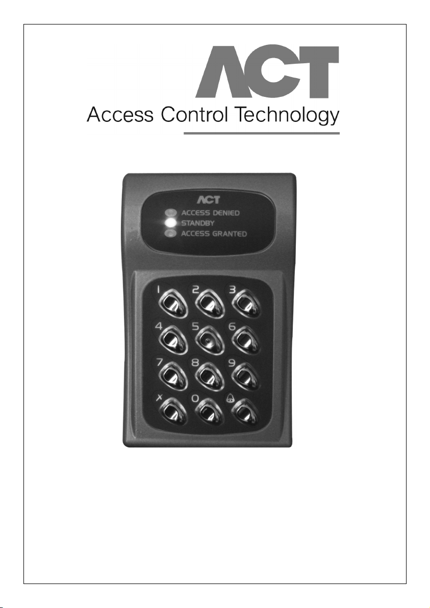
ACT 10 Digital Keypad
Operating & Installation Instructions
18-00001
Page 2

ACT 10 Digital Keypad Operating & Installation Instructions
Installation Notes
• Always remember to factory default the controller before you start programming.
• Always remember to place the supplied Varistor across the terminals of the lock terminals to protect
the relay contacts.
• Never use the onboard relay to switch AC mains voltage. An external relay isolated electrically from
the ACT 10 should be used for this purpose.
• Don’t forget to change the programming code to something known only to yourself.
Important: As with any Access Control system, always ensure there is an alternate means
of escape in the event of the unit failing to operate due to power loss or in the event of fire.
Product Specification
Number of Users 10 PIN Codes
Supply Voltage 12 – 24 Volts AC or DC
Current Consumption 40mA (nominal), 120mA (maximum)
Operating Temperature -10 to +50 degrees C
Door Open Time 0 - 255 seconds
Relay Contact Rating 5A / 250Vac
Controller Size
Controller Weight 700 grams
Installation Indoor or Outdoor (IP54)
Mounting Surface or Flush
Output Rating 100mA
(H x W x D): 138 x 87 x 37 (mm)
Ordering Information
ACT 10 Digital Keypad ACT 10
ACT 10 Flush Kit ACT 10 FK
ACT 10 Weather Shield ACT 10 WS
2
Page 3

ACT 10 Digital Keypad Operating & Installation Instructions
30 Second Programming Guide
(For typical Standalone System)
1. Enter Programming Mode
On the digital keypad press button
will flash yellow / orange.
2. Change User 1 Code
On the digital keypad press button 0, then press 1. Input the new User 1 code (4 digits)
3. Change Programming code
On the digital keypad press button 0. Press . Input the new programming code (4 digits)
4. Exit Programming Mode
On the digital keypad press button
exited.
The ACT 10 Digital Keypad is now ready for normal use.
Note: The ACT 10 Digital Keypad may be returned to its factory default condition at any time by
entering the programming mode and pressing the
. Input the programming code (default is 9999). The LED
✘
. The LED turns red and programming mode has been
✘
button three times
.
For Door 2 Operation
1. Enter Programming Mode
2. Change User 2 Code
On the digital keypad: Press Button 0, then Press Button 2 (for User 2). Input the new User 2
code (4 digits)
3. Assign User 2 to Door 2
On the digital keypad: Press Button 1, then Press Button 2 (for User 2), then Press Button 2 (for
Door 2).
4. Exit Programming Mode
User 2 code will now activate Door 2 Relay.
ACT 10 Digital Keypad Programming
Press the✘button followed by the programming code (initially 9999). The yellow LED will flash while
in programming mode. To exit the programming mode press button
occurs automatically if no key is activated for 30 seconds.
3
. Exit from programming mode
✘
Page 4

ACT 10 Digital Keypad Operating & Installation Instructions
Changing Codes: Enter Programming Mode, then Press
Step Keypad Entry Operation Example: Assign code 7529 to user 7
1 0 Change Codes
2
0-9, User Number 0-9, = programming code 0 Change Codes
3 0000(00)-9999(99) 4 digit code – 0000 deletes User code 7 User 7
9999 Enter programming
✘
7529 PIN code
✘
Exit programming
Default User Codes:
Programming Code: 9999(99); User 1 Code: 1234(56). All others are inactive.
Setting Switched Output Combinations: Enter Programming Mode, then Press
Step Keypad Entry Operation Example: Assign Toggle to User 7
1 1 Set Outputs
0-9 User number 0-9, 1 Set Outputs
2
3 0-7 Output function code 7 User 7
Output Function Code Door Output Door 2/Output 2 Output 3
0 Toggled
1 Timed
2 Timed
3 Timed Timed
4 Timed
5 Timed Timed
6 Timed Timed
7 Timed Timed Timed
9999 Enter programming
✘
0 Door Toggle
✘
Exit programming
Default function code is 1 (Relay Timed) for all users. When the door is toggled open, this will
be indicated by the green indicator flashing.
Setting Timers: Enter Programming Mode, then Press
Step Keypad Entry Operation
12
2 0 - 4 (Timer number) Buzzer sounds indicating timing. wait required period.
3 (Stop timing) Buzzer stops – timer set.
Timer Number Function Default
0 Relay time 5s
1 Door 2 / Output 2 time 5s
2 Output 3 time 5s
3 Door Ajar time 30s
4 Guest Buzzer time 2s
Timers may be set to any duration between 2 seconds and 4 minutes.
Set Timers
4
Page 5

ACT 10 Digital Keypad Operating & Installation Instructions
Setting Configuration: Enter Programming Mode, then Press
Step Keypad Entry Operation
30-37 or 40-47 option number
1
2 0 or 1 1= Set, 0 = Unset
Option Function Default Operation
30 Door Chime Off When set, whenever the door contact is opened, the built-in buzzer makes a
31 Silent Operation Off When set, the keypad operates silently. No audible tones (key-presses or
32 Permanent On When set (default), the keypad illumination is always on. This option will
Backlighting override option 42 (Auto backlighting)
33 Locksaver Off When set, and when the relay is active (following a valid code or button release),
(Anti Tailgating) the relay timer is truncated to 2 seconds when the door contact opens. This
34 Alarm Off When set, the keypad may be used as a remote keypad for an alarm system. The red
Keypad and green indicators are controlled by the door contact and the release button inputs
Operation inputs respectively, and the built in buzzer is controlled by the interlock input.
35 Interlock Off When set, two or more keypads may be interlocked so that only one controlled
36 Six Digit Codes Off When set, all user codes, and the programming code, are six digits long. The
37 Twin Codes Off When set, two different codes must be entered within 15 seconds in order to
40 Door Forced Off When set, the buzzer output is activated, if the door contact opens when a valid
Alarm code has not been entered. The output is deactivated when a valid code is next
41 Group Disable Off When set, the top five user codes (5-9) are inactive any time the interlock input
42 Auto Off When set, the keypad illumination is normally off, but will switch on in
backlighting response to any key being pressed or while in programming mode. This option
43 Door Ajar Off When set, and the door contact has been open for longer than the time programmed
Alarm into the door ajar timer, the built–in and external buzzers sound intermittently. The
44 Guest Button On When set (default) and when the
45 Fire Alarm Off When set, the relay is held active whenever the interlock input is active, and
Override the green indicator will flash. This is useful for allowing a fire alarm system
46 Release Button Off When set, the interlock input activates the door 2 relay which follows output 2’s
47 Duress Off When set, and when a duress code is entered, the door is opened normally and
chime sound and the buzzer output activates for 2 seconds.
confirm tones) are produced from the built-in buzzer function.
ensures that irrespective of programmed relay time, the door will be locked
as soon as it closes, and any person following will have to enter a code.
door may be open at any one time. The interlock output is active whenever the
relay is active or when the door contact is open. When the interlock input is
active, the release button and all codes are inactive, the red indicator flashes.
The interlock outputs and inputs of any number of keypads may be combined
on a single wire.
default user one code becomes 123456 and the default programmer code
becomes 999999.
open the door. The outputs activated are those which have been programmed
for the first code to be entered.
entered. This is useful for monitoring fire doors etc.
is activated. This restricts access to certain codes under external control (i.e. an
alarm system output or a time clock).
is overridden by option 32 (permanent backlighting). To prevent any
illumination, unset options 32 and 42.
buzzers may be silenced by closing the door and entering a valid code.
button on the keypad is pressed, the buzzer
output is activated for the duration programmed into the guest buzzer timer.
to override controlled doors.
timer for Second door. This allows two doors to be controlled using one keypad.
output 2 is activated. A duress code is any valid user code with one added to
the last digit. The output will be reset when a valid user code is entered. When
the duress option is set, user codes which have 9 as the last digit should be
avoided as there is no corresponding duress code.
5
Page 6

ACT 10 Digital Keypad Operating & Installation Instructions
!
OM
R O
N
5A
25 0V
AC
5A
30 V
DC
012 345 678 9
Important
Always Place Varistor
Across All Lock Terminals
+V
+V
0V
Volt - Free
Tamper Contacts
Door Contact
Door Release
Button
Guest Buzzer
Output sink = 100mA max
Power Supply
12-24V ACDC
12-24
AC/DC
-
+
N/C
N/O
C
0V
Buzzer
OP3
Duress
OP2
Interlock
OUTPUTS
INPUTS
0V
Interlock
(PB2)
Push
Door
Contact
Button
TAMPER
LK1
Se ria l N o. 123 45
Ba tch : 2 0xx -1
Pr odu ct: ACT 10 Rev 3.0
N/C
N/O
C
+V
0V
Door Release Button
for Door 2
RELAY
DOOR 2
OM
R O
N
5A
25 0V
AC
5A
30 V
DC
Door 2
12-24V ACDC
Power Supply
Shows connection for normally
energised lock, (e.g. magnetic lock).
Shows connection for normally
DE-ENERGISED lock, (e.g. door-strike).
Break Glass
Unit (optional)
Power up without link if
Programming Code has
been lost
Shows connection for normally ENERGISED
lock (e.g. magnetic lock)
The ACT 10 may be used to control 2 doors as illustrated in the diagram above
Figure 1: Typical ACT 10 Configuration
Figure 1: Typical ACT 10 Configuration
Incorrect Code Lockout When three invalid codes have been entered in a row, the keypad will enter
lockout mode for 20 seconds. During this time, the red LED indicator will flash and all PIN codes will be inactive.
Restoring Factory Defaults
Enter Programming Mode followed by . This restores the ACT 10 Digtal Keypad to its default
settings. If the Programming Code has been forgotten, it may be set to 9999 by:
1. Remove the power from the unit. 4. Replace link LK1.
2. Remove link LK1 at the back of the unit. 5. Proceed with programming.
3. Apply power to unit.
Note: The keypad will not operate correctly without LK1 in place.
6
Page 7

DO silcone all screw mounting positions and cable entry.
DO install a weather shield when the keypad is
1. installed on an uneven surface
2. in an exposed area
DO apply silicone to the top and two sides of the keypad, or shield, when used.
DO NOT apply silicone to the bottom of the keypad as this will block the air
vents and trap any water which may enter the keypad
If a weather shield is fitted the same applies
Figure 2: ACT10 Digital Keypad_Guide to outdoor installation in exposed areas
Figure 1: ACT10 Digital Keypad Schematic
PSU
EXIT
220/240 Volts AC
Tamper 3 Inputs (100mA)
3 Outputs (100mA)
12/24 Volts AC/DC
ACT 10 Digital Keypad Operating & Installation Instructions
Figure 2: ACT 10 Digital Keypad Schematic
Figure 3: ACT 10 Digital Keypad - Guide to outdoor installation in exposed areas
7
Page 8

Installation Instructions for
ACT 10 Flush Mount Kit
• Mount back box into wall void or aperture with wood screws provided
• Ensure that the cable comes through the cable entry in the back box
• Remove back plate from the ACT 10 and mount on to the removable cradle with the 3 bolts
provided again bringing the cable through the rear cable entry in the back plate
• Carefully remove the pluggable connector blocks on the ACT 10 and make the required
connections
• Replace the wired connectors in their correct positions and install the front housing of the
ACT 10 on its back plate. Any excess cable can be shoved back into the void between the
cradle and the back box.
• Secure the ACT 10 to its back plate with the security screw.
• Fit the cradle into the back box.
• Fit the front plate to the back box with the 4 security screws provided.
User List
User User Name PIN Door 1 Door 2
0
1
2
3
4
5
6
7
8
9
This manual and user list is available for download from our website, www.accesscontrol.ie
Unit C1, South City Business Centre,
Tallaght, Dublin 24, Ireland
Tel: 353-1-4662570 Fax: 353-1-4520427 UK Locall: 0845 300 5204
Web: http://www.accesscontrol.ie E-mail: tech@accesscontrol.ie
Copyright © 2007 Access Control Technology Ltd.
 Loading...