

Page 1

Operating & Installation Instructions
for ACT2000 Enhanced & ACT1000
Access Control Units
Page 2

Contents
Default Code ..........................................................................................................1
Menu Navigation Keys..........................................................................................1
Text Entry Keys ....................................................................................................1
OPERATOR MENU..............................................................................................2
User Set-up..........................................................................................3
Enable ....................................................................................3
Disable ....................................................................................3
Assign Names..........................................................................3
Assign Groups ........................................................................3
Assign Options ........................................................................4
Assign PINs ............................................................................4
Learn........................................................................................4
Batch Cards ............................................................................5
One-To-One ............................................................................5
Card Validity............................................................................5
Group Set-up ......................................................................................5
Enable......................................................................................6
Disable ....................................................................................6
Assign Names..........................................................................6
Access Rights ..........................................................................6
Assign Options ......................................................................7
Assign PINs ............................................................................7
System Log ..........................................................................................7
Display Log ............................................................................7
Print Log ..................................................................................7
Recommended Printer / Printer Settings ................................8
Filter Log (ACT2000 Only) ..................................................8
Control Door ......................................................................................8
Lock Door................................................................................8
Unlock Door............................................................................8
Normalise Door ......................................................................8
Pass Door ................................................................................8
AUX output on........................................................................9
AUX output off........................................................................9
User Tracking (ACT2000 Only) ........................................................8
Log in (ACT2000 Only)..........................................................9
Log out (ACT2000 Only)........................................................9
Clear All (ACT2000 only) ......................................................9
Set Date/Time......................................................................................9
Time Zones........................................................................................10
Set Holidays ......................................................................................11
Issue Number ..................................................................................11
Change PIN ......................................................................................11
Page 3

INSTALLER MENU ..........................................................................................12
System Settings..................................................................................14
Operation ..............................................................................14
Display ..................................................................................15
Language (ACT2000 Only) ..................................................15
PIN Length ............................................................................15
Fire Doors..............................................................................15
User Tracking (ACT2000 Only)............................................16
Outputs (ACT2000 Only)......................................................16
Door Settings ....................................................................................16
Operation ..............................................................................16
Alarms ..................................................................................17
Timers....................................................................................18
Timed Actions ..................................................................................18
Communications ..............................................................................18
Set Address ..........................................................................18
Direct Conn. ..........................................................................18
High Speed ..........................................................................19
Slave Mode (ACT2000 Only) ..............................................19
No Hist. Log..........................................................................19
Print All ................................................................................19
Remote Doors (ACT2000 Only) ..........................................19
IO Modules (ACT2000 Only) ..............................................19
Set Password..........................................................................19
Card Set-up ......................................................................................20
Site Code 1 ............................................................................20
Site Code 2 ............................................................................20
Card Format ..........................................................................20
Diagnostic ..........................................................................................20
Version ..................................................................................20
Reader Test............................................................................20
Last Reset ..............................................................................21
Change PIN ......................................................................................21
Factory Default ................................................................................21
Contents
Page 4

Diagrams ..............................................................................................................22
ACT1000 Configuration Standalone ..............................................22
ACT2000 Configuration Standalone ..............................................23
DS100 Door Station Installation......................................................24
Wiring for Entry / Exit Readers......................................................25
ACT20 Pin Pad Installation Diagram ............................................26
ACT1000/2000 PC / Printer and Modem Cables ..........................27
Interlock Configuration ..................................................................28
Fire Override Configuration............................................................28
ACTWinPro Configuration..............................................................29
ACT 4-Line Network Wiring ..........................................................30
ACT Single Line RS-485 Converter................................................31
ACT Modem Configuration ............................................................32
ACT LAN Configuration ................................................................33
Prestel Receiver Wiring....................................................................34
Alarm Panel Integration..................................................................35
ACTPro IOM Input/Outpu Module ..............................................36
ACT System Configuration ............................................................37
Contents
Unit C1, South City Business Centre, Tallaght, Dublin 24, Ireland
Tel:353-1-4662570 Fax:353-1-4520427 Web:E-mail: sales@accesscontrol.ie
http://www.accesscontrol.ie
Page 5

ACT1000/2000 Operating Instructions Issue Number 4.10-00
1
Text Entry
Textual descriptions (user names etc.) are entered via a simple text entry system. Each of the digits
1-9 may be used to enter letters, numbers or symbols according to the table below. Pressing the
required digit once will bring up the first letter in that group. Subsequent presses will step through
the group and then back to the first letter. Pressing the 0 key advances to the next character and
pressing the ✘ key moves back to the previous character. The ✔ key accepts the currently
displayed text. If the cursor is at the first location in the display, pressing the ✘ key gives the
option to cancel all the displayed text.
Operating Instructions for
ACT1000/2000 Access Control Units
All user functions are accessed via two six-digit codes. The first code is for the Operator who is
responsible for the day-to-day administration of the system, adding and deleting users, setting
names and assigning time-zones etc. The second code is for the Installer who performs the initial
configuration of the system and decides on communications settings, interfaces, and modes of
operation.
Default Codes
Operator 123456 Installer 999999
Menu System
All user functions are accessed via a menu system. The menu (or submenu) title appears on the
top line of the display. The bottom line contains the current item in the menu. The three keys on
the bottom row of the keypad are used for navigation:
Menu Navigation Keys
✘ Quit to previous menu Next menu item ✔ Select item or Submenu
Text Entry Keys
1a b c A B C 1 2 d e f D E F 2 3 g h i G H I 3
4j k l J K L 4 5 m n o M N O 5 6 p q r P Q R 6
7s t u v S T U V 7 8 w x y z W X Y Z 8 9 SPC - & . + ‘ / 9 0
✘ Previous Character 0 Next Character ✔ Accept displayed text
Page 6

ACT1000/2000 Operating Instructions Issue Number 4.10-00
2
Operator Menu
User Setup Enable Allow a user or range of users to open the door
Disable Prevent a user or range of users from opening the door
Assign Names Enter a name for each user
Assign Groups Assign users to groups
Assign Options Specify options for each user
Assign PINs Set the individual PIN for each user
Learn Learn randomly coded cards (e.g. Bank Cards)
Batch Cards Assign a batch of cards to a range of users
One-To-One Assign a card to a user
Card V alidity
2
Set a validity period for a user.
Group Setup Enable Allow users in specified groups to open the door
Disable Prevent users in specified groups from opening the door
Assign Names Enter a name for each group
Access Rights Specify what access rights apply to each group
Assign Options Specify output and PIN options for each group
Assign PINs Set the PIN for each Group.
System Log Display Log Show the system log on the display (recent events first)
Print Log
2
Print the system log on an attached serial printer
Filter Log
2
Prevent events entering the system log
Control Door
1
Lock Door Lock door - prevent all cards from opening it.
Unlock Door Unlock door - relay is activated so cards are not required.
Normalise Door Set a door back to normal operation
Pass Door Momentarily open a door for the programmed time
AUX output on Switches the auxiliary output on
AUX output off Switches the auxiliary output off
User Tracking
2
Log in Log a user into the tracking area
Log out Log a user out of the tracking area
Clear All Remove all users from the tracking area
Set Date/Time Set the current date and time for the system
Time Zones Specify the time periods and days which apply to a given timezone
Set Holidays Specify which days within the next year are holidays
Issue Number Set the current system issue level (if issue checking option enabled)
Change PIN Change the PIN used to access the operator menu
Exit from the menu is automatic if no keys are pressed for a period of time.
1
On the ACT2000, you will first be prompted for a door.
2
Only present on ACT2000
Page 7

ACT1000/2000 Operating Instructions Issue Number 4.10-00
3
User Setup
The User Setup menu allows the operator to enable and disable individual users, and to change
the configuration information for each user . In each of the user setup functions, the user is selected
by either using the 0 key to advance to the required user, or alternativ ely by using the numeric keys
1-9 to directly enter the number of the desired user. The top line of the display will show the name
for each user if one has been entered, otherwise the number only will be displayed.
ENABLE
The Enable function allows a user or range of users to be enabled. Pressing the ✔ key enables the
displayed user. This means that the card or token belonging to this user will be recognized and
may be allowed entry to the protected area. Note that the group disable function or programmed
access rights may override an enabled user.
DISABLE
The Disable function allows a user or range of users to be disabled. Pressing the ✔ key disables
the displayed user. This means that the card or token belonging to this user will no longer be
recognized and will not allow entry to the protected area.
ASSIGN NAMES
The Assign Names function allows a 16 character textual name to be assigned to each user
between 1 and 200/2000 (200 on the ACT1000, 2000 on the ACT2000). This name will be shown
with any displayed or printed log events involving this user. Pressing the ✔ key selects text entry
mode.
ASSIGN GROUPS
The Assign Groups function allows a user or range of users to be assigned to a group. On the
ACT2000 any of the 20,000 users can be assigned to one of 1024 groups, the ACT1000 users 1 to
1000 may be assigned to one 16 group. By default, all users belong to Group 1.
The Display will show the user number on the top line and the group that that user is assigned to
on the bottom line. The displayed user number may be advanced by the 0 key. Also any user may
be displayed by entering the user number, and then pressing the ✔ key followed by the ✘ ke y.
Pressing the ✔ key prompts for a group number to be entered, entering the group number and
pressing the ✔ key again assigns the currently displayed user to the group entered.
A range of users may be assigned to the displayed group number, entering the first user number
in the range of users followed by the ✔ key, and then entering the last user number followed the
✔ key will assign all the users in the range to the group displayed. This method can also be used
to assign a single user to a group by entering the same user number for the first and last user in
the range.
All users above 1000 on the ACT1000 al
ways belong to Group 1 (unless programmed via
ACTWinPro).
Page 8

ACT1000/2000 Operating Instructions Issue Number 4.10-00
4
Note: The options assigned to an individual user operate in addition to those assigned to the
group.
Option Description
2 Activate O/P 2 The general-purpose output OP2 is activated for its programmed
duration when this user is granted access.
3 Activate O/P 3 The general-purpose output OP3 is activated for its programmed
duration when this user is granted access.
TToggle Relay When the user is granted access, the relay is toggled so the door will
remain permanently open until the next time the card or token is read.
R Extend Relay When the user is granted access, the main relay fires for an extended
time period. This maybe beneficial to those with mobility problems.
The extended relay time is set in the Timers section of the Door
Options
AAUX Setting this option gives the user the rights to activate/deactivate
ARM/DISARM
2
an external Alarm. See end of the manual for more details. This option
is only available on the ACT2000
ASSIGN OPTIONS
The Assign Options function allows additional options to be assigned to each of the 20,000, on
the ACT1000 this is limited to the first 1000 users. The a v ailable options are displayed in brack ets
in the form [23TRA] with non-assigned options displayed as a dash. Pressing the ✔ key allows
the options to be altered. When changing options, the 0 key advances to each option, and the ✔
key selects or deselects the displayed option
ASSIGN PINS
The Assign PINs function allows a different PIN to be assigned to each of the first 1000 on the
ACT1000 and all 20,000 users for on the ACT2000. Initially, the PIN will be unset. Pressing the
✔ key will prompt for the PIN for the displayed user to be entered (it will not be displayed). The
PIN must then be re-entered for verification. The PIN will be accepted as long as it does not
conflict with any existing PIN (or duress PIN). Entering all zeros will delete the PIN. The actual
PIN is ne
ver shown on the display.
In PIN Only operation, this is the PIN that that user must enter to gain access. In this case, the PIN
must be unique. In PIN & Card operation, this is the PIN that must be entered after the user has
presented a card to the reader. If a PIN for a user is not set, then the relevant group PIN may be
used instead (PIN & Card only).
Note On the ACT1000 if learned cards are being used on the system, then individual user PINs
are not permitted. In this case the relevant group PIN should be used instead.
The ACT2000 allows all users to have both an individual user PIN and a learned card.
LEARN
In Learn Mode, any or all of the first 1000 on the ACT1000 and any or all 20,000 users on the
ACT2000 users may be allocated a randomly coded card in place of the usual site coded card. An y
card with valid data on ISO Track 2 may be used. Certain types of wiegand cards may also be
used.
Page 9

Initially the display will show Not Assigned for the selected user indicating that the normal sitecoded card should be used. Pressing the ✔ key prompts the user to select a door to learn from.
After selecting a door, the user presents a card to the reader at that door. When the user presents
the card to the reader, a unique 10-digit number generated from the data on the card is displayed.
This card may then be used to gain access, and will replace any previously learned card.
Instead of presenting the card, the 10-digit number may be directly entered on the keyboard, if it
is known in advance. Entering all zeros for the card number will revert to using the standard sitecoded card for that user.
Learning cards is particularly useful for visitors who could, for example, use their personal
bankcards to gain access for the duration of their visit.
BA TCH CARDS
The Batch Cards function allows a sequential batch of cards to be assigned to a sequential range
of users (e.g. card numbers 1001 to 1200 assigned from user 1 to user 200, where user 1 has card
1001). The ACT1000 can have up to 50 batches and the ACT2000 may have up to 100. Users may
be assigned different cards in different batches if desired.
Initially, the display will show the batch as Not Assigned. Pressing the ✔ key prompts the user to
enter a 10 digit number of the first card in the batch, once entered and the _ key pressed again the
user will then be prompted to enter the 10-digit number of the last card in the batch. Note: If the
card number has less then 10 digits then enter the number with leading 0’s so that it has 10 digits
eg card number “60775” must be entered as “0000060775”
If the cards entered are already assigned to another batch, then the user is prompted to try again.
The display will then request the user number to be assigned to the first card in the batch.
The usual site coded cards are disabled if any batch cards are assigned on the system. However,
site coded cards may be entered as a batch. Learned cards operate as normal.
ACT1000/2000 Operating Instructions Issue Number 4.10-00
5
ONE-TO-ONE
In One-To-One Mode, any known card may be assigned to any of the first 1000 on the ACT1000
and all 20,000 users on the ACT2000. If the site code and card number are known then they may
be entered in from the keypad or the card may also be presented to a reader (similar to Learn
Mode).
CARD VALIDITY (ACT 2000 ONLY)
The Card Validity menu allows all users to be assigned a validity period. A user is considered
invalid if the current date is not within the validity dates.
Group Set-up
A Group provides means to manage which users are allowed access to specific doors at specific
times. A group consists of 8 timezones/Doors combinations plus options. The Group Setupmenu
allows the operator to configure these groups.
Users 1 to 1000 may be assigned to any of the 16 groups on the ACT1000, any of the 20,000 users
on the ACT2000 may be assigned to one of 1024 groups. Users numbered above 1000 on the
ACT1000 always belong to the first group.
A group is selected by either using the 0 key to advance to the required group, or alternatively by
using the numeric keys 1-9 to directly enter the number of the desired group. The top line of the
Page 10

display shows the name of each group if one has been entered, otherwise the number will be
displayed.
ENABLE
Enable the displayed group by pressing the ✔ key. This means that the cards or tokens belonging
to all users in the group will be recognized and will be allowed entry to the protected area pro
vided
that the individual users are also enabled.
DISABLE
Disable the displayed group by pressing the ✔ key. This means that the cards or tokens belonging
to all the users in the group will no longer be recognized and will not be allowed entry to the
protected area e
ven if the indi
vidual users are enabled.
ASSIGN NAMES
The Assign Names function allows a 16 character textual name to be assigned to each group.
Pressing the ✔ key selects text entry mode. The group name is entered or deleted in exactly the
same fashion as for individual user names.
ACCESS RIGHTS
The Access Rights function allows up to 8 timezone and door combinations to be specified for all
users in a group. When a group is selected, the combinations will be displayed on the top line of
the display in the form ABCDEFGH + -. The 0 key may be used to highlight one of these
combinations and the bottom line of the display will show that timezone and door combination.
Pressing the ✔ key allows the combination to be altered.
ACT1000/2000 Operating Instructions Issue Number 4.10-00
6
1) Select Group Group 3 0 for next group
Timed Access
✔ to display access rights
2) Displaying access rights A B C D E F G H + - 0 for next combination
At all times ✔ to change combination
Selected Doors
6) Setting No Access A B C D E F G H + - ✔ to set no access
No Access?
5) Setting Full Access A B C D E F G H + - ✔ to set full access
Full Access?
3) Changing timezone Timezone 0 for next timezone
At all times
✔ to select
4) Changing door combination Door 7 0 for next door
[23---7—AB] ✔ to select/deselect
✘ when done
In addition, Full Access or No Access may quickly be set for the group by highlighting and
selecting the + or - symbols respectively:
▼
▼
Page 11

ACT1000/2000 Operating Instructions Issue Number 4.10-00
7
Option Description
2 Activate O/P 2 The general-purpose output OP2 is activated for its programmed
duration when users in this group are granted access.
3 Activate O/P 3 The general-purpose output OP3 is activated for its programmed
duration when users in this group are granted access.
TToggle Relay When the user is granted access, the relay is toggled so the door
will remain permanently open until the next time the card or
token is read.
XAuxiliary Door On ACT1000 only, if the auxiliary door has been enabled, only
groups with this option selected are allowed access.
BTrack Bypass On ACT2000 only, if tracking bypass is enabled, then users in
this group are always allowed access through antipassback doors.
Note: The options assigned to an individual user operate in addition to those assigned to the
group.
ASSIGN PINS
The Assign PINs function allows a different PIN to be assigned to each group of users. Initially, the
PIN will be unset. Pressing the ✔key will prompt for the PIN for the displayed group to be entered
(it will not be displayed). The PIN must then be re-entered for verification. The PIN will be accepted
as long as it does not conflict with any existing PIN (or duress PIN). The actual PIN is ne
ver shown
on the display. If set, a PIN directly assigned to a user will take priority over this PIN.
System Log
The System Log menu allows the operator to view events in the historical e v ent log, and to request
a printout of the entire log.
DISPLAY LOG
The Display Log function allows the operator to view events in the historical log directly on the
LCD display. When this option is selected, the latest event in the log is displayed with the time
and date on the top line of the display, and the event details being scrolled across the bottom line.
Each log event will be displayed in turn (stepping backwards in time) until the end of the log is
reached. Pressing the 0 key advances immediately to the previous event without waiting for it to
be displayed. Pressing the ✔ key locks the current event on the display until ✔ is pressed again.
Pressing the ✘ key exits from the display log function.
PRINT LOG (ACT2000 ONLY)
The Print Log function allows the user to request the immediate printing of the entire system log
on an attached serial printer. If real-time log printing is enabled, new events will be buffered until
the complete log print is completed. Note that selection of this function only starts the log printing,
and this may take a few minutes to complete. The display will indicate that printing has
commenced, and return to the previous menu. If this function is re-selected before the log has been
completely printed, then the option to stop the printout is given.
ASSIGN OPTIONS
The Assign Options menu can be used to apply additional options to a group. The assigned
options are displayed in brackets in the form [23TXB] with non-assigned options displayed as a
dash. Pressing the ✔ key allows the options to be altered. When changing options, the 0 key
advances to each option, and the ✔ key selects or deselects the displayed option.
Page 12

ACT Recommend the Epson LQ-300:
Wiring between Printer & Controller: Controller Printer
0v TX RX SERIAL (25 way connector)
0V............................PIN 7
TX............................PIN 3
RX ..........................PIN 20
Printer settings:
CHARACTER TABLE PC850 PAGE LENGTH OF TRACTOR 11 INCHES
SKIP OVER PERFORATION OFF AUTO TEAR OFF OFF
GRAPHIC PRINT DIRECTION BI-D SOFTWARE ESC/P2
AGM OFF AUTO LINE FEED OFF
INTERFACE SERIAL DATA LENGTH 8 BITS
BIT RATE 9600BPS PARITY BIT NONE
STATE REPLY OFF
FILTER LOG (ACT 2000 ONLY)
The Filter Logfunction allows the user to prev ent certain e v ents from being entered on the system
log. Normally all events are logged, but to prevent ACTWinPro from having to store a lot of
information on a large installation, some events may be filtered out.
The event types that can be filtered are access granted, access denied, alarms (mains fail, tamper
etc.), door events (exit b utton pressed etc.) and others. The 0 key advances to each event type, and
the ✔ key enables or disables the displayed event type.
The events may also be filtered out on certain doors. Normally all doors are allowed, but the user
may prevent certain doors from reporting events.
ACT1000/2000 Operating Instructions Issue Number 4.10-00
8
Control Door
The Control Doormenu allows the operator to control the door or externally connected equipment
such as lighting or heating.
LOCK DOOR
The Lock Door function causes the door relay to be de-energized. The bottom line of the display
will show “Door Locked” and the red LED on the reader will flash. All subsequent cards will be
rejected until the door is unlocked or returned to its normal state.
UNLOCK DOOR
The Unlock Door function causes the door relay to be energized. The bottom line of the display
will show “Door Unlocked” and the green LED on the reader will flash.
NORMALISE DOOR
The Normalise Door function causes the door relay to be de-energized and the door to return to
its normal state. The LED on the reader stops flashing and all subsequent operation will be the
normal response to card activity.
PASS DOOR
The Pass Door function causes the door relay to be energized for the programmed period of time.
This may be used to grant access to a person waiting outside the door.
Page 13

ACT1000/2000 Operating Instructions Issue Number 4.10-00
9
AUX OUTPUT ON
The AUX output on function causes the auxiliary output relay to be energized. It will remain
energized until the output is explicitly switched off. The output may be used to control externally
connected equipment such as lights or heating.
AUX OUTPUT OFF
The AUX output of f function causes the auxiliary output relay to be de-ener gized. The output may
be used to control externally connected equipment such as lights or heating.
User Tracking (ACT2000 Only)
The user tracking option allows the controller to remember which users are in or out of the defined
area. If antipassback doors are assigned, then these define the tracking area, however users will
not be allowed to re-enter the area until they have been recorded as exiting. If perimeter doors are
assigned, then these define the tracking area, however users may re-enter without restriction. If
both are assigned, then the antipassback doors define the tracking area.
The Users Present output and User Limit A & B outputs operate on the tracking area.
LOG IN (ACT2000 ONLY)
This function manually enters a user into the area. An e vent is logged for tracking. This is typically
used when a user has forgotten their card. Manual login is not available if antipassback doors are
defined - card access MUST be used.
LOG OUT (ACT2000 ONLY)
This function manually removes a user from the area. An event is logged for tracking. This is
typically used when a user has forgotten their card or when they have violated antipassback
procedures and require entry.
CLEAR ALL (ACT2000 ONLY)
This function manually removes all users from the area. An event is logged for tracking. This is
typically used at the end of a day or week to remove any users from the system who hav e neglected
to use their cards when exiting.
Set Date/Time
The Set Date/Time function allows the operator to adjust the date and time on the controller’s
real-time clock. The built-in clock is normally accurate to within 60 seconds per month and will
occasionally need adjusting to maintain the accuracy of logged events.
The display will prompt the user to enter the correct year (1996-2020), month (1-12), date (1-31),
hour (0-23) and minute (0-59). The seconds will be zeroed. The prompt “Set?” is displayed on the
bottom line of the LCD. The clock will not actually be updated until the ✔ key is pressed, allowing
the operator to wait until the time is exactly correct. Any other key will exit without altering the
time.
The day of the week calculation, millennium and leap year adjustments are made automatically
by the controller’s internal clock, even if power is not present. ACTWinPro automatically
changes the controller time to match that of the PC. For Summer and Winter time changes, the
controller must be connected to ACTWinPro.
Page 14

ACT1000/2000 Operating Instructions Issue Number 4.10-00
10
Time Zones
A timezone is a combination of times and days. Timezones are part of the group configuration,
and provide the times and days when users assigned to a group may have access.
As an example: In a manufacturing environment, production workers are allowed access Monday
to Thursday from 8.30 to 17.00, and on Friday from 8.30 to 15.00 only. To grant access to the
workers at these times only, the times and days would be set up in a timezone, and then group
would be configured with this timezone using the Access Rights menu. Users assigned to this
group would only have access at the specified times and days.
Each timezone consists of up to five periods of time and a corresponding combination of assigned
weekdays or holidays. The timezone is in force during the hours specified in an
y of the five time
periods, but only on the days specified for that period.
The current timezone number will be displayed on the top line of the display. The desired
timezone may be selected using the 0 key or directly by entering the timezone number. The lower
line on the display will indicate if that timezone is active or inactive. Pressing the ✔ key allows
the timezone to be edited. In edit mode, the top line of the display shows the available periods in
the form ABCDE * -. The 0 key allows one of the five periods to be selected and pressing ✔
allows the period to be set.
Note:
Timezones are also used by Timed Actions, which are part of Door Settings.
3) Changing days/holidays Wednesday 0 for next day/holiday
[TWTF---1—4]
✔ to select/deselect
✘ when done
4) Changing time period Period 0-9 to set time
08:30 -> 17:00 ✔ for next minute/hour
✘ when done
1) Select Timezone Timezone 3 0 for next timezone
Inactive
✔ to edit timezone
2) Select period A B C D E + - 0 for next period
Week Days ✔ to edit period
08:30 -> 17:00
▼
▼
5) Assigning timezone name A B C D E * - ✔ to assign name
Assign name?
6) Clearing a timezone A B C D E * - ✔ to clear timezone
Clear?
In addition, the timezone may be assigned a name or all time periods cleared quickly by
highlighting and selecting the * or - symbols respectively:
Page 15

The assigned name will be displayed in place of Timezone N whenever the timezone is displayed
or being selected from a list. In addition, there is a built in timezone “24 Hours” which is always
active. There are 16 timezones available on the ACT1000 and 128 available on the ACT2000.
Set Holidays
The controller has a built in holiday scheduler that is used in conjunction with the operation of the
timezones. When the scheduler is entered, the top line of the display shows the twelve months in
the form JFMAMJJASOND -. A particular month may be selected by using the 0 key, and the ✔
key allows that month to be edited.
1) Select month JFMAMJJASOND - 0 for next month
March
✔ to edit month
2) Edit holiday Wed 1 March 2000 0 for next day
Holiday 1 ✔ to change holiday type
✘ when done
ACT1000/2000 Operating Instructions Issue Number 4.10-00
11
Any number of days within the next year may be tagged as being holidays. In effect, each
holiday type is an extra day of the week, and will ensure that only timezones with the correct
holiday types selected will be active.
Issue Number
This option allows the user to set the current system issue level to a number between zero (def ault)
and 255. Only cards that have an issue number greater than or equal to the system issue level will
be granted access. A card without an issue number encoded (Proximity, Wiegand, etc.) has an
effective issue level of zero.
Issue numbering is intended for use in situations where all cards on the system are replaced on a
regular basis. As an example, a health club might use its membership cards to allow the members
access to different facilities. Towards the end of the year when members renew their subscription,
they are given a new membership card with a higher issue number encoded on it. For a period of
time, the old and new cards will both be granted access. At some point in the Ne w Year, the system
issue level is increased to the new level, leaving only paid up members with access. Life members
could be given cards with an issue level of 255, which will always work.
Note: Issue numbering is usually only possible with standard ACT site-coded cards.
Change PIN
The Change PIN function allows a different PIN to be configured for the operator. The user will
be prompted to enter a new six-digit code (it will not be displayed). The PIN must then be
re-entered for verification. The PIN will be accepted as long as it does not conflict with any
existing code (or duress code).
Page 16

ACT1000/2000 Operating Instructions Issue Number 4.10-00
12
Installer Menu
1
Feature present on ACT1000 only
2
Feature present on ACT2000 only
* On ACT2000 you will first be required to select a door.
System Settings Operation PIN Only PIN’s alone are used to gain access
Learn Users 1-1/2000 may use random coded cards
Ext. Keypad
1
Use external ACT20 keypad
KPD Release
1
✔ Key is exit button.
Exit PIN’s Exit PIN’s may be used in PIN only mode
Second Door
1
Second (Auxiliary) door enabled on ACT1000
User Prevent access if the user limit is reached
Limiting
2
One-To-One Card numbers may be assigned to Users
1-1000/2000
Multiple Users may have multiple cards
Display Backlight Keypad backlight enabled
Keypad Beep Keypad beep enabled
Show Status Display current status of doors on LCD
Show Events Display events on LCD as they occur
Handshake Use handshake line when printing
Tech Bleep
2
Controller bleeps for technical fault
Language
2
Sets the language displayed on the LCD.
PIN Length Sets the length of user/group PIN codes.
Fire Doors Allows the definition of doors with fire override.
User Tracking
2
Perimeter Define Perimeter doors
Antipassback Define Antipassback doors
Tracking Reset Set time for auto-reset (auto-logout)
User Limits Set user limits A & B
Outputs
2
Door 1 Define door 1 output special functions
Door 2 Define door 2 output special functions
Door Settings* Operation Push Button Door release button enabled
Lock Saver Relay de-energized as door opens
Chime Buzzer sounds as door opens
Guest Button
on external keypad fires AUX/buzzer
Exit Always Timezones don’t apply to exit readers
Interlock Only one door may be open at any time.
Silent Confirmation tones disabled
Exit PIR Door stays open while Push Button closed
Failsafe Door relay is normally energised
Monitor Aux I/P is used to monitor the status of an
Arming
2
external alarm panel. Alarm option Arm
Intruder must also be set.
Page 17

ACT1000/2000 Operating Instructions Issue Number 4.10-00
13
1
Feature present on ACT1000 only
2
Feature present on ACT2000 only
*On ACT2000 you will first be required to select a door.
Door Settings* Alarms Door Forced Aux relay activates if door forced
(contd.) Door Ajar Aux relay activates if door left ajar
Duress Alarm Aux relay activated by duress code
Door Open Aux relay activates while door open
Acc. Granted Aux relay activates when access granted
Exit Granted Aux relay activates when exit granted
Acc. Denied Aux relay activates when access denied
Exit Denied Aux relay activates when exit denied
Relay Follow Aux relay activates when main relay
activates
Arm Intruder
2
Aux relay is used as an input to an external
a alarm panel for enabling/disabling an alarm.
Timers Relay Time Time for which relay is active
Extended Time for which relay is active for users who
Relay Time have the extended relay option set
OP2 Time Time for which OP2 is active
OP3 Time Time for which OP3 is active
Ajar Time Max time which door can be open
AUX Time Time for which AUX output is active
Reporting Door Ajar Buzzer o/p active if door left ajar
Door Forced Door Forced events report in log
Door Closed Door Closed events report in log
Push Button Push Button events report in log
Read Error Log and report reader errors
Mains Fault
2
Log and Report an electric Mains Fault
Timed Actions Unlock Door Specify times when door is unlocked
Lock Door Specify times when door is locked
PIN Required Specify times when PIN is required
Any Card Specify times when any
card gains access
Activate OP2 Specify times when OP2 is active
Activate OP3 Specify times when OP3 is active
Activate AUX Specify times when Aux is active
PIN Only Specify times for PIN Only operation
PIN or Card
2
Specify times for PIN or Card operation
Assign Name Assign a name to a door
Page 18

ACT1000/2000 Operating Instructions Issue Number 4.10-00
14
1
Feature present on ACT1000 only
2
Feature present on ACT2000 only
*On ACT2000 you will first be required to select a door.
Exit from menu is automatic if no keys are pressed for a period of time.
Communications Set Address Set the network address of this door
Direct Conn. Specifies that this controller is connected directly to a PC
High Speed Sets the network communications speed to 19200 baud
Slave Mode
2
Specifies that this controller is a slave under ACT5000pc
No Hist. Log Disables the reporting of offline log events in slave mode.
Print All Enables real-time logging on attached serial printer
Remote Doors
2
Enable/Disable remote doors connected via DS100 modules
IO Modules
2
Enable/Disable ACTPro IOM Input/Output Modules
Set Password Set a password for remote communications
Card Setup Site Code 1 Enter the primary site code for the system
Site Code 2 Enter a secondary site code for the system
Card Format Enter a custom card format for the system
Diagnostics Version Displays the current software version
Reader test Reads a card and displays the received information.
Last Reset Displays a code indicating the reason for the last reset.
Change PIN Change the PIN used to access the Installer menu
Factory Defaults Restore the system to its factory default settings.
System Settings
The System Settings menu allows the installer to access a number of different configuration
menus controlling different aspects of the setup of the controller. Pressing the ✔ key toggles the
setting of a displayed option.
OPERATION
This menu allows the installer to select or de-select a number of options relating to the default
operation of the controller.
• The PIN Only option allows reader-less operation using PIN codes that are directly entered on
the keyboard (or on an external keypad). Up to 20,000 codes on the ACT2000 and 1,000 may
be used on the ACT1000.
• The Learn option allows users to use randomly coded cards. Almost any card with valid ISO
track 2 data may be used (for example bankcards) as well as some types of wiegand card. The
ACT2000 supports learned card for all 20,000 users and the ACT1000 supports learned cards
for the first 1,000 users.
• The Ext. Keypad option allows an external ACT20 keypad to be used for PIN entry on an
ACT1000 controller. By default, the ACT1000’s own keypad is used.
Page 19

ACT1000/2000 Operating Instructions Issue Number 4.10-00
15
• The KPD Release option allows the ✔ key on an ACT1000 to function as an exit switch.
• The Exit PIN’ soption is applicable for ACT1000 PIN-only systems. When set, it requires PIN
codes to be entered before the user is allowed to exit.
• The Second Door option allows an auxiliary door to be controlled on an ACT1000 unit.
• The User Limiting option will prevent access to tracked users when the user limit is reached.
• The One-To-One option allows any card number to be assigned to any of the 20,000 users on
the ACT2000 and the first 1,000 users on the ACT1000.
• The Multiple option allows users to have more than one card on the system.
DISPLAY
• The Backlight option forces the keypad to be permanently illuminated, overriding the default
automatic operation, which is to operate only when a user menu has been entered.
• Keypad Beep option forces the keypad to make a short beep in response to any key being
pressed. This option is selected by default.
• The Show Status option enables the displaying of continuous door status on the display. This
option is enabled by default.
• The Show Events option enables the displaying of events on the display as they occur. This
option is enabled by default.
• The Handshake option is used when a serial printer is connected. When selected, information
will only be sent to the printer when a positive signal is applied to the RX pin on the printer
port. This may be used to temporarily halt printing when the printer is disconnected or out of
paper.
• The Tech Bleep option specifies that the ACT2000’s onboard buzzer will sound intermittently
if a technical fault (mains, tamper or door offline) condition exists.
LANGUAGE
The ACT2000 display supports the following languages English, Polish, French, Spanish, Dutch
and Italian. The language is selected from this menu.
PIN LENGTH
The length of PIN codes used in PIN Only and PIN & Card modes may be set between 4 and 9
digits. If a PIN length greater than six is set, then the length of the operator and installer codes will
increase to this length. (Leading zeros added to PIN).
FIRE DOORS
This function allows a group of doors (or all doors) to be configured for fire override. A 0Volt
signal from a fire alarm (or other) system is applied to the AUX input on door 1. This maintains
normal operation. When the 0Volt signal is removed, the selected doors are held open until the
0Volt signal is re-applied. Typically, a normally-closed relay on the fire panel, with the common
connected to 0Volts, is used for this purpose (see the Fire Override diagram on page 28). Please
note that this facility is present for convenience only, it does not remove the need to have an
alternate mechanical means of escape.
USER TRACKING (ACT2000 ONLY)
• If Perimeter doors are defined, then the users are tracked but not restricted.
• If Antipassback doors are defined, then these define the tracking area (Perimeter doors are
ignored). Users are allowed entry to the area only if they have previously exited.
Page 20

ACT1000/2000 Operating Instructions Issue Number 4.10-00
16
AUX Auxiliary relay (1) activates when the auxiliary relay is
AUX Any Door activated for any door on the controller.
OP2 Open collector output OP2 (1) activates when a technical fault
Tech Fault condition exists (tamper/mains fail/door offline).
OP3 Open collector output OP3 (1) activates when any door on the
Any Door Open controller is open.
AUX Auxiliary relay (2) activates when one or more users are logged
Users Present in to the tracking area.
OP2 Open collector output OP2 (1) deactivates when the number of
User Limit A users in a tracking area is at or above User Limit A.
OP3 Open collector output OP3 (1) deactivates when the number of
User Limit B users in a tracking area is at or above User Limit B.
Door 1
Door 2
• Tracking Reset is used to auto-reset (log all users out) at a specific time each day, or may be
reset manually. In addition users may be individually logged in or out. This is recorded in the
system log.
•Two User Limits A & B may be configured. These can be used to generate outputs when the
number of users in the area reaches a certain level. This may be used for certain security critical
areas. In addition an output may be configured to operate when any users are present within the
area. This could be used to switch on or off certain equipment when the area is * empty. The
larger of the two limits is also used to determine how many tracked users to admit into the
antipassback area. Once this limit is reached, access is denied to other tracked users. This could
be used in a car-park application. User Limiting must be enabled for this to operate (see System
Settings > Operation).
OUTPUTS (ACT2000 ONLY)
The ACT2000 has 6 onboard outputs that can operate in addition to the local relay. These are the
open collector outputs OP2 and OP3 (for doors 1 and 2) as well as the two auxiliary 1A relays.
Normally these outputs function as for any door, according to the programmed user and/or door
settings. However the onboard outputs on the ACT2000 may be given alternate functions as
outlined below.
Door Settings
The Door Settings menu allows the installer to access a number of different configuration menus
controlling different aspects of the selected door . The door for which the settings are to be changed
is first selected using the 0 key, then the ✔ key is pressed to enter the menu.
The 0 key is used to select the required option or setting which is changed using the ✔ key.
OPERATION
This menu allows the installer to select or de-select a number of options relating to the default
operation of the door.
• The Push Button option allows the relay to be activated when the external push-button contact
is closed. This option is selected by default.
Page 21

ACT1000/2000 Operating Instructions Issue Number 4.10-00
17
• The Locksaver (anti-tailgate) option truncates the relay timer when the door opens. This
ensures that the door will be locked as soon as it closes even if a very long relay time is
programmed. This also prevents overheating of the lock solenoid.
• The Chime option momentarily energizes the buzzer output whenever the door contact is seen
to open. The onboard buzzer also makes a chime sound.
• The Guest Button option activates the buzzer output for 2 seconds when the
key on an
externally connected keypad is pressed (not applicable to Door Stations).
• The Exit Alwaysoption allows the holder of a valid enabled card to exit at all times irrespecti ve
of the configured timezones.
• The Interlock option prevents the door being opened when the AUX input is active. OP3
activates when the door is open or the door relay is active (see diagram page 26).
•TheSilent option prevents the door buzzer from sounding when access is granted or denied.
• The Exit PIR option will keep the door open while the external push-button contact is closed.
This allows a PIR to be used as the exit switch.
• The Failsafe option sets the door relay to be normally energised. This means that the door will
open if the power supply to the controller fails.
• Setting the Monitor Arming option indicates that the door’s A UX IP is connected to an e xternal
alarm panel and is monitoring the alarm state. When the Alarm panel signals that the alarm is
armed the Door will lock. This option is only valid if the Arm Intruder Alarm Option is also
set.
ALARMS
This menu allows the installer to enable or disable a number of alarm events that can be generated
by the controller:
• The Door Forced alarm occurs when the door contact opens without the relay having been
energized. The buzzer AUX output is activated until a valid card is presented.
• The Door Ajar alarm occurs when the door has remained open for longer than the duration
programmed into the door ajar timer. The AUX output is activated while the door remains open.
• The Duress alarm occurs whenever a duress code is entered during Pin & Card operation. The
duress code is the PIN code for that user with the last digit advanced by one.
• The Door Open alarm activates the AUX output whenever the door is open.
• The Access Granted alarm activates the AUX output whenever a user is granted access.
•TheExit Granted alarm activates the AUX output whenever a user is granted exit or when the
push to exit is used.
• The Access Denied alarm activates the AUX output for 2 seconds whenever an invalid card is
presented.
• The Exit Denied alarm activates the AUX output when a user is denied exit..
• Settting the Follow Relay option causes the AUX relay to fire whenever the main relay fires.
• The Arm Intruder option allows the AUX relay to be use to ARM/DISARM external alarm
panels. See end of manual for more information,
Page 22

ACT1000/2000 Operating Instructions Issue Number 4.10-00
18
TIMERS
The door timers menu allows the installer to program the time delays for the relay, AUX output,
open collector outputs OP2 and OP3 and the door ajar alarm time. Each timer may be programmed
with a duration from 1 to 999 seconds. The relay time may be programmed to 0 seconds, which
will operate the relay for a quarter of a second approximately. This can be used for turnstile
applications. Door Stations will support a maximum duration of 127 seconds.
Timed Actions
This Menu allows the user to set up actions to occur at requested times. The requested time and
duration is set up in a timezone then assigned to that action.
Action What Happens
Unlock Door For the duration of the assigned timezone, the door remains unlocked. The
Green LED on the Reader will Flash
Lock Door For the duration of the assigned timezone, the door remains locked. The Red
LED on the Reader will Flash.
PIN Required For the duration of the assigned timezone, a valid PIN code must be entered
after any card is presented. This overrides an y PIN required option that may
be set for any group or user.
Any Card For the duration of the assigned timezone, any card presented will be
granted access as long as it contains Track 2 data, even if it would not
normally be granted access.
Activate OP2 For the duration of the programmed timezone, the user programmable
output OP2 is active.
Activate OP3 For the duration of the programmed timezone, the user programmable
output OP3 is active.
Activate AUX For the duration of the programmed timezone, the 1A auxiliary relay
output AUX is active.
PIN Only For the duration of the programmed timezone, the reader is disabled, and
access is granted only by entering a valid PIN.
PIN or Card For the duration of the programmed timezone, either a valid PIN or a valid
Card will allow access.
Communications
This menu allows the installer to configure how the controller communicates with externally
connected devices or over a network. It is used primarily to configure the communications mode
or address of the unit, or to specify log printer options.
SET ADDRESS
This option allows the address of the controller to be set when it is operating in a networked
system or when directly connected to a PC. The valid address may be from 1 to 255 and
corresponds to the number of the controller as configured in ACTWinPro.
DIRECT CONN.
This option informs the controller that it is connected directly to a controlling PC, rather than via
a network interface. In this mode of operation, only a single controller may be connected to the
PC via a cable (max 30m) from one of the PC serial ports.
Page 23

2) To disable, select an Door 3 0 for next door
Enabled door Door Normal ✔ to disable door
1) To enable, select a Door 3 0 for next door
Disabled door Disabled ✔ to enable door
ACT1000/2000 Operating Instructions Issue Number 4.10-00
19
HIGH SPEED
Communications on the controller defaults to 9600 baud. The high speed option sets the controller
to operate at 19200 baud. This option applies to direct connect to a PC, networked interface and
printer modes of operation.
SLAVE MODE (ACT2000 ONLY)
This option selects slave mode operation as part of an ACT5000pc network. While the controller
is switched into slave mode and all card events are transmitted to the network master for
validation. The controller itself will not make any decisions on card events unless it is operating
in fallback mode due to a network failure. This option is always set to No when using
ACTWinPro.
NO HIST. LOG
This option suppresses the reporting of events occurring while offline in slave mode only.
Normally when the controller is operating in slave mode, ev ents are logged locally if the controller
is offline, and are transmitted to the PC when communications are restored.
PRINT ALL
This option selects real-time printing to an attached serial printer. Each event is time stamped and
printed immediately on the printer. Real-time printing will be temporarily suspended while a full
log printout requested from the operator menu is in progress.
REMOTE DOORS (ACT2000 ONLY)
This menu is where additional door stations or ACT1000 units are configured as extra doors on
the ACT2000 controller. The new door (Door 3 to 16) is selected using the 0 key and the current
status of the door is displayed on the bottom line of the LCD. The ✔ key may then be used to
enable or disable the door:
If a non-existent or incorrectly addressed door is enabled, the door will be polled for a short while,
then the status will be displayed as Door Offline.
IO MODULES (ACT2000 ONLY)
The IOM Input/Output module is wired to the controller on the same RS-485 network as the
DS100 Door stations. The IOMs are addressed using the DIP switches on the PCB. The IOMs are
maybe given any address in the range 1 to 4. No configuration of the IOM is possible from the
keypad, useful configuration can only be performed from ACTWinPro. However the IOM maybe
enabled from this menu which allows the communications between the ACT2000 and the IOM to
be tested without the need for ACTWinPro.
SET PASSWORD
A password consisting of a 10 digit number may be programmed into the controller to prevent
unauthorized access from remote A CTWinPro users. Ensure this password matches the encryption
key used by ACTWinPro.
Page 24

ACT1000/2000 Operating Instructions Issue Number 4.10-00
20
Card Setup
The card setup menu is used to inform the controller which cards should be recognized by the
system. Usually all that is required is to set the primary site code for the system. The site code is
supplied along with any cards ordered, or can be obtained directly from ACT. In addition, a site
code from another installation may be entered allowing shared access to the building. Where nonstandard cards are being used, possibly from a previous access control or time & attendance
system, the card format may be altered to accept these.
SITE CODE 1
This function allows the 8-digit site primary code for the system to be entered. The controller will
recognize only cards with a matching site code. This code should also be quoted whenever
additional cards or tags are being ordered for this installation. The factory default site-code is
10-2770-09, which allows the use of the test card supplied with the controller.
SITE CODE 2
This function allows an 8-digit site secondary code for the system to be entered. In addition to the
cards containing the primary site code, the controller will also recognize cards with this site code.
In this case, an offset may also be specified - this is a value that is added to the card number of
cards bearing the secondary site code, to prevent conflicts. If the secondary site code is not being
used, it should be set to 00-0000-00.
CARD FORMAT
• When “Active” is set to YES, the controller will recognize cards with a non-standard (custom)
format. The card information must be encoded using ISO/ABA T rack 2 format and may contain
from 2 to 37 digits.
• When “Check All” is set to YES, the controller will also allow cards encoded with one of its
standard built-in formats. This could be used (for example) in a transitional period while older
legacy cards are being phased out.
• The Length field contains the total number of digits on the custom card. If this value is non-
zero, then any card with a different number of digits will be rejected.
• The Site field allows the entry of the location of the starting digit of the site code field on the
card. The length specifies how many digits are in the site code (1-5).
• The Card field allows the entry of the location of the starting digit of the card number field on
the card. The length specifies how many digits are in the card number (1-5).
• The Issue field allows the entry of the location of the starting digit of the issue number field on
the card. The length specifies how man y digits are in the issue number (1-3). If issue numbering
is not being used, then the start digit and length should be set to zero.
Diagnostic
The Diagnostic menu provides some features that are of use when fault finding.
VERSION
The version of Firmware plus the date of firmware release running on the ACT1000/2000 is
displayed in this menu.
READER TEST
The Reader Test Menu provides card diagnostic information.
Page 25

ACT1000/2000 Operating Instructions Issue Number 4.10-00
21
After entering this menu a door must be selected where the card test is to be performed (ACT2000
only), after selecting the door “Swipe Card” is displayed and a card should be presented to the
read.
Once the card has been read the display will update showing on first line the number of bits of
data followed by the type of data. The Type of data “Clock and Data” or “Wiegand” is indicated
by a “C” or a “W”. Following the “C” or “W” the display indicates the number of digits and this
inturn is followed by a slash “/”. After the slash “/”the last 10 digits read from the card is
displayed.
If the data the on the card matches an ACT site code format then second line will display the Card
data in the ACT Site, otherwise it will display data as read from the card.
Example 32bit Wiegand Card Data:
32W10/0915265139
0915265139
LAST RESET
This menu maybe used by ACT technical support.
Change PIN
The Change PIN function allows a different PIN to be configured for the installer. The user will
be prompted to enter a new six-digit code (it will not be displayed). The PIN must then be reentered for verification. The PIN will be accepted as long as it does not conflict with any existing
code (or duress code).
Factory Default
This function overwrites the controller’ s non-volatile memory with the f actory default settings. All
user names, timezones, card enables, log information etc. are completely deleted so this function
should be used with care.
It is always a good idea to factory default a new controller prior to initial configuration, or if
the controller software has been changed or upgraded.
If the Installer Pin is unknown then the ACT2000/1000 maybe defaulted by powering up the
controller with the “X” key held. Enter 10-2770-09 when asked for a site code and confirm you
want to default with the “✔”.
Page 26

ACT1000/2000 Operating Instructions Issue Number 4.10-00
22
Typical ACT1000 Configuration
(Standalone)
Page 27
ACT1000/2000 Operating Instructions Issue Number 4.10-00
23
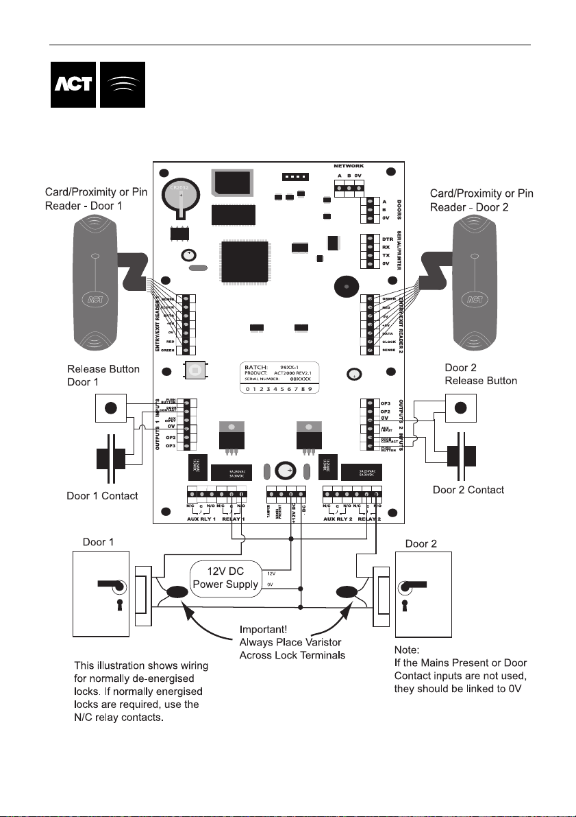
Typical ACT2000 Configuration
(Standalone)
Page 28

ACT1000/2000 Operating Instructions Issue Number 4.10-00
24
03 OFF OFF OFF ON ON
04 OFF OFF ON OFF OFF
05 OFF OFF ON OFF ON
06 OFF OFF ON ON OFF
07 OFF OFF ON ON ON
08 OFF ON OFF OFF OFF
09 OFF ON OFF OFF ON
10 OFF ON OFF ON OFF
11 OFF ON OFF ON ON
12 OFF ON ON OFF OFF
13 OFF ON ON OFF ON
14 OFF ON ON ON OFF
15 OFF ON ON ON ON
16 ON OFF OFF OFF OFF
DS100 Door Station Installation
Page 29

ACT1000/2000 Operating Instructions Issue Number 4.10-00
25
Wiring for Entry/Exit Readers
Page 30

ACT1000/2000 Operating Instructions Issue Number 4.10-00
26
ACT20 PIN Pad Installation Diagram
Page 31

ACT1000/2000 Operating Instructions Issue Number 4.10-00
27
ACT1000/2000 Cable Connections
Page 32
ACT1000/2000 Operating Instructions Issue Number 4.10-00
28
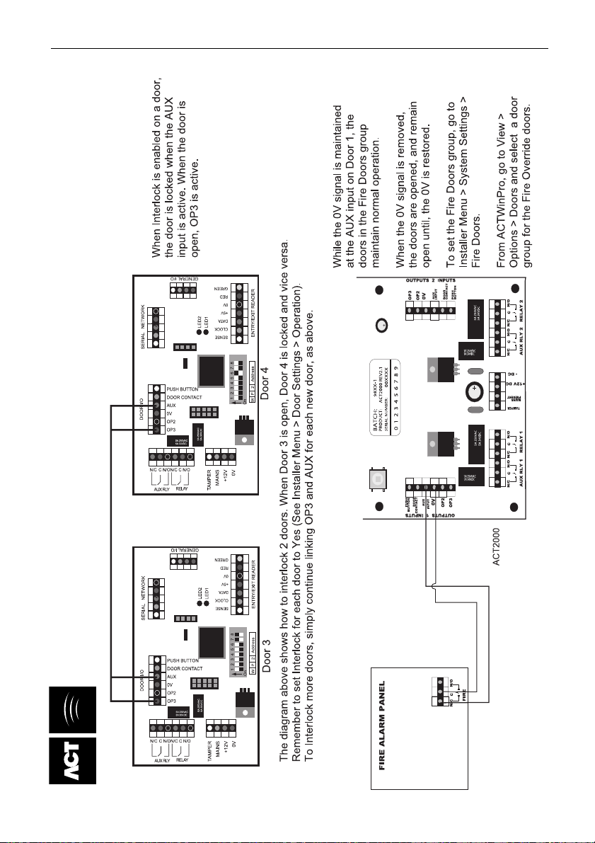
Interlock Configuration
Fire Override Configuration
Page 33
ACT1000/2000 Operating Instructions Issue Number 4.10-00
29
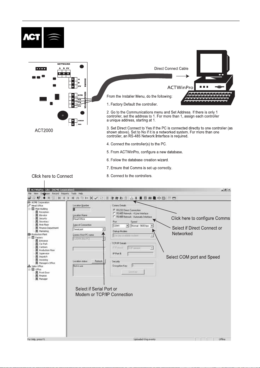
ACT WinPro Configuration
 Loading...