

ACS VPE420 User Manual

Diffusion interne/Internal diffusion
Reference :
Titre/Title
OPE2791
Revision :
B
Text :
INTERACTIVE CONTACTLESS VALIDATOR VPE420 ON-SITE AND
WORKSHOP MAINTENANCE MANUAL
Affaire/Subject :
Classement fichier informatique :
Computer file classification : DTAO
Classement original papier :
Hard copy classification : SERVICE CLIENT PEAGE/TOLL SYSTEM CUSTOMER SERVICE
1
Rel
/Binding1
Destinataires/To
Nbr. of
copies
DTAO Circulation sheet
BERNARD J-L M
BERNE G
CARRON E
M
M
- - -
Observations/Comments
EN
CHIZAT G M
COURTIAL R. M
FROMENT M M
GUETTARD F M
LACOUR M M
LEBIDAN G M
MARROT A M
MOURADKHANIAN A
M
SAINTCIERGE Y M
VALETTE P M
VIAL-TISSOT S M
VILLERET E M
1
Binding: A = Simple Stapling B = Binding C = Hole Perforation M = Distribution by Mail

INTERACTIVE CONTACTLESS VALIDATOR VPE420 ON-SITE AND
WORKSHOP MAINTENANCE MANUAL
- - -
Reference:
This document is property of the association Affiliated Computer Services Solutions France SAS. It can not be reproduced or distributed without prior authorization.
OPE2791
Revision:
B
Text:
EN

Contact Details
Affiliated Computer Services Solutions France SAS
Customer Service:
* Address : Affiliated Computer Services Solutions France SAS,
Rue Claude Chappe - BP 345
07503 GUILHERAND GRANGES CEDEX (FRANCE)
Phone : 33. (0)4.75.81.42.21
Fax : 33. (0)4.75.81.43.38
Return Service (repair):
* Adresse : ASCODI Industries SAS
1 rue Gilles de Roberval
Quartier Briffaut - BP 161
26906 VALENCE Cedex 9 (FRANCE)
Téléphone : 33 (0)4 75 81 42 77
Télécopie : 33 (0)4 75 81 84 41
* Adresse : Affiliated Computer Services Solutions France SAS
Service Clients Public Transport
12, rue Jules Ferry
93110 ROSNY-SOUS-BOIS (FRANCE)
Téléphone : 33.(0)1.56.63.92.00
Télécopie : 33.(0)1.56.63.92.22
This document is property of the association Affiliated Computer Services Solutions France SAS. It can not be reproduced or distributed without prior authorization.
OPE2791 Issue: B Text: EN Page: M1

WARNING
THIS DOCUMENT DESCRIBES ALL THE FUNCTIONS AND OPTIONS THAT CAN BE
IMPLEMENTED ON THIS EQUIPMENT.
IN THIS DOCUMENT, THE FIGURES AND DRAWINGS ARE PROVIDED ONLY AS
EXAMPLE.
IN THIS DOCUMENT, MMI SCREENS OF SOFTWARE TOOLS ARE PROVIDED AS
EXAMPLE.AND CAN BE GIVEN IN EITHER FRENCH OR ENGLISH LANGUAGE.
THE MMI LANGUAGE IS A SETTING PARAMETER.
IN ORDER TO KNOW YOUR EQUIPMENT SETTINGS, REFER TO THE HARDWARE
SPECIFICATIONS OF THE EQUIPMENT.
This document is property of the association Affiliated Computer Services Solutions France SAS. It can not be reproduced or distributed without prior authorization.
Page: M2
OPE2791 Issue: B Text: EN
Modification Sheet
Revision Approval: B
Written by:
Checked or Approved by:
Authorized by :
G. BERNE Customer Service
P. VALETTE Technical Project Leader
A. MARROT
Name Position
Head of Customer
Service
Signature
Revision
Validation/
Application Date
No. of Pages
No. of Attached
Pages
Object and Description of Modification
A November 29, 2010 46 0 First issue.
B February 01, 2011 46 0
Second issue: Modification for FCC and
IC certification
In this document the association of "Affiliated Computer Services Solutions France SAS" is designated by the
following abbreviation: ACS.
This document is property of the association Affiliated Computer Services Solutions France SAS. It can not be reproduced or distributed without prior authorization.
OPE2791 Issue: B Text: EN Page: M3


TABLE OF CONTENTS
Page
CHAPTER 1 : OVERVIEW.................................................................................................. 1
1.
2.
2.1
3.
3.1
3.2
3.2.1 Validator casing...................................................................................................... 5
3.2.2 Support .................................................................................................................. 5
3.2.3 Internal resources .................................................................................................. 5
3.2.4 Touch screen ......................................................................................................... 5
3.2.5 Sound module........................................................................................................ 5
3.2.6 Contactless interface.............................................................................................. 6
3.2.7 Communication interfaces...................................................................................... 6
4.
5.
5.1
ABBREVIATIONS.................................................................................................. 1
PRESENTATION................................................................................................... 2
GENERAL PRESENTATION................................................................................. 2
DESCRIPTION....................................................................................................... 4
BLOCK DIAGRAM ................................................................................................ 4
DESCRIPTION OF FUNCTIONS........................................................................... 5
MODES OF OPERATION...................................................................................... 7
MAIN CHARACTERISTICS................................................................................... 8
PHYSICAL CHARACTERISTICS.......................................................................... 8
5.2
ENVIRONMENTAL CHARACTERISTICS ............................................................. 8
5.2.1 Climatic characteristics........................................................................................... 8
5.2.2 Electrical characteristics......................................................................................... 8
5.3
FUNCTIONAL CHARACTERISTICS..................................................................... 9
6.
6.1
6.2
6.2.1 Details of the connections bo ard.......................................................................... 13
7.
7.1
7.2
7.2.1 Configuration COM1............................................................................................... 19
7.2.2 Configuration COM 2.............................................................................................. 20
8.
9.
EXTERNAL CONNECTIONS................................................................................. 10
VALIDATOR CONNECTION ................................................................................. 11
CONNECTIONS ON CONNECTION BOARD........................................................ 12
CONFIGURATION VPE420................................................................................... 18
VALIDATOR ADDRESS........................................................................................ 18
CONFIGURATIONS AND POLARISATION COM 1 ET COM2.............................. 19
INTERCONNEXIONS ............................................................................................ 21
DOCUMENTATION OF ASSOCIATED EQUIPMENT ........................................... 22
This document is property of the association Affiliated Computer Services Solutions France SAS. It can not be reproduced or distributed without prior
authorization.
OPE2791 Issue: B Text: EN Page: S1

CHAPTER 2 : PREVENTIVE MAINTENANCE................................................................... 23
1.
2.
2.1
2.2
2.3
3.
3.1
3.2
3.3
CHAPTER 3 : CORRECTIVE MAINTENANCE .................................................................. 27
1.
1.1
1.2
CHANGING “OPERATIONAL” CONSUMABLES................................................ 23
ON-SITE PREVENTIVE MAINTENANCE ............................................................. 24
PURPOSE OF THE ON SITE PREVENTIVE MAINTENANCE ............................. 24
NECESSARY TOOLS........................................................................................... 24
ON SITE PREVENTIVE MAINTENANCE OPERATIONS..................................... 24
PREVENTIVE MAINTENANCE IN WORKSHOP.................................................. 25
PURPOSE OF THE WORKSHOP PREVENTIVE MAINTENANCE ...................... 25
NECESSARY TOOLS........................................................................................... 25
ON SITE PREVENTIVE MAINTENANCE OPERATIONS..................................... 25
ON-SITE CORRECTIVE MAINTENANCE............................................................. 27
PURPOSE OF SITE MAINTENANCE................................................................... 27
NECESSARY TOOLS........................................................................................... 27
1.3
SITE CHECKLIST AND REPAIR ACTIONS FOR FAILURE AND ALARM CODES 27
1.3.1 Component code (atlas system)............................................................................ 27
1.3.2 Alarm Code: XXX (atlas system) ........................................................................... 27
1.3.3 List of alarms......................................................................................................... 27
1.4
TABLE OF FAULT CODES.................................................................................. 28
1.4.1 Power up of the VPE 420 ...................................................................................... 29
1.4.2 Application launch ................................................................................................. 29
1.4.3 Application load Procedure in cases where the VPE 420 is on boot...................... 29
1.4.4 Maintenance menu integral to application software............................................... 29
1.5
INITIALIZING VPE 420 ......................................................................................... 30
1.6
TESTS................................................................................................................... 30
1.6.1 Processing of a transport medium......................................................................... 30
1.6.2 Functional tests..................................................................................................... 30
1.7
VPE 420 EXCHANGE........................................................................................... 31
1.8
SUBASSEMBLIES EXCHANGE........................................................................... 32
1.8.1 SAM EXCHANGE.................................................................................................. 32
2.
2.1
CORRECTIVE MAINTENANCE IN THE WORKSHOP......................................... 33
PURPOSE OF CORRECTIVE MAINTENANCE IN THE WORKSHOP................. 33
2.2
NECESSARY TOOLS........................................................................................... 33
2.3
ADJUSTMENTS.................................................................................................... 33
2.4
TEST ..................................................................................................................... 34
This document is property of the association Affiliated Computer Services Solutions France SAS. It can not be reproduced or distributed without prior
authorization.
Page: S2
OPE2791 Issue: B Text: EN

2.5
SUBASSEMBLIES EXCHANGE ........................................................................... 34
2.5.1 Particular point due to the replacement.................................................................. 34
2.5.2 Dismantling/mounting – VPE 420........................................................................... 35
2.5.3 Dismantling/mounting – VPE 420 Front hood assembly......................................... 36
2.5.4 Dismantling/mounting – VPE 420 rear hood assembly........................................... 37
2.5.5 Dismantling/mounting – VPE 420 Frame assembly................................................ 38
2.5.6 Dismantling/mounting – VPE 420 kit touch screen resistive ................................... 39
2.5.7 Dismantling/mounting – VPE 420 kit touch screen capacitive................................. 40
ANNEX 1:
1.
2.
3.
3.1
3.2
3.3
3.4
ANNEX 2:
1.
2.
3.
3.1
3.2
COMPOSITION...................................................................................................... 41
MODE OF USE...................................................................................................... 41
DESCRIPTION OF HEADINGS/LINE ITEMS........................................................ 41
FRAME 1............................................................................................................... 41
FRAME 2............................................................................................................... 41
FRAME 3............................................................................................................... 41
FRAME 4............................................................................................................... 41
PRESENTATION................................................................................................... 43
CERTIFICATION ................................................................................................... 43
EXTERNAL CONNECTION................................................................................... 43
POWER SUPPLY.................................................................................................. 43
SIGNALS............................................................................................................... 43
......
INTERVENTION AND TROUBLESHOOTING FILE ..................................... 41
......
APPENDIX – "PRECAUTIONS AND SAFETY"........................................... 43
4.
4.1
4.2
4.3
4.3.1 Special Cases........................................................................................................ 44
4.4
4.5
5.
6.
7.
8.
This document is property of the association Affiliated Computer Services Solutions France SAS. It can not be reproduced or distributed without prior
authorization.
PRECAUTIONS..................................................................................................... 44
DISCONNECTING THE EQUIPMENT................................................................... 44
VENTILATION....................................................................................................... 44
ELECTRONIC CARD............................................................................................. 44
PACKAGING......................................................................................................... 44
CONTACTLESS FUNCTION FOR INDUSTRY CANADA AND FCC..................... 44
SAFETY................................................................................................................. 45
STANDARDS......................................................................................................... 46
REPAIRS............................................................................................................... 46
CONCLUSION....................................................................................................... 46
OPE2791 Issue: B Text: EN Page: S3

LIST OF FIGURES
Page
Figure 1: Interactive contactless validator + flange assembly....................................... 2
Figure 2: VPE 420 block diagram..................................................................................... 4
Figure 3: Presentation of the external connection.......................................................... 10
Figure 4: Connection board.............................................................................................. 12
Figure 5: Interactive Contactless validator VPE 420 interconnexions .......................... 21
Figure 6: VPE 420 exchange............................................................................................. 31
Figure 7: SAM exchange................................................................................................... 32
Figure 8: Dismantling/mounting – VPE 420..................................................................... 35
Figure 9: Dismantling/mounting – VPE 420 Front hood assembly................................ 36
Figure 10: Dismantling/mounting – VPE 420 rear hood assembly ................................ 37
Figure 11: Dismantling/mounting – VPE 420 Frame assembly...................................... 38
Figure 12: Dismantling/mounting – VPE 420 kit touch screen resistive ....................... 39
Figure 13: Dismantling/mounting – VPE 420 kit touch screen capacitive..................... 40
This document is property of the association Affiliated Computer Services Solutions France SAS. It can not be reproduced or distributed without prior
authorization.
Page: S4
OPE2791 Issue: B Text: EN

CHAPTER 1: OVERVIEW
1. ABBREVIATIONS
VPE 420 Interactive contactless validator type VPE420
CPU Central Processing Unit
FLASH Electrically Programmable Memory (parallel access)
LCD Liquid Cristal Display
LED Light Emitting Diode
MMI Man machine Interface
N.U. Not Used
RS232
Chapter 1: Overview
RS422 Standard data links
RS485
Ethernet
TLB Teleticketing (ContactLess Ticketing)
Ce document est la propriété de la société Affiliated Computer Services Solutions France SAS. Il ne peut être reproduit ou communiqué sans son autorisation
OPE2791 Issue: B Texte : EN Page : 1
Chapter 1: Overview
2. PRESENTATION
2.1 GENERAL PRESENTATION
This device is a contactless reader-encoder unit which processes ISO/IEC 14 443-compliant
contactless cards.
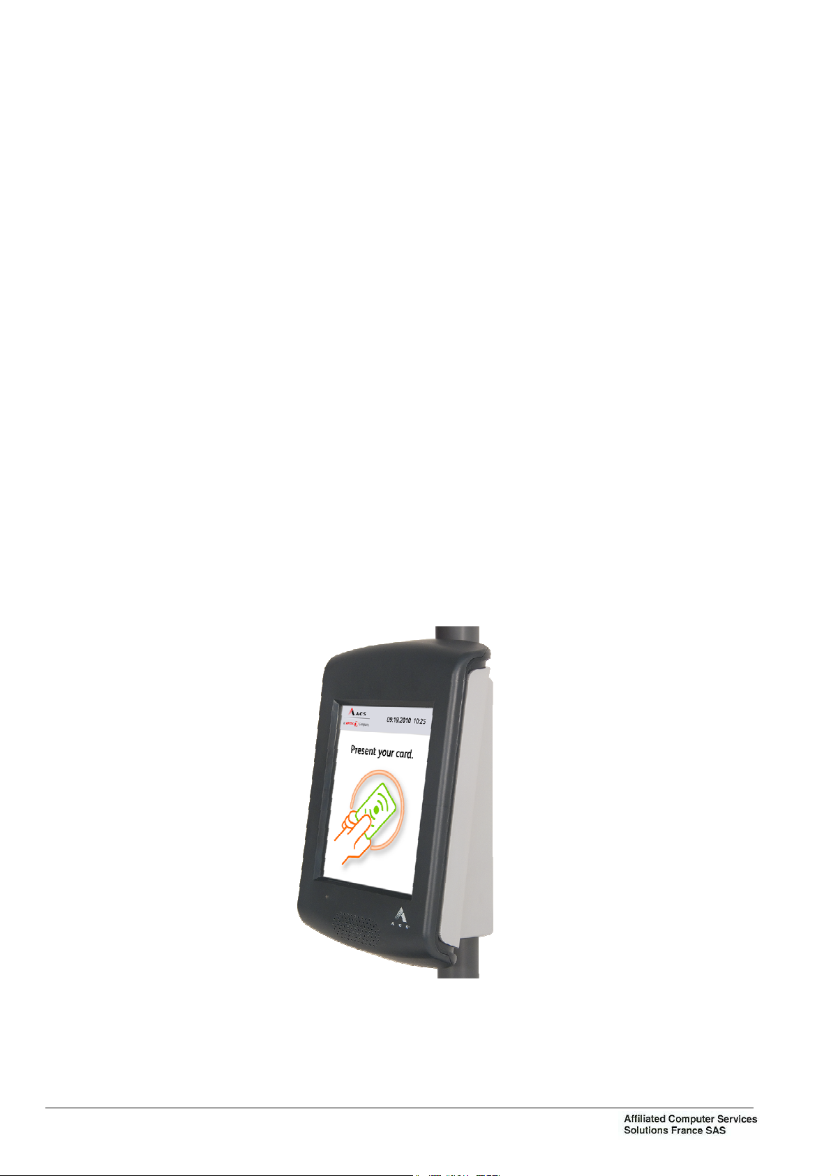
With its modern design similar to mobile communication devices, this interactive validator
VPE420 is much more than a simple validation tool.
With a large color touch screen and voice synthesis, it is a truly modern communication tool,
prestigious for the image of transport networks.
The screen offers a contextual display which indicates only the right information at the right
time (contactless target, keys, pictograms…). This helps user understanding and the flow of
validations is therefore increased.
Of an innovative concept, the wide-range contactless antenna integrated in the screen enables
the easy validation of all types of contactless media: card, ticket, NFC telephone, NFC Smart
Object, simply by placing the media in front of the screen when invited to do so.
Activated on request, the voice synthesis effectively guides users with sight impairments.
Over and beyond ticketing, the combination of sound, image and touch enables a multitude of
possibilities such as the display and vocal announcement of the next stop, transmission of
passenger information messages; performing "on the spot" satisfaction surveys, transmission
of video spots or advertising banners …
However with all this, the validator still remains reliable, robust and ecological. In fact it
contains no battery, which reduces its impact on the environment and eliminates preventive
maintenance operations.
Figure 1: Interactive contactless validator + flange assembly
Ce document est la propriété de la société Affiliated Computer Services Solutions France SAS. Il ne peut être reproduit ou communiqué sans son autorisation
Page : 2
OPE2791 Issue: B Texte : EN
Chapter 1: Overview
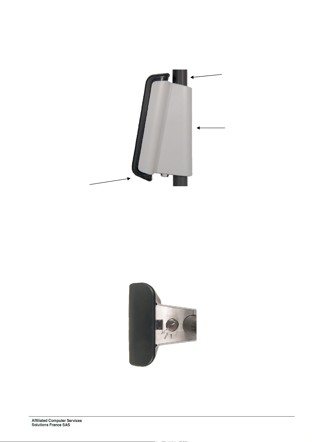
The validator can be fixed on a vertical tube of 25 to 35 mm diameter through a support which
integrates and hides the connectors and cables.
Tube
Support
Validator
Once installed on its support the validator is slightly inclined to facilitate reading and entry on
the screen.
The support integrates an identification memory module which enables the memorization of
information such as the identification of the validator, of the vehicle, its IP address... Thus, in
case of replacement of the validator, the new one automatically recovers the context
information.
The unit is locked by a hidden lock underneath the support.
Unlocking opens a flap with gives access to a USB connector thus enabling the connection of
a USB peripheral (key, keyboard, mouse).
Ce document est la propriété de la société Affiliated Computer Services Solutions France SAS. Il ne peut être reproduit ou communiqué sans son autorisation
OPE2791 Issue: B Texte : EN Page : 3
Chapter 1: Overview
3. DESCRIPTION
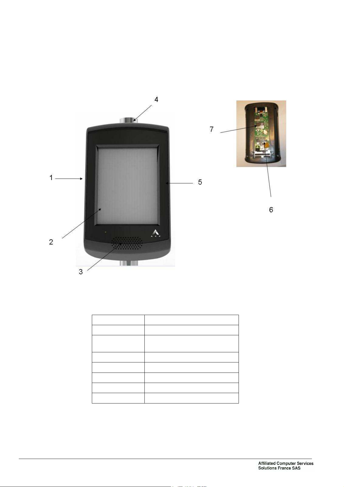
3.1 BLOCK DIAGRAM
Item Designation
1 Validator VPE 420
2 VPE 420 Touch screen
(capacitive or resistive)
3 Speaker
4 RFID Antenna
5 Capacitive touch
6 External connector
7 Brackets SAM
Figure 2: VPE 420 block diagram
Ce document est la propriété de la société Affiliated Computer Services Solutions France SAS. Il ne peut être reproduit ou communiqué sans son autorisation
Page : 4
OPE2791 Issue: B Texte : EN

3.2 DESCRIPTION OF FUNCTIONS
For details, refer to the interactive contactless validator VPE 420 hardware
specifications.
3.2.1 Validator casing
This comprises a front and rear cover in molded ABS/PC with no screw apparent when the
validator is mounted on its support.
3.2.2 Support
It consists of an aluminium flange attached to the tube by 2 threaded rods bent into a U and a
flange cover moulded in ABS-PC attached to the flange to decorate the back of validator.
The flange has an anti-rotation peg to prevent the validator to turn around the tube.
As an option, the validator may be supplied with a support enabling its mounting on a flat
surface (wall, panel…).
Chapter 1: Overview
3.2.3 Internal resources
− ARM core processor.
− Memories:
SDRAM: 128 Mbytes
FLASH: 256 Mbytes extensible to 32 Gbytes
− Identification module (present in the support): 256 bytes.
− Calendar, protected at least 3 days in the event of power supply cutout.
− Operating system: Windows CE 6.0 R3.
3.2.4 Touch screen
6"5 TFT screen mounted in portrait mode.
− Technology: color TFT graphic.
− Definition: 640 x 480 pixels (VGA).
− Touch panel: Projected capacitive, or resistive.
3.2.5 Sound module
The sound module is formed by a loudspeaker by which pre-recorded messages or sounds are
broadcast in Wav or MP3 format (optional) with a sound rating of up to 72 dB at 1 m.
Ce document est la propriété de la société Affiliated Computer Services Solutions France SAS. Il ne peut être reproduit ou communiqué sans son autorisation
OPE2791 Issue: B Texte : EN Page : 5

Chapter 1: Overview
3.2.6 Contactless interface
The contactless interface comprises:
− A radio coupler complying with standard ISO/IEC 14443 (type A and B) supporting the
Innovatron B’ protocol. Optionally, the coupler can integrate the Felica standard (Type C)
and be "EMV contactless" compatible.
− An antenna.
− Four SAM supports.
Main characteristics of interface:
− Carrier frequency: 13.56 MHz.
− Communication speed with contactless card: up to 424 Kbit/s.
− Range: 0 to 10 cm depending on type of contactless media.
3.2.7 Communication interfaces
3.2.7.1 RS232/RS422/RS485/SAEJ1708
Two ports, configurable for RS232 or RS422 or RS485, with one configurable additionally for
SAEJ1708.
3.2.7.2 Ethernet
One Ethernet, 10/100 base TX.
3.2.7.3 USB
One USB 2.0 master interface; accessible under the validator after unlocking.
3.2.7.4 Input - Output interfaces
Two opto-isolated inputs and four dry contact outputs.
Ce document est la propriété de la société Affiliated Computer Services Solutions France SAS. Il ne peut être reproduit ou communiqué sans son autorisation
Page : 6
OPE2791 Issue: B Texte : EN

4. MODES OF OPERATION
According to the address to which the validator is wired, it can work in “master” or “slave”
mode of peripheral equipment.
“Master” Mode
In this mode, the validator is master of the dialogue between equipment (console, beacons,
validator, etc.).
Data exchange and loading of the RTP file may be carried out:
− through an infrared connection from a portable terminal,
− or through a beacon or WiFi system to a land site.
Generally, this mode is used when the validator is alone.
"Slave" Mode
In this case, the validator is linked in long distance transmission through a serial connection to
the master equipment (console or validator).
Generally, this mode is used as slave of a master validator or when the console has a printer.
Chapter 1: Overview
“Autonomous” Mode
Thanks to the internal ticket machine and a back up memory, the validator may function in
“autonomous” mode, i.e. not connected to master equipment.
“Degraded” Mode
Due to a dialogue failure, the validator may function in “degraded” mode until the system works
correctly again. This functioning mode is defined by application parameters. During this mode,
the validations are memorized and will be transmitted to the master machine when the
dialogue is resumed.
Refer to the interactive contactless validator VPE 420 hardware specifications,
functional specifications.
Ce document est la propriété de la société Affiliated Computer Services Solutions France SAS. Il ne peut être reproduit ou communiqué sans son autorisation
OPE2791 Issue: B Texte : EN Page : 7
Chapter 1: Overview
5. MAIN CHARACTERISTICS
5.1 PHYSICAL CHARACTERISTICS
− Height: approximately 250 mm
− Width: approximately 146 mm
− Depth: approx. 95 mm (in relation to the front of the tube)
− Weight of the Validator with the flange support: < 1,5 Kg approximately
These values are given for the Validator + flange assembly.
5.2 ENVIRONMENTAL CHARACTERISTICS
5.2.1 Climatic characteristics
− Operating temperature range: -25°C to +55°C
− Storage temperature range: -30°C to +70°C
− Humidity: 95% HR
− Without condensation at 35°C
− Protection index: IP54.
− Protection impact index IK07.
5.2.2 Electrical characteristics
The Validator is powered on vehicles equipped with a nominal 12-Volt or 24-Volt battery.
− For 24 Vdc Battery 18 Vdc to 32 Vdc.
Maximum power
consumption
− For 12 Vdc Battery 9 Vdc to 16 Vdc.
Maximum power
consumption
24Vdc nominal
600mA
12Vdc nominal
1200mA
The Validator is protected against polarity reversals and against power surges.
The Validator’s power line must be protected by a circuit breaker or fuse, calibrated as follows:
− 2 amperes for one Validator – VPE420.
− 4 optional digital outputs (isolated relay):
2 SPST-NO relays isolated outputs
2 SPDT relays isolated outputs
Contacts ratings:
Max switching voltage: 60VDC
Max switching current: 1A
Contacts protections against overvoltage and over current due to switching operations.
Ce document est la propriété de la société Affiliated Computer Services Solutions France SAS. Il ne peut être reproduit ou communiqué sans son autorisation
Page : 8
OPE2791 Issue: B Texte : EN
 Loading...